EP1837944A2 - Electric power supply control apparatus - Google Patents
Electric power supply control apparatus Download PDFInfo
- Publication number
- EP1837944A2 EP1837944A2 EP07000120A EP07000120A EP1837944A2 EP 1837944 A2 EP1837944 A2 EP 1837944A2 EP 07000120 A EP07000120 A EP 07000120A EP 07000120 A EP07000120 A EP 07000120A EP 1837944 A2 EP1837944 A2 EP 1837944A2
- Authority
- EP
- European Patent Office
- Prior art keywords
- plural
- storage means
- electric power
- outputs
- switching
- Prior art date
- Legal status (The legal status is an assumption and is not a legal conclusion. Google has not performed a legal analysis and makes no representation as to the accuracy of the status listed.)
- Granted
Links
Images




Classifications
-
- H—ELECTRICITY
- H01—ELECTRIC ELEMENTS
- H01M—PROCESSES OR MEANS, e.g. BATTERIES, FOR THE DIRECT CONVERSION OF CHEMICAL ENERGY INTO ELECTRICAL ENERGY
- H01M10/00—Secondary cells; Manufacture thereof
- H01M10/42—Methods or arrangements for servicing or maintenance of secondary cells or secondary half-cells
- H01M10/46—Accumulators structurally combined with charging apparatus
-
- G—PHYSICS
- G01—MEASURING; TESTING
- G01R—MEASURING ELECTRIC VARIABLES; MEASURING MAGNETIC VARIABLES
- G01R31/00—Arrangements for testing electric properties; Arrangements for locating electric faults; Arrangements for electrical testing characterised by what is being tested not provided for elsewhere
- G01R31/36—Arrangements for testing, measuring or monitoring the electrical condition of accumulators or electric batteries, e.g. capacity or state of charge [SoC]
- G01R31/382—Arrangements for monitoring battery or accumulator variables, e.g. SoC
- G01R31/3842—Arrangements for monitoring battery or accumulator variables, e.g. SoC combining voltage and current measurements
-
- G—PHYSICS
- G01—MEASURING; TESTING
- G01R—MEASURING ELECTRIC VARIABLES; MEASURING MAGNETIC VARIABLES
- G01R31/00—Arrangements for testing electric properties; Arrangements for locating electric faults; Arrangements for electrical testing characterised by what is being tested not provided for elsewhere
- G01R31/36—Arrangements for testing, measuring or monitoring the electrical condition of accumulators or electric batteries, e.g. capacity or state of charge [SoC]
- G01R31/392—Determining battery ageing or deterioration, e.g. state of health
-
- H—ELECTRICITY
- H01—ELECTRIC ELEMENTS
- H01M—PROCESSES OR MEANS, e.g. BATTERIES, FOR THE DIRECT CONVERSION OF CHEMICAL ENERGY INTO ELECTRICAL ENERGY
- H01M10/00—Secondary cells; Manufacture thereof
- H01M10/42—Methods or arrangements for servicing or maintenance of secondary cells or secondary half-cells
- H01M10/44—Methods for charging or discharging
- H01M10/441—Methods for charging or discharging for several batteries or cells simultaneously or sequentially
-
- H—ELECTRICITY
- H01—ELECTRIC ELEMENTS
- H01M—PROCESSES OR MEANS, e.g. BATTERIES, FOR THE DIRECT CONVERSION OF CHEMICAL ENERGY INTO ELECTRICAL ENERGY
- H01M10/00—Secondary cells; Manufacture thereof
- H01M10/42—Methods or arrangements for servicing or maintenance of secondary cells or secondary half-cells
- H01M10/48—Accumulators combined with arrangements for measuring, testing or indicating the condition of cells, e.g. the level or density of the electrolyte
- H01M10/482—Accumulators combined with arrangements for measuring, testing or indicating the condition of cells, e.g. the level or density of the electrolyte for several batteries or cells simultaneously or sequentially
-
- H—ELECTRICITY
- H02—GENERATION; CONVERSION OR DISTRIBUTION OF ELECTRIC POWER
- H02J—ELECTRIC POWER NETWORKS; CIRCUIT ARRANGEMENTS OR SYSTEMS FOR SUPPLYING OR DISTRIBUTING ELECTRIC POWER; SYSTEMS FOR STORING ELECTRIC ENERGY
- H02J7/00—Circuit arrangements for charging or discharging batteries or for supplying loads from batteries
- H02J7/50—Circuit arrangements for charging or discharging batteries or for supplying loads from batteries acting upon multiple batteries simultaneously or sequentially
-
- H—ELECTRICITY
- H02—GENERATION; CONVERSION OR DISTRIBUTION OF ELECTRIC POWER
- H02J—ELECTRIC POWER NETWORKS; CIRCUIT ARRANGEMENTS OR SYSTEMS FOR SUPPLYING OR DISTRIBUTING ELECTRIC POWER; SYSTEMS FOR STORING ELECTRIC ENERGY
- H02J7/00—Circuit arrangements for charging or discharging batteries or for supplying loads from batteries
- H02J7/50—Circuit arrangements for charging or discharging batteries or for supplying loads from batteries acting upon multiple batteries simultaneously or sequentially
- H02J7/52—Circuit arrangements for charging or discharging batteries or for supplying loads from batteries acting upon multiple batteries simultaneously or sequentially for charge balancing, e.g. equalisation of charge between batteries
- H02J7/54—Passive balancing, e.g. using resistors or parallel MOSFETs
-
- H—ELECTRICITY
- H02—GENERATION; CONVERSION OR DISTRIBUTION OF ELECTRIC POWER
- H02J—ELECTRIC POWER NETWORKS; CIRCUIT ARRANGEMENTS OR SYSTEMS FOR SUPPLYING OR DISTRIBUTING ELECTRIC POWER; SYSTEMS FOR STORING ELECTRIC ENERGY
- H02J7/00—Circuit arrangements for charging or discharging batteries or for supplying loads from batteries
- H02J7/60—Circuit arrangements for charging or discharging batteries or for supplying loads from batteries including safety or protection arrangements
- H02J7/663—Circuit arrangements for charging or discharging batteries or for supplying loads from batteries including safety or protection arrangements using battery or load disconnect circuits
-
- H—ELECTRICITY
- H02—GENERATION; CONVERSION OR DISTRIBUTION OF ELECTRIC POWER
- H02J—ELECTRIC POWER NETWORKS; CIRCUIT ARRANGEMENTS OR SYSTEMS FOR SUPPLYING OR DISTRIBUTING ELECTRIC POWER; SYSTEMS FOR STORING ELECTRIC ENERGY
- H02J7/00—Circuit arrangements for charging or discharging batteries or for supplying loads from batteries
- H02J7/80—Circuit arrangements for charging or discharging batteries or for supplying loads from batteries including monitoring or indicating arrangements
- H02J7/84—Control of state of health [SOH]
-
- H—ELECTRICITY
- H02—GENERATION; CONVERSION OR DISTRIBUTION OF ELECTRIC POWER
- H02J—ELECTRIC POWER NETWORKS; CIRCUIT ARRANGEMENTS OR SYSTEMS FOR SUPPLYING OR DISTRIBUTING ELECTRIC POWER; SYSTEMS FOR STORING ELECTRIC ENERGY
- H02J7/00—Circuit arrangements for charging or discharging batteries or for supplying loads from batteries
- H02J7/875—Charging or discharging for charge maintenance, battery initiation or rejuvenation
-
- H—ELECTRICITY
- H02—GENERATION; CONVERSION OR DISTRIBUTION OF ELECTRIC POWER
- H02J—ELECTRIC POWER NETWORKS; CIRCUIT ARRANGEMENTS OR SYSTEMS FOR SUPPLYING OR DISTRIBUTING ELECTRIC POWER; SYSTEMS FOR STORING ELECTRIC ENERGY
- H02J7/00—Circuit arrangements for charging or discharging batteries or for supplying loads from batteries
- H02J7/90—Regulation of charging or discharging current or voltage
- H02J7/933—Regulation of charging or discharging current or voltage the cycle being controlled or terminated in response to electric parameters
-
- G—PHYSICS
- G01—MEASURING; TESTING
- G01R—MEASURING ELECTRIC VARIABLES; MEASURING MAGNETIC VARIABLES
- G01R31/00—Arrangements for testing electric properties; Arrangements for locating electric faults; Arrangements for electrical testing characterised by what is being tested not provided for elsewhere
- G01R31/36—Arrangements for testing, measuring or monitoring the electrical condition of accumulators or electric batteries, e.g. capacity or state of charge [SoC]
- G01R31/396—Acquisition or processing of data for testing or for monitoring individual cells or groups of cells within a battery
-
- H—ELECTRICITY
- H01—ELECTRIC ELEMENTS
- H01M—PROCESSES OR MEANS, e.g. BATTERIES, FOR THE DIRECT CONVERSION OF CHEMICAL ENERGY INTO ELECTRICAL ENERGY
- H01M10/00—Secondary cells; Manufacture thereof
- H01M10/05—Accumulators with non-aqueous electrolyte
- H01M10/052—Li-accumulators
-
- H—ELECTRICITY
- H01—ELECTRIC ELEMENTS
- H01M—PROCESSES OR MEANS, e.g. BATTERIES, FOR THE DIRECT CONVERSION OF CHEMICAL ENERGY INTO ELECTRICAL ENERGY
- H01M10/00—Secondary cells; Manufacture thereof
- H01M10/24—Alkaline accumulators
- H01M10/30—Nickel accumulators
-
- H—ELECTRICITY
- H01—ELECTRIC ELEMENTS
- H01M—PROCESSES OR MEANS, e.g. BATTERIES, FOR THE DIRECT CONVERSION OF CHEMICAL ENERGY INTO ELECTRICAL ENERGY
- H01M10/00—Secondary cells; Manufacture thereof
- H01M10/34—Gastight accumulators
- H01M10/345—Gastight metal hydride accumulators
-
- H—ELECTRICITY
- H02—GENERATION; CONVERSION OR DISTRIBUTION OF ELECTRIC POWER
- H02J—ELECTRIC POWER NETWORKS; CIRCUIT ARRANGEMENTS OR SYSTEMS FOR SUPPLYING OR DISTRIBUTING ELECTRIC POWER; SYSTEMS FOR STORING ELECTRIC ENERGY
- H02J7/00—Circuit arrangements for charging or discharging batteries or for supplying loads from batteries
- H02J7/50—Circuit arrangements for charging or discharging batteries or for supplying loads from batteries acting upon multiple batteries simultaneously or sequentially
- H02J7/52—Circuit arrangements for charging or discharging batteries or for supplying loads from batteries acting upon multiple batteries simultaneously or sequentially for charge balancing, e.g. equalisation of charge between batteries
- H02J7/56—Active balancing, e.g. using capacitor-based, inductor-based or DC-DC converters
-
- Y—GENERAL TAGGING OF NEW TECHNOLOGICAL DEVELOPMENTS; GENERAL TAGGING OF CROSS-SECTIONAL TECHNOLOGIES SPANNING OVER SEVERAL SECTIONS OF THE IPC; TECHNICAL SUBJECTS COVERED BY FORMER USPC CROSS-REFERENCE ART COLLECTIONS [XRACs] AND DIGESTS
- Y02—TECHNOLOGIES OR APPLICATIONS FOR MITIGATION OR ADAPTATION AGAINST CLIMATE CHANGE
- Y02E—REDUCTION OF GREENHOUSE GAS [GHG] EMISSIONS, RELATED TO ENERGY GENERATION, TRANSMISSION OR DISTRIBUTION
- Y02E60/00—Enabling technologies; Technologies with a potential or indirect contribution to GHG emissions mitigation
- Y02E60/10—Energy storage using batteries
-
- Y—GENERAL TAGGING OF NEW TECHNOLOGICAL DEVELOPMENTS; GENERAL TAGGING OF CROSS-SECTIONAL TECHNOLOGIES SPANNING OVER SEVERAL SECTIONS OF THE IPC; TECHNICAL SUBJECTS COVERED BY FORMER USPC CROSS-REFERENCE ART COLLECTIONS [XRACs] AND DIGESTS
- Y02—TECHNOLOGIES OR APPLICATIONS FOR MITIGATION OR ADAPTATION AGAINST CLIMATE CHANGE
- Y02T—CLIMATE CHANGE MITIGATION TECHNOLOGIES RELATED TO TRANSPORTATION
- Y02T10/00—Road transport of goods or passengers
- Y02T10/60—Other road transportation technologies with climate change mitigation effect
- Y02T10/70—Energy storage systems for electromobility, e.g. batteries
Definitions
- the present invention relates to an electric power supply control apparatus which controls charge and discharge to and from an electric power supply comprising electrical storage means such as a lead acid cell, nickel-metal hydride cell or lithium ion cell.
- secondary cells such as lead acid cells, nickel-metal hydride cells and lithium ion cells are mounted in electric cars and hybrid cars. Since nickel-metal hydride cells and lithium ion cells show higher energy density than lead acid cells, multi-serial/parallel arrangements of nickel-metal hydride or lithium ion cells are mainly used to drive vehicles. Especially in a large scale cell system needing high current, a plurality of cells are connected in a multi-parallel arrangement.
- the secondary cell changes its state of charge (SOC) and state of health (state of health) as it is charged and discharged repeatedly.
- SOC state of charge
- state of health state of health
- Deterioration differs among the cells. If a certain cell deteriorates faster than the others in the prior art system, the deteriorated cell is completely disconnected from the parallel configuration. Therefore, the time when the system becomes impossible to supply a required amount of current will come earlier. This means the life as a cell system is shorter.
- An electric power supply control apparatus is connected in parallel to plural electric storage means and comprises: plural current measurement means which respectively measure the currents of the plural storage means connected in parallel; plural voltage measurement means which respectively measure the voltages of the plural storage means connected in parallel; plural switching means which respectively disconnect and connect the plural electric storage means from and to the parallel connection; state detection means which receives the outputs of the current measurement means and the outputs of the voltage measurement means and outputs the respective states of the plural electric storage means; and charging and discharging means which receives the outputs of the state detection means and charges and discharges the plural electric storage means.
- the charging and discharging means judges the deterioration states of the plural electric power storage means from the outputs of the state detection means and, based on the judged respective deterioration states of the plural electric storage means, controls switching of the plural switching means.
- the present invention it is possible to lengthen the total life and improve the maintainability of a multi-parallel secondary cell system by suppressing differences in the progress of deterioration among the secondary cells constituting the secondary cell system.
- Fig. 1 shows the configuration of an electric power supply control apparatus according to the present embodiment.
- the following describes the operation of the prior art electric power supply control apparatus for which the present invention was made as mentioned above.
- this electric power supply control apparatus detects a deteriorated cell, it disconnects the cell from the parallel arrangement.
- the prior art electric power supply control apparatus of Fig. 7 has many secondary cells (hereinafter denoted simply as cells) connected in parallel via switches provided for the respective cells. Each switch can disconnect the corresponding cell.
- description is given on the assumption that three cells, namely cell A, Cell B and cell C are connected in parallel.
- this electric power supply control apparatus obtains a required amount of output current by using the three cells or cell A, cell B and cell C.
- cell C is disconnected from the parallel configuration since cell C exceeds the deteriorated cell replacement threshold.
- time t1 to time t2 ((b) in the figure)
- a region occurs where a required amount of output current can not be obtained since only cells A and B are used as shown in Fig. 7.
- Fig. 8 shows the state of health of each cell in the prior art electric power supply control apparatus shown in Fig. 7. Since deterioration differs among the cells, even when cell C exceeds the deteriorated cell replacement threshold, it is possible that cell A and cell B have not yet deteriorated substantially as shown in Fig. 8. It is therefore impossible to replace the deteriorated cell C together with cells A and B at a time, which lowers the maintainability.
- Fig. 1 shows the configuration of the present electric power supply control apparatus embodiment.
- the electric power supply control apparatus of Fig. 1 comprises electrical storage units 10, 20 and 30, current measurement units 40, 41 and 42, voltage measurement unit 50, switching units 60, 61 and 62, state detection unit 70, charging and discharging unit 80 and a load 90.
- the electrical storage units 10, 20 and 30 respectively have internal resistances 11, 21 and 31 and open circuit voltages (electromotive forces) 12, 22 and 32.
- the electrical storage unit 10 is connected in series to the current measurement unit 40 and the switching unit 60.
- the electrical storage unit 20 is connected in series to the current measurement unit 41 and the switching unit 61 while the electrical storage unit 30 is connected in series to the current measurement unit 42 and the switching unit 62.
- These circuits namely the one comprising the electrical storage unit 10, the current measurement unit 40 and the switching unit 60, the one comprising the electrical storage unit 20, the current measurement unit 41 and the switching unit 61 and the one comprising the electrical storage unit 30, the current measurement unit 42 and the switching unit 62 are mutually connected in parallel.
- the circuit comprising the electrical storage unit 10, the current measurement unit 40 and the switching unit 60, the circuit comprising the electrical storage unit 20, the current measurement unit 41 and the switching unit 61 and the circuit comprising the electrical storage unit 30, the current measurement unit 42 and the switching unit 62 are all connected in parallel with the voltage measurement unit 50.
- the circuit comprising the electrical storage unit 10, the current measurement unit 40 and the switching unit 60, the circuit comprising the electrical storage unit 20, the current measurement unit 41 and the switching unit 61 and the circuit comprising the electrical storage unit 30, the current measurement unit 42 and the switching unit 62 are all connected in parallel with the charging and discharging unit 80.
- the charging and discharging unit 80 is also connected to the load 90 which comprises a motor, electric generator, electronic equipment and the like.
- the voltage measured by the voltage measurement unit 50 is entered into the state detection unit 70.
- the currents measured respectively by the current measurement unit 40, 41 and 42 are entered into the state detection unit 70.
- the currents, voltages and resistances calculated by the state detection unit 70 are entered into the charging and discharging unit 80.
- the charging and discharging unit 80 performs calculation from the status values, for example, voltages, currents and resistances supplied from the state detection unit 70, and based on the result of calculation, controls the charging and discharging currents to and from the electric storage units 10, 20 and 30.
- the electric storage units 10, 20 and 30 of the present embodiment are rechargeable electric storage devices such as rechargeable lithium cells, nickel-metal hydride cells, lead acid cells, Ni-Cd cells, electric double layer capacitors or the like.
- Each of the electric storage units 10, 20 and 30 is composed of such an electric storage device or a plurality of such electric storage devices connected in parallel or in series.
- Each of the current measurement units 40, 41 and 42 comprises a current sensor such as a hall CT or shunt resistance type current sensor to measure the current which flows through the electric storage unit 10, 20 or 30.
- the voltage measurement unit 50 comprises voltage dividing resistors, an operational amplifier, A/D converter and other electronic parts to measure the voltage of the electrical storage units 10, 20 and 30.
- Each of the switching units 60, 61 and 62 comprises a relay and power semiconductor device to connect and disconnect the electrical storage unit 10, 20 or 30 to and from the parallel configuration.
- the state detection unit 70 comprises a microcomputer, peripheral IC and others to detect the states (voltages, currents and resistances) of the electrical storage units 10, 20 and 30 from the outputs of the current measurement units 40, 41 and 42 and voltage measurement unit 50.
- the charging and discharging unit 80 comprises a power transformer consisting of a converter, inverter, etc. to control the current, voltage and power which are to be supplied to or output from the electrical storage units 10, 20 and 30.
- the charging and discharging unit 80 judges the states of health of the electrical storage units 10, 20 and 30 from the status signal which is output from the state detection unit 70. Based on these states of health, the charging and discharging unit 80 controls switching of the switching units 60, 61 and 62.
- the currents which respectively flow through the electrical storage units 10, 20 and 30 vary depending on their internal resistances 11, 21 and 31 and open circuit voltages (electromotive forces) 12, 22 and 32 and the input or output current, voltage, power and others of the charging and discharging unit 80.
- the state detection unit 70 detects the status quantities of internal resistances 11, 21 and 31 and of open circuit voltages (electromotive forces) 12, 22 and 32 of the electrical storage units 10, 20 and 30, and reports these status quantities to the charging and discharging unit 80.
- the charging and discharging unit 80 controls its input or output current, voltage and power and turns on and off the switching units 60, 61 and 62.
- Fig. 2 illustrates how the electrical storage units 10, 20 and 30 are controlled by turning on and off the switching units 60, 61 and 62 shown in Fig. 1.
- SOH states of health
- the charging and discharging unit 80 dynamically ranks the degrees of deterioration of the electrical storage units 10, 20 and 30 connected mutually in parallel.
- Discharging is performed as described above.
- the switching units are turned on/off so that the charging priority is given in the increasing order of the state of charge (SOC). This makes the respective cells uniform in the state of charge (SOC).
- the respective cells are dynamically ranked in the degree of deterioration and the least deteriorated cells are selectively used so that all cells deteriorate uniformly. Since this prevents a certain cell from deteriorating faster and consequently lowering the output capacity of the cell system to below the required level, the life of the cell system can be made longer. In addition, since all cells deteriorate uniformly, all of them can be replaced at a time after deteriorated. This raises the maintainability. More preferably, the state of health of each cell is indicated to the external.
- Fig. 3 Provided in Fig. 3 is a process flow of carrying out the control method shown in Fig. 2.
- S1 the respective cells are connected in parallel.
- S2 the respective cells are dynamically ranked in the degree of deterioration.
- S3 the required output current is determined.
- S4 it is judged whether the output current can be supplied by only one cell. If possible, control goes to S5. If not, control goes to S6.
- S5 the most deteriorated cells C and B are disconnected from the parallel configuration.
- S6 it is judged whether the output current can be supplied by two cells. If possible, control goes to S7. If not possible, control goes to S8.
- S7 only the most deteriorated cell C is disconnected from the parallel configuration.
- S8 any cell is not disconnected from the parallel configuration since three cells are required to supply the output current. Then, control goes back to S2 to repeat the process.
- Fig. 4 shows how the cells deteriorate as a result of the control method shown in Fig. 2.
- this control method all cells deteriorate uniformly.
- cell C exceeds the deteriorated cell replacement threshold, cells A and B are about to reach the threshold. Therefore, the deteriorated cell C may be replaced together with cells A and B at a time. This means high maintainability.
- the electrical storage units 10, 20 and 30 are rechargeable electrical storage devices such as rechargeable lithium cells, nickel-metal hydride cells, lead acid cells, Ni-Cd cells, electric double layer capacitors or the like.
- the electrical storage units 10, 20 and 30 may be fuel cells instead of such storage units.
- the charging and discharging unit 80 is replaced by discharging control means which performs discharging control according to the control flow of Fig. 3.
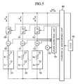
- Fig. 5 shows the configuration of the electrical power supply control apparatus according to the present embodiment.
- the present embodiment is same as the first embodiment of Fig. 1 except that load 90 outputs a status signal to the charging and discharging unit 80.
- This status signal includes information such as the current expected to be required by the load 90 and the current velocity of the vehicle which the load 90 is driving.
- the charging and discharging unit 80 connects/disconnects the electrical storage units 10, 20 and 30 based on this status signal and their degrees of deterioration. Since the current to be required by the load 90 can be recognized, the charging and discharging unit 80 can connect/disconnect the electrical storage units 10, 20 and 30 in advance, which allows smooth supply of the output current.
- Fig. 6 shows the configuration of the electrical power supply control apparatus according to the present embodiment.
- the present embodiment is same as the first embodiment of Fig. 1 except that the circuit comprising a resistor 100 and a switch 110, the circuit comprising a resistor 101 and a switch 111 and the circuit comprising a resistor 102 and a switch 112 are respectively connected in parallel with the switching units 60, 61 and 62.
- These resistors 100, 101 and 102 prevent the switching units 60, 61 and 62 from causing large inrush current when they are turned on.
- the switch 110 is turned on in advance. This makes the electrical storage unit 10 free from large inrush current when the switching unit 60 is turned on.
Landscapes
- Engineering & Computer Science (AREA)
- Power Engineering (AREA)
- General Chemical & Material Sciences (AREA)
- Chemical & Material Sciences (AREA)
- Chemical Kinetics & Catalysis (AREA)
- Electrochemistry (AREA)
- Manufacturing & Machinery (AREA)
- Physics & Mathematics (AREA)
- General Physics & Mathematics (AREA)
- Charge And Discharge Circuits For Batteries Or The Like (AREA)
- Secondary Cells (AREA)
- Electric Propulsion And Braking For Vehicles (AREA)
- Stand-By Power Supply Arrangements (AREA)
Abstract
Description
- The present invention relates to an electric power supply control apparatus which controls charge and discharge to and from an electric power supply comprising electrical storage means such as a lead acid cell, nickel-metal hydride cell or lithium ion cell.
- Generally, secondary cells such as lead acid cells, nickel-metal hydride cells and lithium ion cells are mounted in electric cars and hybrid cars. Since nickel-metal hydride cells and lithium ion cells show higher energy density than lead acid cells, multi-serial/parallel arrangements of nickel-metal hydride or lithium ion cells are mainly used to drive vehicles. Especially in a large scale cell system needing high current, a plurality of cells are connected in a multi-parallel arrangement.
- The secondary cell changes its state of charge (SOC) and state of health (state of health) as it is charged and discharged repeatedly. Usually, if a cell deteriorates, its internal resistance increases and its full charge capacity decreases. Since this lowers the total output of the system, it is necessary to disconnect deteriorated cells from the system or replace them by brand-new ones.
- For example, in a prior art multi-parallel cell system described in
Japanese Patent Laid-open No. 2001-185228 - Deterioration differs among the cells. If a certain cell deteriorates faster than the others in the prior art system, the deteriorated cell is completely disconnected from the parallel configuration. Therefore, the time when the system becomes impossible to supply a required amount of current will come earlier. This means the life as a cell system is shorter.
- In addition, when a deteriorated cell is disconnected from the system and replaced by a brand-new one, the other cells may be not so deteriorated as to need to be replaced since deterioration differs among the cells. This increases the number of times replacement must be done, which lowers the maintainability.
- It is an object of the present invention to lengthen the life of a multi-parallel cell system and improve the maintainability thereof by keeping the constituent cells uniform in deterioration.
- An electric power supply control apparatus according to the present invention is connected in parallel to plural electric storage means and comprises: plural current measurement means which respectively measure the currents of the plural storage means connected in parallel; plural voltage measurement means which respectively measure the voltages of the plural storage means connected in parallel; plural switching means which respectively disconnect and connect the plural electric storage means from and to the parallel connection; state detection means which receives the outputs of the current measurement means and the outputs of the voltage measurement means and outputs the respective states of the plural electric storage means; and charging and discharging means which receives the outputs of the state detection means and charges and discharges the plural electric storage means. The charging and discharging means judges the deterioration states of the plural electric power storage means from the outputs of the state detection means and, based on the judged respective deterioration states of the plural electric storage means, controls switching of the plural switching means.
- According to the present invention, it is possible to lengthen the total life and improve the maintainability of a multi-parallel secondary cell system by suppressing differences in the progress of deterioration among the secondary cells constituting the secondary cell system.
- Other objects and advantages of the invention will become apparent from the following description of embodiments with reference to the accompanying drawings in which:
- Fig. 1 is a diagram to explain the general configuration of an electric power supply control apparatus according to a first embodiment;
- Fig. 2 is a diagram to explain the principles of operation of the electric power supply control apparatus according to the first embodiment;
- Fig. 3 is a diagram to explain the flows of operation of the electric power supply control apparatus according to the first embodiment;
- Fig. 4 is a diagram to explain how electrical storage means deteriorate in the electric power supply control apparatus according to the first embodiment;
- Fig. 5 is a diagram to explain the general configuration of an electric power supply control apparatus according to a second embodiment;
- Fig. 6 is a diagram to explain the general configuration of an electric power supply control apparatus according to a third embodiment;
- Fig. 7 is a diagram to explain the principles of operation of the prior art of the electric power supply control apparatus; and
- Fig. 8 is a diagram to explain how electrical storage means deteriorate in the prior art of the electric power supply control apparatus.
- Embodiments of the present invention will be described below in detail with reference to the drawings. Note that each of the components which are included in more than one embodiments is given the same reference numeral without redundant description.
- Fig. 1 shows the configuration of an electric power supply control apparatus according to the present embodiment. Prior to Fig. 1, the following describes the operation of the prior art electric power supply control apparatus for which the present invention was made as mentioned above. As shown in Fig. 7, if this electric power supply control apparatus detects a deteriorated cell, it disconnects the cell from the parallel arrangement.
- The prior art electric power supply control apparatus of Fig. 7 has many secondary cells (hereinafter denoted simply as cells) connected in parallel via switches provided for the respective cells. Each switch can disconnect the corresponding cell. Here, description is given on the assumption that three cells, namely cell A, Cell B and cell C are connected in parallel. During the period of time t0 to time t1 ((a) in the figure), this electric power supply control apparatus obtains a required amount of output current by using the three cells or cell A, cell B and cell C. Then, at time t1, cell C is disconnected from the parallel configuration since cell C exceeds the deteriorated cell replacement threshold. During the period of time t1 to time t2 ((b) in the figure), a region occurs where a required amount of output current can not be obtained since only cells A and B are used as shown in Fig. 7.
- Usually, since deterioration differs among the cells, the time when a required amount of output current becomes impossible to obtain comes earlier if a cell deteriorates faster than the others as mentioned above. In other words, this shortens the life of the total cell system. In addition, when a deteriorated cell is replaced by a brand-new one, the other cells may be not so deteriorated as to need to be replaced since deterioration differs among the cells. Therefore, it is not possible to replace all cells at a time, which may lower the maintainability.
- Fig. 8 shows the state of health of each cell in the prior art electric power supply control apparatus shown in Fig. 7. Since deterioration differs among the cells, even when cell C exceeds the deteriorated cell replacement threshold, it is possible that cell A and cell B have not yet deteriorated substantially as shown in Fig. 8. It is therefore impossible to replace the deteriorated cell C together with cells A and B at a time, which lowers the maintainability.
- In addition, disconnecting or replacing cell C which deteriorates faster shortens its life as a cell system since the period during which the effective output can be obtained is shortened.
- Fig. 1 shows the configuration of the present electric power supply control apparatus embodiment. The electric power supply control apparatus of Fig. 1 comprises
electrical storage units current measurement units voltage measurement unit 50,switching units state detection unit 70, charging anddischarging unit 80 and aload 90. Theelectrical storage units internal resistances - The electrical storage unit 10 is connected in series to the
current measurement unit 40 and theswitching unit 60. Likewise, theelectrical storage unit 20 is connected in series to thecurrent measurement unit 41 and theswitching unit 61 while theelectrical storage unit 30 is connected in series to thecurrent measurement unit 42 and theswitching unit 62. These circuits, namely the one comprising the electrical storage unit 10, thecurrent measurement unit 40 and theswitching unit 60, the one comprising theelectrical storage unit 20, thecurrent measurement unit 41 and theswitching unit 61 and the one comprising theelectrical storage unit 30, thecurrent measurement unit 42 and theswitching unit 62 are mutually connected in parallel. - In addition, the circuit comprising the electrical storage unit 10, the
current measurement unit 40 and theswitching unit 60, the circuit comprising theelectrical storage unit 20, thecurrent measurement unit 41 and theswitching unit 61 and the circuit comprising theelectrical storage unit 30, thecurrent measurement unit 42 and theswitching unit 62 are all connected in parallel with thevoltage measurement unit 50. As well, the circuit comprising the electrical storage unit 10, thecurrent measurement unit 40 and theswitching unit 60, the circuit comprising theelectrical storage unit 20, thecurrent measurement unit 41 and theswitching unit 61 and the circuit comprising theelectrical storage unit 30, thecurrent measurement unit 42 and theswitching unit 62 are all connected in parallel with the charging anddischarging unit 80. The charging and dischargingunit 80 is also connected to theload 90 which comprises a motor, electric generator, electronic equipment and the like. The voltage measured by thevoltage measurement unit 50 is entered into thestate detection unit 70. As well, the currents measured respectively by thecurrent measurement unit state detection unit 70. The currents, voltages and resistances calculated by thestate detection unit 70 are entered into the charging and dischargingunit 80. To measure the states of theelectrical storage units - The charging and
discharging unit 80 performs calculation from the status values, for example, voltages, currents and resistances supplied from thestate detection unit 70, and based on the result of calculation, controls the charging and discharging currents to and from theelectric storage units electric storage units electric storage units current measurement units electric storage unit voltage measurement unit 50 comprises voltage dividing resistors, an operational amplifier, A/D converter and other electronic parts to measure the voltage of theelectrical storage units units electrical storage unit state detection unit 70 comprises a microcomputer, peripheral IC and others to detect the states (voltages, currents and resistances) of theelectrical storage units current measurement units voltage measurement unit 50. The charging and dischargingunit 80 comprises a power transformer consisting of a converter, inverter, etc. to control the current, voltage and power which are to be supplied to or output from theelectrical storage units unit 80 judges the states of health of theelectrical storage units state detection unit 70. Based on these states of health, the charging and dischargingunit 80 controls switching of the switchingunits - The currents which respectively flow through the
electrical storage units internal resistances unit 80. Thus, thestate detection unit 70 detects the status quantities ofinternal resistances electrical storage units unit 80. According to these status quantities, the charging and dischargingunit 80 controls its input or output current, voltage and power and turns on and off the switchingunits - Fig. 2 illustrates how the
electrical storage units units electrical storage units internal resistances unit 80 dynamically ranks the degrees of deterioration of theelectrical storage units - The following description is made on the assumption that the electrical storage units are three cells connected in parallel. In this example, deterioration of cell C is the largest while that of cell A is the smallest. Deterioration of cell B is intermediary between cell A and cell C.
- During the period ((c) in Fig. 2) of time t0 to t1 in Fig. 2, since the output current can be supplied by one cell, only the least deteriorated cell A is discharged. During the period ((b) in Fig. 2) of time t1 to t2, since two cells are needed to supply the output current, the least deteriorated two cells A and B are discharged. During the period ((a) in Fig. 2) of time t2 to t3, since three cells are needed to supply the output current, all cells A, B and C are discharged. The t3-t4 period is similar to the t1-t2 period. As well, the t4-t5 period is similar to the t0-t1 period.
- Discharging is performed as described above. When charging is performed, the switching units are turned on/off so that the charging priority is given in the increasing order of the state of charge (SOC). This makes the respective cells uniform in the state of charge (SOC).
- As mentioned above, the respective cells are dynamically ranked in the degree of deterioration and the least deteriorated cells are selectively used so that all cells deteriorate uniformly. Since this prevents a certain cell from deteriorating faster and consequently lowering the output capacity of the cell system to below the required level, the life of the cell system can be made longer. In addition, since all cells deteriorate uniformly, all of them can be replaced at a time after deteriorated. This raises the maintainability. More preferably, the state of health of each cell is indicated to the external.
- Provided in Fig. 3 is a process flow of carrying out the control method shown in Fig. 2. At first, in S1, the respective cells are connected in parallel. Then, in S2, the respective cells are dynamically ranked in the degree of deterioration. Then, in S3, the required output current is determined. Then, in S4, it is judged whether the output current can be supplied by only one cell. If possible, control goes to S5. If not, control goes to S6. In S5, the most deteriorated cells C and B are disconnected from the parallel configuration. In S6, it is judged whether the output current can be supplied by two cells. If possible, control goes to S7. If not possible, control goes to S8. In S7, only the most deteriorated cell C is disconnected from the parallel configuration. In S8, any cell is not disconnected from the parallel configuration since three cells are required to supply the output current. Then, control goes back to S2 to repeat the process.
- Fig. 4 shows how the cells deteriorate as a result of the control method shown in Fig. 2. In this control method, all cells deteriorate uniformly. When cell C exceeds the deteriorated cell replacement threshold, cells A and B are about to reach the threshold. Therefore, the deteriorated cell C may be replaced together with cells A and B at a time. This means high maintainability.
- In addition, since all cells deteriorate uniformly, all cells can be used until the deteriorated cell C is disconnected or replaced. This lengthens the period during which the effective output can be obtained, resulting in a longer life as the cell system.
- The present embodiment has been described on the assumption that the
electrical storage units electrical storage units unit 80 is replaced by discharging control means which performs discharging control according to the control flow of Fig. 3. - Fig. 5 shows the configuration of the electrical power supply control apparatus according to the present embodiment. The present embodiment is same as the first embodiment of Fig. 1 except that
load 90 outputs a status signal to the charging and dischargingunit 80. This status signal includes information such as the current expected to be required by theload 90 and the current velocity of the vehicle which theload 90 is driving. The charging and dischargingunit 80 connects/disconnects theelectrical storage units load 90 can be recognized, the charging and dischargingunit 80 can connect/disconnect theelectrical storage units - Fig. 6 shows the configuration of the electrical power supply control apparatus according to the present embodiment. The present embodiment is same as the first embodiment of Fig. 1 except that the circuit comprising a
resistor 100 and aswitch 110, the circuit comprising aresistor 101 and a switch 111 and the circuit comprising aresistor 102 and aswitch 112 are respectively connected in parallel with the switchingunits resistors switching units switching unit 60 to use the electrical storage unit 10, theswitch 110 is turned on in advance. This makes the electrical storage unit 10 free from large inrush current when the switchingunit 60 is turned on. - While the invention has been described in its preferred embodiments, it is to be understood that the words which have been used are words of description rather than limitation and that changes within the purview of the appended claims may be made without departing from the true scope and spirit of the invention in its broader aspects.
Claims (14)
- An electric power supply control apparatus which is connected in parallel to plural electric storage means, comprising:plural current measurement means which respectively measure the currents of the plural storage means connected in parallel;plural voltage measurement means which respectively measure the voltages of the plural storage means connected in parallel;plural switching means which respectively disconnect and connect the plural electric storage means from and to the parallel connection;state detection means which receives the outputs of the current measurement means and the outputs of the voltage measurement means and outputs the respective states of the plural electric storage means; andcharging and discharging means which receives the outputs of the state detection means and charges and discharges the plural electric storage means;wherein the charging and discharging means judges the deterioration states of the plural electric power storage means from the outputs of the state detection means and, based on the judged respective deterioration states of the plural electric storage means, controls switching of the plural switching means.
- The electric power supply control apparatus according to Claim 1, wherein each of the electric storage means comprises a plurality of unit electric storage means connected in series.
- The electric power supply control apparatus according to Claim 1, wherein the electric storage means to be charged or discharged are selected in the order of the least deteriorated one to the most deteriorated one.
- The electric power supply control apparatus according to Claim 1, wherein judgment of the deterioration states of the plural electric power storage means and switching of the switching of the plural switching means are dynamically performed.
- The electric power supply control apparatus according to Claim 1, wherein the electric storage means to be charged are selected in the order of the least charged one to the most charged one.
- The electric power supply control apparatus according to Claim 1, wherein the deterioration states of the plural electric storage means are indicated to the external.
- An electric power supply control apparatus which is connected in parallel to plural electric storage means, comprising:plural current measurement means which respectively measure the currents of the plural storage means connected in parallel;plural voltage measurement means which respectively measure the voltages of the plural storage means connected in parallel;plural switching means which respectively disconnect and connect the plural electric storage means from and to the parallel connection;state detection means which receives the outputs of the current measurement means and the outputs of the voltage measurement means and outputs the respective states of the plural electric storage means; andcharging and discharging means which receives the outputs of the state detection means and charges and discharges the plural electric storage means, wherein:the charging and discharging means also receives a status signal which is output from a load; andthe charging and discharging means judges the deterioration states of the plural electric power storage means from the outputs of the state detection means and, based on the judged respective deterioration states of the plural electric storage means and the status signal output from the load, controls switching of the plural switching means.
- The electric power supply control apparatus according to Claim 7, wherein each of the electric storage means comprises a plurality of unit electric storage means connected in series.
- The electric power supply control apparatus according to Claim 7, wherein the electric storage means to be charged or discharged are selected in the order of the least deteriorated one to the most deteriorated one.
- The electric power supply control apparatus according to Claim 7, wherein judgment of the deterioration states of the plural electric power storage means and switching of the switching of the plural switching means are dynamically performed.
- The electric power supply control apparatus according to Claim 7, wherein the status signal output from the load is indicative of the amount of current required by the load.
- The electric power supply control apparatus according to Claim 7, wherein the electric storage means to be charged are selected in the order of the least charged one to the most charged one.
- The electric power supply control apparatus according to Claim 7, wherein the deterioration states of the plural electric storage means are indicated to the external.
- An electric power supply control apparatus which is connected in parallel to plural electric storage means, comprising:plural current measurement means which respectively measure the currents of the plural storage means connected in parallel;plural voltage measurement means which respectively measure the voltages of the plural storage means connected in parallel;first plural switching means which respectively disconnect and connect the plural electric storage means from and to the parallel connection;state detection means which receives the outputs of the current measurement means and the outputs of the voltage measurement means and outputs the respective states of the plural electric storage means; andcharging and discharging means which receives the outputs of the state detection means and charges and discharges the plural electric storage means, wherein:each of the plural switching means has a component connected in parallel thereto wherein the component comprises second switching means and a resistor connected in series to the second switching means; andthe charging and discharging means judges the deterioration states of the plural electric power storage means from the outputs of the state detection means and, based on the judged respective deterioration states of the plural electric storage means, controls switching of the first and second switching means.
Applications Claiming Priority (1)
| Application Number | Priority Date | Filing Date | Title |
|---|---|---|---|
| JP2006081910A JP4572850B2 (en) | 2006-03-24 | 2006-03-24 | Power control device |
Publications (3)
| Publication Number | Publication Date |
|---|---|
| EP1837944A2 true EP1837944A2 (en) | 2007-09-26 |
| EP1837944A3 EP1837944A3 (en) | 2010-03-10 |
| EP1837944B1 EP1837944B1 (en) | 2014-04-23 |
Family
ID=38198322
Family Applications (1)
| Application Number | Title | Priority Date | Filing Date |
|---|---|---|---|
| EP07000120.1A Not-in-force EP1837944B1 (en) | 2006-03-24 | 2007-01-04 | Electric power supply control apparatus |
Country Status (4)
| Country | Link |
|---|---|
| EP (1) | EP1837944B1 (en) |
| JP (1) | JP4572850B2 (en) |
| CN (1) | CN101043143B (en) |
| TW (1) | TW200737566A (en) |
Cited By (45)
| Publication number | Priority date | Publication date | Assignee | Title |
|---|---|---|---|---|
| GB2462467A (en) * | 2008-08-08 | 2010-02-10 | P G Drives Technology Ltd | Charging a multi-cell power supply |
| GB2465469A (en) * | 2008-11-19 | 2010-05-26 | Hitachi Ltd | Power storage control system |
| WO2010116671A1 (en) * | 2009-03-30 | 2010-10-14 | 株式会社日本総合研究所 | Battery control device, battery control method, and vehicle |
| WO2012049963A1 (en) * | 2010-10-15 | 2012-04-19 | 三洋電機株式会社 | Power system comprising storage batteries |
| WO2012111234A1 (en) * | 2011-02-18 | 2012-08-23 | 三洋電機株式会社 | Power supply system |
| US20120249057A1 (en) * | 2011-03-30 | 2012-10-04 | Sony Corporation | Charge control device, charge control method, program, and system |
| GB2490271A (en) * | 2008-08-08 | 2012-10-24 | P G Drives Technology Ltd | Monitoring level of charge of a multi-cell power supply |
| CN102761154A (en) * | 2011-04-27 | 2012-10-31 | 本田技研工业株式会社 | power supply unit |
| US20130106357A1 (en) * | 2011-10-31 | 2013-05-02 | Cobasys, Llc | Intelligent charging and discharging system for parallel configuration of series cells with semiconductor switching |
| US20130193768A1 (en) * | 2010-10-15 | 2013-08-01 | Sanyo Electric Co.,Ltd. | Power supply system |
| WO2013066867A3 (en) * | 2011-10-31 | 2013-10-17 | Cobasys, Llc | Parallel configuration of series cells with semiconductor switching |
| EP2557428A4 (en) * | 2010-04-09 | 2014-04-16 | Toyota Motor Co Ltd | DEVICE FOR DETERMINING DEGRADATION METHOD FOR DETERMINING DEGRADATION OF SECONDARY BATTERY |
| GB2507955A (en) * | 2012-09-24 | 2014-05-21 | Siemens Elema Ab | Parallel charging & discharging of multiple lead acid batteries |
| CN103975500A (en) * | 2011-12-12 | 2014-08-06 | 日产自动车株式会社 | battery connection control |
| EP2767431A1 (en) * | 2013-02-18 | 2014-08-20 | Schneider Electric Industries SAS | Method for optimising the recharging energy and durability of electric batteries |
| US20140265600A1 (en) * | 2011-11-01 | 2014-09-18 | Nissan Motor Co., Ltd. | Power supply controller |
| EP2424070A3 (en) * | 2010-08-26 | 2015-07-01 | Hitachi Ltd. | Battery control system and vehicle system with battery control system |
| US9106077B2 (en) | 2011-03-29 | 2015-08-11 | Panasonic Intellectual Property Management Co., Ltd. | Power control apparatus and power control method |
| EP2692587A4 (en) * | 2011-03-29 | 2015-09-09 | Panasonic Ip Man Co Ltd | Vehicle power source device |
| EP2814132A4 (en) * | 2012-02-09 | 2015-11-25 | Mitsubishi Electric Corp | PARALLEL ACCUMULATOR SYSTEM AND ITS CONTROL METHOD |
| US9263897B2 (en) | 2011-03-29 | 2016-02-16 | Panasonic Intellectual Property Management Co., Ltd. | Power supply control system |
| EP2315336A4 (en) * | 2008-08-13 | 2016-04-20 | Mitsubishi Heavy Ind Ltd | ELECTRICITY STORAGE SYSTEM |
| DE102015002072A1 (en) * | 2015-02-18 | 2016-08-18 | Audi Ag | Adjusting charge states of battery cells |
| US9434261B2 (en) | 2011-10-17 | 2016-09-06 | Robert Bosch Gmbh | Welded contactor checking systems and methods |
| EP2667479A4 (en) * | 2011-01-18 | 2016-10-12 | Nissan Motor | BATTERY CONTROL DEVICE |
| GB2537432A (en) * | 2015-04-15 | 2016-10-19 | Tata Motors European Technical Ct Plc | Battery monitor and monitoring method |
| US9531212B2 (en) | 2011-09-15 | 2016-12-27 | Nec Corporation | Secondary battery system and charge and discharge method for the same |
| EP3073604A4 (en) * | 2013-11-19 | 2017-07-12 | Eliiy Power Co., Ltd. | Storage battery unit, overcurrent control method, and program |
| EP2670018A4 (en) * | 2011-01-26 | 2017-09-06 | Hitachi, Ltd. | Electric vehicle battery system |
| EP3300160A4 (en) * | 2015-05-18 | 2018-03-28 | Nissan Motor Co., Ltd. | Electricity storage device and connection control method |
| WO2020005675A1 (en) * | 2018-06-28 | 2020-01-02 | Snap Inc. | Regulated power sources |
| WO2020235788A1 (en) | 2019-05-22 | 2020-11-26 | Samsung Electronics Co., Ltd. | Battery module including battery sub packs and electronic device including the battery module |
| KR20200135112A (en) * | 2019-05-22 | 2020-12-02 | 삼성전자주식회사 | Battery module comprising battery sub packs, and electronic device comprising the battery module |
| EP3809553A1 (en) * | 2019-10-17 | 2021-04-21 | Samsung SDI Co., Ltd. | Battery system |
| CN113330622A (en) * | 2019-01-16 | 2021-08-31 | 株式会社电装 | Supply setting system for reusable secondary battery module |
| US11158888B2 (en) | 2016-02-01 | 2021-10-26 | Panasonic Intellectual Property Management Co., Ltd. | Management device and power storage system |
| CN113767544A (en) * | 2019-10-22 | 2021-12-07 | 株式会社Lg新能源 | Apparatus and method for controlling turn-on operation of switch cells included in parallel multi-battery packs |
| US11289918B2 (en) | 2009-04-16 | 2022-03-29 | Lithion Battery Inc. | Batteries, battery systems, battery submodules, battery operational methods, battery system operational methods, battery charging methods, and battery system charging methods |
| EP3876387A4 (en) * | 2018-10-29 | 2022-08-10 | Kyocera Corporation | ENERGY STORAGE SYSTEM, CONTROL DEVICE FOR ENERGY STORAGE DEVICE, AND CONTROL METHOD |
| US11594895B2 (en) | 2018-09-13 | 2023-02-28 | Honda Motor Co., Ltd. | Power supply system |
| EP4175117A4 (en) * | 2020-06-26 | 2023-08-02 | Terawatt Technology K.K. | BATTERY SYSTEM, CONTROL DEVICE AND CONTROL METHOD |
| US11843097B2 (en) | 2019-09-10 | 2023-12-12 | Avl Powertrain Engineering, Inc. | Power supply control systems and methods |
| US12168391B2 (en) | 2019-06-05 | 2024-12-17 | Avl Mobility Technologies, Inc. | Vehicle frame assembly and power supply tray |
| US12463264B2 (en) | 2020-03-18 | 2025-11-04 | Ngk Insulators, Ltd. | Method for operating storage battery system |
| CN121508045A (en) * | 2026-01-14 | 2026-02-10 | 南方电网绿能科技(广东)有限公司 | A method for controlling the alternating discharge of individual battery cells in a semi-solid-state UPS power supply |
Families Citing this family (83)
| Publication number | Priority date | Publication date | Assignee | Title |
|---|---|---|---|---|
| US7605492B2 (en) * | 2006-04-21 | 2009-10-20 | Ford Global Technologies, Llc | Power supply system and method for supplying power to a vehicle |
| JP4691140B2 (en) * | 2008-07-15 | 2011-06-01 | レノボ・シンガポール・プライベート・リミテッド | Charge / discharge system and portable computer |
| JP2010032412A (en) * | 2008-07-30 | 2010-02-12 | Sanyo Electric Co Ltd | Power supply for vehicle |
| DE102009000682A1 (en) * | 2009-02-06 | 2010-08-12 | Robert Bosch Gmbh | Traction battery with increased reliability |
| US20100213897A1 (en) * | 2009-02-23 | 2010-08-26 | Lawrence Tze-Leung Tse | Battery-Cell Converter Management Systems |
| JP2010220280A (en) * | 2009-03-13 | 2010-09-30 | Panasonic Corp | Charging/discharging control circuit, power source device and method for controlling power source device |
| JP5738519B2 (en) * | 2009-03-27 | 2015-06-24 | 伊藤忠商事株式会社 | Battery control device, vehicle, and battery control method |
| JP5517477B2 (en) * | 2009-03-30 | 2014-06-11 | 株式会社日本総合研究所 | Battery control device, vehicle, and battery control method |
| CN101593992B (en) * | 2009-04-01 | 2012-11-28 | 贵州省机电研究设计院 | Multi-unit parallel heavy-current storage battery charge-discharge control system |
| CN101872972B (en) * | 2009-04-21 | 2013-04-10 | 陈金恩 | Power supply device for automobile fuse testing bench |
| JP5455436B2 (en) * | 2009-05-20 | 2014-03-26 | 本田技研工業株式会社 | Electric vehicle |
| US8217530B2 (en) * | 2009-06-30 | 2012-07-10 | O2Micro, Inc | System for managing power based on current monitoring |
| JP4744622B2 (en) | 2009-07-01 | 2011-08-10 | トヨタ自動車株式会社 | Vehicle control device |
| JP5042369B2 (en) * | 2009-09-10 | 2012-10-03 | 株式会社日立エンジニアリング・アンド・サービス | Power storage device for power generation system and method of operating power storage device |
| JP5440158B2 (en) * | 2009-12-25 | 2014-03-12 | マツダ株式会社 | Battery charging method and charging system |
| CN102388499B (en) * | 2010-03-23 | 2014-06-18 | 日本电气株式会社 | Method for charging/discharging lithium-ion secondary battery, and charging/discharging system |
| CN102208820B (en) * | 2010-03-29 | 2013-08-21 | 比亚迪股份有限公司 | Energy storage battery pack parallel-connection device and control method thereof |
| DE102010030885A1 (en) * | 2010-07-02 | 2012-01-05 | Robert Bosch Gmbh | Method for controlling the power supply of an electric motor |
| CN102332732A (en) * | 2010-07-12 | 2012-01-25 | 华宝通讯股份有限公司 | battery control system |
| EP2462680A1 (en) * | 2010-08-06 | 2012-06-13 | Sanyo Electric Co., Ltd. | Battery parallel-operation circuit and battery system |
| CN102375098A (en) * | 2010-08-10 | 2012-03-14 | 光宝动力储能科技股份有限公司 | Detection module and detection method of battery equalizer |
| JPWO2012043723A1 (en) * | 2010-10-01 | 2014-02-24 | 三洋電機株式会社 | Power supply |
| JP5641866B2 (en) * | 2010-10-14 | 2014-12-17 | 株式会社東芝 | Power stabilization system and power stabilization method |
| EP2629389A1 (en) * | 2010-10-15 | 2013-08-21 | Sanyo Electric Co., Ltd. | Power supply system |
| DE112011104483B4 (en) * | 2010-12-21 | 2022-12-22 | Honda Motor Co., Ltd. | power supply device |
| JP5794608B2 (en) | 2010-12-24 | 2015-10-14 | Necエナジーデバイス株式会社 | Discharge control device, discharge control method and program |
| EP2498368B1 (en) * | 2011-03-09 | 2014-08-06 | NIM Energy | Electrical energy buffering system |
| WO2012127983A1 (en) * | 2011-03-18 | 2012-09-27 | 三洋電機株式会社 | Power supply system |
| JP5714975B2 (en) * | 2011-05-12 | 2015-05-07 | Fdk株式会社 | Charger |
| EP2720344B1 (en) * | 2011-06-07 | 2020-06-17 | Toyota Jidosha Kabushiki Kaisha | Battery system, and method for controlling battery system |
| JP5851151B2 (en) * | 2011-08-09 | 2016-02-03 | 株式会社東芝 | Power storage device and control method thereof |
| JP5728582B2 (en) | 2011-09-16 | 2015-06-03 | 株式会社日立製作所 | Power distribution device |
| ES3040292T3 (en) * | 2011-10-20 | 2025-10-29 | Tmeic Corp | Electricity storage device control system |
| JP5919525B2 (en) * | 2011-11-22 | 2016-05-18 | パナソニックIpマネジメント株式会社 | Vehicle management system |
| JP5842582B2 (en) * | 2011-12-06 | 2016-01-13 | コニカミノルタ株式会社 | Auxiliary power supply and power supply method |
| CN104054232B (en) * | 2012-01-30 | 2016-11-02 | Nec能源元器件株式会社 | Power storage system, method, and battery pack for controlling a battery pack |
| US9735591B2 (en) | 2012-02-27 | 2017-08-15 | Kyocera Corporation | Control apparatus, control system, and storage battery control method |
| US9539963B2 (en) | 2012-03-23 | 2017-01-10 | Kabushiki Kaisha Toshiba | Battery system and method of operating the battery system |
| US9153974B2 (en) * | 2012-06-13 | 2015-10-06 | GM Global Technology Operations LLC | Battery parallel balancing circuit |
| WO2014020644A1 (en) * | 2012-07-31 | 2014-02-06 | 三洋電機株式会社 | Power supply system, master power storage system, and slave power storage system |
| KR101562015B1 (en) * | 2012-07-31 | 2015-10-20 | 주식회사 엘지화학 | Charging control apparatus and method of charging parallel connected secondary batteries |
| CN102832664B (en) * | 2012-08-17 | 2015-10-14 | 广州市君盘实业有限公司 | Frequency conversion square-wave intermittent formula intelligent charger |
| JP5850164B2 (en) * | 2012-08-30 | 2016-02-03 | 株式会社安川電機 | Power storage device |
| JP6040402B2 (en) * | 2012-09-11 | 2016-12-07 | 株式会社キャプテックス | Power storage device |
| JP6089554B2 (en) * | 2012-10-09 | 2017-03-08 | 三菱自動車工業株式会社 | Power control device |
| JP6089553B2 (en) * | 2012-10-09 | 2017-03-08 | 三菱自動車工業株式会社 | Power control device |
| JP6089552B2 (en) * | 2012-10-09 | 2017-03-08 | 三菱自動車工業株式会社 | Power control device |
| JP6089555B2 (en) * | 2012-10-09 | 2017-03-08 | 三菱自動車工業株式会社 | Power control device |
| CN103812087B (en) * | 2012-11-06 | 2017-04-05 | 北汽福田汽车股份有限公司 | The open circuit protection method and device of batteries in parallel connection |
| JP2014183714A (en) * | 2013-03-21 | 2014-09-29 | Kddi Corp | Discharge controller, discharge control method, and program |
| KR101749447B1 (en) * | 2013-04-30 | 2017-06-20 | 알리스 에코 에이알케이(케이만) 코. 엘티디. | Power supply architecture for large electric vehicle and method for controlling sequential rest ranking of battery boxes thereof |
| CN103683425A (en) * | 2013-12-14 | 2014-03-26 | 天津孚感科技有限公司 | Intelligent maintenance-free power source controlled by unibus |
| CN104753126B (en) * | 2013-12-31 | 2017-08-29 | 南京德朔实业有限公司 | Battery bag, charging combination and electric tool |
| US9726731B2 (en) * | 2013-12-31 | 2017-08-08 | Chervon (Hk) Limited | Battery pack, method for detecting battery pack, charging assembly and electric tool |
| KR101571954B1 (en) * | 2014-01-23 | 2015-11-25 | 주식회사 포스코아이씨티 | Battery Energy Storage System Capable of Emergency Operation and Method for Emergency Operation of Battery Energy Storage System Under Error of Battery Rack |
| JP6236343B2 (en) * | 2014-03-27 | 2017-11-22 | 京セラ株式会社 | Power management apparatus, power management system, and power management method |
| CN104967154B (en) * | 2014-09-11 | 2018-04-20 | 深圳市盛弘电气股份有限公司 | A kind of charging system for electric automobile |
| US20160105044A1 (en) * | 2014-10-08 | 2016-04-14 | Panasonic Intellectual Property Management Co., Ltd. | Power-storage-system control method and power-storage-system control apparatus |
| JP6743029B2 (en) * | 2015-01-16 | 2020-08-19 | ボルボトラックコーポレーション | Method and apparatus for controlling electric vehicles and hybrid electric vehicles |
| JP2017028883A (en) * | 2015-07-23 | 2017-02-02 | 京セラ株式会社 | Power storage system and control method for power storage battery |
| CN105137360B (en) * | 2015-08-31 | 2018-09-11 | 山东智洋电气股份有限公司 | One key charging method of storage batteries of transformer substation group |
| KR102144917B1 (en) * | 2015-09-14 | 2020-08-14 | 주식회사 엘지화학 | Inrush current protection circuit |
| DE112016002218T5 (en) | 2015-11-18 | 2018-04-19 | Next-E Solutions Inc. | Control device, electrical storage device and electrical storage system |
| JP6532401B2 (en) * | 2015-12-28 | 2019-06-19 | 株式会社日立製作所 | Power storage system and control method of power storage system |
| JP6748452B2 (en) * | 2016-03-09 | 2020-09-02 | 大和ハウス工業株式会社 | Power supply system |
| JP2017216797A (en) * | 2016-05-31 | 2017-12-07 | 株式会社デンソー | Charge/discharge control device |
| JP6836856B2 (en) * | 2016-08-05 | 2021-03-03 | 大和ハウス工業株式会社 | Power supply system |
| JP7235409B2 (en) * | 2017-06-16 | 2023-03-08 | 株式会社半導体エネルギー研究所 | Charge control system and charge control method |
| US11233419B2 (en) * | 2017-08-10 | 2022-01-25 | Zoox, Inc. | Smart battery circuit |
| CN107943263A (en) * | 2017-12-04 | 2018-04-20 | 合肥联宝信息技术有限公司 | The power control method and device of a kind of electronic equipment |
| CN110198058A (en) * | 2018-02-27 | 2019-09-03 | 加百裕工业股份有限公司 | Batteries in parallel connection system and method |
| JP7043944B2 (en) * | 2018-04-05 | 2022-03-30 | 株式会社デンソー | Power storage device |
| JP7043948B2 (en) * | 2018-04-09 | 2022-03-30 | 株式会社デンソー | Power system |
| KR102587351B1 (en) * | 2018-09-10 | 2023-10-10 | 한화에어로스페이스 주식회사 | Controlling method for battery module |
| JP7254597B2 (en) * | 2019-04-12 | 2023-04-10 | 株式会社日立製作所 | BATTERY SYSTEM, RAIL VEHICLE AND BATTERY MANAGEMENT METHOD |
| CN114041231A (en) * | 2019-06-05 | 2022-02-11 | Avl动力工程公司 | Vehicle frame and power supply assembly and related systems and methods |
| JP2021164223A (en) * | 2020-03-31 | 2021-10-11 | いすゞ自動車株式会社 | Power control device and power control method |
| JP7557856B2 (en) * | 2020-09-09 | 2024-09-30 | NExT-e Solutions株式会社 | Method, Rated Voltage Adjustment Device, and Power Storage Device |
| JP7303236B2 (en) * | 2021-03-11 | 2023-07-04 | プライムアースEvエナジー株式会社 | automated guided vehicle |
| KR102809902B1 (en) | 2021-10-29 | 2025-05-19 | 컨템포러리 엠퍼렉스 테크놀로지 (홍콩) 리미티드 | Battery pack charging control method, device, electronic device and storage medium |
| US20250357768A1 (en) * | 2022-06-09 | 2025-11-20 | Mitsubishi Electric Corporation | Energy storage system, and electric power control system |
| CN115800414B (en) * | 2022-06-10 | 2023-11-24 | 宁德时代新能源科技股份有限公司 | Adjusting system, energy storage system thereof and adjusting method |
| WO2024154485A1 (en) * | 2023-01-17 | 2024-07-25 | 株式会社村田製作所 | Electric power system |
Citations (2)
| Publication number | Priority date | Publication date | Assignee | Title |
|---|---|---|---|---|
| EP1122854A2 (en) | 2000-02-07 | 2001-08-08 | Hitachi, Ltd. | Power storage device and method of measuring voltage of storage battery |
| US20040138785A1 (en) | 2003-01-08 | 2004-07-15 | Akihiko Emori | Power control unit |
Family Cites Families (11)
| Publication number | Priority date | Publication date | Assignee | Title |
|---|---|---|---|---|
| JP3599387B2 (en) * | 1994-11-07 | 2004-12-08 | 東京電力株式会社 | Power storage system |
| JP3674144B2 (en) * | 1996-04-30 | 2005-07-20 | ヤマハ発動機株式会社 | Electric vehicle power supply method and apparatus |
| JP3890168B2 (en) * | 1999-08-03 | 2007-03-07 | 株式会社東京アールアンドデー | Electric device and charging / discharging method of battery unit thereof |
| JP3638109B2 (en) * | 2000-02-07 | 2005-04-13 | Necトーキン栃木株式会社 | Battery pack |
| JP2003061261A (en) * | 2001-08-17 | 2003-02-28 | Nec Access Technica Ltd | Cellular phone terminal, power supply control method and program thereof |
| JP2003111289A (en) * | 2001-09-28 | 2003-04-11 | Nec Tokin Corp | Secondary battery power supply system |
| JP3893291B2 (en) * | 2002-01-10 | 2007-03-14 | パナソニック・イーブイ・エナジー株式会社 | Battery power unit for hybrid vehicles |
| JP3469228B2 (en) * | 2002-02-13 | 2003-11-25 | 三菱重工業株式会社 | Power storage device charge / discharge control device, charge / discharge control method, and power storage system |
| JP2004144621A (en) * | 2002-10-24 | 2004-05-20 | B-Best Inc | Storage battery diagnostic device |
| JP4597501B2 (en) * | 2003-10-01 | 2010-12-15 | プライムアースEvエナジー株式会社 | Method and apparatus for estimating remaining capacity of secondary battery |
| JP3976268B2 (en) * | 2003-11-28 | 2007-09-12 | インターナショナル・ビジネス・マシーンズ・コーポレーション | Battery pack, electrical device, computer apparatus, battery control method, power supply method, and program |
-
2006
- 2006-03-24 JP JP2006081910A patent/JP4572850B2/en not_active Expired - Fee Related
-
2007
- 2007-01-03 TW TW096100200A patent/TW200737566A/en not_active IP Right Cessation
- 2007-01-04 EP EP07000120.1A patent/EP1837944B1/en not_active Not-in-force
- 2007-01-25 CN CN2007100072194A patent/CN101043143B/en not_active Expired - Fee Related
Patent Citations (2)
| Publication number | Priority date | Publication date | Assignee | Title |
|---|---|---|---|---|
| EP1122854A2 (en) | 2000-02-07 | 2001-08-08 | Hitachi, Ltd. | Power storage device and method of measuring voltage of storage battery |
| US20040138785A1 (en) | 2003-01-08 | 2004-07-15 | Akihiko Emori | Power control unit |
Cited By (84)
| Publication number | Priority date | Publication date | Assignee | Title |
|---|---|---|---|---|
| US9537330B2 (en) | 2008-08-08 | 2017-01-03 | Penny & Giles Controls Limited | System and method for electrical vehicle battery management |
| GB2490271A (en) * | 2008-08-08 | 2012-10-24 | P G Drives Technology Ltd | Monitoring level of charge of a multi-cell power supply |
| GB2462467B (en) * | 2008-08-08 | 2013-03-13 | P G Drives Technology Ltd | A cell management system |
| GB2462467A (en) * | 2008-08-08 | 2010-02-10 | P G Drives Technology Ltd | Charging a multi-cell power supply |
| GB2490271B (en) * | 2008-08-08 | 2013-04-24 | Penny & Giles Controls Ltd | A cell management system |
| EP2315336A4 (en) * | 2008-08-13 | 2016-04-20 | Mitsubishi Heavy Ind Ltd | ELECTRICITY STORAGE SYSTEM |
| GB2465469A (en) * | 2008-11-19 | 2010-05-26 | Hitachi Ltd | Power storage control system |
| GB2465469B (en) * | 2008-11-19 | 2010-12-29 | Hitachi Ltd | Power circuit control system |
| WO2010116671A1 (en) * | 2009-03-30 | 2010-10-14 | 株式会社日本総合研究所 | Battery control device, battery control method, and vehicle |
| US8928174B2 (en) | 2009-03-30 | 2015-01-06 | The Japan Research Institute, Limited | Battery control apparatus, battery control method, and vehicle |
| US11289918B2 (en) | 2009-04-16 | 2022-03-29 | Lithion Battery Inc. | Batteries, battery systems, battery submodules, battery operational methods, battery system operational methods, battery charging methods, and battery system charging methods |
| EP2557428A4 (en) * | 2010-04-09 | 2014-04-16 | Toyota Motor Co Ltd | DEVICE FOR DETERMINING DEGRADATION METHOD FOR DETERMINING DEGRADATION OF SECONDARY BATTERY |
| EP2424070A3 (en) * | 2010-08-26 | 2015-07-01 | Hitachi Ltd. | Battery control system and vehicle system with battery control system |
| US20130193768A1 (en) * | 2010-10-15 | 2013-08-01 | Sanyo Electric Co.,Ltd. | Power supply system |
| US9768612B2 (en) * | 2010-10-15 | 2017-09-19 | Panasonic Intellectual Property Management Co., Ltd. | Power supply system |
| EP2629390A4 (en) * | 2010-10-15 | 2014-06-25 | Sanyo Electric Co | POWER SYSTEM |
| WO2012049963A1 (en) * | 2010-10-15 | 2012-04-19 | 三洋電機株式会社 | Power system comprising storage batteries |
| EP2667479A4 (en) * | 2011-01-18 | 2016-10-12 | Nissan Motor | BATTERY CONTROL DEVICE |
| EP2670018A4 (en) * | 2011-01-26 | 2017-09-06 | Hitachi, Ltd. | Electric vehicle battery system |
| WO2012111234A1 (en) * | 2011-02-18 | 2012-08-23 | 三洋電機株式会社 | Power supply system |
| US9263897B2 (en) | 2011-03-29 | 2016-02-16 | Panasonic Intellectual Property Management Co., Ltd. | Power supply control system |
| EP2692587A4 (en) * | 2011-03-29 | 2015-09-09 | Panasonic Ip Man Co Ltd | Vehicle power source device |
| US9106077B2 (en) | 2011-03-29 | 2015-08-11 | Panasonic Intellectual Property Management Co., Ltd. | Power control apparatus and power control method |
| EP2506387A3 (en) * | 2011-03-30 | 2015-09-30 | Sony Corporation | Charge control device, charge control method, program, and system |
| US9647468B2 (en) | 2011-03-30 | 2017-05-09 | Sony Corporation | Charge control device, charge control method, program, and system |
| US20120249057A1 (en) * | 2011-03-30 | 2012-10-04 | Sony Corporation | Charge control device, charge control method, program, and system |
| CN102761154A (en) * | 2011-04-27 | 2012-10-31 | 本田技研工业株式会社 | power supply unit |
| CN102761154B (en) * | 2011-04-27 | 2015-05-20 | 本田技研工业株式会社 | Power supply device |
| EP2518859A3 (en) * | 2011-04-27 | 2013-03-13 | Honda Motor Co., Ltd. | Power supply device |
| US9531212B2 (en) | 2011-09-15 | 2016-12-27 | Nec Corporation | Secondary battery system and charge and discharge method for the same |
| US9434261B2 (en) | 2011-10-17 | 2016-09-06 | Robert Bosch Gmbh | Welded contactor checking systems and methods |
| US9045052B2 (en) | 2011-10-31 | 2015-06-02 | Robert Bosch Gmbh | Parallel configuration of series cells with semiconductor switching |
| WO2013066867A3 (en) * | 2011-10-31 | 2013-10-17 | Cobasys, Llc | Parallel configuration of series cells with semiconductor switching |
| US9166419B2 (en) * | 2011-10-31 | 2015-10-20 | Robert Bosch Gmbh | Intelligent charging and discharging system for parallel configuration of series cells with semiconductor switching |
| US20130106357A1 (en) * | 2011-10-31 | 2013-05-02 | Cobasys, Llc | Intelligent charging and discharging system for parallel configuration of series cells with semiconductor switching |
| US20140265600A1 (en) * | 2011-11-01 | 2014-09-18 | Nissan Motor Co., Ltd. | Power supply controller |
| US10074975B2 (en) | 2011-11-01 | 2018-09-11 | Nissan Motor Co., Ltd. | Power supply controller |
| CN103975500B (en) * | 2011-12-12 | 2016-10-05 | 日产自动车株式会社 | battery connection control |
| EP2793346A4 (en) * | 2011-12-12 | 2015-06-03 | Nissan Motor | DEVICE FOR CONTROLLING CELL CONNECTION |
| CN103975500A (en) * | 2011-12-12 | 2014-08-06 | 日产自动车株式会社 | battery connection control |
| US9543767B2 (en) | 2012-02-09 | 2017-01-10 | Mitsubishi Electric Corporation | Parallel electricity-storage system and control method thereof |
| EP2814132A4 (en) * | 2012-02-09 | 2015-11-25 | Mitsubishi Electric Corp | PARALLEL ACCUMULATOR SYSTEM AND ITS CONTROL METHOD |
| GB2507955A (en) * | 2012-09-24 | 2014-05-21 | Siemens Elema Ab | Parallel charging & discharging of multiple lead acid batteries |
| GB2507955B (en) * | 2012-09-24 | 2015-03-18 | Siemens Elema Ab | Parallel charging & discharging of multiple lead acid batteries |
| FR3002377A1 (en) * | 2013-02-18 | 2014-08-22 | Schneider Electric Ind Sas | METHOD OF OPTIMIZING THE RECHARGE ENERGY AND THE LIFETIME OF ELECTRIC BATTERIES |
| EP2767431A1 (en) * | 2013-02-18 | 2014-08-20 | Schneider Electric Industries SAS | Method for optimising the recharging energy and durability of electric batteries |
| EP3073604A4 (en) * | 2013-11-19 | 2017-07-12 | Eliiy Power Co., Ltd. | Storage battery unit, overcurrent control method, and program |
| US9917461B2 (en) | 2013-11-19 | 2018-03-13 | Eliiy Power Co., Ltd. | Battery unit, overcurrent control method, and computer program for the same |
| DE102015002072A1 (en) * | 2015-02-18 | 2016-08-18 | Audi Ag | Adjusting charge states of battery cells |
| US10340707B2 (en) | 2015-02-18 | 2019-07-02 | Audi Ag | Adjustment of states of charge of battery cells |
| DE102015002072B4 (en) | 2015-02-18 | 2024-11-07 | Audi Ag | Setting the charge states of battery cells |
| GB2537432B (en) * | 2015-04-15 | 2018-11-28 | Tata Motors European Technical Ct Plc | Battery monitor and monitoring method |
| GB2537432A (en) * | 2015-04-15 | 2016-10-19 | Tata Motors European Technical Ct Plc | Battery monitor and monitoring method |
| EP3300160A4 (en) * | 2015-05-18 | 2018-03-28 | Nissan Motor Co., Ltd. | Electricity storage device and connection control method |
| US11158888B2 (en) | 2016-02-01 | 2021-10-26 | Panasonic Intellectual Property Management Co., Ltd. | Management device and power storage system |
| WO2020005675A1 (en) * | 2018-06-28 | 2020-01-02 | Snap Inc. | Regulated power sources |
| CN112335148A (en) * | 2018-06-28 | 2021-02-05 | 斯纳普公司 | Regulate power |
| US12040640B2 (en) | 2018-06-28 | 2024-07-16 | Snap Inc. | Regulated power sources |
| US11050280B2 (en) | 2018-06-28 | 2021-06-29 | Snap Inc. | Regulated power sources |
| US11705742B2 (en) | 2018-06-28 | 2023-07-18 | Snap Inc. | Regulated power sources |
| US11469606B2 (en) | 2018-06-28 | 2022-10-11 | Snap Inc. | Regulated power sources |
| US11594895B2 (en) | 2018-09-13 | 2023-02-28 | Honda Motor Co., Ltd. | Power supply system |
| US12218532B2 (en) | 2018-10-29 | 2025-02-04 | Kyocera Corporation | Power storage system, control apparatus for power storage apparatus, and control method for controlling switches connected to the power storage apparatus |
| EP3876387A4 (en) * | 2018-10-29 | 2022-08-10 | Kyocera Corporation | ENERGY STORAGE SYSTEM, CONTROL DEVICE FOR ENERGY STORAGE DEVICE, AND CONTROL METHOD |
| CN113330622B (en) * | 2019-01-16 | 2023-09-15 | 株式会社电装 | Supply setting system for reusable secondary battery modules |
| EP3913725A4 (en) * | 2019-01-16 | 2022-03-16 | Denso Corporation | SYSTEM FOR ADJUSTING THE FEED OF REUSABLE SECONDARY CELL MODULES |
| US12304351B2 (en) | 2019-01-16 | 2025-05-20 | Denso Corporation | System for setting power supply of reusable secondary cell module |
| CN113330622A (en) * | 2019-01-16 | 2021-08-31 | 株式会社电装 | Supply setting system for reusable secondary battery module |
| KR20200135112A (en) * | 2019-05-22 | 2020-12-02 | 삼성전자주식회사 | Battery module comprising battery sub packs, and electronic device comprising the battery module |
| US11515712B2 (en) | 2019-05-22 | 2022-11-29 | Samsung Electronics Co., Ltd. | Battery including battery sub packs for increasing battery capacity |
| EP3888224A4 (en) * | 2019-05-22 | 2022-03-09 | Samsung Electronics Co., Ltd. | BATTERY MODULE COMPRISING BATTERY SUB-BLOCKS AND ELECTRONIC DEVICE COMPRISING BATTERY MODULE |
| WO2020235788A1 (en) | 2019-05-22 | 2020-11-26 | Samsung Electronics Co., Ltd. | Battery module including battery sub packs and electronic device including the battery module |
| US12168391B2 (en) | 2019-06-05 | 2024-12-17 | Avl Mobility Technologies, Inc. | Vehicle frame assembly and power supply tray |
| US11843097B2 (en) | 2019-09-10 | 2023-12-12 | Avl Powertrain Engineering, Inc. | Power supply control systems and methods |
| EP3809553A1 (en) * | 2019-10-17 | 2021-04-21 | Samsung SDI Co., Ltd. | Battery system |
| US11695165B2 (en) | 2019-10-17 | 2023-07-04 | Samsung Sdi Co., Ltd. | Battery system |
| CN113767544B (en) * | 2019-10-22 | 2024-03-29 | 株式会社Lg新能源 | Apparatus and method for controlling on-operation of switching units included in parallel multi-battery pack |
| US12000900B2 (en) | 2019-10-22 | 2024-06-04 | Lg Energy Solution, Ltd. | Apparatus and method for controlling turn-on operation of switch units included in parallel multi-battery pack |
| EP3972074A4 (en) * | 2019-10-22 | 2022-08-10 | LG Energy Solution, Ltd. | APPARATUS AND METHOD FOR CONTROLLING STARTING OPERATION OF SWITCHING UNITS INCLUDED IN A MULTIPLE PARALLEL BATTERY PACK |
| CN113767544A (en) * | 2019-10-22 | 2021-12-07 | 株式会社Lg新能源 | Apparatus and method for controlling turn-on operation of switch cells included in parallel multi-battery packs |
| US12463264B2 (en) | 2020-03-18 | 2025-11-04 | Ngk Insulators, Ltd. | Method for operating storage battery system |
| EP4175117A4 (en) * | 2020-06-26 | 2023-08-02 | Terawatt Technology K.K. | BATTERY SYSTEM, CONTROL DEVICE AND CONTROL METHOD |
| CN121508045A (en) * | 2026-01-14 | 2026-02-10 | 南方电网绿能科技(广东)有限公司 | A method for controlling the alternating discharge of individual battery cells in a semi-solid-state UPS power supply |
| CN121508045B (en) * | 2026-01-14 | 2026-04-21 | 南方电网绿能科技(广东)有限公司 | Battery monomer alternate discharge control method of semi-solid UPS |
Also Published As
| Publication number | Publication date |
|---|---|
| TW200737566A (en) | 2007-10-01 |
| JP4572850B2 (en) | 2010-11-04 |
| JP2007259612A (en) | 2007-10-04 |
| CN101043143B (en) | 2012-08-29 |
| CN101043143A (en) | 2007-09-26 |
| EP1837944A3 (en) | 2010-03-10 |
| TWI341608B (en) | 2011-05-01 |
| EP1837944B1 (en) | 2014-04-23 |
Similar Documents
| Publication | Publication Date | Title |
|---|---|---|
| EP1837944A2 (en) | Electric power supply control apparatus | |
| KR101234059B1 (en) | Apparatus and Method for diagnosis of cell balancing unit | |
| EP2770606B1 (en) | Battery system monitoring device and charge storage device equipped with same | |
| US12074465B2 (en) | Control device, electric storage device, electric storage system, and computer-readable medium | |
| CN103580094B (en) | Accumulating system and the control method for accumulating system | |
| EP2838152B1 (en) | Discharging device for electricity storage device | |
| EP1150132B2 (en) | Method of replacing secondary battery | |
| JP2009286292A (en) | Vehicular power supply device | |
| EP1798100A2 (en) | Battery management system | |
| CN107863789A (en) | Power-supply system | |
| JP5092812B2 (en) | Battery monitoring device and failure diagnosis method | |
| US20160118819A1 (en) | Security system for an accumulator battery module and corresponding method for balancing a battery module | |
| CN112740504A (en) | Detection of abnormal self-discharge of lithium ion battery cells and battery system | |
| CN107576878A (en) | Abnormal detector and battery pack system | |
| US20050212481A1 (en) | Capacity adjustment apparatus for battery pack and capacity adjustment method for battery pack | |
| US20050212486A1 (en) | Capacity adjustment apparatus for battery pack and capacity adjustment method for battery pack | |
| KR20130081215A (en) | Power supply device | |
| JP2018128433A (en) | Anomaly detection device | |
| WO2023004259A1 (en) | Battery modules for determining temperature and voltage characteristics of electrochemical cells, and associated methods | |
| WO2007089047A1 (en) | Secondary cell monitoring device | |
| KR20100023364A (en) | Apparatus and method for diagnosis of cell balancing circuit using flying capacitor | |
| US9960610B2 (en) | Voltage detecting device, voltage detecting method, and battery pack system | |
| JPH11355966A (en) | Battery charging and discharging devices | |
| JP2022162378A (en) | Charge/discharge test device and charge/discharge control device | |
| US20100327808A1 (en) | Control unit |
Legal Events
| Date | Code | Title | Description |
|---|---|---|---|
| PUAI | Public reference made under article 153(3) epc to a published international application that has entered the european phase |
Free format text: ORIGINAL CODE: 0009012 |
|
| AK | Designated contracting states |
Kind code of ref document: A2 Designated state(s): AT BE BG CH CY CZ DE DK EE ES FI FR GB GR HU IE IS IT LI LT LU LV MC NL PL PT RO SE SI SK TR |
|
| AX | Request for extension of the european patent |
Extension state: AL BA HR MK YU |
|
| PUAL | Search report despatched |
Free format text: ORIGINAL CODE: 0009013 |
|
| AK | Designated contracting states |
Kind code of ref document: A3 Designated state(s): AT BE BG CH CY CZ DE DK EE ES FI FR GB GR HU IE IS IT LI LT LU LV MC NL PL PT RO SE SI SK TR |
|
| AX | Request for extension of the european patent |
Extension state: AL BA HR MK RS |
|
| 17P | Request for examination filed |
Effective date: 20100521 |
|
| AKX | Designation fees paid |
Designated state(s): DE FR GB IT |
|
| 17Q | First examination report despatched |
Effective date: 20101028 |
|
| RAP1 | Party data changed (applicant data changed or rights of an application transferred) |
Owner name: HITACHI, LTD. |
|
| REG | Reference to a national code |
Ref country code: DE Ref legal event code: R079 Ref document number: 602007036191 Country of ref document: DE Free format text: PREVIOUS MAIN CLASS: H01M0010420000 Ipc: H01M0010052000 |
|
| GRAP | Despatch of communication of intention to grant a patent |
Free format text: ORIGINAL CODE: EPIDOSNIGR1 |
|
| RIC1 | Information provided on ipc code assigned before grant |
Ipc: H01M 10/052 20100101AFI20131025BHEP Ipc: H01M 10/34 20060101ALI20131025BHEP Ipc: H01M 10/48 20060101ALI20131025BHEP Ipc: H01M 10/44 20060101ALI20131025BHEP Ipc: H01M 10/30 20060101ALI20131025BHEP Ipc: H01M 10/46 20060101ALI20131025BHEP |
|
| INTG | Intention to grant announced |
Effective date: 20131202 |
|
| GRAS | Grant fee paid |
Free format text: ORIGINAL CODE: EPIDOSNIGR3 |
|
| GRAA | (expected) grant |
Free format text: ORIGINAL CODE: 0009210 |
|
| AK | Designated contracting states |
Kind code of ref document: B1 Designated state(s): DE FR GB IT |
|
| REG | Reference to a national code |
Ref country code: GB Ref legal event code: FG4D |
|
| REG | Reference to a national code |
Ref country code: DE Ref legal event code: R096 Ref document number: 602007036191 Country of ref document: DE Effective date: 20140605 |
|
| REG | Reference to a national code |
Ref country code: DE Ref legal event code: R097 Ref document number: 602007036191 Country of ref document: DE |
|
| PGFP | Annual fee paid to national office [announced via postgrant information from national office to epo] |
Ref country code: GB Payment date: 20141231 Year of fee payment: 9 |
|
| PLBE | No opposition filed within time limit |
Free format text: ORIGINAL CODE: 0009261 |
|
| STAA | Information on the status of an ep patent application or granted ep patent |
Free format text: STATUS: NO OPPOSITION FILED WITHIN TIME LIMIT |
|
| 26N | No opposition filed |
Effective date: 20150126 |
|
| REG | Reference to a national code |
Ref country code: DE Ref legal event code: R097 Ref document number: 602007036191 Country of ref document: DE Effective date: 20150126 |
|
| REG | Reference to a national code |
Ref country code: FR Ref legal event code: ST Effective date: 20150930 |
|
| PG25 | Lapsed in a contracting state [announced via postgrant information from national office to epo] |
Ref country code: FR Free format text: LAPSE BECAUSE OF NON-PAYMENT OF DUE FEES Effective date: 20150202 |
|
| GBPC | Gb: european patent ceased through non-payment of renewal fee |
Effective date: 20160104 |
|
| PG25 | Lapsed in a contracting state [announced via postgrant information from national office to epo] |
Ref country code: GB Free format text: LAPSE BECAUSE OF NON-PAYMENT OF DUE FEES Effective date: 20160104 |
|
| PGFP | Annual fee paid to national office [announced via postgrant information from national office to epo] |
Ref country code: DE Payment date: 20191224 Year of fee payment: 14 Ref country code: IT Payment date: 20200114 Year of fee payment: 14 |
|
| REG | Reference to a national code |
Ref country code: DE Ref legal event code: R119 Ref document number: 602007036191 Country of ref document: DE |
|
| PG25 | Lapsed in a contracting state [announced via postgrant information from national office to epo] |
Ref country code: DE Free format text: LAPSE BECAUSE OF NON-PAYMENT OF DUE FEES Effective date: 20210803 |
|
| PG25 | Lapsed in a contracting state [announced via postgrant information from national office to epo] |
Ref country code: IT Free format text: LAPSE BECAUSE OF NON-PAYMENT OF DUE FEES Effective date: 20210104 |