EP1837834B1 - Automatic vending machine - Google Patents
Automatic vending machine Download PDFInfo
- Publication number
- EP1837834B1 EP1837834B1 EP05820141A EP05820141A EP1837834B1 EP 1837834 B1 EP1837834 B1 EP 1837834B1 EP 05820141 A EP05820141 A EP 05820141A EP 05820141 A EP05820141 A EP 05820141A EP 1837834 B1 EP1837834 B1 EP 1837834B1
- Authority
- EP
- European Patent Office
- Prior art keywords
- merchandise
- coin
- discharged
- section
- display
- Prior art date
- Legal status (The legal status is an assumption and is not a legal conclusion. Google has not performed a legal analysis and makes no representation as to the accuracy of the status listed.)
- Expired - Lifetime
Links
Images


Classifications
-
- G—PHYSICS
- G07—CHECKING-DEVICES
- G07F—COIN-FREED OR LIKE APPARATUS
- G07F11/00—Coin-freed apparatus for dispensing, or the like, discrete articles
- G07F11/02—Coin-freed apparatus for dispensing, or the like, discrete articles from non-movable magazines
- G07F11/44—Coin-freed apparatus for dispensing, or the like, discrete articles from non-movable magazines in which magazines the articles are stored in bulk
-
- G—PHYSICS
- G06—COMPUTING OR CALCULATING; COUNTING
- G06Q—INFORMATION AND COMMUNICATION TECHNOLOGY [ICT] SPECIALLY ADAPTED FOR ADMINISTRATIVE, COMMERCIAL, FINANCIAL, MANAGERIAL OR SUPERVISORY PURPOSES; SYSTEMS OR METHODS SPECIALLY ADAPTED FOR ADMINISTRATIVE, COMMERCIAL, FINANCIAL, MANAGERIAL OR SUPERVISORY PURPOSES, NOT OTHERWISE PROVIDED FOR
- G06Q20/00—Payment architectures, schemes or protocols
- G06Q20/30—Payment architectures, schemes or protocols characterised by the use of specific devices or networks
- G06Q20/32—Payment architectures, schemes or protocols characterised by the use of specific devices or networks using wireless devices
- G06Q20/327—Short range or proximity payments by means of M-devices
-
- G—PHYSICS
- G07—CHECKING-DEVICES
- G07F—COIN-FREED OR LIKE APPARATUS
- G07F5/00—Coin-actuated mechanisms; Interlocks
- G07F5/10—Coin-actuated mechanisms; Interlocks actuated electrically by the coin, e.g. by a single coin
- G07F5/16—Coin-actuated mechanisms; Interlocks actuated electrically by the coin, e.g. by a single coin wherein the use of two or more coins or an equivalent single coin is optional for each transaction; wherein the use of two or more coins or an alternative equivalent combination of coins is optional for each transaction
-
- G—PHYSICS
- G07—CHECKING-DEVICES
- G07F—COIN-FREED OR LIKE APPARATUS
- G07F9/00—Details other than those peculiar to special kinds or types of apparatus
- G07F9/02—Devices for alarm or indication, e.g. when empty; Advertising arrangements in coin-freed apparatus
- G07F9/026—Devices for alarm or indication, e.g. when empty; Advertising arrangements in coin-freed apparatus for alarm, monitoring and auditing in vending machines or means for indication, e.g. when empty
Definitions
- the present invention relates to an automatic vending machine.
- WO 03/015039 , EP 823696 and US 5091713 each describes an automatic vending machine in which a discharge merchandise holding member is operated after a coin is inserted and a piece of merchandise is discharged by operation of the holding member.
- the machine includes a display to perform a predetermined display at a present occasion in a manner viewable from outside the machine.
- An article discharging device having a main body with an opening which is provided in a front side, comprising a container for containing and holding an article therein, which comprises a front wall at least a portion of which is transparent and an article entrance formed in an upper side, wherein the container is able to close the opening and the article held in the container can be viewed through the transparent portion of the front wall in a closed state, and the container can be rotated reciprocally around a predetermined axis to take the closed state or an article entrance exposed state.
- Such automatic vending machines in which the merchandise is discharged by mechanically transmitting the operation power of the handle to the drum, are sited in stair case landing of department stores, in front of convenient stores or toy shops, and in game arcades. Because this type of automatic vending machine neither has external electric power source nor incorporates internal power source, it has no means of display. Therefore, in operating the handle, it could offer a customer little pleasure besides waiting to see which type of merchandise is going to be discharged. In addition, even when the merchandise runs out or when the machine is full of coins, there was no means to let the machine manager know.
- the present invention has been developed in view of the above described problems, and an object of the invention is to present an automatic vending machine which is capable of displaying in a manner viewable from the outside at a predetermined timing.
- the present invention provides an automatic vending machine in accordance with claim 1.
- the dependent claims set out features of certain preferred embodiments of the invention.
- the "preset occasion” is, for example, when the handle is being rotated, when the merchandise runs out, when the machine is out of order, when maintenance is needed, and when a predetermined switch on a box is pressed or a RFID or the like is brought close in order to check the total number of the discharged merchandise.
- the display section is capable of displaying a total number of the discharged merchandise since a predetermined time in a manner viewable from an outside and the machine for comprises a discharge merchandise detecting section to detect the piece of merchandise to be discharged and to output an detection signal thereof; and a processing apparatus to determine the total number of the discharged merchandise on the basis of the signal of the detection outputted by the discharge merchandise detecting section and to make the display section display the total number of the discharged merchandise at a preset occasion.
- the automatic vending machine further comprises: a reader provided in the box body to perform communication with an external RFID, wherein when the external RFID is brought close, the reader detects the RFID while the processing apparatus makes the display section display for a predetermined period of time the total number of the discharged merchandise on the basis of a detection signal.
- the "predetermined period of time” means that the display will not remain persistently after the RFID is brought close.
- the "predetermined period of time” in this case needs to be long enough at least for transcribing the total number of the discharged merchandise displayed on a notepad or other recording equipments.
- the "predetermined period of time” should be preferably within about 30 seconds and at the longest within 1 minute.
- the discharge merchandise detecting section is a discharge merchandise detecting apparatus to detect whether there is any merchandise to be discharged next and to output a detection signal thereof
- the machine further comprises a coin insertion preventing section to prevent insertion of a coin, and when there is no merchandise to be discharged next on the basis of the detection signal outputted by the discharge merchandise detecting apparatus, the processing apparatus controls the coin insertion preventing section to prevent insertion of a coin.
- the processing apparatus controls the coin insertion preventing section to prevent insertion of a coin.
- the merchandise to be discharged next When the piece of merchandise to be discharged next is not held in the discharge merchandise holding member but there are other portions in which merchandise to be discharged next is held, for example, when the merchandise is supplied one by one to the discharge merchandise holding member through some passage, the merchandise to be discharged next may be monitored at a portion of that passage where the merchandise is.
- the automatic vending machine recited in the second or third invention further comprises: a coin detecting section to detect whether the machine is full of inserted coins and to output a detection signal thereof; and a coin insertion preventing section to prevent insertion of a coin, wherein when the machine is full on the basis of the detection signal outputted by the coin detecting section, the processing apparatus controls the coin insertion preventing section to prevent insertion of a coin thereafter.
- the "prevention of insertion of the coin" be performed, for example, in a following way. For example, when the merchandise is discharged at insertion of one coin, insertion of coins thereafter is prevented.
- a section to notify that the machine is full of coins be provided. For example, it is preferable to display that the machine is full on the display section.
- the automatic vending machine recited in the third invention further comprises: a coin detecting section to detect whether the machine is full of coins and to output a detection signal thereof, wherein when the machine is full of coins on the basis of the detection signal outputted by the coin detecting section, the processing apparatus controls the coin insertion preventing section to prevent insertion of a coin thereafter.
- the "prevention of insertion of the coin” be performed, for example, in a following way. For example, when the merchandise is discharged at insertion of one coin, insertion of the coins thereafter is prevented.
- the processing apparatus makes the display section display a sold out display in conjunction with prevention of insertion of a coin by the coin insertion preventing section.
- a radically new automatic vending machine can be realized in the field of automatic vending machines in which a discharge merchandise holding member is operated by operation power by a handle after a coin is inserted and the merchandise is discharged by the operation of the holding member. Meanwhile, because a display is performed only at a predetermined timing, electricity consumption can be minimized. Further, according to the second invention, because the total number of discharged merchandise is viewable from the outside, management of the total number of discharged merchandise, namely the total sales figures can be easily managed without opening the box body.
- the third invention because the total number of discharged merchandise is displayed for a predetermined period of time only when a RFID is brought close, the information is accessible to only those who have the RFID and can be kept confidential to others.
- the fourth invention because insertion of the coin is prevented and the handle is made inoperative when there is no merchandise to be discharged next, the discharging movement of the machine in the absence of the merchandise is prevented, while the total number of discharged merchandise, namely the total sales figures, is not displayed incorrectly.
- the fifth and sixth invention because coin insertion is prevented and the handle is made inoperative when the machine is filled up with inserted coins, it is easy to collect the coins.
- sold out display is performed on the display section in conjunction with the prevention of insertion of coins, it is easy to manage the vending machine.
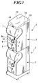
- the automatic vending machine 1 shown in FIG. 1 is such that, for example, merchandise A (hereinafter, capsulated merchandise A) which is capsulated, is contained in a box 2, and after a predetermined coin is inserted in a coin slot 3 disposed in a front side of the box 2, by a person rotating a handle 4, discharges the capsulated merchandise A in the box 2 from a merchandise discharging opening 5 disposed in the front side of the box 2.
- the automatic vending machine 1 shown in FIG. 1 has the boxes 2 double layered, wherein a base on casters is attached under the lower box 2, and a top panel 10 is attached on the upper box 2.
- the box 2 has a box body 6, a lid 7 to cover a merchandise supply opening 6a in a front side of the box body 6, an operation board 8a which composes a part of a front panel 8 disposed on the lower front side of the box body 6 and which has a coin sorting unit 9 on the back side of the operation board 8a, and a top panel 10 which covers the top surface of the box body 6.
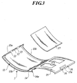
- the lid 7 is made of transparent plastic, and as shown in FIG. 3 , is formed to bulge forward.
- the lid 7 is provided with walls 11 extending backward from the outer edges of the lid 7 comprising an upper edge wall 11a and side walls 11b. Further, in the center in the width direction of the upper edge wall 11a of the lid 7, an elongate hole 12 is formed in the width direction of the box 2. In the upper edge wall 11a of the lid 7, also small holes 13 are formed to sandwich the elongate hole 12.
- a retaining panel 15 which is bulging forward in the same manner as the lid 7 is rotatably attached with respect to a base portion (lower edge of the bend) of the lid 7.
- Pins 16 are provided to protrude upward from the upper edge of the retaining panel 15.
- a handle 15a is provided to protrude rearward.
- the retaining panel 15 is fixed in alignment with the lid 7 by holding a display 17 such as a point-of-purchase display is held between the retaining panel 15 and the lid 7 and fitting the pins 16 into the small holes 13 of the lid 7,.
- the display 17 may be removed by holding the lid 7 with one hand while laying the other hand on the handle 15a and pulling the handle 15a, to let the free end of the retaining panel 15 to disengage from the lid 7.
- Under the bend of the lid 7, a flexion 14 extending downward is provided. On the right and left sides of the lower edge of the flexion 14, protrusions 14a are formed.
- a long groove 18b is formed in the width direction.
- the long groove 18b is where the flexion of the lid 7 is placed, and is formed to be of the size and shape to allow rising and tilting of the lid 7.
- a locking piece 18c is disposed in the center in the width direction of the upper surface of the operation board 8a.
- a locking piece 18c is disposed on the upper surface of the operation board 8a. The locking piece 8c is for stopping the upward movement of the closed lid 7.
- the lower edge of the bend of the lid 7 be formed to have a curvature different from other parts of the bend, so as to let the lower edge of the flexion of the lid 7 be of the shape that would be locked well by the locking piece 18c.
- the protrusions 14a formed on the flexion of the lid 7 seat below the upper wall of the operation board 8a.
- the lid 7 is thereby locked at the operation board 8a. It is preferable that a portion for laying one's hand on be formed on the front side of the lid 7 so that it is easy to pull down the lid 7 when removing the lid 7 from the box body 6.
- a lock 19 is provided above the merchandise supply opening 6a of the box body 6.
- the lock 19 includes a lock body 19a and a key 19b.
- the lock body 19a includes a cylinder 19c, a rotor 19d and locking pieces 19e, 19f.
- the lock body 19a is detachably held by a attachment piece 19g.
- the locking piece 19e and the locking piece 19f are, thought not limited to, integrated in the present embodiment.
- the attachment method of the lock body 19a to the attachment piece 19g will be explained.
- the locking pieces 19e, 19f should be removed beforehand.
- the lock body 19a thus prepared is pushed in a dent 19h on the front side of the attachment piece 19g.
- a locking portion (not shown) on the outer periphery of the cylinder 19c then hits the bottom of the dent 19b, stopping the lock body 19a being pushed further.
- the cylinder 19c partially projects from the back of the attachment piece 19a.
- the attachment structure of the attachment piece 19g will be explained. Nails 19k, 19k are provided on the right and left sides of the attachment piece 19g. Meanwhile, a dent 191 is formed on the box body 6 for the attachment piece 19g to fit in. Further, holes 19m, 19n are formed in the bottom of the dent 191.
- the locking pieces 19e, 19f should be turned horizontally beforehand, as shown in FIG. 5A .
- the attached piece 19g is inserted in the dent 191 with the locking pieces 19e, 19f facing the dent 19l,.
- the attachment piece 19g is attached to the box body 6. Meanwhile, when removing the attachment piece 19g from the box body 6, the attachment piece 19g should be pushed out manually from the inside of the box body 6 while the locking pieces 19e, 19f are turned horizontally.
- the lid 7 is directly locked to the box body 6 by using the locking piece 19e of the lock 19 in the present embodiment, where the box body 6 can be provided with a movable member capable of taking a locking position and an unlocking position of the lid 7, the lid 7 may be indirectly locked to the box body 6 by locking the movable member at the locking position by using the lock 19.
- the locking piece 19f is additionally entered into the elongate hole (not shown) in the upper wall of the box body 6 to lock the lid 7 to the box body 6 in the present embodiment, it may be that only the locking piece 19e be entered into the elongate hole 12 in the lid 7.
- the upper wall 6b may be of a double layered structure so as to let the locking piece 19f enter the elongate hole in the lower layer of the upper wall, or else, a locking piece on which an elongate hole is formed may be provided on the lower side of the upper wall 6b.
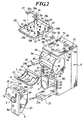
- the operation board 8a as shown in FIG. 2 , is of an inverted L-shaped structure when viewed from the front.
- the operation board 8a is attached detachably to the box body 6.
- the FIG. 2 shows the operation board 8a being removed from the box body 6.
- the front panel 8 of the box body 6 has a cutout 20 of the same shape as the operation board 8a.
- dented strips 23 are formed at a predetermined interval in the vertical direction.
- protruding strips 22 are formed facing inward in the horizontal direction at an appropriate interval in the vertical direction.
- the operation board 8a In order to attach the operation board 8a to the box body 6, having removed the lid 7 from the box body 6, the operation board 8a is lifted above the bottom of the cutout 20, then fit into the cutout 20, and slid down to engage the protruding strips 22 with the dented strips 23, thereby attaching the operation board 8a to a predetermined position of the box body 6.
- the operation board 8a is provided with a connector (not shown) connectable with a connector 6c of the box body 6.
- a locking piece 8b is provided on the right and left walls of the operation board 8a, to retain the operation board 8a in a state slightly lifted above the bottom of the cutout 20.
- the locking piece 8b contacts with a protrusion 8d which is biased by a spring 8c and is disposed on one of the walls that define the cutout 20.
- the operation board 8a is thus retained in a state slightly lifted above the bottom of the cutout 20.
- the retaining strength of the locking piece 8b is not very strong.
- the operation board 8a and a below-mentioned compartment panel 25 are each provided with a locking section 57 to lock the operation board 8a to the box body 6.
- the two locking sections 57 are structured in the same manner, the structure thereof will be explained by taking the locking section 57 on the compartment panel 25 as an example.
- the locking section 57 is provided with a locking pin 57b which is moved by the operation of an operation portion 57a.
- the locking section 57 stops the upward movement of the operation board 8a.
- the locking pin 57b which is projected by the operation of the operation portion 57a fits in an unshown dent provided in the box body 6.
- the above described locking sections 57 are not indispensable. This is because with the operation board 8a attached, the lid 7 attached, and the lid 7 fixed to the box body 6 by the rotation of the key 19b, the upward movement of the operation board 8a is restricted by the lid 7, thereby making the operation board 8a irremovable. Nonetheless, the locking section 57 ensures the operation board 8a being fixed to the box body 6 with extra firmness.
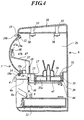
- the compartment panel 25 is disposed to separate the box body 6 into upper and lower parts. Above the compartment panel 25 is a merchandise storage space 26. On the compartment panel 25, a circular recess 27 is formed as shown in FIG. 4 and FIG. 7 . In the bottom of recess a merchandise discharging hole 28 is formed. In the recess 27, a discharge merchandise holding member 34 is mounted. Further, in the bottom of the recess 27, a later described upcoming merchandise detecting section 70 is disposed. Also in the bottom of the recess 27, a rectangular hole 43 is formed to expose a gear 44.
- the discharge merchandise holding member 34 is composed of a drum 35 and an adapter 37.
- the drum 35 may be without a regulatory panel 36.
- a plurality of (four in the embodiment) merchandise holding holes 35a for holding merchandise with a relatively large diameter (for example, capsulated merchandise) are formed at regular intervals.
- a rack 38 is formed on the periphery of the lower surface of the drum 35.
- the gear 44 as shown in FIG. 4 , is connected with a handle 4 via a shaft 45, gears 46, 24, and a shaft 4a. Therefore, when the handle 4 rotates, the rotational 22 force of the handle 4 is transmitted to the drum 35 via the shaft 4a, the gears 24, 46, the shaft 45, the gear 44 and the rack 38, to rotate the drum 35.
- the rotational angle of the drum 35 is 360 / (the number of the merchandise holding holes 35a) degrees. Every time the handle 4 is turned about one turn, the merchandise holding holes 35a aligns with the merchandise discharging hole 28, thereby discharging one by one the merchandise held in the merchandise holding hole 35a.
- a dent 39 which functions in the same manner as ratchet teeth is formed.
- a rectangular hole 29 is formed on a portion of a peripheral wall that defines the recess 27, a rectangular hole 29 is formed.
- a ratchet piece 30 which functions in the same manner as a ratchet pawl is disposed to be freely movable in and out of the rectangular hole 29.
- the dent 39 of the drum 35 engages with the ratchet piece 30 which is biased by an unshown spring in the projecting direction, and which prevents the inverse rotation of the drum 35.
- the drum 35 includes the regulatory panel 36.
- the regulatory panel 36 is disposed on a drum body.
- the regulatory panel 36 is rotatably structured within a predetermined angle around the shaft of the drum 35.
- holes 36a having the same shape as the merchandise holding hole 35a are formed in the circumferential direction in the same number and pitch as the merchandise holding hole 35a.
- the holes 36a of the regulatory panel 36 function to change the diameters of the merchandise holding holes 35a in accordance with the rotational amount of the regulatory panel 36.
- a rib 36b stands to lead outward in the radius direction the merchandise stored above.
- the rib 36a is provided with four springs 36g projecting outward and upward to stir the merchandise stored above.
- the drum 35 and the regulatory panel 36 are combined together by a screw 40.
- the drum body has a insertion hole 35b into which a shaft of a male thread 40a is inserted, and a counterbore 35c in which the nut 40b is seated.
- the regulatory panel 36 has a circular arc shaped insertion hole 36d into which the shaft of the male thread 40a is inserted and which allows the rotational movement of the regulatory panel 36 against the drum body, as well as a circular arc shaped counterbore 36c in which the head of the male thread 40a and a washer are seated, and which allows the rotational movement of the regulatory panel 36 against the drum body.
- the drum body has an insertion hole 35c into which a shaft 41a of a knob 41, and a counterbore 35c in which a coil spring 42 is seated, the coil spring 42 biasing downwards a nut 41b which is screwed to the lower end of the shaft 41a of the knob 41.
- the regulatory panel 36 has a circular arc shaped insertion hole 36e into which the shaft 41a of the knob 41, and which allows the rotational movement of the regulatory panel 36 against the drum body, as well as a counterbore 36f which is formed on both ends of the circular arc shaped insertion hole 36e, and in which a brim 41c of the knob 41 is seated.
- the knob 41 To move the position of the knob 41 from one hole 36f to the other hole 36f, the knob 41 should be pulled up against the biasing force of the coil spring 42 to once remove the brim 41c from the counterbore 36f, while rotating the regulatory panel 36 with respect to the drum body in one direction so as that the knob 41 moves along the insertion hole 36c, and then drop the brim 41c into the other counterbore 36f.
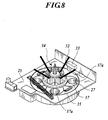
- the adopter 37 is attachable to and detachable from the drum 35. As shown in FIG. 7 , the adopter 37 is provided with merchandise holding holes 37a having a diameter smaller than the merchandise holding holes 35a and a shape with the outer portion being partially cut off. The merchandise holding holes 37a are formed in the circumferential direction of the adopter 37 in the same number as the merchandise holding holes 35a at regular intervals.
- the springs 36g When attaching the adopter 37 to the drum 35, having aligned the merchandise holding holes 35a of the drum 35 with the holes 36a of the regulatory panel 36, the springs 36g should be collected above the drum 35 to insert from below the springs 36g into the hole 37 in the center of the adopter 37, fit the rib 36b in the hole 37c, so that a cylindrical portion 37b on the lower surface of the adopter 37 falls into the merchandise holding holes 35a. Then, as shown in FIG. 8 , the merchandise holding holes 37a and the edge portion thereof fit into the merchandise holding holes 35a.
- the use of the adopter 37 enables handling of the merchandise with even smaller diameter than when using the regulatory panel 36.
- a cutout 31 is formed in the upper edge of the recess 27.
- the cutout 31 is provided with a freely protruding locking piece 32.
- a guide piece 33 is disposed to limit the upward movement of the locking piece 32.
- the locking piece 32 locks the drum 35 in the recess 27 as shown in FIG. 8 by protruding to the position above the drum 35 while the drum 35 is placed in the recess 27. Meanwhile, when the locking piece 32 is removed from the position above the drum 35, the drum 35 is released from the lock and can be taken out of the recess 27.
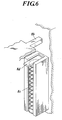
- a guide plate 47 is disposed inside the box body 6.
- the guide plate 47 is bent.
- the lower end of the guide plate 47 is attached to the compartment panel 25 via a coil spring 49.
- the standing portion of the upper end of the guide plate 47 is provided with a dent 47a which is an inner facing opening and which engages with protrusions 48 on the inner walls on the right and the left of the merchandise supply opening 6a.
- the guide plate 47 is retained on a slant towards the compartment panel 25 from the middle portion of the merchandise supply opening 6a.
- the guide plate 47 can be pulled down to the front to broaden the merchandise supply opening 6a, thereby making it easy to supply merchandise and to implement maintenance of the inside of the box body 6.
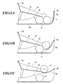
- FIG. 11A to FIG. 11C show the inner structure of the merchandise discharging opening 5.
- the front panel 8 of the merchandise discharging opening 5 is provided with a lid 5a to open and close the merchandise discharge opening 5.
- the lid 5a is structured to rotate inwards of the box body 6.
- the discharging mechanism includes a stopper 5f located on a bottom wall 6d, and a shooter 5c disposed above the stopper 5f.
- the shooter 5c is attached to the box body 6 so that the shooter 5c can rotate about a shaft 5d.
- the shooter 5c has an approximately L-shaped bottom wall 5e.
- the shooter 5c receives the capsulated merchandise A which is dropped from the merchandise discharging hole 28 formed in the recess 27 of the compartment panel 25, and then guides the capsulated merchandise A to the merchandise discharging opening 5.
- the depth from the lid 5a to the stopper 5b is about the size which allows two pieces of capsulated merchandise A to be stored.
- the width of the merchandise discharging opening 5 is about the size which allows one piece of capsulated merchandise A to be stored.
- the tip of the side wall of the shooter 5c contacts the lid 5a at some point from which the shooter 5c and the lid 5a scoop together the capsulated merchandise A, completely opening up the merchandise discharging opening 5.
- the capsulated merchandise A laying on the bottom wall 6d is then to be taken out.
- the lid 5a is closed once, because the capsulated merchandise A which had been previously scooped up is now dropped from the lid 5a, the capsulated merchandise A can be taken out when the lid 5a is reopened. According to this merchandise discharging mechanism, even if there are plural pieces of capsulated merchandise A as shown in FIG. 11A , it is ensured that the lid 5a can be opened up and the merchandise can be taken out.
- the lower portion of the lid 5a is bent in towards to the box body, the same functions may be realized also by forming a rib (protruding piece or some other protruding portion) inside the lid 5a, bending the inner side of the rib, or forming a hock portion on the rib.
- a rib protruding piece or some other protruding portion
- a coin collecting box 21 is disposed in the bottom of the box body 6, behind the cutout 20, in the bottom of the box body 6, behind the cutout 20, a coin collecting box 21 is disposed.
- the coin collecting box 21 can be pulled out to the front and removed from the box body 6.
- the coin collecting box 21 can be fixed to the box body 6 by the lock 21a.
- the coin collecting box 21 is to be attached and removed from the box body 6 with the operation board 8a retained slightly above the bottom of the box body 6, or with the operation board 8a completely removed from the box body 6.
- the operation board 8a is attached to the box body 6, the coin collecting box 21 attached to the box body 6 is completely covered and non-viewable from the front.
- FIG. 1 shows the top panel 10 being attached to the box body 6, while FIG. 2 shows the top panel 10 removed from the box body 6.
- FIG. 2 shows the top panel 10 turned inside out.
- tongue pieces (insertion portion) 53 are disposed perpendicularly downward and in the tip of each of the tongue pieces a hole (locking hole) 54 is formed.
- a hole (locking hole) 54 is formed in the upper wall 6b to which the top panel 10 is attached.
- rectangular holes (insertion hole) 52 for example, are formed.
- the top panel 10 is seated on the box body 6 when the tongue pieces 53 of the top panel 10 are inserted in the holes 52 of the upper wall 6b.
- locking members 58 are attached.
- the locking members 58 are insertable in the holes 54 of the tongue pieces 53 that are inserted in the holes 52. That is, as shown in FIG. 12 , the locking members 58 have shafts 58a and operation portions 58b.
- the locking members 58 are attached to the box body 6 so as to be movable back and forth in the direction perpendicular to the direction of the tongue pieces 53 of the top panel 10. Here, the movement direction aligns with the shaft line direction of the shafts 58a. Further, each of the locking member 58 is rotatable about the shaft line of the shaft 58a when the shaft 58a is inserted in the hole 54.
- the attachment structure of the top panel 10 as described above has the following advantages. Although two boxes 2 are piled in the present embodiment, by disposing the tongue pieces 53 on the lower surface of the upper box 2, that are similar with those on the top panel 10, the boxes 2 can be piled up easily in the same manner as in attaching the top panel 10.
- a display box (display case) can be provided easily in same manner as in attaching the top panel 10.
- the merchandise inside can be displayed using the display box, to let a customer know what kind of merchandise is in that automatic vending machine 1.
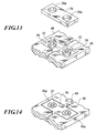
- the automatic vending machine 1 is provided with a coupling block 56 as shown in FIG. 2 , FIG. 13 and FIG. 14 .
- the coupling block 56 has two holes (engaging portion) 56a.
- the holes 56a of the coupling block 56 are fit in a cutout 50 of each of the box body 6, with a boss (engaging portion) 51 of each of the box body 6 fitted in, after which the top panel 10 of each of the box body 6 is attached.
- a cutout 10a of an end plate 10 can be filled by fitting a block 55 which has one hole 55a into the boss 51 of the box body 6.
- the blocks 55, 56 can be stored with the holes 55a, 56a fitted with bosses 10b standing on the back surface of the top panel 10 or between ribs 10c standing on the back surface of the top panel 10.
- the base be also coupled.
- a clip which can hold the side walls of the bases, or the like is used.
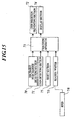
- the automatic vending machine 1 includes a discharge merchandise detecting section 70 to detect merchandise to be discharged and output a signal of the detection, a coin detecting section 71 to detect whether the machine 1 is full of inserted coins and output a signal of the detection, a display section 74 to display the total number of discharge or other various information, a processing apparatus 73 to control a coin insertion preventing section 72 on the basis of the detection signals outputted from the discharge merchandise detecting section 70 and the coin detecting section 71, and a reset section 75.
- a discharge merchandise detecting section 70 to detect merchandise to be discharged and output a signal of the detection
- a coin detecting section 71 to detect whether the machine 1 is full of inserted coins and output a signal of the detection
- a display section 74 to display the total number of discharge or other various information
- a processing apparatus 73 to control a coin insertion preventing section 72 on the basis of the detection signals outputted from the discharge merchandise detecting section 70 and the coin detecting section 71
- a reset section 75
- the discharge merchandise detecting section 70 is composed of, for example, a photo sensor and the like. As explained above, the discharge merchandise detecting section 70 is located in the bottom portion of the recess 27. The position of the discharge merchandise detecting section 70 is directly under the merchandise holding hole 35a which is presently not in alignment with the merchandise discharging hole 28 but would come in alignment with the merchandise discharging hole 28 when the drum 35 rotates accompanying the next rotation of the handle 4. Hereinbelow, the merchandise holding hole 35a in this position will be referred to as the next merchandise holding hole 35a.
- the processing apparatus 73 controls the coin insertion preventing section 72 to prevent insertion of the coins.
- a discharge merchandise detecting section may be provided to detect the merchandise actually discharged through the merchandise discharging hole 28, or to detect the rotation of the drum 35 and determine the number of discharged merchandise on the basis of the detection signal.
- a pocket 25a having a lid is provided for installing a discharge merchandise detecting section having a protrusion that is made to contact the peripheral surface of the drum 35 by a spring and to slide thereon as the drum 35 rotates.
- the display section 74 is composed of, for example, a liquid crystal display section.
- a RFID (Radio Frequency Identification) 78 When a RFID (Radio Frequency Identification) 78 is brought close to a predetermined portion of the operation board 8a, the reader 77 reads off the ID of the RFID, and when that ID is found to comply with the automatic vending machine 1, the processing apparatus 7 makes the display section 74 display the total number of discharged merchandise for a predetermined period of time (for example, for 30 seconds).
- the display section 74 may display other information than the total number of discharged merchandise.
- a rotation detecting section may be provided separately to detect a rotation of the handle 4, to make the display section 74 display, when the handle 4 rotates, a predetermined motion display, or for example, a daily fortune-telling.
- the display section 74 may be used to display "Sold Out” or the like.
- actuation of another switch may be made necessary.
- the merchandise discharging opening 5 may be provided with a switch which may be actuated only when the lid 4a is turned to the back more than necessary (further back than when taking out the merchandise), as the lid 4a contacts the switch there.
- the reset section 75 is disposed on the back side of the operation board 8a, so that the reset section 75 is inoperable from the outside of the box body 6.
- the reset section 75 is operated, the total number of discharging merchandise that has been counted and stored in the memory unit of the processing apparatus 73 is reset.
- the processing apparatus 73 counts again the total number of discharging merchandise since the reset section is operated.
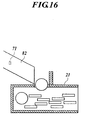
- the coin detecting section 71 is composed of, for example, a photo sensor or the like.
- the coin detection section 71 is disposed, as shown in FIG. 16 , in a coin introducing path which is located on the operation board 8a and which is for introducing coins to a coin collecting box 21.
- the coin detecting section 71 detects whether a coin is remaining in the coin introducing path.
- the coin detecting section 71 outputs a signal, which indicates that the machine is full, to the processing apparatus 73.
- the processing apparatus 73 controls the coin insertion preventing section 72 to prevent a coin being inserted.
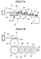
- the coin insertion preventing section 72 is, as shown in FIG. 17A and FIG. 17B , includes a motor 80, a gear mechanism 81 moved by the motor 80, a protrusion 83a which is moved by the gear mechanism 81 to close the coin introducing path 82.
- the gear mechanism 81 is composed of gears 81a to 81j and a rack 81k. Motor power is transmitted to a rack member 83 via the gears 81a to 81j and the rack 81k, and the protrusion 83a disposed on the rack member 83 protrudes to close the coin introducing path 82. Insertion of a coin is thus prevented.
- the reference numeral 84 indicates a clutch, and the gear 81i is pressed on the gear 81h by the biasing force of the coil spring 85, thereby rotating the gear 81i and the gear 81h integrally.
- the gear 81i is overloaded, the gear 81i leaves the gear 81h against the biasing force of the coil spring 85 and releases the connection between the protrusion 83a and the motor 80.
- the total number of discharged merchandise and other merchandise data may be stored in a semiconductor memory of RFID disposed in the box 2, and perform merchandise management by reading out the total number of discharged merchandise and other merchandise data stored in a semiconductor memory with an external reader.
- the merchandise to be discharged may be detected by the discharge merchandise detecting section, and the total number of discharged merchandise determined from the detecting signal may be stored in the semiconductor memory.
- the results counted by the processing apparatus may be stored in the semiconductor memory, or otherwise apply a different counting means.
- the time of sales may be stored.
- a mounting box 47b is disposed on the back side of the standing portion in the upper end of the guide plate 47, so that the RFID can be retrofitted therein.
- the present invention can be appropriately applied to an automatic vending machine without an external electric power source in performing a predetermined display in a manner viewable from the outside at a preset occasion.
Landscapes
- Physics & Mathematics (AREA)
- General Physics & Mathematics (AREA)
- Business, Economics & Management (AREA)
- Engineering & Computer Science (AREA)
- Accounting & Taxation (AREA)
- Computer Networks & Wireless Communication (AREA)
- Strategic Management (AREA)
- General Business, Economics & Management (AREA)
- Theoretical Computer Science (AREA)
- Control Of Vending Devices And Auxiliary Devices For Vending Devices (AREA)
Applications Claiming Priority (2)
| Application Number | Priority Date | Filing Date | Title |
|---|---|---|---|
| JP2004369485A JP4814516B2 (ja) | 2004-12-21 | 2004-12-21 | 自動販売機 |
| PCT/JP2005/023484 WO2006068176A1 (ja) | 2004-12-21 | 2005-12-21 | 自動販売機 |
Publications (3)
| Publication Number | Publication Date |
|---|---|
| EP1837834A1 EP1837834A1 (en) | 2007-09-26 |
| EP1837834A4 EP1837834A4 (en) | 2008-10-29 |
| EP1837834B1 true EP1837834B1 (en) | 2012-01-11 |
Family
ID=36601774
Family Applications (1)
| Application Number | Title | Priority Date | Filing Date |
|---|---|---|---|
| EP05820141A Expired - Lifetime EP1837834B1 (en) | 2004-12-21 | 2005-12-21 | Automatic vending machine |
Country Status (10)
| Country | Link |
|---|---|
| US (1) | US20080135374A1 (cg-RX-API-DMAC7.html) |
| EP (1) | EP1837834B1 (cg-RX-API-DMAC7.html) |
| JP (1) | JP4814516B2 (cg-RX-API-DMAC7.html) |
| KR (1) | KR101313826B1 (cg-RX-API-DMAC7.html) |
| CN (1) | CN101084530B (cg-RX-API-DMAC7.html) |
| AU (1) | AU2005320147B2 (cg-RX-API-DMAC7.html) |
| CA (1) | CA2590466C (cg-RX-API-DMAC7.html) |
| ES (1) | ES2377025T3 (cg-RX-API-DMAC7.html) |
| TW (1) | TW200632793A (cg-RX-API-DMAC7.html) |
| WO (1) | WO2006068176A1 (cg-RX-API-DMAC7.html) |
Families Citing this family (15)
| Publication number | Priority date | Publication date | Assignee | Title |
|---|---|---|---|---|
| US7469779B2 (en) | 2003-06-24 | 2008-12-30 | Bobrick Washroom Equipment, Inc. | Coin drop mechanism |
| US7934646B2 (en) * | 2008-06-25 | 2011-05-03 | International Currency Technologies Corporation | Face panel assembly with an RFID module |
| EP2469487A3 (en) * | 2009-07-01 | 2012-07-18 | Bobrick Washroom Equipment, Inc. | Vending apparatus and method |
| KR100987953B1 (ko) * | 2010-04-15 | 2010-10-18 | 주식회사 에스아이티코리아 | 카지노칩 식별 모듈을 포함하는 카지노칩 교환기기 |
| JP4936576B1 (ja) * | 2012-01-19 | 2012-05-23 | 株式会社バンダイ | 手動商品販売装置 |
| JP5702842B1 (ja) * | 2013-10-08 | 2015-04-15 | 株式会社バンダイ | 物品排出装置 |
| FR3040520B1 (fr) * | 2015-08-31 | 2019-03-22 | Allier Bois Energie | Distributeur de produits en vrac et procede d'utilisation correspondant |
| KR101712777B1 (ko) * | 2016-08-11 | 2017-03-22 | 최성민 | 물품의 자동판매기 |
| CN108376443B (zh) * | 2018-04-20 | 2021-12-21 | 佛山市龙生光启科技有限公司 | 一种自动售卖坚果的自动售货机 |
| JP7141247B2 (ja) * | 2018-05-30 | 2022-09-22 | 株式会社タカラトミーアーツ | 物品排出装置 |
| JP6821750B1 (ja) * | 2019-07-12 | 2021-01-27 | 株式会社バンダイ | 物品供給装置および物品供給システム |
| KR102403136B1 (ko) * | 2022-02-08 | 2022-05-26 | 홍성천 | 캡슐 판매기 |
| KR102414256B1 (ko) * | 2022-02-09 | 2022-06-28 | 황선회 | 운세 캡슐 자동 판매장치 |
| KR102717549B1 (ko) | 2022-09-08 | 2024-10-16 | 주식회사 씨큐프라임 | 반품 기능을 구비한 무인 판매 장치 및 그 방법 |
| JP7730862B2 (ja) | 2023-06-22 | 2025-08-28 | 株式会社バンダイ | 物品供給装置 |
Family Cites Families (26)
| Publication number | Priority date | Publication date | Assignee | Title |
|---|---|---|---|---|
| US3804294A (en) * | 1973-04-06 | 1974-04-16 | Northwestern Corp | Bulk merchandise vending machine with removable cash box and single lock |
| US4037700A (en) * | 1976-06-01 | 1977-07-26 | Heraty Patrick T | Coin vault |
| JPS55100280U (cg-RX-API-DMAC7.html) * | 1978-12-29 | 1980-07-12 | ||
| JPS5953236B2 (ja) * | 1979-01-25 | 1984-12-24 | 住友化学工業株式会社 | 安定な透明液体肥料の製造法 |
| JPS6099509U (ja) * | 1983-12-13 | 1985-07-06 | 三菱電機株式会社 | 風道装置 |
| JPS61109190A (ja) * | 1984-10-31 | 1986-05-27 | エス・ア−ル・デ−株式会社 | 自動販売機管理システム |
| JPS629878A (ja) * | 1985-07-03 | 1987-01-17 | 川崎重工業株式会社 | 液圧式打撃装置 |
| US5091713A (en) * | 1990-05-10 | 1992-02-25 | Universal Automated Systems, Inc. | Inventory, cash, security, and maintenance control apparatus and method for a plurality of remote vending machines |
| US5125492A (en) * | 1991-02-04 | 1992-06-30 | Treleaven David H | Token operated television timer |
| US5131519A (en) * | 1991-10-15 | 1992-07-21 | Corky Ra | Vending machine coin box locking mechanism |
| US5555965A (en) * | 1995-04-17 | 1996-09-17 | Mishina; Koji | Battery operated vending machine for dispensing cylindrical and tetrahedron-shaped objects |
| US5794816A (en) * | 1996-05-03 | 1998-08-18 | Pliler; David B. | Vending machine |
| KR100236591B1 (ko) * | 1996-07-13 | 1999-12-15 | 배길성 | 자동판매기의 수납통 충만 감지 방법 |
| US5831862A (en) * | 1996-08-05 | 1998-11-03 | Mars, Incorporated | Automatic transaction system with a dynamic display and methods of its operation |
| JPH10208119A (ja) * | 1997-01-23 | 1998-08-07 | Shinko Seisakusho Co Ltd | 機械式販売機 |
| US5909795A (en) * | 1997-04-15 | 1999-06-08 | Nova Resolution Industries, Inc. | Combination coin mechanism and coin counter for bulk vending machines |
| US7020680B2 (en) * | 1998-03-19 | 2006-03-28 | Isochron, Llc | System and method for monitoring and control of beverage dispensing equipment |
| US6382387B1 (en) * | 1999-12-16 | 2002-05-07 | Worldwide Integrated Resources, Inc. | Vending machine having a mechanism for preventing a knob from turning and accepting money when the machine is out of product |
| JP3383631B2 (ja) * | 2000-01-27 | 2003-03-04 | 株式会社トミー | 物品排出装置 |
| JP2005525610A (ja) * | 2001-08-07 | 2005-08-25 | マーズ インコーポレイテッド | 販売監査システム |
| US6857710B2 (en) * | 2001-09-18 | 2005-02-22 | The Northwestern Corporation | Secure merchandise-vending machine |
| CA2372995A1 (en) * | 2002-02-25 | 2003-08-25 | Beaver Machine Corporation | Vending machine tracking system |
| JP3492354B2 (ja) | 2002-09-20 | 2004-02-03 | 株式会社トミー | 物品排出装置 |
| US7377065B2 (en) * | 2002-10-23 | 2008-05-27 | Dalb, Inc. | Signage retrofit kit for vending machines |
| JP2004288119A (ja) * | 2003-03-25 | 2004-10-14 | Hitachi Kiden Kogyo Ltd | 入退場者の管理システム |
| US8744622B2 (en) * | 2005-02-22 | 2014-06-03 | Nova Resolution Industries, Inc. | Information management system |
-
2004
- 2004-12-21 JP JP2004369485A patent/JP4814516B2/ja not_active Expired - Lifetime
-
2005
- 2005-12-21 WO PCT/JP2005/023484 patent/WO2006068176A1/ja not_active Ceased
- 2005-12-21 US US11/793,215 patent/US20080135374A1/en not_active Abandoned
- 2005-12-21 CN CN2005800438176A patent/CN101084530B/zh not_active Expired - Lifetime
- 2005-12-21 ES ES05820141T patent/ES2377025T3/es not_active Expired - Lifetime
- 2005-12-21 CA CA2590466A patent/CA2590466C/en not_active Expired - Fee Related
- 2005-12-21 KR KR1020077010776A patent/KR101313826B1/ko not_active Expired - Lifetime
- 2005-12-21 TW TW094145597A patent/TW200632793A/zh not_active IP Right Cessation
- 2005-12-21 AU AU2005320147A patent/AU2005320147B2/en not_active Ceased
- 2005-12-21 EP EP05820141A patent/EP1837834B1/en not_active Expired - Lifetime
Also Published As
| Publication number | Publication date |
|---|---|
| EP1837834A4 (en) | 2008-10-29 |
| AU2005320147A1 (en) | 2006-06-29 |
| TW200632793A (en) | 2006-09-16 |
| JP2006178628A (ja) | 2006-07-06 |
| KR101313826B1 (ko) | 2013-10-01 |
| KR20070090152A (ko) | 2007-09-05 |
| CA2590466C (en) | 2012-09-04 |
| CN101084530B (zh) | 2012-08-22 |
| ES2377025T3 (es) | 2012-03-21 |
| CN101084530A (zh) | 2007-12-05 |
| EP1837834A1 (en) | 2007-09-26 |
| CA2590466A1 (en) | 2006-06-29 |
| US20080135374A1 (en) | 2008-06-12 |
| HK1111257A1 (en) | 2008-08-01 |
| JP4814516B2 (ja) | 2011-11-16 |
| WO2006068176A1 (ja) | 2006-06-29 |
| TWI374404B (cg-RX-API-DMAC7.html) | 2012-10-11 |
| AU2005320147B2 (en) | 2011-08-11 |
Similar Documents
| Publication | Publication Date | Title |
|---|---|---|
| EP1837834B1 (en) | Automatic vending machine | |
| JP5336642B1 (ja) | 遊技媒体貸出機 | |
| JP4435120B2 (ja) | コネクタカバー、及びコネクタカバーを備える遊技台 | |
| JP4528609B2 (ja) | 自動販売機 | |
| JP2878648B2 (ja) | パチンコ台用玉数計数装置 | |
| CN101084531B (zh) | 自动售货机 | |
| JPH10328379A (ja) | 弾球遊技機 | |
| JP4865009B2 (ja) | コネクタカバー、及びコネクタカバーを備える遊技台 | |
| JP4252249B2 (ja) | 遊技機 | |
| JP4528610B2 (ja) | 自動販売機 | |
| JP2008264160A (ja) | コネクタカバー、及びコネクタカバーを備える遊技台 | |
| HK1111257B (en) | Automatic vending machine | |
| JP4708783B2 (ja) | 自動販売機 | |
| JP2006178619A (ja) | 自動販売機 | |
| JP4528686B2 (ja) | 自動販売機 | |
| HK1115663B (en) | Automatic dispenser | |
| JP2008305326A (ja) | 自動販売機 | |
| JP2006178631A (ja) | 自動販売機 | |
| JPH09313716A (ja) | パチンコ台用シャッター | |
| JP2009082214A (ja) | 遊技媒体貸機 | |
| JPH09313727A (ja) | パチンコ台 |
Legal Events
| Date | Code | Title | Description |
|---|---|---|---|
| PUAI | Public reference made under article 153(3) epc to a published international application that has entered the european phase |
Free format text: ORIGINAL CODE: 0009012 |
|
| 17P | Request for examination filed |
Effective date: 20070605 |
|
| AK | Designated contracting states |
Kind code of ref document: A1 Designated state(s): DE ES FR GB IT |
|
| DAX | Request for extension of the european patent (deleted) | ||
| RBV | Designated contracting states (corrected) |
Designated state(s): DE ES FR GB IT |
|
| A4 | Supplementary search report drawn up and despatched |
Effective date: 20080929 |
|
| 17Q | First examination report despatched |
Effective date: 20100218 |
|
| REG | Reference to a national code |
Ref country code: DE Ref legal event code: R079 Ref document number: 602005032205 Country of ref document: DE Free format text: PREVIOUS MAIN CLASS: G07F0009020000 Ipc: G07F0005020000 |
|
| GRAP | Despatch of communication of intention to grant a patent |
Free format text: ORIGINAL CODE: EPIDOSNIGR1 |
|
| RIC1 | Information provided on ipc code assigned before grant |
Ipc: G07F 5/02 20060101AFI20110621BHEP Ipc: G07F 11/44 20060101ALI20110621BHEP Ipc: G07F 9/02 20060101ALI20110621BHEP |
|
| GRAS | Grant fee paid |
Free format text: ORIGINAL CODE: EPIDOSNIGR3 |
|
| GRAA | (expected) grant |
Free format text: ORIGINAL CODE: 0009210 |
|
| RAP1 | Party data changed (applicant data changed or rights of an application transferred) |
Owner name: T-ARTS COMPANY, LTD. |
|
| AK | Designated contracting states |
Kind code of ref document: B1 Designated state(s): DE ES FR GB IT |
|
| REG | Reference to a national code |
Ref country code: GB Ref legal event code: FG4D |
|
| REG | Reference to a national code |
Ref country code: DE Ref legal event code: R096 Ref document number: 602005032205 Country of ref document: DE Effective date: 20120308 |
|
| REG | Reference to a national code |
Ref country code: ES Ref legal event code: FG2A Ref document number: 2377025 Country of ref document: ES Kind code of ref document: T3 Effective date: 20120321 |
|
| PLBE | No opposition filed within time limit |
Free format text: ORIGINAL CODE: 0009261 |
|
| STAA | Information on the status of an ep patent application or granted ep patent |
Free format text: STATUS: NO OPPOSITION FILED WITHIN TIME LIMIT |
|
| 26N | No opposition filed |
Effective date: 20121012 |
|
| REG | Reference to a national code |
Ref country code: DE Ref legal event code: R097 Ref document number: 602005032205 Country of ref document: DE Effective date: 20121012 |
|
| GBPC | Gb: european patent ceased through non-payment of renewal fee |
Effective date: 20121221 |
|
| REG | Reference to a national code |
Ref country code: FR Ref legal event code: ST Effective date: 20130830 |
|
| PG25 | Lapsed in a contracting state [announced via postgrant information from national office to epo] |
Ref country code: DE Free format text: LAPSE BECAUSE OF NON-PAYMENT OF DUE FEES Effective date: 20130702 |
|
| REG | Reference to a national code |
Ref country code: DE Ref legal event code: R119 Ref document number: 602005032205 Country of ref document: DE Effective date: 20130702 |
|
| PG25 | Lapsed in a contracting state [announced via postgrant information from national office to epo] |
Ref country code: FR Free format text: LAPSE BECAUSE OF NON-PAYMENT OF DUE FEES Effective date: 20130102 Ref country code: GB Free format text: LAPSE BECAUSE OF NON-PAYMENT OF DUE FEES Effective date: 20121221 |
|
| PG25 | Lapsed in a contracting state [announced via postgrant information from national office to epo] |
Ref country code: IT Free format text: LAPSE BECAUSE OF NON-PAYMENT OF DUE FEES Effective date: 20121221 |
|
| REG | Reference to a national code |
Ref country code: ES Ref legal event code: FD2A Effective date: 20140306 |
|
| PG25 | Lapsed in a contracting state [announced via postgrant information from national office to epo] |
Ref country code: ES Free format text: LAPSE BECAUSE OF NON-PAYMENT OF DUE FEES Effective date: 20121222 |