EP1837593A2 - Gasarmatur - Google Patents
Gasarmatur Download PDFInfo
- Publication number
- EP1837593A2 EP1837593A2 EP07005424A EP07005424A EP1837593A2 EP 1837593 A2 EP1837593 A2 EP 1837593A2 EP 07005424 A EP07005424 A EP 07005424A EP 07005424 A EP07005424 A EP 07005424A EP 1837593 A2 EP1837593 A2 EP 1837593A2
- Authority
- EP
- European Patent Office
- Prior art keywords
- gas
- gas fitting
- holder
- outlet
- throttle
- Prior art date
- Legal status (The legal status is an assumption and is not a legal conclusion. Google has not performed a legal analysis and makes no representation as to the accuracy of the status listed.)
- Granted
Links
Images


Classifications
-
- F—MECHANICAL ENGINEERING; LIGHTING; HEATING; WEAPONS; BLASTING
- F23—COMBUSTION APPARATUS; COMBUSTION PROCESSES
- F23N—REGULATING OR CONTROLLING COMBUSTION
- F23N1/00—Regulating fuel supply
-
- F—MECHANICAL ENGINEERING; LIGHTING; HEATING; WEAPONS; BLASTING
- F23—COMBUSTION APPARATUS; COMBUSTION PROCESSES
- F23N—REGULATING OR CONTROLLING COMBUSTION
- F23N2227/00—Ignition or checking
- F23N2227/20—Calibrating devices
-
- F—MECHANICAL ENGINEERING; LIGHTING; HEATING; WEAPONS; BLASTING
- F23—COMBUSTION APPARATUS; COMBUSTION PROCESSES
- F23N—REGULATING OR CONTROLLING COMBUSTION
- F23N2235/00—Valves, nozzles or pumps
- F23N2235/12—Fuel valves
- F23N2235/18—Groups of two or more valves
-
- F—MECHANICAL ENGINEERING; LIGHTING; HEATING; WEAPONS; BLASTING
- F23—COMBUSTION APPARATUS; COMBUSTION PROCESSES
- F23N—REGULATING OR CONTROLLING COMBUSTION
- F23N2235/00—Valves, nozzles or pumps
- F23N2235/12—Fuel valves
- F23N2235/24—Valve details
Definitions
- the invention relates to a gas valve with a throttle device for flow limitation.
- the fuel gas amount is adjusted via a gas fitting.
- the gas fitting has at least one safety valve for closing the gas path as well as a proportional valve with which the gas quantity can be adjusted as needed.
- the amount of fuel gas flowing through a gas fitting is dependent on the connection pressure of the fuel gas, the cross section of the flow path, and other factors that influence the flow resistance.
- gas valves are offered in certain performance sizes and limited by nozzles to a specific flow rate. According to EN 483, with fully open valves of a gas fitting and standard connection pressure, the fuel gas quantity must correspond to the target fuel gas quantity +/- 5%.
- Gas fittings have according to the prior art threaded connections at the input and output.
- the nozzles for limiting the fuel gas volume flow are positioned with the interposition of a respective seal between the threaded connection and the connecting pipe connected thereto and fastened by means of a union nut.
- the pressure which is made available to the burner the so-called burner pressure
- the gas connection pressure, as well as the burner pressure can be checked. Therefore, gas fittings usually have measuring points at the input and output.
- the pressure upstream of the throttle which is higher than the burner pressure, is measured at the measuring point at the outlet of the gas fitting. For this reason, it is necessary that there is another measuring point in the connecting tube to the burner for measuring the burner pressure.
- a gas fitting with variable gas nozzle is known, in which there is a measuring point in front of and behind this variable gas nozzle.
- the pressure difference which prevails between the two measuring points, measured and used to adjust the diameter of the variable gas nozzle.
- the invention has for its object to reduce the number of gas pressure measuring points and on the other hand to avoid incorrect measurement.
- an advantageous design of a throttle device according to the invention is protected with a holder.
- the holder of the throttle device generates a greater pressure loss than the nozzle itself and thus the pressure would be further reduced.
- the holder of the throttle device has a removal pin, with which the device can be conveniently removed or used.
- the mounting of the throttle device is flow-optimized.
- the throttle device can be used instead of on the output side of the gas valve on the input side of the gas valve.
- FIG. 1 shows a gas fitting 1 with a first measuring point 3 at the inlet 4.
- a continuous valve 17 In the central area of the gas fitting 1 there is a continuous valve 17 and a safety valve 18.
- the outlet 7 In the region of the outlet 7 there is a second measuring point 6.
- the outlet 7 has a cylindrical cross section on.
- the throttle device 2 On a constriction 12, the throttle device 2 is located with nozzle 19, 10 and connection holder 11.
- the holder 11 closes immediately a seal 13, which separates the gas fitting 1 from a connecting pipe 14.
- Gas fitting 1 and connecting pipe 14 are connected by means of a union nut 16.
- the throttle device 2 has a nozzle 19 with nozzle bore 5, a compound 10 in the form of two connecting struts and a holder 11 in the form of a crossbar, which has the width of the diameter of the output 7. Further, a sampling nozzle 15 is attached to the holder 11.
- the throttle device 2 is inserted into the outlet 7 of the gas fitting 1, so that the throttle device 2 rests on the constriction 12. Then, a seal 13 is placed on the threaded connection 9 at the output 7. Then a connection pipe 14 is laid, which is then tightly connected by means of a union nut 16 with the gas fitting.
- the throttle device 2 can not be erroneously used at the entrance 4.
- the first measuring point 3 is connected to a pressure gauge.
- the second measuring point 6 is connected to a measuring device.
- the union nut 16 is first removed from threaded connection 9 of the gas fitting 1. Then the connecting pipe 14 and the seal 13 are removed. The throttle device 2 can be removed and replaced by another with another nozzle bore 5.
Landscapes
- Engineering & Computer Science (AREA)
- Chemical & Material Sciences (AREA)
- Combustion & Propulsion (AREA)
- Mechanical Engineering (AREA)
- General Engineering & Computer Science (AREA)
- Feeding And Controlling Fuel (AREA)
- Sampling And Sample Adjustment (AREA)
Abstract
Description
- Die Erfindung bezieht sich auf eine Gasarmatur mit einer Drosselvorrichtung zur Durchflussbegrenzung.
- Bei Heizgeräten für gasförmige Brennstoffe wird die Brenngasmenge über eine Gasarmatur eingestellt. Die Gasarmatur verfügt über mindestens ein Sicherheitsventil zum Verschließen des Gasweges sowie ein Proportionalventil, mit dem bedarfsgerecht die Gasmenge eingestellt wird. Die Brenngasmenge, welche durch eine Gasarmatur strömt, ist von dem Anschlussdruck des Brenngases, dem Querschnitt des Strömungswegs sowie anderen Faktoren, welche den Strömungswiderstand beeinflussen, abhängig. Zur Begrenzung der Variantenvielfalt werden Gasarmaturen in bestimmten Leistungsgrößen angeboten und mittels Düsen auf eine konkrete Durchflussmenge begrenzt. Die EN 483 schreibt vor, dass bei voll geöffneten Ventilen einer Gasarmatur und Normanschlussdruck die Brenngasmenge der Soll-Brenngasmenge +/- 5% entsprechen muss.
- Gasarmaturen verfügen gemäß dem Stand der Technik über Gewindeanschlüsse am Ein- und Ausgang. Die Düsen zur Begrenzung des Brenngasvolumenstromes werden unter Zwischenlage jeweils einer Dichtung zwischen dem Gewindeanschluss und dem daran angeschlossenen Anschlussrohr positioniert und mittels einer Überwurfmutter befestigt. Dementsprechend stellt sich der Druck, welcher dem Brenner zur Verfügung gestellt wird, der so genannte Brennerdruck, erst außerhalb der Gasarmatur im Anschlussrohr ein. Zur Überprüfung der Funktionsfähigkeit des Heizgerätes inklusive der Gasarmatur ist es notwendig, dass der Gasanschlussdruck, als auch der Brennerdruck überprüft werden kann. Daher verfügen Gasarmaturen meist über Messstellen am Ein- und Ausgang. Wie jedoch bereits oben beschrieben, wird an der Messstelle am Ausgang der Gasarmatur der Druck vor der Drossel gemessen, welcher höher als der Brennerdruck ist. Aus diesem Grund ist es notwendig, dass im Anschlussrohr zum Brenner eine weitere Messstelle zur Messung des Brennerdrucks vorhanden ist.
- Aus der
AT 406 903 B - Der Erfindung liegt die Aufgabe zugrunde, die Anzahl der Gasdruckmessstellen zu vermindern und andererseits eine Fehlmessung zu vermeiden.
- Erfindungsgemäß wird dies gemäß den Merkmalen des unabhängigen Anspruchs 1 dadurch erreicht, dass die Düse als Teil einer Drosselvorrichtung in der Gasarmatur vor der Messstelle positioniert wird. Hierdurch ist es möglich, an der Messstelle des Gasarmaturenausgangs den Brennerdruck zu messen. Es kann daher auch darauf verzichtet werden, die Messstelle am Ausgang der Gasarmatur zu verplomben oder zu versiegeln, um Fehlmessungen zu vermeiden.
- Gemäß den Merkmalen des abhängigen Anspruchs 2 ist eine vorteilhafte Bauform einer erfindungsgemäßen Drosselvorrichtung mit Halterung geschützt. Gemäß den Merkmalen des abhängigen Anspruchs 3 wird vermieden, dass die Halterung der Drosselvorrichtung einen größeren Druckverlust erzeugt als die Düse selbst und somit der Druck nochmals reduziert würde. Gemäß den Merkmalen des abhängigen Anspruchs 4 verfügt die Halterung der Drosselvorrichtung über einen Entnahmezapfen, mit dem die Vorrichtung bequem entnommen oder eingesetzt werden kann. Gemäß den Merkmalen des anhängigen Anspruchs 5 ist die Halterung der Drosselvorrichtung strömungsoptimiert. Gemäß den Merkmalen des abhängigen Anspruchs 6 wird vermieden, dass die Drosselvorrichtung statt auf der Ausgangsseite der Gasarmatur auf der Eingangsseite der Gasarmatur eingesetzt werden kann.
- Die Erfindung wird nun anhand der Figuren detailliert erläutert. Hierbei zeigen
- Figur 1 eine erfindungsgemäße Gasarmatur mit Drosselvorrichtung im Schnitt,
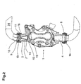
- Figur 2 dieselbe Vorrichtung von der Seite,
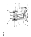
- Figur 3 die Drosselvorrichtung detailliert im Ausgangsbereich der Gasarmatur sowie
- Figur 4 eine perspektivische Ansicht der Drosselvorrichtung.
- Figur 1 zeigt eine Gasarmatur 1 mit einer ersten Messstelle 3 am Eingang 4. Im mittleren Bereich der Gasarmatur 1 befinden sich ein Stetigventil 17 sowie ein Sicherheitsventil 18. Im Bereich des Ausgangs 7 befindet sich eine zweite Messstelle 6. Der Ausgang 7 weist einen zylindrischen Querschnitt auf. Auf einer Verengung 12 liegt die Drosselvorrichtung 2 mit Düse 19, Verbindung 10 und Halterung 11 auf. Der Halterung 11 schließt sich unmittelbar eine Dichtung 13 an, welche die Gasarmatur 1 von einem Anschlussrohr 14 trennt. Gasarmatur 1 und Anschlussrohr 14 sind mittels einer Überwurfmutter 16 verbunden. Die Drosselvorrichtung 2 verfügt über eine Düse 19 mit Düsenbohrung 5, eine Verbindung 10 in Form von zwei Verbindungsstreben sowie eine Halterung 11 in Form eines Querbalkens, welcher die Breite des Durchmessers des Ausgangs 7 aufweist. Ferner ist an der Halterung 11 ein Entnahmestutzen 15 angebracht.
- Zur Montage wird die Drosselvorrichtung 2 in den Ausgang 7 der Gasarmatur 1 eingesetzt, so dass die Drosselvorrichtung 2 auf der Verengung 12 aufliegt. Dann wird eine Dichtung 13 auf den Gewindeanschluss 9 am Ausgang 7 gelegt. Hierauf wird ein Anschlussrohr 14 gelegt, welches anschließend mittels einer Überwurfmutter 16 mit der Gasarmatur dicht verbunden wird.
- Da der Durchmesser der Düse 19 größer als der Querschnitt des Eingangs 4 der Gasarmatur 1 ist, kann die Drosselvorrichtung 2 nicht fälschlicherweise am Eingang 4 eingesetzt werden.
- Zur Messung des Gasanschlussdrucks wird die erste Messstelle 3 mit einem Druckmessgerät verbunden. Zur Messung des Brennerdrucks wird die zweite Messstelle 6 mit einem Messgerät verbunden.
- Soll der maximale Brenngasvolumenstrom verändert werden, so wird zunächst die Überwurfmutter 16 von Gewindeanschluss 9 der Gasarmatur 1 entfernt. Sodann werden das Anschlussrohr 14 und die Dichtung 13 entfernt. Die Drosselvorrichtung 2 kann entnommen werden und durch eine andere mit anderer Düsenbohrung 5 ersetzt werden.
Claims (6)
- Gasarmatur (1) mit Drosselvorrichtung (2) zur Durchflussbegrenzung, einer ersten Messstelle (3) am Eingang (4) der Gasarmatur (1) und einer zweiten Messstelle (6) am Ausgang (7) der Gasarmatur (1), wobei sowohl der Eingang (4), als auch der Ausgang (7) der Gasarmatur (1) über Gewindeanschlüsse (8, 9) verfügt, dadurch gekennzeichnet, dass die Drosselvorrichtung (2) im Ausgang (7) stromauf der zweiten Messstelle (6) im Gasweg positioniert ist, über eine Düse (19) und über eine Verbindung (10) mit einer am Gewindeanschluss (9) des Ausgangs (7) befestigten Halterung (11) verfügt.
- Gasarmatur (1) mit Drossel (2) nach Anspruch 1, dadurch gekennzeichnet, dass die Drosselvorrichtung (2) auf einer Verengung (12) im Ausgang aufliegt und die Halterung (11) an einer Dichtung (13) oder einem Anschlussrohr (14) im Gewindeanschluss (9) des Ausgangs (7) anliegt.
- Gasarmatur (1) mit Drossel (2) nach Anspruch 1 oder 2, dadurch gekennzeichnet, dass die Halterung (11) einen Teil des Querschnitts des Ausgangs (7) abdeckt, wobei vorzugsweise der freie Querschnitt des Ausgangs (7) auf der Höhe der Halterung (11) größer als der freie Querschnitt der Düse (19) ist.
- Gasarmatur (1) mit Drossel (2) nach einem der Ansprüche 1 bis 3, dadurch gekennzeichnet, dass stromab der Halterung (11) ein mit dieser verbundener Entnahmezapfen (15) angeordnet ist.
- Gasarmatur (1) mit Drossel (2) nach einem der Ansprüche 1 bis 4, dadurch gekennzeichnet, dass die Halterung (11) auf der dem Eingang (4) zugewandten Seite über eine Kontur mit geringem Strömungswiderstand verfügt.
- Gasarmatur (1) mit Drossel (2) nach einem der Ansprüche 1 bis 5, dadurch gekennzeichnet, dass der Querschnitt des Eingangs (4) kleiner als der Querschnitt des Ausgangs (7) ist.
Applications Claiming Priority (1)
| Application Number | Priority Date | Filing Date | Title |
|---|---|---|---|
| AT0048506A AT502406B1 (de) | 2006-03-22 | 2006-03-22 | Gasarmatur |
Publications (3)
| Publication Number | Publication Date |
|---|---|
| EP1837593A2 true EP1837593A2 (de) | 2007-09-26 |
| EP1837593A3 EP1837593A3 (de) | 2008-05-21 |
| EP1837593B1 EP1837593B1 (de) | 2015-06-17 |
Family
ID=37776728
Family Applications (1)
| Application Number | Title | Priority Date | Filing Date |
|---|---|---|---|
| EP07005424.2A Active EP1837593B1 (de) | 2006-03-22 | 2007-03-16 | Gasarmatur |
Country Status (4)
| Country | Link |
|---|---|
| EP (1) | EP1837593B1 (de) |
| AT (1) | AT502406B1 (de) |
| DE (1) | DE102007012731A1 (de) |
| ES (1) | ES2547069T3 (de) |
Families Citing this family (1)
| Publication number | Priority date | Publication date | Assignee | Title |
|---|---|---|---|---|
| CN116772422B (zh) * | 2023-07-19 | 2026-07-10 | 上海侨亨实业有限公司 | 一种智能燃气比例阀的控制方法和系统 |
Family Cites Families (4)
| Publication number | Priority date | Publication date | Assignee | Title |
|---|---|---|---|---|
| JPS6018887B2 (ja) * | 1978-04-17 | 1985-05-13 | 松下電器産業株式会社 | 燃焼制御装置 |
| US4850530A (en) * | 1987-12-15 | 1989-07-25 | Johnson Service Company | Gas valve using modular construction |
| DE19639992B4 (de) * | 1995-09-23 | 2007-09-13 | Vaillant Gmbh | Verfahren zum Steuern des Gasdurchsatzes |
| WO2003064928A1 (en) * | 2002-01-29 | 2003-08-07 | Sit La Precisa S.P.A. | A valve unit for modulating the delivery pressure of a gas |
-
2006
- 2006-03-22 AT AT0048506A patent/AT502406B1/de not_active IP Right Cessation
-
2007
- 2007-03-16 DE DE102007012731A patent/DE102007012731A1/de not_active Withdrawn
- 2007-03-16 EP EP07005424.2A patent/EP1837593B1/de active Active
- 2007-03-16 ES ES07005424.2T patent/ES2547069T3/es active Active
Also Published As
| Publication number | Publication date |
|---|---|
| AT502406B1 (de) | 2007-03-15 |
| EP1837593A3 (de) | 2008-05-21 |
| EP1837593B1 (de) | 2015-06-17 |
| ES2547069T3 (es) | 2015-10-01 |
| AT502406A4 (de) | 2007-03-15 |
| DE102007012731A1 (de) | 2007-09-27 |
Similar Documents
| Publication | Publication Date | Title |
|---|---|---|
| DE102004053142B4 (de) | Flanschwirbeldurchflußmesser mit unitären zulaufenden Erweiterungsstücken | |
| DE102008008427B3 (de) | Kalibriervorrichtung zum Kalibrieren eines Gasflussmessers | |
| DE102009046758A1 (de) | Sich selbst überwachende Durchflussmessanordnung und Verfahren zu deren Betrieb | |
| AT521899B1 (de) | Messsystem und Verfahren zur Messung eines Massendurchflusses, einer Dichte, einer Temperatur oder einer Strömungsgeschwindigkeit | |
| DE19635724A1 (de) | Strömungsmesser | |
| EP3997424B1 (de) | Messsystem zur messung eines durchflusses | |
| EP1837593B1 (de) | Gasarmatur | |
| DE202011105809U1 (de) | Vorrichtung zur Messung des Massestroms eines Gases | |
| DE102015001826B3 (de) | Armatur | |
| DE19824098C2 (de) | Vorrichtung zur Erzeugung eines störungsfreien Luftmengenstroms | |
| DE102009060516A1 (de) | Durchflussmengenmessapparatur für Flüssigkeiten | |
| EP0298272A2 (de) | Druckregler für Gase | |
| WO2009077170A1 (de) | Durchflusssensor mit einem in einem kanal hinreichenden auslenkbaren teil | |
| DE2700439A1 (de) | Pneumatische einrichtung zum messen von laengenabmessungen | |
| DE102023118071B3 (de) | Vorrichtung zur Verminderung von Druckstößen | |
| DE102006047880B4 (de) | Durchflußeinstellventil | |
| EP2216637B1 (de) | Messrohr für eine Vorrichtung zur Abtastung eines Strömungsmittels | |
| DE202018006278U1 (de) | Feldgerät und Durchflussmesser für ein Feldgerät | |
| DE10062681A1 (de) | Flüssigkeitsventil für Heiz- und/oder Kühlanlagen | |
| DE102004045733B4 (de) | Vorrichtung zur Differenzdruckmessung in Narkosemitteldosiervorrichtungen | |
| CH628251A5 (en) | Mixing valve for admixing a liquid stream to a gas stream | |
| DE2307188C3 (de) | Zwischen eine eine hinsichtlich des Druckes pulsierende Flüssigkeit aufnehmende Leitung und ein Manometer od. dgl. einsetzbare Vorrichtung | |
| DD143822A1 (de) | Seifenfilmstroemungsmesser-rohr | |
| DE2524506C2 (de) | Drosselorgan einer Luftmengen-Meßeinrichtung | |
| DE102017105191A1 (de) | Armaturen-Baugruppe für flüssige, gasförmige und/oder dampfförmige Medien zum Vorschalten vor eine Armatur, eine Messeinrichtung und/oder ein Leitungssystem-Anbauteil |
Legal Events
| Date | Code | Title | Description |
|---|---|---|---|
| PUAI | Public reference made under article 153(3) epc to a published international application that has entered the european phase |
Free format text: ORIGINAL CODE: 0009012 |
|
| AK | Designated contracting states |
Kind code of ref document: A2 Designated state(s): AT BE BG CH CY CZ DE DK EE ES FI FR GB GR HU IE IS IT LI LT LU LV MC MT NL PL PT RO SE SI SK TR |
|
| AX | Request for extension of the european patent |
Extension state: AL BA HR MK YU |
|
| PUAL | Search report despatched |
Free format text: ORIGINAL CODE: 0009013 |
|
| AK | Designated contracting states |
Kind code of ref document: A3 Designated state(s): AT BE BG CH CY CZ DE DK EE ES FI FR GB GR HU IE IS IT LI LT LU LV MC MT NL PL PT RO SE SI SK TR |
|
| AX | Request for extension of the european patent |
Extension state: AL BA HR MK RS |
|
| 17P | Request for examination filed |
Effective date: 20080520 |
|
| AKX | Designation fees paid |
Designated state(s): AT BE BG CH CY CZ DE DK EE ES FI FR GB GR HU IE IS IT LI LT LU LV MC MT NL PL PT RO SE SI SK TR |
|
| GRAP | Despatch of communication of intention to grant a patent |
Free format text: ORIGINAL CODE: EPIDOSNIGR1 |
|
| INTG | Intention to grant announced |
Effective date: 20150108 |
|
| GRAS | Grant fee paid |
Free format text: ORIGINAL CODE: EPIDOSNIGR3 |
|
| GRAA | (expected) grant |
Free format text: ORIGINAL CODE: 0009210 |
|
| AK | Designated contracting states |
Kind code of ref document: B1 Designated state(s): AT BE BG CH CY CZ DE DK EE ES FI FR GB GR HU IE IS IT LI LT LU LV MC MT NL PL PT RO SE SI SK TR |
|
| REG | Reference to a national code |
Ref country code: GB Ref legal event code: FG4D Free format text: NOT ENGLISH |
|
| REG | Reference to a national code |
Ref country code: CH Ref legal event code: EP |
|
| REG | Reference to a national code |
Ref country code: AT Ref legal event code: REF Ref document number: 732158 Country of ref document: AT Kind code of ref document: T Effective date: 20150715 |
|
| REG | Reference to a national code |
Ref country code: IE Ref legal event code: FG4D Free format text: LANGUAGE OF EP DOCUMENT: GERMAN |
|
| REG | Reference to a national code |
Ref country code: DE Ref legal event code: R096 Ref document number: 502007013981 Country of ref document: DE |
|
| REG | Reference to a national code |
Ref country code: ES Ref legal event code: FG2A Ref document number: 2547069 Country of ref document: ES Kind code of ref document: T3 Effective date: 20151001 |
|
| PG25 | Lapsed in a contracting state [announced via postgrant information from national office to epo] |
Ref country code: LT Free format text: LAPSE BECAUSE OF FAILURE TO SUBMIT A TRANSLATION OF THE DESCRIPTION OR TO PAY THE FEE WITHIN THE PRESCRIBED TIME-LIMIT Effective date: 20150617 Ref country code: FI Free format text: LAPSE BECAUSE OF FAILURE TO SUBMIT A TRANSLATION OF THE DESCRIPTION OR TO PAY THE FEE WITHIN THE PRESCRIBED TIME-LIMIT Effective date: 20150617 |
|
| REG | Reference to a national code |
Ref country code: NL Ref legal event code: FP |
|
| REG | Reference to a national code |
Ref country code: LT Ref legal event code: MG4D |
|
| PG25 | Lapsed in a contracting state [announced via postgrant information from national office to epo] |
Ref country code: BG Free format text: LAPSE BECAUSE OF FAILURE TO SUBMIT A TRANSLATION OF THE DESCRIPTION OR TO PAY THE FEE WITHIN THE PRESCRIBED TIME-LIMIT Effective date: 20150917 Ref country code: GR Free format text: LAPSE BECAUSE OF FAILURE TO SUBMIT A TRANSLATION OF THE DESCRIPTION OR TO PAY THE FEE WITHIN THE PRESCRIBED TIME-LIMIT Effective date: 20150918 Ref country code: LV Free format text: LAPSE BECAUSE OF FAILURE TO SUBMIT A TRANSLATION OF THE DESCRIPTION OR TO PAY THE FEE WITHIN THE PRESCRIBED TIME-LIMIT Effective date: 20150617 |
|
| REG | Reference to a national code |
Ref country code: SK Ref legal event code: T3 Ref document number: E 19297 Country of ref document: SK |
|
| PG25 | Lapsed in a contracting state [announced via postgrant information from national office to epo] |
Ref country code: EE Free format text: LAPSE BECAUSE OF FAILURE TO SUBMIT A TRANSLATION OF THE DESCRIPTION OR TO PAY THE FEE WITHIN THE PRESCRIBED TIME-LIMIT Effective date: 20150617 |
|
| PG25 | Lapsed in a contracting state [announced via postgrant information from national office to epo] |
Ref country code: PT Free format text: LAPSE BECAUSE OF FAILURE TO SUBMIT A TRANSLATION OF THE DESCRIPTION OR TO PAY THE FEE WITHIN THE PRESCRIBED TIME-LIMIT Effective date: 20151019 Ref country code: RO Free format text: LAPSE BECAUSE OF NON-PAYMENT OF DUE FEES Effective date: 20150617 Ref country code: IS Free format text: LAPSE BECAUSE OF FAILURE TO SUBMIT A TRANSLATION OF THE DESCRIPTION OR TO PAY THE FEE WITHIN THE PRESCRIBED TIME-LIMIT Effective date: 20151017 Ref country code: PL Free format text: LAPSE BECAUSE OF FAILURE TO SUBMIT A TRANSLATION OF THE DESCRIPTION OR TO PAY THE FEE WITHIN THE PRESCRIBED TIME-LIMIT Effective date: 20150617 Ref country code: CZ Free format text: LAPSE BECAUSE OF FAILURE TO SUBMIT A TRANSLATION OF THE DESCRIPTION OR TO PAY THE FEE WITHIN THE PRESCRIBED TIME-LIMIT Effective date: 20150617 |
|
| REG | Reference to a national code |
Ref country code: FR Ref legal event code: PLFP Year of fee payment: 10 |
|
| REG | Reference to a national code |
Ref country code: DE Ref legal event code: R097 Ref document number: 502007013981 Country of ref document: DE |
|
| PLBE | No opposition filed within time limit |
Free format text: ORIGINAL CODE: 0009261 |
|
| STAA | Information on the status of an ep patent application or granted ep patent |
Free format text: STATUS: NO OPPOSITION FILED WITHIN TIME LIMIT |
|
| PG25 | Lapsed in a contracting state [announced via postgrant information from national office to epo] |
Ref country code: DK Free format text: LAPSE BECAUSE OF FAILURE TO SUBMIT A TRANSLATION OF THE DESCRIPTION OR TO PAY THE FEE WITHIN THE PRESCRIBED TIME-LIMIT Effective date: 20150617 |
|
| 26N | No opposition filed |
Effective date: 20160318 |
|
| PG25 | Lapsed in a contracting state [announced via postgrant information from national office to epo] |
Ref country code: BE Free format text: LAPSE BECAUSE OF NON-PAYMENT OF DUE FEES Effective date: 20160331 Ref country code: SI Free format text: LAPSE BECAUSE OF FAILURE TO SUBMIT A TRANSLATION OF THE DESCRIPTION OR TO PAY THE FEE WITHIN THE PRESCRIBED TIME-LIMIT Effective date: 20150617 |
|
| PG25 | Lapsed in a contracting state [announced via postgrant information from national office to epo] |
Ref country code: LU Free format text: LAPSE BECAUSE OF FAILURE TO SUBMIT A TRANSLATION OF THE DESCRIPTION OR TO PAY THE FEE WITHIN THE PRESCRIBED TIME-LIMIT Effective date: 20160316 Ref country code: MC Free format text: LAPSE BECAUSE OF FAILURE TO SUBMIT A TRANSLATION OF THE DESCRIPTION OR TO PAY THE FEE WITHIN THE PRESCRIBED TIME-LIMIT Effective date: 20150617 |
|
| REG | Reference to a national code |
Ref country code: CH Ref legal event code: PL |
|
| REG | Reference to a national code |
Ref country code: IE Ref legal event code: MM4A |
|
| PG25 | Lapsed in a contracting state [announced via postgrant information from national office to epo] |
Ref country code: IE Free format text: LAPSE BECAUSE OF NON-PAYMENT OF DUE FEES Effective date: 20160316 Ref country code: LI Free format text: LAPSE BECAUSE OF NON-PAYMENT OF DUE FEES Effective date: 20160331 Ref country code: CH Free format text: LAPSE BECAUSE OF NON-PAYMENT OF DUE FEES Effective date: 20160331 |
|
| REG | Reference to a national code |
Ref country code: FR Ref legal event code: PLFP Year of fee payment: 11 |
|
| PG25 | Lapsed in a contracting state [announced via postgrant information from national office to epo] |
Ref country code: SE Free format text: LAPSE BECAUSE OF FAILURE TO SUBMIT A TRANSLATION OF THE DESCRIPTION OR TO PAY THE FEE WITHIN THE PRESCRIBED TIME-LIMIT Effective date: 20150617 |
|
| PG25 | Lapsed in a contracting state [announced via postgrant information from national office to epo] |
Ref country code: MT Free format text: LAPSE BECAUSE OF FAILURE TO SUBMIT A TRANSLATION OF THE DESCRIPTION OR TO PAY THE FEE WITHIN THE PRESCRIBED TIME-LIMIT Effective date: 20150617 |
|
| REG | Reference to a national code |
Ref country code: FR Ref legal event code: PLFP Year of fee payment: 12 |
|
| PG25 | Lapsed in a contracting state [announced via postgrant information from national office to epo] |
Ref country code: HU Free format text: LAPSE BECAUSE OF FAILURE TO SUBMIT A TRANSLATION OF THE DESCRIPTION OR TO PAY THE FEE WITHIN THE PRESCRIBED TIME-LIMIT; INVALID AB INITIO Effective date: 20070316 Ref country code: CY Free format text: LAPSE BECAUSE OF FAILURE TO SUBMIT A TRANSLATION OF THE DESCRIPTION OR TO PAY THE FEE WITHIN THE PRESCRIBED TIME-LIMIT Effective date: 20150617 |
|
| PG25 | Lapsed in a contracting state [announced via postgrant information from national office to epo] |
Ref country code: TR Free format text: LAPSE BECAUSE OF FAILURE TO SUBMIT A TRANSLATION OF THE DESCRIPTION OR TO PAY THE FEE WITHIN THE PRESCRIBED TIME-LIMIT Effective date: 20150617 |
|
| PGFP | Annual fee paid to national office [announced via postgrant information from national office to epo] |
Ref country code: NL Payment date: 20250225 Year of fee payment: 19 |
|
| PGFP | Annual fee paid to national office [announced via postgrant information from national office to epo] |
Ref country code: DE Payment date: 20250226 Year of fee payment: 19 |
|
| PGFP | Annual fee paid to national office [announced via postgrant information from national office to epo] |
Ref country code: AT Payment date: 20250226 Year of fee payment: 19 |
|
| PGFP | Annual fee paid to national office [announced via postgrant information from national office to epo] |
Ref country code: FR Payment date: 20250326 Year of fee payment: 19 |
|
| PGFP | Annual fee paid to national office [announced via postgrant information from national office to epo] |
Ref country code: SK Payment date: 20250224 Year of fee payment: 19 Ref country code: GB Payment date: 20250226 Year of fee payment: 19 |
|
| PGFP | Annual fee paid to national office [announced via postgrant information from national office to epo] |
Ref country code: ES Payment date: 20250401 Year of fee payment: 19 |
|
| PGFP | Annual fee paid to national office [announced via postgrant information from national office to epo] |
Ref country code: IT Payment date: 20250327 Year of fee payment: 19 |