EP1837252A1 - Bracket for securing side airbag for automotive vehicle - Google Patents
Bracket for securing side airbag for automotive vehicle Download PDFInfo
- Publication number
- EP1837252A1 EP1837252A1 EP07005189A EP07005189A EP1837252A1 EP 1837252 A1 EP1837252 A1 EP 1837252A1 EP 07005189 A EP07005189 A EP 07005189A EP 07005189 A EP07005189 A EP 07005189A EP 1837252 A1 EP1837252 A1 EP 1837252A1
- Authority
- EP
- European Patent Office
- Prior art keywords
- bracket
- side airbag
- plate
- aperture
- fixing
- Prior art date
- Legal status (The legal status is an assumption and is not a legal conclusion. Google has not performed a legal analysis and makes no representation as to the accuracy of the status listed.)
- Withdrawn
Links
- 238000005452 bending Methods 0.000 claims abstract description 19
- 238000009434 installation Methods 0.000 claims description 55
- 238000003780 insertion Methods 0.000 claims description 11
- 230000037431 insertion Effects 0.000 claims description 11
- 239000002184 metal Substances 0.000 claims description 4
- 229910052751 metal Inorganic materials 0.000 claims description 4
- 230000002787 reinforcement Effects 0.000 claims description 4
- 230000000452 restraining effect Effects 0.000 claims description 4
- 238000004519 manufacturing process Methods 0.000 abstract description 14
- 239000000463 material Substances 0.000 description 9
- 239000007789 gas Substances 0.000 description 8
- 210000000038 chest Anatomy 0.000 description 7
- 238000000034 method Methods 0.000 description 7
- 230000008569 process Effects 0.000 description 6
- XEEYBQQBJWHFJM-UHFFFAOYSA-N Iron Chemical compound [Fe] XEEYBQQBJWHFJM-UHFFFAOYSA-N 0.000 description 4
- 230000006378 damage Effects 0.000 description 4
- 229920003023 plastic Polymers 0.000 description 4
- 239000004033 plastic Substances 0.000 description 4
- 208000027418 Wounds and injury Diseases 0.000 description 2
- 230000008901 benefit Effects 0.000 description 2
- 238000005520 cutting process Methods 0.000 description 2
- 239000002360 explosive Substances 0.000 description 2
- 238000001746 injection moulding Methods 0.000 description 2
- 208000014674 injury Diseases 0.000 description 2
- 238000009413 insulation Methods 0.000 description 2
- 229910052742 iron Inorganic materials 0.000 description 2
- 238000012986 modification Methods 0.000 description 2
- 230000004048 modification Effects 0.000 description 2
- LPXPTNMVRIOKMN-UHFFFAOYSA-M sodium nitrite Chemical compound [Na+].[O-]N=O LPXPTNMVRIOKMN-UHFFFAOYSA-M 0.000 description 2
- 238000003466 welding Methods 0.000 description 2
- IJGRMHOSHXDMSA-UHFFFAOYSA-N Atomic nitrogen Chemical compound N#N IJGRMHOSHXDMSA-UHFFFAOYSA-N 0.000 description 1
- 238000010521 absorption reaction Methods 0.000 description 1
- 230000007547 defect Effects 0.000 description 1
- 229910001873 dinitrogen Inorganic materials 0.000 description 1
- 238000005516 engineering process Methods 0.000 description 1
- 239000007769 metal material Substances 0.000 description 1
- 238000003825 pressing Methods 0.000 description 1
- 230000009467 reduction Effects 0.000 description 1
- 235000010288 sodium nitrite Nutrition 0.000 description 1
- 239000007779 soft material Substances 0.000 description 1
- 239000002699 waste material Substances 0.000 description 1
- 239000013585 weight reducing agent Substances 0.000 description 1
Images








Classifications
-
- B—PERFORMING OPERATIONS; TRANSPORTING
- B60—VEHICLES IN GENERAL
- B60R—VEHICLES, VEHICLE FITTINGS, OR VEHICLE PARTS, NOT OTHERWISE PROVIDED FOR
- B60R21/00—Arrangements or fittings on vehicles for protecting or preventing injuries to occupants or pedestrians in case of accidents or other traffic risks
- B60R21/02—Occupant safety arrangements or fittings, e.g. crash pads
- B60R21/16—Inflatable occupant restraints or confinements designed to inflate upon impact or impending impact, e.g. air bags
- B60R21/20—Arrangements for storing inflatable members in their non-use or deflated condition; Arrangement or mounting of air bag modules or components
- B60R21/213—Arrangements for storing inflatable members in their non-use or deflated condition; Arrangement or mounting of air bag modules or components in vehicle roof frames or pillars
-
- Y—GENERAL TAGGING OF NEW TECHNOLOGICAL DEVELOPMENTS; GENERAL TAGGING OF CROSS-SECTIONAL TECHNOLOGIES SPANNING OVER SEVERAL SECTIONS OF THE IPC; TECHNICAL SUBJECTS COVERED BY FORMER USPC CROSS-REFERENCE ART COLLECTIONS [XRACs] AND DIGESTS
- Y10—TECHNICAL SUBJECTS COVERED BY FORMER USPC
- Y10T—TECHNICAL SUBJECTS COVERED BY FORMER US CLASSIFICATION
- Y10T24/00—Buckles, buttons, clasps, etc.
- Y10T24/30—Trim molding fastener
-
- Y—GENERAL TAGGING OF NEW TECHNOLOGICAL DEVELOPMENTS; GENERAL TAGGING OF CROSS-SECTIONAL TECHNOLOGIES SPANNING OVER SEVERAL SECTIONS OF THE IPC; TECHNICAL SUBJECTS COVERED BY FORMER USPC CROSS-REFERENCE ART COLLECTIONS [XRACs] AND DIGESTS
- Y10—TECHNICAL SUBJECTS COVERED BY FORMER USPC
- Y10T—TECHNICAL SUBJECTS COVERED BY FORMER US CLASSIFICATION
- Y10T24/00—Buckles, buttons, clasps, etc.
- Y10T24/47—Strap-end-attaching devices
Definitions
- the present invention relates to a bracket for securing a side airbag for an automotive vehicle and, more particularly, to a bracket for securing a side airbag for an automotive vehicle, which easily secures the side airbag and is prevented from being broken or deformed when it is fastened by a bolt.
- an airbag module installed in an automotive vehicle is a device for maximally protecting an occupant against injury when the automotive vehicle crashes.
- An airbag module is typically installed in or around a steering wheel of a driver seat and in an instrument panel of a passenger seat.
- the airbag module is operatively connected to a safety belt by a crash sensing sensor and an electronic control unit (hereinafter, referred to as "ECU"), and it maximally protects an occupant against injury.
- ECU electronice control unit
- the crash sensing sensor outputs a crash sensing signal to the ECU.
- the ECU determines whether to operate an airbag, depending on the intensity of the crash. If the airbag needs to be operated, the ECU operates an inflator to inflate the airbag.
- the airbag module installed at the side of an automotive vehicle is generally called a 'side airbag.
- the side airbag is installed in an A-pillar which is connected from the front passenger seat to the back seat. When side impact is applied, the side airbag is inflated by the operation of the inflator.
- a side airbag is used for an automotive vehicle, which prevents excessive inflation pressure from being applied to a lower end part of the side airbag to be deployed when the vehicle encounters a side crash, and balances the inflation pressure by an injected gas in a thorax bag and a head bag to reduce shaking when the side airbag is inflated and improves the work efficiency upon manufacture.
- the side airbag comprises: a thorax bag 12 and a head bag 11 to be deployed upon a side crash.
- the thorax bag 12 comprises a mounting part 14 and a lower end part 16.
- the mounting part 14 has a neck shape at a rear side of the thorax bag 12.
- the lower end part 16 is formed at a distance from the mounting part 14.
- An upper part and a lower part of the side airbag are formed symmetrically, based on the center of the mounting part 14.
- a tether 13 is positioned between the thorax bag 12 and the head bag 11.
- a vent aperture is formed in the side airbag at a distance from the mounting part 14.
- a pulling plate 15 is symmetrical with the thorax bag 12, and the thorax bag 12 is extended from the head bag 11.
- the aforementioned side airbag is installed by fastening a bolt to the A-pillar of the automotive vehicle. To install the side airbag onto the A-pillar, additional securing devices are needed.
- brackets each having a securing aperture into which a bolt is inserted, are positioned at predetermined positions of the side airbag and are secured by fastening bolts.
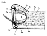
- a bracket 3a with a welding bolt 2a is welded at one side of a back part frame 1 a.
- a back part 7a with a pad 5a covered by a cover 6a is positioned at one side of an installation space 4a of the side airbag.
- each of the airbag housing 8a and the airbag door 9a is positioned inside a support wire 10a, and the other side of each of the airbag housing 8a and the airbag door 9a is fixed to the welding bolt 2a of the bracket 3a.
- the bracket for securing the side airbag is usually made of plastics, the bracket is broken or deformed while the bolt is fastened and therefore, the bracket cannot perform its function. Moreover, since this probiem makes it impossible for the side airbag to be normally operated, an occupant is fatally injured.
- Another conventional side airbag 30 comprises: an airbag which is installed inside a headlining of a roof side panel; an inflator which is installed at one side of the airbag and which has a gas generating material to deploy the airbag upon a side crash; and a guide member with one side end which is connected to the airbag and the other side end which is positioned to pivot around the roof side panel.
- a headlining 21 is composed of plastics which are attached to the ceiling inside an automotive vehicle.
- Basic materials of the headlining 21 are the surface and pad with the functions, such as insulation from the roof, insulation of sound, or absorption of sound inside the vehicle and the like.
- the headlining 21 is formed integrally with these surface and pad.
- an inflator 40 rapidly burns a gas generating material including an element of sodium nitrite, and the like, by using an igniter and simultaneously generates nitrogen gas.
- the inflator 40 is secured to a roof side panel 25 by a separate bracket 41.
- connection strap (hereinafter, referred to as "connection strap") is positioned at the other side of the inflator 40.
- the strap 31 prevents one side of the side airbag 30 from waving when the airbag 30 is deployed by the inflator. This is illustrated in FIG. 2B.
- the conventional side airbag since the conventional side airbag has no specific structure to hold the connection strap, it is troublesome to assemble the side airbag in the A-pillar due to the interference between the A-pillar and the connection strap.
- an operator in a manufacturing site needs to check whether there is the interference with the connection strap when assembling the side airbag in the A-pillar.
- the interference occurs, a process of avoiding the interference is added. As a result, a working time becomes longer and the assembling efficiency is deteriorated.
- a conventional bracket 50 for securing a side airbag has a shape in which a connection strap 52 is connected to a simply long rectangular aperture 51. Therefore, the bracket 50 is not properly connected to the connection strap 52.
- connection strap 52 since the connection strap 52 is movable in the bracket 50, the connection strap 52 turns within the rectangular aperture 51 of the bracket 50, as illustrated in FIG. 3B.
- connection strap 52 inclines towards a lower part of the rectangular aperture 51 as illustrated in FIG. 3C. Consequently, the side airbag is not stably secured.
- connection strap 52 when a connection strap 52 is cut by the friction caused during the accident, the side airbag is not inflated in a normal direction, upon the side crash.
- FIGS. 4A and 4B Another conventional side airbag 60 will be described with reference to FIGS. 4A and 4B.
- the side airbag 60 comprises: a side airbag cushion 61, an inflator 62 supplying a gas to the side airbag cushion 61, a housing receiving the inflator 62, and a diffuser 64 included in the side airbag 60 and supplying a gas, which is generated from the inflator 62, to the side airbag cushion 61.
- the inflator 62 is electrically connected to a control unit (not shown).
- the control unit is connected to a crash sensing sensor (not shown) in an automotive vehicle.
- the side airbag cushion 61 is formed, at predetermined width and length, to sufficiently protect a head part of an occupant of the automotive vehicle.
- a tether 65 is provided in one part of an end of the side airbag cushion 61. The tether 65 guides the side airbag 60 to be broadly inflated lengthwise or widthwise when the side airbag 60 is deployed.
- the diffuser 64 has a tube shape. A number of apertures (not shown) are formed, to be positioned lengthwise, on an outer circumference surface of the diffuser 64. While the diffuser 64 is received inside an upper end part of the side airbag 60, one end of the diffuser 64 is connected to the housing 63 receiving the inflator 62.
- a holder 66 fastens a part of the side airbag 60 which covers the connection part of the diffuser 64 and the housing 63, to be sealed.
- a number of holders 67 are connected to the upper end of the side airbag 60, at a predetermined interval.
- the holders 67 secure the side airbag cushion 61 to a roof rail.
- the holders 67 cover an external surface of a side airbag housing 68 and temporarily hold the side airbag housing 68.
- the side airbag housing 68 covers the side airbag cushion 61 which is folded.
- the holders 67 securing the side airbag 60 are formed of a single material.
- the holders 67 are made of a soft material, an additional component is needed to prevent the holders 67 from being broken when the side airbag 60 is secured to the automotive vehicle by fastening a bolt.
- the holders are made of a hard material to prevent the holders from being broken, there is a difficulty in cutting a cutting part when the side airbag 60 is deployed.
- a space of each holder 67 is narrow and a shape of the holder 67 is gradually narrower downwardly. Therefore, since a region for supporting the side airbag 60 is narrow, many holders 67 are needed. This results in a longer working time in the manufacturing site.
- the present invention is directed to provide a bracket for securing a side airbag for an automotive vehicle, wherein, when the bracket is fastened by a bolt, the bracket is prevented from being broken or deformed, by protecting the bolt fastened bracket formed on a mounting plate, and wherein the side airbag is maintained in the best condition.
- Another object of the present invention is to provide a bracket for securing a side airbag for an automotive vehicle, wherein assembling the side airbag in a manufacturing site is easy, by fixing a path of a connection strap so that the connection strap connecting the side airbag to the bracket is secured against an A-pillar and by removing interference with the connection strap upon the assembling of the side airbag.
- Another object of the present invention is to provide a bracket for securing a side airbag for an automotive vehicle, wherein a connection strap is prevented from affecting a deploying performance of the side airbag, by making it easy for the connection strap to be released from a clip.
- Another object of the present invention is to provide a bracket for securing a side airbag for an automotive vehicle, wherein an operator easily mounts the side airbag in a manufacturing site by preventing a connection strap from turning in an aperture of the bracket used for securing the side airbag, and wherein a failure in a securing structure is prevented.
- Another object of the present invention is to provide a bracket for securing a side airbag for an automotive vehicle, wherein safety of a passenger is improved by normally absorbing side impact applied to the passenger upon an accident, by preventing a connection strip from being inclined towards one side when a bracket of the side airbag is distorted upon a crash, and by enabling a normal operation of the side airbag.
- Another object of the present invention is to provide a bracket for securing a side airbag for an automotive vehicle, wherein an airbag cushion is restrained by one component.
- Another object of the present invention is to provide a bracket for securing a side airbag for an automotive vehicle, wherein the side airbag is simply assembled to be easily secured and the side airbag is easily dissembled without breakage, so that the efficiency in assembling or dissembling the side airbag is improved.
- Another object of the present invention is to provide a bracket for securing a side airbag for an automotive vehicle, wherein the side airbag is stably secured without using any additional components.
- Another object of the present invention is to provide a bracket for securing a side airbag for an automotive vehicle, wherein a cut part is easily parted when the side airbag is deployed, so that the airbag cushion is smoothly deployed.
- Exemplary embodiments of the present invention provide brackets for securing a side airbag for an automotive vehicle.
- a bracket for securing a side airbag for an automotive vehicle comprises: a mounting plate for securing the side airbag to the vehicle, including a body and a connection part formed on the body; and a bracket clip installed on the external surface of the connection part, and wherein the connection part has a through aperture through which a bolt is fastened and protrusions are each formed on each of both side ends of the connection part, and the bracket clip comprises: a bending part formed in the middle of the bracket clip; a plurality of support plates formed at both side of the bending part; and through apertures formed on the support plates, corresponding to the through aperture of the connection part.
- a bracket for securing a side airbag for an automotive vehicle comprises: a bracket for fixing a connection strap which is configured to connect the side airbag to the vehicle, and wherein the bracket comprises: a support plate; an installation plate positioned at a middle upper part of the support plate and including an installation aperture; and a fixing part formed by being forwardly bent from the right and left edges, with respect to the installation plate, of the support plate.
- a bracket for securing a side airbag for an automotive vehicle which connects a connection strap, connected to the side airbag, to a pillar of the vehicle, comprises: an installation aperture to be secured to the pillar; and a fixing bracket aperture through which the connection strap connected to the side airbag passes, and wherein the fixing bracket aperture comprises: a fixing bracket central aperture through which the connection strap passes; and extension apertures formed at both ends of the fixing bracket central aperture and each having a greater width than that of the fixing bracket central aperture.
- a bracket for securing a side airbag for an automotive vehicle which is installed inside a roof side panel, comprises: a lower plate having a lower plate installation aperture and connection hooks each formed at the right and left of the lower plate installation aperture; an upper plate connected to one side of the lower plate and having an upper plate installation aperture and insertion apertures formed at the right and left of the upper plate installation aperture, each insertion aperture to which each connection hook is connected; and an extension plate extended downward the lower plate.
- a bracket for securing a side airbag to an automotive vehicle comprises: a bracket clip made of a metal piece being bent, the bracket clip including a bending part, two support plates formed at either side of the bending part, and installation apertures respectively formed in the support plates; a body of the bracket; and, wherein the body of the bracket comprises: a restraint plate restraining a side airbag housing; a number of restraint members which are extended downwardly from at one side of the restraint plate and cover a side airbag housing, and a hook connection part which is extended and form at ends of the restraint members; and a connection part which is bent to be formed at the other side of the restraint panel and into which the bracket clip is inserted.
- a bracket 100 for securing a side airbag for an automotive vehicle will be described, in detail, with reference to the accompanying drawings.
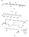
- FIG. 5 shows a state of carrying out a bracket for securing a side airbag for an automotive vehicle according to a first exemplary embodiment of the present invention
- FIG 6 is a perspective view of a bracket clip in the device according to the first exemplary embodiment
- FIGS. 7A and 7B show examples of the bracket according to the first exemplary embodiment.
- a mounting plate 130 is a device for supporting a side airbag 101.
- the mounting plate 130 is installed to be secured to an upper frame (hereinafter, referred to as "A-pillar 110") of lateral windows by a bolt.
- the mounting plate 130 is manufactured by injection molding of plastics in a rectangular form.
- a bent connection part 132 is integrally formed with one side of a rectangular body 131, by injection molding.
- connection part 132 A through aperture (135) through which a bolt(not shown) is fastened is formed in the center of the connection part 132.
- Predetermined protrusions 133 are respectively formed on an external surface of one side of the connection part 132, by protruding both side ends of the connection part 132 at a predetermined height.
- a bracket clip 120 is a nearly rectangular metal plate as illustrated in FIG. 6.
- a bending part 121 is formed in the middle of the bracket clip 120.
- a plurality of support plates 122a and 122b are formed by being folded based on the bending part 121.
- An aperture 124 is formed in each of the support plates 122a and 122b.
- the aperture 124 is aligned with the through aperture (not shown) of the connection part 132.
- a predetermined ring-shaped rise 123 may be formed on an outer circumference of the aperture 124 which is formed on an inner surface of any one (for example, the support plate 122b) among the support plates 122a and 122b.
- the ring-shaped rise 123 is inserted into the through aperture (not shown) of the connection part 132.
- the width of the bracket clip 120 is same as or less than the distance between the protrusions 133.
- the bracket clip 120 is positioned at an external surface of the connection part 132.
- the bracket clip 120 is attached to the connection part 132 by inserting the ring-shaped rise 123 formed on one support plate 122b into the through aperture of the connection part 132 and by folding the other support plate 122a, so that the support plates 122a and 122b cover the external surface of the connection part 132.
- bracket 100 for securing a side airbag for an automotive vehicle As illustrated in FIG. 7B, assembling of the bracket 100 for securing a side airbag for an automotive vehicle according to the first exemplary embodiment of the present invention is completed.
- the bracket 100 for securing a side airbag for an automotive vehicle which is completely assembled in the above-described manner, is installed to be fixed onto the A-pillar 110 of a body of vehicle.
- connection part 132 connected to the bracket clip 120 is positioned at an appropriate position of the A-pillar 110, the bracket 100 for securing a side airbag for an automotive vehicle is secured by fastening the bolts (not shown) which is inserted into the aperture 124 formed on the support plates 122a and 122b of the bracket clip 120 and into the through-hole (not shown) of the connection part 132.
- connection part 132 is prevented from being broken or deformed.
- the side airbag 101 is secured against the lower surface of the body 131 of the mounting plate 130.
- a bracket 200 for securing a side airbag for an automotive vehicle according to a second exemplary embodiment will be described, in detail, with reference to the accompanying drawings.
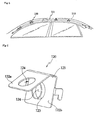
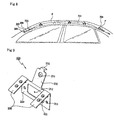
- FIG. 8 is a front view of an installation position of the bracket 200 for securing a side airbag for an automotive vehicle according to the second exemplary embodiment of the present invention.
- a side airbag 201 is mounted inside a roof side panel R of the vehicle.
- One end of the side airbag 201 is secured to a buckle 205 in an A-pillar 202, and the other end thereof is connected to a C-pillar P through an inflator 206.
- the side airbag 201 and the buckle 205 are connected to each other by a connection strap 204.
- the bracket 200 fixing a path of the connection strap 204 is positioned in the middle part of the connection strap 204.
- the side airbag 201 includes a sensor (not shown) for sensing a crash of the vehicle and an electronic control unit for operating the inflator 206 by receiving a signal from the sensor.
- the buckle 205 is fixed to the A-pillar 202 at the front part of the side airbag 201.
- the buckle 205 is connected to the side airbag 201 by the connection strap 204.
- the connection strap 204 is fixed by the bracket 200.
- the inflator 206 including a gas for deploying the side airbag 201 is installed in the rear part of the side airbag.
- FIGS. 9 through 11 are perspective views of a shape of the bracket 200 according to the second embodiment.
- the bracket 200 comprises a support plate 210 and an installation plate 230.
- the installation plate 230 is formed by being bent from the support plate 210.
- An installation aperture 231 is formed in the installation plate 230.
- a bolt is fastened through the installation aperture 231.
- a hook 232 is formed on an upper end of the installation plate 230. The hook 232 makes it easy to be secured when the side airbag 201 is installed in the vehicle.
- the support plate 210 is a part of directly fixing the connection strap 204.
- Fixing plates 220 are respectively formed to be bent at an upper end of both sides of the support plate 210.
- the fixing plates 220 are pressed so that the connection strap 204 is positioned between the fixing plates 220 and the support plate 210. Accordingly, the fixing plates 220, the connection strap 204 and the support plate 210 are secured to one another.
- connection strap 204 Two pairs of fixing protrusions 221 formed on the fixing plates 220 enable the connection strap 204 to be more stably fixed.
- a slimming aperture 212 in a rectangular form is made in the middle of the support plate 210, for cost reduction and weight reduction.
- Two pairs of apertures 211 are formed on both sides of the slimming aperture 212.
- the apertures 211 are positioned so as to correspond to the fixing protrusions 221 of the fixing plates 210, so that the fixing protrusions 221 are respectively inserted into the apertures 211.
- FIG. 10 is a perspective view of a shape of the bracket 200 and the connection strap 204 according to the second exemplary embodiment.
- the fixing plates 220 of the bracket 200 are pressed to be fixed when the fixing plates 220 are assembled with the connection strap 204. Further, the fixing protrusions 221 to be inserted into the apertures 211 of the support plate 210 press the connection strap 204 to be fixed, without interference. Therefore, the security between the connection strap 204 and the fixing plates 220 is increased.
- FIG. 11A is a front view of the bracket 200 and FIG. 11B is a side view of the bracket 200 according to the second exemplary embodiment.
- the fixing plates 220 are bent towards the support plate 210 so that the pressing process is easy upon the assembling.
- the ends of the fixing plates 220 are slightly bent to hold the connection strap 204 downwardly when the fixing plates 220 are pressed to fix the connection strap 204.
- the slightly bending ends of the fixing plates 220 are one-touch connected to the downward edge of the support plate 210, thereby preventing the connection strap 204 from slipping out from the bracket 200.
- FIG. 12 is a perspective view of a bracket 200 for securing a side airbag for an automotive vehicle according to the third exemplary embodiment.
- one of fixing plates 220 in the bracket 200 is bent from an upper end edge of a support plate 210 and the other is bent from a lower end edge of the support plate 210, so that a connection strap 204 is prevented from slipping down.
- FIG. 13 is a perspective view of a bracket 200 for securing a side airbag for an automotive vehicle according to the fourth exemplary embodiment.
- fixing protrusions 221 of fixing plates 220 in the bracket 200 respectively have a square form.
- the fixing plates 220 are cut in the other three sides, except for a lower end, at predetermined positions. The cut three sides in each position are bent to protrude towards the support plate 210, thereby preventing a connection strap 204 from slipping out.
- And holes 211 are formed to connect the fixing protrusions 221 in the support plate 210.
- connection strap 204 which is formed to be extended to a side airbag 201 is fixed by the bracket 200 and the path of the connection strap 204 is fixed. Therefore, there is no interference between the connection strap 204 and the A-pillar when the side airbag 201 is assembled. Consequently, the efficiency of assembling in a manufacturing site is improved. Furthermore, since the connection strap 204 is easily lift when the side airbag 201 is deployed, it does not affect the deploying performance.
- a fifth embodiment of the present invention will be described with reference to FIG. 14 below.
- FIGS. 14A and 14B are perspective views of a bracket 300 for securing a side airbag for an automotive vehicle and a connection strap 52 connected to the bracket 300.
- the installation aperture 330 and a fixing bracket aperture H are formed inside the bracket 300.
- the installation aperture 330 is to be secured to a pillar.
- the connection strap 52 connected to the side airbag passes through the fixing bracket aperture H.
- the fixing bracket aperture H includes a fixing bracket central aperture 310 and extension apertures 320 formed at both ends of the fixing bracket aperture H, to prevent the connection strap from turning.
- the width of the extension aperture 320 is greater than the width of the fixing bracket central aperture 310.
- the bracket 300 comprises the installation aperture 330, a hook 350, the fixing bracket aperture H and a bending processed part 340.
- the installation aperture 330 secures the bracket 300 to a body of the vehicle by fastening a bolt to a frame of the vehicle.
- the hook 350 is of help in fixing the body of the vehicle.
- the fixing bracket aperture H is connected to the connection strap 52.
- the bending processed part 340 is formed between a part where the installation aperture 330 is formed and a part where the fixing bracket aperture H is formed.
- the bending processed part 340 is formed at angles and results in a step to be easily installed.
- the fixing bracket central aperture 310 is a long aperture in a rectangular form.
- the extension apertures 320 are formed at both ends of the long aperture.
- the width of the extension apertures 320 is greater than the width of the long aperture, i.e., the fixing bracket central aperture 310.
- the connection parts between the extension apertures 320 and the fixing bracket central aperture 310 form a slope surface.
- connection strap 52 When the side airbag is operated upon an unexpected accident during driving and even though the bracket 300 secured to the body of the vehicle by a bolt 380 is pulled towards the side airbag by the momentary explosive power of gas as shown in FIG. 14B, the connection strap 52 is maintained in the shape in which the connection strap 52 is first inserted into the fixing bracket aperture H. The connection strap 52 is not inclined toward one side or it is not cut.
- FIGS. 15A and 15B are perspective views of a bracket 300 for securing a side airbag for an automotive vehicle according to a sixth exemplary embodiment of the present invention.
- the bracket 300 according to the sixth exemplary embodiment is similar to or same as the bracket 300 illustrated in FIGS. 14A and 14B, except for the shape of the fixing bracket aperture H. Therefore, the same reference numeral refers to the same element.
- connection strap 52 moves, the connection strap 52 is held by the hooking protrusions 360, thereby preventing the connection strap 52 from being folded upward or downward and from being reversely turned. Therefore, the connection strap 52 is firmly fixed to the bracket 300.
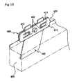
- FIGS. 16A and 16B are perspective views of a bracket 300 for securing a side airbag for an automotive vehicle according to a seventh exemplary embodiment of the present invention.
- the bracket 300 according to the seventh exemplary embodiment is similar to or same as the bracket 300 illustrated in FIGS. 14A and 14B, except for the shape of the fixing bracket aperture H. Therefore, the same reference numeral refers to the same element.
- both sides of a fixing bracket central aperture 310 which are opposite to each other lengthwise, are curved to bulge towards the center of the fixing bracket central aperture 310. That is, the width of the fixing bracket central aperture 310 becomes progressively narrower toward the middle part thereof.
- connection strap 52 connected to the side airbag is prevented from being folded or inclined downward. Therefore, a passenger is protected by installing the bracket 300 which enables the side airbag to be properly operated upon a side crash of the vehicle.
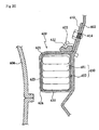
- FIGS. 17, 18A, 188 and 19 An eighth exemplary embodiment of the present invention will be described with reference to FIGS. 17, 18A, 188 and 19.
- FIG. 17 is a front view of an installation position of a bracket 400 for securing a side airbag 401 for an automotive vehicle according to the eighth exemplary embodiment of the present invention.
- a front part of the side airbag 401 which is installed inside a roof side panel 402 is secured to a front pillar 405, and a rear part of the side airbag 401 with an inflator 404 is connected to a rear pillar 406.
- the side airbag 401 includes a sensor and an electronic control unit.
- the sensor senses a crash of the vehicle, and the electronic control unit operates the inflator 404 by receiving a signal form the sensor.
- FIGS. 18A and 18B show the bracket according to the eighth exemplary embodiment.
- the bracket 400 comprises a lower plate 420, an upper plate 410 and an extension plate 440.
- the lower plate has connection hooks 422.
- the upper plate 410 is horizontally connected to one side of the lower plate 420 by a joint strap 430.
- the extension plate 440 is extended from the lower plate 420 downwardly.
- the bracket 400 restrains a side airbag 401 as the upper plate 410 is connected to the lower plate 420.
- the lower plate 420 comprises a lower plate installation aperture 421 for fastening a bolt to the roof side panel 402; hooking protrusions 424 for assisting the securing of the bracket 400 to the roof side panel 402 and for restraining rotation of the bracket 400; and connection hooks 422 formed at the right and left of the lower plate installation aperture 421 and secured to the upper plate 410.
- Each hooking protrusion 424 is connected to any one side of the square-shape aperture formed in the lower plate 420 and is formed by bending the back surface of the lower plate 420 which is secured to the roof side panel 402, as illustrated in FIG 18B.
- the bracket 400 Before the bracket 400 is fastened to the roof side panel 402 by the bolt, the bracket 400 is held by a hook groove (not shown) formed on the roof side panel 402. Therefore, working becomes easy because there is no trouble of holding the bracket 400 when it is fastened by the bolt.
- bracket 400 is prevented from turning by a rotation force generated when the bracket 400 is fastened by the bolt.
- connection hooks 422 for connection to the upper plate 410 are formed to vertically protrude from the other surface of the lower plate 420 on which two hook apertures 423 are formed. Further, since the end parts of the connection hooks 422 are bent to face each other, when connecting to the upper plate 410, the connection hooks 422 restrain the upper plate 410 so as not to be easily deviated.
- connection hooks 422 make it easy for the connection hooks 422 to move, so that the connection hooks 422 are prevented from being easily broken when connecting to or separating from the upper plate 410.
- the upper plate 410 is connected to be level to the lower plate 420 by the joint strap 430 formed at one side thereof.
- An upper plate installation aperture 411 is formed on the upper plate 410, to correspond to the lower plate installation aperture 421.
- Insertion apertures 412 are formed on the upper plate 410, at the positions corresponding to the connection hooks 422 of the lower plate 420, so that the connection hooks 422 are inserted into the insertion apertures 412
- Spacing apertures 414 are formed at both ends of each of the insertion apertures 412.
- a movable plate 413 is included between the spacing apertures 414. One end of the movable plate 413 is connected to the upper plate 410, so that the connection hooks 422 and the insertion apertures 412 are prevented from being damaged when they are connected to or separated from each other.
- the extension plate 440 is extended from a lower end part of the lower plate 420 and is bent at an obtuse angle towards the roof side panel 402. Therefore, the bracket 400 is increasingly secured to a body of the vehicle and the direction of deploying the side airbag cushion 409 is guided when the side airbag is operated.
- a reinforcement protrusion 450 is integrally formed, at a predetermined height, around the lower plate installation aperture 421 at one side of the lower plate 420.
- the reinforcement protrusion 450 functions as a washer which prevents the bracket 400 from being seriously damaged by strong torque when the bracket 400 is fastened by the bolt and prevents both ends of the bracket 400 from being spaced when the bolt is unnecessarily deeply screwed.
- Another reinforcement protrusion 450 is formed around the upper plate installation aperture 411. Therefore, when the upper plate 410 is assembled with the lower plate 420, securing of the end of the side airbag 401 is improved.
- the one end of the side airbag 401 is fabricated to integrally protrude is inserted into the connection hooks 422 of the lower plate 420.
- the upper plate 410 connected by the joint strap 430 is covered over the lower plate 420.
- the connection hooks 422 of the lower plate 420 are inserted into the insertion apertures 412 formed on the upper plate 410.
- connection hooks 422 are more easily connected to the insertion apertures 412 by the motion of the movable plate 413. Upon wrong assembly, it is possible to artificially dissemble the bracket 400.
- the upper plate installation aperture 411 and the lower plate installation aperture 42 are formed at the corresponding positions, they are aligned to make it easy to fasten by the bolt.
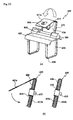
- FIGS. 20, 21A and 21B A ninth exemplary embodiment of the present invention will be described with reference to FIGS. 20, 21A and 21B.
- a front part of a side airbag housing which is installed inside a roof side panel is secured in a front pillar and a rear part thereof including an inflator is secured in a rear pillar.
- one or more holders are installed to cover the side airbag housing inside the roof side panel and the holders secure the side airbag housing to a body of an automotive vehicle.
- a side airbag module includes a sensor (not shown) sensing a crash of the vehicle, and an electronic control unit (not shown) operating the inflator by receiving a signal transmitted from the sensor.
- FIG. 20 is a sectional view illustrating an installation structure of a bracket 600 for securing a side airbag for an automotive vehicle according to the ninth exemplary embodiment.
- the bracket 600 is positioned between a roof side panel 602 and a headliner 604 and is fastened to the roof side panel 602, through an installation aperture 614 formed in a bracket clip 610, by a bolt.
- a restraint member 623 of the bracket 600 is installed to cover a side airbag housing 650.
- a cut part 624 is positioned nearby a headliner 604, to be easily parted and deployed inside the vehicle when a side airbag cushion 651 is deployed.
- FIGS. 21A and 21 B show a shape of the bracket 600 according to the ninth exemplary embodiment.
- a body of the bracket 600 is made of plastics and comprises a restraint plate 621, a connection part 626, and a restraint member 623.
- the restraint plate 621 restrains an upper part of the side airbag housing 652.
- the connection part 626 is formed on one side of the restraint plate 621.
- the restraint member 623 covers the side airbag.
- Securing hooks 622 to be connected to a hook connection part 625 are formed at both sides of the connection part 626 and extended toward the restraint plate 621.
- the restraint plate 621 restrains the upper part of the side airbag housing 652.
- the connection part 626 is connected to the restraint plate 621 and is formed at an obtuse angle at one side of the restraint plate 621.
- the bracket clip 610 illustrated in FIG. 21 B is fitted with the connection part 626, to be secured to the body of the vehicle.
- one or more restraint members 623 respectively including the cut parts 624 are connected to the other side of the restraint plate 621.
- the hook connection part 625 to be connected to the securing hooks 622 is formed at the end of each restraint member 623.
- the cut part 624 positioned in the middle part of each restraint plate 623 is cut at a predetermined part, to be easily parted when the side airbag housing 652 is deployed.
- the bracket clip 610 is a metal piece made of an iron material.
- two support plates 611 a and 611b are formed based on a bending part 612.
- the thickness of the bending part 612 of the bracket clip 610 is same as or a little thicker than the thickness of the connection part 626, to cover the connection part 626.
- the width of the bracket clip 610 is same as or a little narrower than the protruded connection part 626.
- a ring-shaped rise 615 is formed on an outer circumference of the installation aperture 614 on the inner surface of any one of the two support plates 611a and 611b.
- the ring-shaped rise 615 passes through the aperture 614 of the connection part 626 and is inserted into the other support plate 611 a or 611 b.
- Each of the apertures in the support plate 611a, the connection part 626 and the support plate 611b is formed at the same position, to make it easy to fasten the bolt.
- Hooking protrusions 613 are respectively formed at both side ends of the support plate 611a or 611b which is secured to the roof side panel 602.
- the hooking protrusions 613 are hooked in hook grooves (not shown) formed on the roof side panel 602 before the bolt is screwed.
- bracket 600 since an operator does not need to hold the bracket 600 by hand or any additional tool before the bracket 600 is fastened to the body of the vehicle by the bolt, the installation is simple and the working time is shortened. Further, since the bracket clip 610 is prevented from turning by the rotation force generated when the bolt is screwed, the installation work is easier.
- bracket is made of the iron material, a fastened part is not seriously damaged in spite of the excessive rotation force and fastening when the bolt is screwed.
- a bracket clip 610 with folded support plates 611 a and 611b covers a connection part 626, thereby allowing a ring-shaped rise 615 formed on any one support plate 611a or 611b to be inserted into an installation aperture 614 of the connection part 626 and subsequently to be inserted into the other support plate 611 a or 611 b while hooking protrusions 613 of the bracket clip 610 are hooked in hook grooves (not shown) of a roof side panel 602.
- FIG. 228 shows a section view of the installed bracket clip 610.
- the ring-shaped rise 615 formed in the inner side of the support plate 611b of the bracket clip 610 is inserted into the connection part 626 from the back side of the connection part 626. Subsequently, the ring-shaped rise 615 protruding from the connection part 626 is inserted into the installation aperture 614, which is formed on the other support plate 611a which is bent over the upper part of the connection part 626. Therefore, a body 620 is secured by the bracket clip 610.
- FIGS. 23A and 23B show mounting of the bracket 600 according to the tenth exemplary embodiment.
- restraint members 623 are respectively firstly bent at cut parts 624.
- the restraint members are respectively secondarily bent at the parts which are same as a restraint plate 621 in width, to cover a side airbag housing 652.
- the secondarily bent restraint members 623 allow the hook connection part 625 to be hooked into the securing hooks 622 positioned at both side of the connection part 626.
- Both side ends of the hook connection part 625 are greater in size than the other parts hooked into the securing hooks 622, thereby restraining the bracket 600 from being shaken side to side, to be more stably secured.
- the bracket for securing a side airbag for an automotive vehicle when the bracket is fastened by a bolt, the bracket is prevented from being broken or deformed, by protecting the bolt fastened bracket formed on a mounting plate, and the side airbag is maintained in the best condition.
- the path of the connection strap connecting the side airbag to the bracket is fixed by the bracket and there is no interference by the connection strap when the bracket is assembled to install the side airbag in the A-pillar, thereby improving the assembling efficiency in the manufacturing site, to save time and improve productivity.
- connection strap is allowed to be easily released when the side airbag is deployed, it does not affect the deploying performance.
- bracket for securing a side airbag for an automotive vehicle since the connection strap connected to the bracket is prevented from turning, a failure is prevented while the side airbag is mounted. Further, even though the bracket is turned by the force generated when the mounted side airbag is operated upon an unexpected accident, since the fixing string is secured, it is prevented from being overlaid or inclined towards one side so that the side airbag is normally operated.
- the side airbag can be easily mounted in the manufacturing site, the working time is shortened and the productivity is improved.
- bracket for securing a side airbag for an automotive vehicle since the bracket is constituted in a single product to restrain the side airbag cushion, the working procedure in the working site is simplified and easy
- the bracket has the combination structure in which the upper plate and the lower plate are easily connected and separated, when it is erroneously assembled, it is easily separated without causing any damage to the product.
- bracket for securing a side airbag for an automotive vehicle since the side airbag housing is restrained without any additional components, the cost is reduced and working time is shortened in the manufacturing site.
- the side airbag cushion is smoothly deployed.
Landscapes
- Engineering & Computer Science (AREA)
- Mechanical Engineering (AREA)
- Air Bags (AREA)
Abstract
Description
- This application claims the benefit of
Korean Utility Model Application No. 2006-0006828, filed on Mar. 14, 2006 No. 2006-0007230, filed on Mar. 17, 2006 No. 2006-0008135 No. 2006-010369 No. 2006-010629 - The present invention relates to a bracket for securing a side airbag for an automotive vehicle and, more particularly, to a bracket for securing a side airbag for an automotive vehicle, which easily secures the side airbag and is prevented from being broken or deformed when it is fastened by a bolt.
- In addition to a safety belt, generally, an airbag module installed in an automotive vehicle is a device for maximally protecting an occupant against injury when the automotive vehicle crashes.
- An airbag module is typically installed in or around a steering wheel of a driver seat and in an instrument panel of a passenger seat. When an automotive vehicle crashes, the airbag module is operatively connected to a safety belt by a crash sensing sensor and an electronic control unit (hereinafter, referred to as "ECU"), and it maximally protects an occupant against injury.
- That is, when an automotive vehicle crashes, the crash sensing sensor outputs a crash sensing signal to the ECU. The ECU determines whether to operate an airbag, depending on the intensity of the crash. If the airbag needs to be operated, the ECU operates an inflator to inflate the airbag.
- In recent years, an airbag module has been installed at a side in an automotive vehicle, to protect an occupant upon a side impact crash
- The airbag module installed at the side of an automotive vehicle is generally called a 'side airbag.'
- The side airbag is installed in an A-pillar which is connected from the front passenger seat to the back seat. When side impact is applied, the side airbag is inflated by the operation of the inflator.
- In this application, a side airbag is used for an automotive vehicle, which prevents excessive inflation pressure from being applied to a lower end part of the side airbag to be deployed when the vehicle encounters a side crash, and balances the inflation pressure by an injected gas in a thorax bag and a head bag to reduce shaking when the side airbag is inflated and improves the work efficiency upon manufacture.
- The constitution of a side airbag will be described, in brief, with reference to FIG. 1A. The side airbag comprises: a
thorax bag 12 and ahead bag 11 to be deployed upon a side crash. Thethorax bag 12 comprises amounting part 14 and alower end part 16. Themounting part 14 has a neck shape at a rear side of thethorax bag 12. Thelower end part 16 is formed at a distance from themounting part 14. - An upper part and a lower part of the side airbag are formed symmetrically, based on the center of the
mounting part 14. Atether 13 is positioned between thethorax bag 12 and thehead bag 11. A vent aperture is formed in the side airbag at a distance from themounting part 14. Apulling plate 15 is symmetrical with thethorax bag 12, and thethorax bag 12 is extended from thehead bag 11. - The aforementioned side airbag is installed by fastening a bolt to the A-pillar of the automotive vehicle. To install the side airbag onto the A-pillar, additional securing devices are needed.
- That is, a number of brackets, each having a securing aperture into which a bolt is inserted, are positioned at predetermined positions of the side airbag and are secured by fastening bolts.
- An example of a conventional securing device of the aforementioned side airbag will be described with reference to FIG. 1B. A
bracket 3a with awelding bolt 2a is welded at one side of a back part frame 1 a. Aback part 7a with apad 5a covered by acover 6a is positioned at one side of aninstallation space 4a of the side airbag. - The end of the
cover 6a is inserted into theairbag installation space 4a. Therefore, one side of each of theairbag housing 8a and theairbag door 9a is positioned inside asupport wire 10a, and the other side of each of theairbag housing 8a and theairbag door 9a is fixed to thewelding bolt 2a of thebracket 3a. - However, since the conventional bracket for securing the side airbag is usually made of plastics, the bracket is broken or deformed while the bolt is fastened and therefore, the bracket cannot perform its function. Moreover, since this probiem makes it impossible for the side airbag to be normally operated, an occupant is fatally injured.
- Another
conventional side airbag 30 comprises: an airbag which is installed inside a headlining of a roof side panel; an inflator which is installed at one side of the airbag and which has a gas generating material to deploy the airbag upon a side crash; and a guide member with one side end which is connected to the airbag and the other side end which is positioned to pivot around the roof side panel. - The constitution of the
aforementioned side airbag 30 will be described, in detail, with reference to FIGS. 2A and 2B. - As described in FIG 2, a
headlining 21 is composed of plastics which are attached to the ceiling inside an automotive vehicle. Basic materials of theheadlining 21 are the surface and pad with the functions, such as insulation from the roof, insulation of sound, or absorption of sound inside the vehicle and the like. Theheadlining 21 is formed integrally with these surface and pad. - As a device to perform an operation of deploying the
side airbag 30, aninflator 40 rapidly burns a gas generating material including an element of sodium nitrite, and the like, by using an igniter and simultaneously generates nitrogen gas. Theinflator 40 is secured to aroof side panel 25 by aseparate bracket 41. - A strap 31 (hereinafter, referred to as "connection strap") is positioned at the other side of the
inflator 40. Thestrap 31 prevents one side of theside airbag 30 from waving when theairbag 30 is deployed by the inflator. This is illustrated in FIG. 2B. - However, since the conventional side airbag has no specific structure to hold the connection strap, it is troublesome to assemble the side airbag in the A-pillar due to the interference between the A-pillar and the connection strap.
- That is, an operator in a manufacturing site needs to check whether there is the interference with the connection strap when assembling the side airbag in the A-pillar. When the interference occurs, a process of avoiding the interference is added. As a result, a working time becomes longer and the assembling efficiency is deteriorated.
- Further, as illustrated in FIG. 3A, a
conventional bracket 50 for securing a side airbag has a shape in which aconnection strap 52 is connected to a simply longrectangular aperture 51. Therefore, thebracket 50 is not properly connected to theconnection strap 52. - That is, since the
connection strap 52 is movable in thebracket 50, theconnection strap 52 turns within therectangular aperture 51 of thebracket 50, as illustrated in FIG. 3B. - Therefore, when the side airbag is mounted in an automotive vehicle there are added a process of checking whether a state of the bracket is good or bad and, if the
connection strap 52 turns, a process of returning theconnection strap 52 to its original position. Consequently, the work becomes troublesome. - Moreover, the
bracket 50 is pulled towards the side airbag due to momentary gas explosive power which is generated while the side airbag is operated upon an accident. In this case, theconnection strap 52 inclines towards a lower part of therectangular aperture 51 as illustrated in FIG. 3C. Consequently, the side airbag is not stably secured. - Moreover, when a
connection strap 52 is cut by the friction caused during the accident, the side airbag is not inflated in a normal direction, upon the side crash. - Another
conventional side airbag 60 will be described with reference to FIGS. 4A and 4B. - As illustrated in FIGS. 4A and 4B, the
side airbag 60 comprises: aside airbag cushion 61, an inflator 62 supplying a gas to theside airbag cushion 61, a housing receiving the inflator 62, and adiffuser 64 included in theside airbag 60 and supplying a gas, which is generated from the inflator 62, to theside airbag cushion 61. - The inflator 62 is electrically connected to a control unit (not shown). The control unit is connected to a crash sensing sensor (not shown) in an automotive vehicle.
- The
side airbag cushion 61 is formed, at predetermined width and length, to sufficiently protect a head part of an occupant of the automotive vehicle. Atether 65 is provided in one part of an end of theside airbag cushion 61. Thetether 65 guides theside airbag 60 to be broadly inflated lengthwise or widthwise when theside airbag 60 is deployed. - The
diffuser 64 has a tube shape. A number of apertures (not shown) are formed, to be positioned lengthwise, on an outer circumference surface of thediffuser 64. While thediffuser 64 is received inside an upper end part of theside airbag 60, one end of thediffuser 64 is connected to thehousing 63 receiving theinflator 62. - When the
diffuser 64 and thehousing 63 are connected to each other, aholder 66 fastens a part of theside airbag 60 which covers the connection part of thediffuser 64 and thehousing 63, to be sealed. - A number of
holders 67 are connected to the upper end of theside airbag 60, at a predetermined interval. Theholders 67 secure theside airbag cushion 61 to a roof rail. Theholders 67 cover an external surface of aside airbag housing 68 and temporarily hold theside airbag housing 68. Theside airbag housing 68 covers theside airbag cushion 61 which is folded. - However, in the
conventional side airbag 60, theholders 67 securing theside airbag 60 are formed of a single material. When theholders 67 are made of a soft material, an additional component is needed to prevent theholders 67 from being broken when theside airbag 60 is secured to the automotive vehicle by fastening a bolt. When the holders are made of a hard material to prevent the holders from being broken, there is a difficulty in cutting a cutting part when theside airbag 60 is deployed. - Further, in the aforementioned
conventional side airbag 60, a space of eachholder 67 is narrow and a shape of theholder 67 is gradually narrower downwardly. Therefore, since a region for supporting theside airbag 60 is narrow,many holders 67 are needed. This results in a longer working time in the manufacturing site. - That is, when the
conventional side airbag 60 is mounted, since the additional components are needed and a number ofholders 67 are installed, the assembling efficiency is lowered and the operability is not consistently provided by the defect of assembly. - Therefore, the present invention is directed to provide a bracket for securing a side airbag for an automotive vehicle, wherein, when the bracket is fastened by a bolt, the bracket is prevented from being broken or deformed, by protecting the bolt fastened bracket formed on a mounting plate, and wherein the side airbag is maintained in the best condition.
- Another object of the present invention is to provide a bracket for securing a side airbag for an automotive vehicle, wherein assembling the side airbag in a manufacturing site is easy, by fixing a path of a connection strap so that the connection strap connecting the side airbag to the bracket is secured against an A-pillar and by removing interference with the connection strap upon the assembling of the side airbag.
- Another object of the present invention is to provide a bracket for securing a side airbag for an automotive vehicle, wherein a connection strap is prevented from affecting a deploying performance of the side airbag, by making it easy for the connection strap to be released from a clip.
- Another object of the present invention is to provide a bracket for securing a side airbag for an automotive vehicle, wherein an operator easily mounts the side airbag in a manufacturing site by preventing a connection strap from turning in an aperture of the bracket used for securing the side airbag, and wherein a failure in a securing structure is prevented.
- Another object of the present invention is to provide a bracket for securing a side airbag for an automotive vehicle, wherein safety of a passenger is improved by normally absorbing side impact applied to the passenger upon an accident, by preventing a connection strip from being inclined towards one side when a bracket of the side airbag is distorted upon a crash, and by enabling a normal operation of the side airbag.
- Another object of the present invention is to provide a bracket for securing a side airbag for an automotive vehicle, wherein an airbag cushion is restrained by one component.
- Another object of the present invention is to provide a bracket for securing a side airbag for an automotive vehicle, wherein the side airbag is simply assembled to be easily secured and the side airbag is easily dissembled without breakage, so that the efficiency in assembling or dissembling the side airbag is improved.
- Another object of the present invention is to provide a bracket for securing a side airbag for an automotive vehicle, wherein the side airbag is stably secured without using any additional components.
- Another object of the present invention is to provide a bracket for securing a side airbag for an automotive vehicle, wherein a cut part is easily parted when the side airbag is deployed, so that the airbag cushion is smoothly deployed.
- Exemplary embodiments of the present invention provide brackets for securing a side airbag for an automotive vehicle.
- In accordance with an exemplary embodiment, a bracket for securing a side airbag for an automotive vehicle, comprises: a mounting plate for securing the side airbag to the vehicle, including a body and a connection part formed on the body; and a bracket clip installed on the external surface of the connection part, and wherein the connection part has a through aperture through which a bolt is fastened and protrusions are each formed on each of both side ends of the connection part, and the bracket clip comprises: a bending part formed in the middle of the bracket clip; a plurality of support plates formed at both side of the bending part; and through apertures formed on the support plates, corresponding to the through aperture of the connection part.
- In accordance with another exemplary embodiment, a bracket for securing a side airbag for an automotive vehicle, comprises: a bracket for fixing a connection strap which is configured to connect the side airbag to the vehicle, and wherein the bracket comprises: a support plate; an installation plate positioned at a middle upper part of the support plate and including an installation aperture; and a fixing part formed by being forwardly bent from the right and left edges, with respect to the installation plate, of the support plate.
- In accordance with another exemplary embodiment, a bracket for securing a side airbag for an automotive vehicle, which connects a connection strap, connected to the side airbag, to a pillar of the vehicle, comprises: an installation aperture to be secured to the pillar; and a fixing bracket aperture through which the connection strap connected to the side airbag passes, and wherein the fixing bracket aperture comprises: a fixing bracket central aperture through which the connection strap passes; and extension apertures formed at both ends of the fixing bracket central aperture and each having a greater width than that of the fixing bracket central aperture.
- In accordance with another exemplary embodiment, a bracket for securing a side airbag for an automotive vehicle, which is installed inside a roof side panel, comprises: a lower plate having a lower plate installation aperture and connection hooks each formed at the right and left of the lower plate installation aperture; an upper plate connected to one side of the lower plate and having an upper plate installation aperture and insertion apertures formed at the right and left of the upper plate installation aperture, each insertion aperture to which each connection hook is connected; and an extension plate extended downward the lower plate.
- In accordance with another exemplary embodiment, a bracket for securing a side airbag to an automotive vehicle, comprises: a bracket clip made of a metal piece being bent, the bracket clip including a bending part, two support plates formed at either side of the bending part, and installation apertures respectively formed in the support plates; a body of the bracket; and, wherein the body of the bracket comprises: a restraint plate restraining a side airbag housing; a number of restraint members which are extended downwardly from at one side of the restraint plate and cover a side airbag housing, and a hook connection part which is extended and form at ends of the restraint members; and a connection part which is bent to be formed at the other side of the restraint panel and into which the bracket clip is inserted.
- The above and other features and advantages of the present invention will become more apparent to those of ordinary skill in the art by describing in detail preferred embodiments thereof with reference to the attached drawings in which:
- FIG. 1A shows an example of a conventional side airbag;
- FIG. 1 B shows an example of a conventional bracket for securing a side airbag;
- FIGS. 2A and 2B show an example of another conventional side airbag;
- FIGS. 3A, 3B and 3C are front views of another conventional securing bracket;
- FIGS. 4A and 4B respectively show another conventional side airbag which is assembled and dissembled;
- FIG. 5 shows a state of carrying out a bracket for securing a side airbag for an automotive vehicle according to a first exemplary embodiment of the present invention;
- FIG. 6 is a perspective view of a bracket clip in the bracket according to the first exemplary embodiment;
- FIGS. 7A and 7B show examples of the bracket according to the first exemplary embodiment;
- FIG. 8 is a front view of an installation position of a bracket for securing a side airbag for an automotive vehicle according to a second exemplary embodiment of the present invention;
- FIG 9 is a perspective view of a shape of the bracket according to the second exemplary embodiment;
- FIGS. 10A and 10B are respectively a front view and a side view of the bracket of FIG. 9;
- FIG. 11 is a perspective view of the constitution connecting the bracket of FIG. 9 to a connection strap;
- FIG. 12 is a perspective view of a bracket for securing a side airbag for an automotive vehicle according to a third exemplary embodiment of the present invention;
- FIG. 13 is a perspective view of a bracket for securing a side airbag for an automotive vehicle according to a fourth exemplary embodiment of the present invention;
- FIGS. 14A and 14B are perspective views of a bracket for securing a side airbag for an automotive vehicle according to a fifth exemplary embodiment of the present invention;
- FIGS. 15A and 15B are perspective views of a bracket for securing a side airbag for an automotive vehicle according to a sixth exemplary embodiment of the present invention;
- FIGS. 16A and 16B are perspective views of a bracket for securing a side airbag for an automotive vehicle according to a seventh exemplary embodiment of the present invention;
- FIG. 17 is a front view of an installation position of a bracket for securing a side airbag for an automotive vehicle according to an eighth exemplary embodiment of the present invention;
- FIGS. 18A and 18B show an open state of the bracket according to the eighth exemplary embodiment;
- FIG. 19 shows a use example of the bracket according to the eighth exemplary embodiment;
- FIG. 20 is an installation sectional view of a bracket for securing a side airbag for an automotive vehicle according to a ninth exemplary embodiment of the present invention;
- FIGS. 21A and 21B show the bracket according to the ninth exemplary embodiment;
- FIGS. 22A and 22B show a bracket for securing a side airbag for an automotive vehicle according to a ninth exemplary embodiment of the present invention; and
- FIGS. 23A and 23B show the bracket according to the ninth exemplary embodiment.
- The present invention will now be described more fully hereinafter with reference to the accompanying drawings, in which preferred embodiments of the invention are shown. This invention may, however, be embodied in different forms and should not be construed as limited to the embodiments set forth herein.
- A
bracket 100 for securing a side airbag for an automotive vehicle according to a first exemplary embodiment will be described, in detail, with reference to the accompanying drawings. - FIG. 5 shows a state of carrying out a bracket for securing a side airbag for an automotive vehicle according to a first exemplary embodiment of the present invention; FIG 6 is a perspective view of a bracket clip in the device according to the first exemplary embodiment; and FIGS. 7A and 7B show examples of the bracket according to the first exemplary embodiment.
- As illustrated in FiGS. 5, 6, 7A and 7B, a mounting
plate 130 is a device for supporting aside airbag 101. The mountingplate 130 is installed to be secured to an upper frame (hereinafter, referred to as "A-pillar 110") of lateral windows by a bolt. - That is, the mounting
plate 130 is manufactured by injection molding of plastics in a rectangular form. Abent connection part 132 is integrally formed with one side of arectangular body 131, by injection molding. - A through aperture (135) through which a bolt(not shown) is fastened is formed in the center of the
connection part 132.Predetermined protrusions 133 are respectively formed on an external surface of one side of theconnection part 132, by protruding both side ends of theconnection part 132 at a predetermined height. - A
bracket clip 120 is a nearly rectangular metal plate as illustrated in FIG. 6. A bendingpart 121 is formed in the middle of thebracket clip 120. A plurality ofsupport plates part 121. - An
aperture 124 is formed in each of thesupport plates aperture 124 is aligned with the through aperture (not shown) of theconnection part 132. - A predetermined ring-shaped
rise 123 may be formed on an outer circumference of theaperture 124 which is formed on an inner surface of any one (for example, thesupport plate 122b) among thesupport plates rise 123 is inserted into the through aperture (not shown) of theconnection part 132. - Further, since the
bracket clip 120 is to be held between theprotrusions 133 formed in theconnection part 132, the width of thebracket clip 120 is same as or less than the distance between theprotrusions 133. - Assembling process of the bracket according to the first embodiment of the present invention will be described with reference to FIGS. 5, 6, 7A and 78.
- As illustrated in FIG. 7A, the
bracket clip 120 is positioned at an external surface of theconnection part 132. Thebracket clip 120 is attached to theconnection part 132 by inserting the ring-shapedrise 123 formed on onesupport plate 122b into the through aperture of theconnection part 132 and by folding theother support plate 122a, so that thesupport plates connection part 132. - As illustrated in FIG. 7B, assembling of the
bracket 100 for securing a side airbag for an automotive vehicle according to the first exemplary embodiment of the present invention is completed. - The
bracket 100 for securing a side airbag for an automotive vehicle, which is completely assembled in the above-described manner, is installed to be fixed onto the A-pillar 110 of a body of vehicle. - That is, after the
connection part 132 connected to thebracket clip 120 is positioned at an appropriate position of the A-pillar 110, thebracket 100 for securing a side airbag for an automotive vehicle is secured by fastening the bolts (not shown) which is inserted into theaperture 124 formed on thesupport plates bracket clip 120 and into the through-hole (not shown) of theconnection part 132. - Then, even the bolt is too tightly fastened, since the
bracket clip 120 formed of a metal material protects theconnection part 132, theconnection part 132 is prevented from being broken or deformed. - The
side airbag 101 is secured against the lower surface of thebody 131 of the mountingplate 130. - A
bracket 200 for securing a side airbag for an automotive vehicle according to a second exemplary embodiment will be described, in detail, with reference to the accompanying drawings. - The same reference numeral refers to the same element, and no further description of the same element will be presented.
- FIG. 8 is a front view of an installation position of the
bracket 200 for securing a side airbag for an automotive vehicle according to the second exemplary embodiment of the present invention. - As illustrated in FIG. 8, a
side airbag 201 is mounted inside a roof side panel R of the vehicle. One end of theside airbag 201 is secured to abuckle 205 in an A-pillar 202, and the other end thereof is connected to a C-pillar P through an inflator 206. - The
side airbag 201 and thebuckle 205 are connected to each other by aconnection strap 204. Thebracket 200 fixing a path of theconnection strap 204 is positioned in the middle part of theconnection strap 204. - The
side airbag 201 includes a sensor (not shown) for sensing a crash of the vehicle and an electronic control unit for operating the inflator 206 by receiving a signal from the sensor. - That is, the
buckle 205 is fixed to the A-pillar 202 at the front part of theside airbag 201. Thebuckle 205 is connected to theside airbag 201 by theconnection strap 204. Theconnection strap 204 is fixed by thebracket 200. - The inflator 206 including a gas for deploying the
side airbag 201 is installed in the rear part of the side airbag. - FIGS. 9 through 11 are perspective views of a shape of the
bracket 200 according to the second embodiment. - As illustrated, the
bracket 200 comprises asupport plate 210 and aninstallation plate 230. Theinstallation plate 230 is formed by being bent from thesupport plate 210. - An
installation aperture 231 is formed in theinstallation plate 230. When theside airbag 201 is installed in the vehicle, a bolt is fastened through theinstallation aperture 231. Ahook 232 is formed on an upper end of theinstallation plate 230. Thehook 232 makes it easy to be secured when theside airbag 201 is installed in the vehicle. - The
support plate 210 is a part of directly fixing theconnection strap 204. Fixingplates 220 are respectively formed to be bent at an upper end of both sides of thesupport plate 210. - Therefore, after the
side airbag 201 is mounted in the vehicle, the fixingplates 220 are pressed so that theconnection strap 204 is positioned between the fixingplates 220 and thesupport plate 210. Accordingly, the fixingplates 220, theconnection strap 204 and thesupport plate 210 are secured to one another. - Two pairs of fixing
protrusions 221 formed on the fixingplates 220 enable theconnection strap 204 to be more stably fixed. - Further, a slimming
aperture 212 in a rectangular form is made in the middle of thesupport plate 210, for cost reduction and weight reduction. Two pairs ofapertures 211 are formed on both sides of the slimmingaperture 212. Theapertures 211 are positioned so as to correspond to the fixingprotrusions 221 of the fixingplates 210, so that the fixingprotrusions 221 are respectively inserted into theapertures 211. - FIG. 10 is a perspective view of a shape of the
bracket 200 and theconnection strap 204 according to the second exemplary embodiment. - As illustrated in FIG. 10, the fixing
plates 220 of thebracket 200 are pressed to be fixed when the fixingplates 220 are assembled with theconnection strap 204. Further, the fixingprotrusions 221 to be inserted into theapertures 211 of thesupport plate 210 press theconnection strap 204 to be fixed, without interference. Therefore, the security between theconnection strap 204 and the fixingplates 220 is increased. - FIG. 11A is a front view of the
bracket 200 and FIG. 11B is a side view of thebracket 200 according to the second exemplary embodiment. - As illustrated in FIGS. 11A and 11B, since the fixing
plates 220 are bent to form an obtuse angle between the fixingplates 220 and thesupport plate 210, a bolt is easily fastened and thebracket 200 is secured to a body of the vehicle. - Further, the fixing
plates 220 are bent towards thesupport plate 210 so that the pressing process is easy upon the assembling. The ends of the fixingplates 220 are slightly bent to hold theconnection strap 204 downwardly when the fixingplates 220 are pressed to fix theconnection strap 204. The slightly bending ends of the fixingplates 220 are one-touch connected to the downward edge of thesupport plate 210, thereby preventing theconnection strap 204 from slipping out from thebracket 200. - Further, the description of the same constitution of third and fourth exemplary embodiments of the present invention as that of the second exemplary embodiments described above will not be further presented. The different constitution of the third and fourth exemplary embodiments from the second exemplary embodiment will be described in brief.
- FIG. 12 is a perspective view of a
bracket 200 for securing a side airbag for an automotive vehicle according to the third exemplary embodiment. - As illustrated in FIG. 12, one of fixing
plates 220 in thebracket 200 is bent from an upper end edge of asupport plate 210 and the other is bent from a lower end edge of thesupport plate 210, so that aconnection strap 204 is prevented from slipping down. - FIG. 13 is a perspective view of a
bracket 200 for securing a side airbag for an automotive vehicle according to the fourth exemplary embodiment. - As illustrated in FIG 13, fixing
protrusions 221 of fixingplates 220 in thebracket 200 respectively have a square form. Specifically, the fixingplates 220 are cut in the other three sides, except for a lower end, at predetermined positions. The cut three sides in each position are bent to protrude towards thesupport plate 210, thereby preventing aconnection strap 204 from slipping out. And holes 211 are formed to connect the fixingprotrusions 221 in thesupport plate 210. - In accordance with the above-described present invention, the
connection strap 204 which is formed to be extended to aside airbag 201 is fixed by thebracket 200 and the path of theconnection strap 204 is fixed. Therefore, there is no interference between theconnection strap 204 and the A-pillar when theside airbag 201 is assembled. Consequently, the efficiency of assembling in a manufacturing site is improved. Furthermore, since theconnection strap 204 is easily lift when theside airbag 201 is deployed, it does not affect the deploying performance. - A fifth embodiment of the present invention will be described with reference to FIG. 14 below.
- FIGS. 14A and 14B are perspective views of a
bracket 300 for securing a side airbag for an automotive vehicle and aconnection strap 52 connected to thebracket 300. - An
installation aperture 330 and a fixing bracket aperture H are formed inside thebracket 300. Theinstallation aperture 330 is to be secured to a pillar. Theconnection strap 52 connected to the side airbag passes through the fixing bracket aperture H. The fixing bracket aperture H includes a fixing bracketcentral aperture 310 andextension apertures 320 formed at both ends of the fixing bracket aperture H, to prevent the connection strap from turning. The width of theextension aperture 320 is greater than the width of the fixing bracketcentral aperture 310. - As illustrated in FIG. 14A, the
bracket 300 comprises theinstallation aperture 330, ahook 350, the fixing bracket aperture H and a bending processedpart 340. Theinstallation aperture 330 secures thebracket 300 to a body of the vehicle by fastening a bolt to a frame of the vehicle. Thehook 350 is of help in fixing the body of the vehicle. The fixing bracket aperture H is connected to theconnection strap 52. The bending processedpart 340 is formed between a part where theinstallation aperture 330 is formed and a part where the fixing bracket aperture H is formed. The bending processedpart 340 is formed at angles and results in a step to be easily installed. - Further the fixing bracket
central aperture 310 is a long aperture in a rectangular form. The extension apertures 320 are formed at both ends of the long aperture. The width of theextension apertures 320 is greater than the width of the long aperture, i.e., the fixing bracketcentral aperture 310. The connection parts between theextension apertures 320 and the fixing bracketcentral aperture 310 form a slope surface. - The two edges which are formed between the fixing bracket
central aperture 310 and theextension apertures 320 restrains the movement of theconnection strap 52, so that thebracket 300 does not turn before the side airbag is mounted in the vehicle. As a result, a failure is prevented. - When the side airbag is operated upon an unexpected accident during driving and even though the
bracket 300 secured to the body of the vehicle by abolt 380 is pulled towards the side airbag by the momentary explosive power of gas as shown in FIG. 14B, theconnection strap 52 is maintained in the shape in which theconnection strap 52 is first inserted into the fixing bracket aperture H. Theconnection strap 52 is not inclined toward one side or it is not cut. - When the side airbag is mounted in the vehicle in the manufacturing site, working is easy because there is no trouble of checking whether the condition of the bracket is good or bad and, if the bracket is turned, returning the bracket to its original position.
- FIGS. 15A and 15B are perspective views of a
bracket 300 for securing a side airbag for an automotive vehicle according to a sixth exemplary embodiment of the present invention. - The
bracket 300 according to the sixth exemplary embodiment is similar to or same as thebracket 300 illustrated in FIGS. 14A and 14B, except for the shape of the fixing bracket aperture H. Therefore, the same reference numeral refers to the same element. - Four hooking
protrusions 360 are formed around the connection parts where a fixing bracketcentral aperture 310 is connected toextension apertures 320 having the greater width than that of the fixing bracketcentral aperture 310. When aconnection strap 52 moves, theconnection strap 52 is held by the hookingprotrusions 360, thereby preventing theconnection strap 52 from being folded upward or downward and from being reversely turned. Therefore, theconnection strap 52 is firmly fixed to thebracket 300. - FIGS. 16A and 16B are perspective views of a
bracket 300 for securing a side airbag for an automotive vehicle according to a seventh exemplary embodiment of the present invention. - The
bracket 300 according to the seventh exemplary embodiment is similar to or same as thebracket 300 illustrated in FIGS. 14A and 14B, except for the shape of the fixing bracket aperture H. Therefore, the same reference numeral refers to the same element. - In the seventh exemplary embodiment, both sides of a fixing bracket
central aperture 310, which are opposite to each other lengthwise, are curved to bulge towards the center of the fixing bracketcentral aperture 310. That is, the width of the fixing bracketcentral aperture 310 becomes progressively narrower toward the middle part thereof. - In accordance with the above-described present invention, the
connection strap 52 connected to the side airbag is prevented from being folded or inclined downward. Therefore, a passenger is protected by installing thebracket 300 which enables the side airbag to be properly operated upon a side crash of the vehicle. - An eighth exemplary embodiment of the present invention will be described with reference to FIGS. 17, 18A, 188 and 19.
- FIG. 17 is a front view of an installation position of a
bracket 400 for securing aside airbag 401 for an automotive vehicle according to the eighth exemplary embodiment of the present invention. - As illustrated in FIG. 17, a front part of the
side airbag 401 which is installed inside aroof side panel 402 is secured to afront pillar 405, and a rear part of theside airbag 401 with aninflator 404 is connected to arear pillar 406. - At least one or
more brackets 400 are installed inside theroof side panel 402. Theside airbag 401 includes a sensor and an electronic control unit. The sensor senses a crash of the vehicle, and the electronic control unit operates the inflator 404 by receiving a signal form the sensor. - FIGS. 18A and 18B show the bracket according to the eighth exemplary embodiment.
- As illustrated in FIGS 18A and 18B, the
bracket 400 comprises alower plate 420, anupper plate 410 and anextension plate 440. The lower plate has connection hooks 422. Theupper plate 410 is horizontally connected to one side of thelower plate 420 by ajoint strap 430. Theextension plate 440 is extended from thelower plate 420 downwardly. Thebracket 400 restrains aside airbag 401 as theupper plate 410 is connected to thelower plate 420. - The
lower plate 420 comprises a lowerplate installation aperture 421 for fastening a bolt to theroof side panel 402; hookingprotrusions 424 for assisting the securing of thebracket 400 to theroof side panel 402 and for restraining rotation of thebracket 400; and connection hooks 422 formed at the right and left of the lowerplate installation aperture 421 and secured to theupper plate 410. - Each hooking
protrusion 424 is connected to any one side of the square-shape aperture formed in thelower plate 420 and is formed by bending the back surface of thelower plate 420 which is secured to theroof side panel 402, as illustrated in FIG 18B. - Before the
bracket 400 is fastened to theroof side panel 402 by the bolt, thebracket 400 is held by a hook groove (not shown) formed on theroof side panel 402. Therefore, working becomes easy because there is no trouble of holding thebracket 400 when it is fastened by the bolt. - Further, the
bracket 400 is prevented from turning by a rotation force generated when thebracket 400 is fastened by the bolt. - The connection hooks 422 for connection to the
upper plate 410 are formed to vertically protrude from the other surface of thelower plate 420 on which twohook apertures 423 are formed. Further, since the end parts of the connection hooks 422 are bent to face each other, when connecting to theupper plate 410, the connection hooks 422 restrain theupper plate 410 so as not to be easily deviated. - The
hook apertures 423 make it easy for the connection hooks 422 to move, so that the connection hooks 422 are prevented from being easily broken when connecting to or separating from theupper plate 410. - The
upper plate 410 is connected to be level to thelower plate 420 by thejoint strap 430 formed at one side thereof. An upperplate installation aperture 411 is formed on theupper plate 410, to correspond to the lowerplate installation aperture 421. -
Insertion apertures 412 are formed on theupper plate 410, at the positions corresponding to the connection hooks 422 of thelower plate 420, so that the connection hooks 422 are inserted into theinsertion apertures 412 - Spacing
apertures 414 are formed at both ends of each of theinsertion apertures 412. Amovable plate 413 is included between the spacingapertures 414. One end of themovable plate 413 is connected to theupper plate 410, so that the connection hooks 422 and theinsertion apertures 412 are prevented from being damaged when they are connected to or separated from each other. - The
extension plate 440 is extended from a lower end part of thelower plate 420 and is bent at an obtuse angle towards theroof side panel 402. Therefore, thebracket 400 is increasingly secured to a body of the vehicle and the direction of deploying theside airbag cushion 409 is guided when the side airbag is operated. - A
reinforcement protrusion 450 is integrally formed, at a predetermined height, around the lowerplate installation aperture 421 at one side of thelower plate 420. Thereinforcement protrusion 450 functions as a washer which prevents thebracket 400 from being seriously damaged by strong torque when thebracket 400 is fastened by the bolt and prevents both ends of thebracket 400 from being spaced when the bolt is unnecessarily deeply screwed. - Another
reinforcement protrusion 450 is formed around the upperplate installation aperture 411. Therefore, when theupper plate 410 is assembled with thelower plate 420, securing of the end of theside airbag 401 is improved. - A manufacturing structure of the bracket according to this embodiment will be described with reference to FIG. 19.
- The one end of the
side airbag 401 is fabricated to integrally protrude is inserted into the connection hooks 422 of thelower plate 420. Theupper plate 410 connected by thejoint strap 430 is covered over thelower plate 420. The connection hooks 422 of thelower plate 420 are inserted into theinsertion apertures 412 formed on theupper plate 410. - Then, the connection hooks 422 are more easily connected to the
insertion apertures 412 by the motion of themovable plate 413. Upon wrong assembly, it is possible to artificially dissemble thebracket 400. - Since the upper
plate installation aperture 411 and the lower plate installation aperture 42 are formed at the corresponding positions, they are aligned to make it easy to fasten by the bolt. - A ninth exemplary embodiment of the present invention will be described with reference to FIGS. 20, 21A and 21B.
- As illustrated, a front part of a side airbag housing which is installed inside a roof side panel is secured in a front pillar and a rear part thereof including an inflator is secured in a rear pillar.
- Then, one or more holders are installed to cover the side airbag housing inside the roof side panel and the holders secure the side airbag housing to a body of an automotive vehicle.
- A side airbag module includes a sensor (not shown) sensing a crash of the vehicle, and an electronic control unit (not shown) operating the inflator by receiving a signal transmitted from the sensor.
- FIG. 20 is a sectional view illustrating an installation structure of a
bracket 600 for securing a side airbag for an automotive vehicle according to the ninth exemplary embodiment. - As illustrated, the
bracket 600 is positioned between aroof side panel 602 and aheadliner 604 and is fastened to theroof side panel 602, through aninstallation aperture 614 formed in abracket clip 610, by a bolt. - A
restraint member 623 of thebracket 600 is installed to cover aside airbag housing 650. Acut part 624 is positioned nearby aheadliner 604, to be easily parted and deployed inside the vehicle when aside airbag cushion 651 is deployed. - FIGS. 21A and 21 B show a shape of the
bracket 600 according to the ninth exemplary embodiment. - As illustrated in FIG. 21A, a body of the
bracket 600 is made of plastics and comprises arestraint plate 621, aconnection part 626, and arestraint member 623. Therestraint plate 621 restrains an upper part of theside airbag housing 652. Theconnection part 626 is formed on one side of therestraint plate 621. Therestraint member 623 covers the side airbag. - Securing hooks 622 to be connected to a hook connection part 625 (to be described later) are formed at both sides of the
connection part 626 and extended toward therestraint plate 621. - The
restraint plate 621 restrains the upper part of theside airbag housing 652. Theconnection part 626 is connected to therestraint plate 621 and is formed at an obtuse angle at one side of therestraint plate 621. Thebracket clip 610 illustrated in FIG. 21 B is fitted with theconnection part 626, to be secured to the body of the vehicle. - Further, one or
more restraint members 623 respectively including thecut parts 624 are connected to the other side of therestraint plate 621. Thehook connection part 625 to be connected to the securing hooks 622 is formed at the end of eachrestraint member 623. - The
cut part 624 positioned in the middle part of eachrestraint plate 623 is cut at a predetermined part, to be easily parted when theside airbag housing 652 is deployed. - As illustrated in FIG 21B, the
bracket clip 610 is a metal piece made of an iron material. In thebracket clip 610, twosupport plates bending part 612. - The thickness of the bending
part 612 of thebracket clip 610 is same as or a little thicker than the thickness of theconnection part 626, to cover theconnection part 626. The width of thebracket clip 610 is same as or a little narrower than the protrudedconnection part 626. - A ring-shaped
rise 615 is formed on an outer circumference of theinstallation aperture 614 on the inner surface of any one of the twosupport plates rise 615 passes through theaperture 614 of theconnection part 626 and is inserted into theother support plate - Each of the apertures in the
support plate 611a, theconnection part 626 and thesupport plate 611b is formed at the same position, to make it easy to fasten the bolt. - Hooking
protrusions 613 are respectively formed at both side ends of thesupport plate roof side panel 602. The hookingprotrusions 613 are hooked in hook grooves (not shown) formed on theroof side panel 602 before the bolt is screwed. - Therefore, since an operator does not need to hold the
bracket 600 by hand or any additional tool before thebracket 600 is fastened to the body of the vehicle by the bolt, the installation is simple and the working time is shortened. Further, since thebracket clip 610 is prevented from turning by the rotation force generated when the bolt is screwed, the installation work is easier. - Further, since the bracket is made of the iron material, a fastened part is not seriously damaged in spite of the excessive rotation force and fastening when the bolt is screwed.
- As illustrated in FIG. 22A, a
bracket clip 610 with foldedsupport plates connection part 626, thereby allowing a ring-shapedrise 615 formed on any onesupport plate installation aperture 614 of theconnection part 626 and subsequently to be inserted into theother support plate protrusions 613 of thebracket clip 610 are hooked in hook grooves (not shown) of aroof side panel 602. - FIG. 228 shows a section view of the installed
bracket clip 610. As illustrated, the ring-shapedrise 615 formed in the inner side of thesupport plate 611b of thebracket clip 610 is inserted into theconnection part 626 from the back side of theconnection part 626. Subsequently, the ring-shapedrise 615 protruding from theconnection part 626 is inserted into theinstallation aperture 614, which is formed on theother support plate 611a which is bent over the upper part of theconnection part 626. Therefore, abody 620 is secured by thebracket clip 610. - FIGS. 23A and 23B show mounting of the
bracket 600 according to the tenth exemplary embodiment. - As illustrated in FIG. 23A,
restraint members 623 are respectively firstly bent atcut parts 624. As illustrated in FIG. 23B, the restraint members are respectively secondarily bent at the parts which are same as arestraint plate 621 in width, to cover aside airbag housing 652. - After turning a part of the
hook connection part 625 connected to therestraint members 623 from the back of thebracket clip 610 to the front of thebracket clip 610, the secondarilybent restraint members 623 allow thehook connection part 625 to be hooked into the securing hooks 622 positioned at both side of theconnection part 626. - Both side ends of the
hook connection part 625 are greater in size than the other parts hooked into the securing hooks 622, thereby restraining thebracket 600 from being shaken side to side, to be more stably secured. - In the bracket for securing a side airbag for an automotive vehicle according to the exemplary embodiment of the present invention, when the bracket is fastened by a bolt, the bracket is prevented from being broken or deformed, by protecting the bolt fastened bracket formed on a mounting plate, and the side airbag is maintained in the best condition.
- In the second to fourth exemplary embodiments of the present invention, the path of the connection strap connecting the side airbag to the bracket is fixed by the bracket and there is no interference by the connection strap when the bracket is assembled to install the side airbag in the A-pillar, thereby improving the assembling efficiency in the manufacturing site, to save time and improve productivity.
- In the bracket for securing a side airbag for an automotive vehicle according to the exemplary embodiments of the present invention, since the connection strap is allowed to be easily released when the side airbag is deployed, it does not affect the deploying performance.
- Consequently, waste due to unnecessary processes in the manufacturing site is eliminated, the assembling efficiency is improved, and upon an accident, the passenger is effectively protected because the deploying performance of the side airbag is not affected.
- In the bracket for securing a side airbag for an automotive vehicle according to each of the fifth to seventh exemplary embodiments of the present invention, since the connection strap connected to the bracket is prevented from turning, a failure is prevented while the side airbag is mounted. Further, even though the bracket is turned by the force generated when the mounted side airbag is operated upon an unexpected accident, since the fixing string is secured, it is prevented from being overlaid or inclined towards one side so that the side airbag is normally operated.
- Furthermore, since the side airbag can be easily mounted in the manufacturing site, the working time is shortened and the productivity is improved.
- In the bracket for securing a side airbag for an automotive vehicle according to the eighth exemplary embodiment of the present invention, since the bracket is constituted in a single product to restrain the side airbag cushion, the working procedure in the working site is simplified and easy
- Furthermore, since the bracket has the combination structure in which the upper plate and the lower plate are easily connected and separated, when it is erroneously assembled, it is easily separated without causing any damage to the product.
- In the bracket for securing a side airbag for an automotive vehicle according to each of the ninth exemplary embodiments of the present invention, since the side airbag housing is restrained without any additional components, the cost is reduced and working time is shortened in the manufacturing site.
- Further, since the materials having two different characteristics are used for the function of the bracket, there is no damage or performance failure in the materials. Furthermore, since the cut parts are easily parted, the side airbag cushion is smoothly deployed.
- The invention has been described using preferred exemplary embodiments. However, it is to be understood that the scope of the invention is not limited to the disclosed embodiments. On the contrary, the scope of the invention is intended to include various modifications and alternative arrangements within the capabilities of persons skilled in the art using presently known or future technologies and equivalents. The scope of the claims, therefore, should be accorded the broadest interpretation so as to encompass all such modifications and similar arrangements.
Claims (25)
- A bracket for securing a side airbag for an automotive vehicle, comprising:a mounting plate for securing the side airbag to the vehicle, including a body and a connection part formed on the body; anda bracket clip installed on the external surface of the connection part, andwherein the connection part has a through aperture through which a bolt is fastened and protrusions are each formed on each of both side ends of the connection part,
and the bracket clip comprises:a bending part formed in the middle of the bracket clip;a plurality of support plates formed at both side of the bending part; andthrough apertures formed on the support plates, corresponding to the through aperture of the connection part. - The bracket according to claim 1, wherein any one selected from the support plates comprises a ring-shape rise formed on an inner surface of the selected support plate, and the ring-shape rise is to be inserted into the through aperture of the connection part.
- The bracket according to claim 2, wherein the ring-shaped rise formed on the support plate is formed on the inside of the support plate around outer circumference of the through aperture.
- The bracket according to claim 3, wherein the bracket clip includes a protrusion which is bent on the surface connected with a body of the vehicle.
- A bracket for securing a side airbag for an automotive vehicle, comprising:a bracket for fixing a connection strap which is configured to connect the side airbag to pillar of the vehicle, andwherein the bracket comprises:a support plate;an installation plate positioned at upper part of the support plate and including an installation aperture; andfixing plates formed by being forwardly bent from the right and left edges, with respect to the installation plate, of the support plate.
- The bracket according to claim 5, wherein the fixing plates are bent from an upper end edge of the support plate.
- The bracket according to claim 5, wherein one of the fixing plates is bent from a upper end edge of the support plate, and the other one is bent from a lower end edge of the support plate.
- The bracket according to claim 5, wherein fixing protrusions and fixing apertures are complementarily formed on the support plate and the fixing plates, to be positioned to correspond to each other.
- The bracket according to claim 5, wherein the fixing plate is provided with fixing protrusion in a square shape with the other three sides are cut except for the lower end, to be bent towards the supporting plate.
- The bracket according to claim 5, wherein the end of the fixing plate is bent towards the supporting plate.
- The bracket according to claim 5, wherein a hook is formed on an upper end of the installation plate.
- A bracket for securing a side airbag for an automotive vehicle, comprising:a bracket which connects a connection strap, connected to the side airbag, to a pillar of the vehicle, andwherein the bracket comprises:an installation aperture to be secured to the pillar; anda fixing bracket aperture through which the connection strap connected to the side airbag passes, andwherein the fixing bracket aperture comprises:a fixing bracket central aperture through which the connection strap passes; andextension apertures formed at both ends of the fixing bracket central aperture and each having a greater width than that of the fixing bracket central aperture.
- The bracket according to claim 12, wherein connection parts where the fixing bracket central aperture is connected to the extension apertures respectively include a slope surface.
- The bracket according to claim 12, wherein hooking protrusions are formed in corners of the connection parts where the fixing bracket central aperture is connected to the extension apertures.
- The bracket according to claim 12, wherein curved parts formed to be bulged towards a center of the fixing bracket central aperture, so that the width between both sides of the fixing bracket central aperture becomes gradually narrower towards the center of the fixing bracket central aperture
- A bracket for securing a side airbag for an automotive vehicle which is installed inside a roof side panel, comprising:a lower plate having a lower plate installation aperture and connection hooks each formed at the right and left of the lower plate installation aperture;an upper plate connected to one side of the lower plate and having an upper plate installation aperture and insertion apertures formed at the right and left of the upper plate installation aperture, each insertion aperture to which each connection hook is connected; andan extension plate extended downward the lower plate.
- The bracket according to claim 16, wherein spacing apertures are formed, in a horizontal direction, on both ends of each insertion aperture of the upper plate and are parallel to each other, and a movable plate with its one end connected to the upper plate is formed between the spacing apertures.
- The bracket according to claim 16, wherein hooking protrusions are formed on the back surface of the lower plate, assisting in installation of the bracket onto the vehicle body.
- The bracket according to claim 16, wherein the extension plate is bent to form an obtuse angle to the roof side panel.
- The bracket according to claim 19, wherein reinforcement protrusions are respectively formed around the installation apertures formed in the upper plate and the lower plate.
- A bracket for securing a side airbag to an automotive vehicle, comprising:a bracket clip made of a metal piece being bent, the bracket clip including a bending part, two support plates formed at either side of the bending part, and installation apertures respectively formed in the support plates;a body of the bracket; and,wherein the body of the bracket comprises:a restraint plate restraining a side airbag housing;a number of restraint members which are extended downwardly from at one side of the restraint plate and cover a side airbag housing, and a hook connection part which is extended and formed at ends of the restraint members; anda connection part which is bent to be formed at the other side of the restraint plate and into which the bracket clip is inserted.
- The bracket according to claim 21, wherein the connection part has securing hooks formed at both sides of the connection part and extended toward the restraint plate, and the securing hooks are inserted by a hook connection part.
- The bracket according to claim 21, wherein each of the restraint members includes a cut part formed at a position corresponding to a corner of the side airbag housing.
- The bracket according to claim 21, wherein the bracket clip includes a protrusion which is bent on the surface connected with a body of the vehicle.
- The bracket according to claim 21, wherein any one of the support plates of the bracket clip includes a ring-shaped rise formed around the installation aperture formed in the support plate.
Applications Claiming Priority (5)
| Application Number | Priority Date | Filing Date | Title |
|---|---|---|---|
| KR2020060006828U KR200417596Y1 (en) | 2006-03-14 | 2006-03-14 | Fixing device for vehicle side airbag |
| KR2020060007230U KR200417621Y1 (en) | 2006-03-17 | 2006-03-17 | Buckle for car side air bag |
| KR2020060008135U KR200418224Y1 (en) | 2006-03-27 | 2006-03-27 | A clip for side airbag of vehicle |
| KR2020060010369U KR200420466Y1 (en) | 2006-04-18 | 2006-04-18 | Car Side Airbag Holder |
| KR2020060010629U KR200420483Y1 (en) | 2006-04-20 | 2006-04-20 | Bracket for Car Side Airbag |
Publications (1)
| Publication Number | Publication Date |
|---|---|
| EP1837252A1 true EP1837252A1 (en) | 2007-09-26 |
Family
ID=38110629
Family Applications (1)
| Application Number | Title | Priority Date | Filing Date |
|---|---|---|---|
| EP07005189A Withdrawn EP1837252A1 (en) | 2006-03-14 | 2007-03-13 | Bracket for securing side airbag for automotive vehicle |
Country Status (3)
| Country | Link |
|---|---|
| US (4) | US7523958B2 (en) |
| EP (1) | EP1837252A1 (en) |
| JP (4) | JP4559444B2 (en) |
Cited By (4)
| Publication number | Priority date | Publication date | Assignee | Title |
|---|---|---|---|---|
| WO2010099871A1 (en) * | 2009-03-06 | 2010-09-10 | Autoliv Development Ab | Attachment bracket and fastening device for fastening an airbag to a vehicle structure |
| WO2012053956A1 (en) * | 2010-10-22 | 2012-04-26 | Autoliv Development Ab | Bracket for fastening of a curtain airbag to a vehicle part |
| CN104908876A (en) * | 2015-06-24 | 2015-09-16 | 力帆实业(集团)股份有限公司 | Riding-type motorcycle ABS controller support |
| US9539978B2 (en) | 2011-11-30 | 2017-01-10 | Autoliv Development Ab | Curtain airbag for a vehicle |
Families Citing this family (62)
| Publication number | Priority date | Publication date | Assignee | Title |
|---|---|---|---|---|
| EP1857333A3 (en) * | 2006-05-19 | 2008-06-25 | Illinois Tool Works Inc. | Fastener for air-bag curtain |
| US7669883B2 (en) * | 2007-03-29 | 2010-03-02 | Newfrey Llc | Air bag bracket/fastener |
| JP4710862B2 (en) * | 2007-04-02 | 2011-06-29 | 豊田合成株式会社 | Air bag device for knee protection |
| WO2008139737A1 (en) * | 2007-05-14 | 2008-11-20 | Autoliv Development Ab | Curtain air bag device and method for manufacturing the same |
| JP5024956B2 (en) * | 2007-06-28 | 2012-09-12 | 日本プラスト株式会社 | Airbag fitting and airbag device |
| US8047560B2 (en) * | 2007-07-03 | 2011-11-01 | Avery Dennison Corporation | Retention cover for an inflatable object |
| JP5128229B2 (en) * | 2007-10-04 | 2013-01-23 | 本田技研工業株式会社 | Bracket for vehicle |
| DE102008033694A1 (en) * | 2008-07-17 | 2010-01-21 | Trw Automotive Gmbh | Airbag module with a gas bag, in particular a head-side gas bag |
| DE102008038925B4 (en) * | 2008-08-13 | 2015-09-24 | Autoliv Development Ab | Fastener and gas bag unit |
| US7887086B2 (en) * | 2008-09-12 | 2011-02-15 | Key Safety Systems, Inc. | Curtain air bag module and mounting clip |
| DE102008061282B4 (en) * | 2008-12-11 | 2021-03-04 | Autoliv Development Ab | Curtain airbag for a motor vehicle and fitting part for fastening a curtain airbag to a motor vehicle |
| DE102009022044A1 (en) * | 2009-05-18 | 2009-12-10 | Takata-Petri Ag | Fastening element for fastening airbag of arrangement of passenger-restraining system on vehicle structure, is provided with fixing device, over which fastening element is fixed in fastening opening of vehicle structure |
| DE102009022323A1 (en) * | 2009-05-22 | 2010-11-25 | Daimler Ag | Airbag attachment device with slider |
| US8047564B2 (en) * | 2009-09-02 | 2011-11-01 | Tk Holdings Inc. | Airbag |
| DE102010014051A1 (en) * | 2010-04-07 | 2011-10-13 | Gm Global Technology Operations Llc (N.D.Ges.D. Staates Delaware) | fastening device |
| US8628115B2 (en) * | 2010-10-05 | 2014-01-14 | GM Global Technology Operations LLC | Impact elements for a mounting system for a pressure vessel |
| WO2012121175A1 (en) * | 2011-03-04 | 2012-09-13 | オートリブ ディベロップメント エービー | Curtain airbag |
| US8602445B2 (en) | 2011-09-21 | 2013-12-10 | Chrysler Group Llc | Attachment clip |
| JP6035926B2 (en) * | 2012-07-11 | 2016-11-30 | 三菱自動車工業株式会社 | Fixed structure for on-board equipment |
| US9415713B2 (en) | 2013-01-24 | 2016-08-16 | Ford Global Technologies, Llc | Flexible seatback system |
| US9399418B2 (en) | 2013-01-24 | 2016-07-26 | Ford Global Technologies, Llc | Independent cushion extension and thigh support |
| US9409504B2 (en) | 2013-01-24 | 2016-08-09 | Ford Global Technologies, Llc | Flexible seatback system |
| JP6167578B2 (en) * | 2013-03-14 | 2017-07-26 | スズキ株式会社 | Curtain airbag storage structure |
| DE102013008467B4 (en) * | 2013-05-21 | 2017-03-23 | Trw Automotive Gmbh | Fastening device for a folded airbag |
| US9315131B2 (en) | 2014-01-23 | 2016-04-19 | Ford Global Technologies, Llc | Suspension seat back and cushion system having an inner suspension panel |
| US9421894B2 (en) | 2014-04-02 | 2016-08-23 | Ford Global Technologies, Llc | Vehicle seating assembly with manual independent thigh supports |
| US9789790B2 (en) | 2014-10-03 | 2017-10-17 | Ford Global Technologies, Llc | Tuned flexible support member and flexible suspension features for comfort carriers |
| US9566930B2 (en) | 2015-03-02 | 2017-02-14 | Ford Global Technologies, Llc | Vehicle seat assembly with side-impact airbag deployment mechanism |
| EP3480067B1 (en) * | 2015-03-05 | 2020-11-04 | Autoliv Development AB | Holding member of curtain airbag strap, curtain airbag device |
| CN106143389B (en) * | 2015-04-07 | 2020-10-27 | 福特环球技术公司 | Airbag connection and vehicle airbag system comprising said airbag connection |
| JP2018520936A (en) | 2015-07-07 | 2018-08-02 | トヨタ ボウショク アメリカ インコーポレーテッド | Misinstallation prevention bracket for installing airbag strip for seat trim cover on seat frame |
| US10046682B2 (en) | 2015-08-03 | 2018-08-14 | Ford Global Technologies, Llc | Back cushion module for a vehicle seating assembly |
| US9573550B1 (en) | 2015-08-17 | 2017-02-21 | Autoliv Asp, Inc. | Side curtain airbag compression inflator bracket |
| JP2017039477A (en) * | 2015-08-21 | 2017-02-23 | 本田技研工業株式会社 | Airbag mounting structure |
| US9981625B2 (en) * | 2016-02-25 | 2018-05-29 | Autoliv Asp, Inc. | Airbag mounting bracket |
| US10286818B2 (en) | 2016-03-16 | 2019-05-14 | Ford Global Technologies, Llc | Dual suspension seating assembly |
| US9849817B2 (en) | 2016-03-16 | 2017-12-26 | Ford Global Technologies, Llc | Composite seat structure |
| US9994135B2 (en) | 2016-03-30 | 2018-06-12 | Ford Global Technologies, Llc | Independent cushion thigh support |
| US10220737B2 (en) | 2016-04-01 | 2019-03-05 | Ford Global Technologies, Llc | Kinematic back panel |
| US9889773B2 (en) | 2016-04-04 | 2018-02-13 | Ford Global Technologies, Llc | Anthropomorphic upper seatback |
| US9802512B1 (en) | 2016-04-12 | 2017-10-31 | Ford Global Technologies, Llc | Torsion spring bushing |
| CN107310521A (en) * | 2016-04-26 | 2017-11-03 | 福特环球技术公司 | Connector and restraint assembly for vehicle |
| JP6615991B2 (en) * | 2016-06-03 | 2019-12-04 | オートリブ ディベロップメント エービー | Curtain airbag device |
| US9845029B1 (en) | 2016-06-06 | 2017-12-19 | Ford Global Technologies, Llc | Passive conformal seat with hybrid air/liquid cells |
| US9834166B1 (en) | 2016-06-07 | 2017-12-05 | Ford Global Technologies, Llc | Side airbag energy management system |
| US9849856B1 (en) | 2016-06-07 | 2017-12-26 | Ford Global Technologies, Llc | Side airbag energy management system |
| US10377279B2 (en) | 2016-06-09 | 2019-08-13 | Ford Global Technologies, Llc | Integrated decking arm support feature |
| US10166895B2 (en) | 2016-06-09 | 2019-01-01 | Ford Global Technologies, Llc | Seatback comfort carrier |
| US10286824B2 (en) | 2016-08-24 | 2019-05-14 | Ford Global Technologies, Llc | Spreader plate load distribution |
| US10279714B2 (en) | 2016-08-26 | 2019-05-07 | Ford Global Technologies, Llc | Seating assembly with climate control features |
| US10239431B2 (en) | 2016-09-02 | 2019-03-26 | Ford Global Technologies, Llc | Cross-tube attachment hook features for modular assembly and support |
| US10391910B2 (en) | 2016-09-02 | 2019-08-27 | Ford Global Technologies, Llc | Modular assembly cross-tube attachment tab designs and functions |
| JP6460070B2 (en) * | 2016-09-14 | 2019-01-30 | トヨタ自動車株式会社 | Curtain airbag device for vehicle |
| CN108068743A (en) * | 2016-11-09 | 2018-05-25 | 福特环球技术公司 | Curtain airbag for vehicle fixing device |
| US9914378B1 (en) | 2016-12-16 | 2018-03-13 | Ford Global Technologies, Llc | Decorative and functional upper seatback closeout assembly |
| US10596936B2 (en) | 2017-05-04 | 2020-03-24 | Ford Global Technologies, Llc | Self-retaining elastic strap for vent blower attachment to a back carrier |
| US10787144B1 (en) * | 2017-08-23 | 2020-09-29 | Fenton Mobility Products, Inc. | Headliner bar assembly for compliant airbags |
| CN112172732B (en) * | 2019-07-01 | 2023-07-14 | 奥托立夫开发公司 | Airbag module |
| KR102761183B1 (en) * | 2020-04-10 | 2025-01-31 | 현대모비스 주식회사 | Driver seat airbag |
| KR102343923B1 (en) * | 2020-09-28 | 2021-12-29 | 엔브이에이치코리아(주) | Module clip for insulator |
| US11433844B2 (en) | 2020-10-21 | 2022-09-06 | Ford Global Technologies, Llc | Bracket for a pillar assembly |
| US12017601B2 (en) * | 2022-11-10 | 2024-06-25 | ZF Passive Safety Systems US Inc. | Mounting bracket for curtain airbag |
Citations (5)
| Publication number | Priority date | Publication date | Assignee | Title |
|---|---|---|---|---|
| US20030042712A1 (en) | 2001-08-29 | 2003-03-06 | David Henderson | Mounting assembly for inflatable curtain |
| EP1359061A2 (en) | 2002-05-01 | 2003-11-05 | Trw Vehicle Safety Systems, Inc. | Modular headliner and inflatable curtain assembly |
| US20050029778A1 (en) | 2003-08-06 | 2005-02-10 | Robert Weber | Mounting bracket with fastener retention |
| EP1564083A2 (en) | 2004-02-16 | 2005-08-17 | Key Safety Systems, Inc. | Attachment of a curtain airbag assembly to a vehicle |
| KR100526149B1 (en) | 2003-06-11 | 2005-11-03 | 현대모비스 주식회사 | Curtain airbag system which is installed near a side seal |
Family Cites Families (48)
| Publication number | Priority date | Publication date | Assignee | Title |
|---|---|---|---|---|
| US1354165A (en) * | 1920-07-14 | 1920-09-28 | Brooks Winfred Mudge | Sealing means |
| US1549142A (en) * | 1924-12-16 | 1925-08-11 | Otto R Schochow | Towel and comb holder |
| US2061385A (en) * | 1933-04-22 | 1936-11-17 | Maurice D Nadler | Adjustable button-attaching device |
| US2051142A (en) * | 1935-09-30 | 1936-08-18 | Gertrude M Hovey | Child's apron |
| US2242478A (en) * | 1940-03-18 | 1941-05-20 | Pekarz Joseph Frank | Curtain tieback fastening device |
| US2671254A (en) * | 1949-11-02 | 1954-03-09 | Gen Motors Corp | Adjustable spring clip for molding strips |
| US2781569A (en) * | 1953-05-19 | 1957-02-19 | Eilertsen Adolph | Quick coupling and releasing garter clasp |
| US4257570A (en) * | 1978-07-31 | 1981-03-24 | Rasmussen Carl M | Tie down assembly |
| US5103537A (en) * | 1991-02-07 | 1992-04-14 | Pet Affairs Inc. | Strap fastener assembly |
| DE4419116C2 (en) * | 1994-06-01 | 1996-03-28 | Riegler Fritz A Gmbh & Co | Container closure |
| US5583733A (en) * | 1994-12-21 | 1996-12-10 | Polaroid Corporation | Electrostatic discharge protection device |
| JP3218966B2 (en) * | 1996-03-13 | 2001-10-15 | 豊田合成株式会社 | Garnish member with built-in airbag device |
| US5987714A (en) * | 1996-10-07 | 1999-11-23 | Smith; Edward John | Spring fastener of high sealing performance |
| JPH10217905A (en) * | 1997-01-31 | 1998-08-18 | Suzuki Motor Corp | Mounting structure of seat belt adjuster |
| JP2920291B2 (en) * | 1997-08-28 | 1999-07-19 | トヨタ自動車株式会社 | Head protection airbag device |
| US6004065A (en) * | 1998-02-04 | 1999-12-21 | Hon Technology Inc. | Locking clip system for securing panels together |
| JP3093199B2 (en) * | 1998-05-12 | 2000-10-03 | トヨタ自動車株式会社 | Arrangement structure of head protection airbag device |
| JP3750364B2 (en) * | 1998-09-04 | 2006-03-01 | タカタ株式会社 | Crew protection curtain, its mounting structure and mounting method |
| JP2000085510A (en) * | 1998-09-14 | 2000-03-28 | Takata Kk | Structure of connecting airbag and inflator |
| JP3716646B2 (en) * | 1998-11-05 | 2005-11-16 | タカタ株式会社 | Cloth sheet and its mounting structure |
| US6467850B1 (en) * | 1999-05-12 | 2002-10-22 | Nsk Autoliv Co. Ltd. | Seat belt assembly and method for producing the through anchor |
| US6149185A (en) * | 1999-06-07 | 2000-11-21 | Trw Vehicle Safety Systems Inc. | Support device for a vehicle occupant safety apparatus |
| JP3812228B2 (en) * | 1999-07-12 | 2006-08-23 | マツダ株式会社 | Vehicle occupant protection device |
| US6450747B1 (en) * | 2000-05-31 | 2002-09-17 | Illinois Tool Works Inc. | U-nut fastener and collated strip of U-nut fasteners |
| JP4269497B2 (en) * | 2000-07-31 | 2009-05-27 | 豊田合成株式会社 | Head protection airbag device |
| GB2367537B (en) * | 2000-10-03 | 2003-12-03 | Autoliv Dev | Improvements in or relating to an arrangement for mounting an inflatable element |
| JP4743807B2 (en) * | 2000-12-20 | 2011-08-10 | タカタ株式会社 | Curtain airbag |
| JP3699048B2 (en) * | 2001-02-01 | 2005-09-28 | ハン イル エ ワ カンパニーリミテッド | Goods mounting clip |
| DE10108685C1 (en) * | 2001-02-23 | 2002-04-18 | Porsche Ag | Mounting for inner panel section in motor vehicle has deformable element with tensile force absorbing component which at least on one end has hook which fits on fastening element or end of deformation element on fastening element side |
| JP3608524B2 (en) * | 2001-04-13 | 2005-01-12 | トヨタ自動車株式会社 | Head protection airbag device mounting structure |
| JP2002316611A (en) * | 2001-04-20 | 2002-10-29 | Toyota Motor Corp | Head protection airbag bag fixing structure |
| JP3592654B2 (en) * | 2001-06-11 | 2004-11-24 | 本田技研工業株式会社 | Occupant restraint |
| JP4894102B2 (en) * | 2001-07-23 | 2012-03-14 | タカタ株式会社 | Attachment structure of cloth sheet to vehicle body |
| US6705635B2 (en) * | 2001-08-01 | 2004-03-16 | Autoliv Asp, Inc. | Apparatus and method for rapidly fastening an airbag apparatus |
| JP3786852B2 (en) * | 2001-08-07 | 2006-06-14 | 日本プラスト株式会社 | Automotive airbag equipment |
| DE10224726B4 (en) * | 2002-06-04 | 2005-11-10 | Key Safety Systems, Inc., Sterling Heights | Airbag retaining clip |
| JP3964753B2 (en) * | 2002-07-30 | 2007-08-22 | 芦森工業株式会社 | Airbag fixing part structure |
| DE20219741U1 (en) * | 2002-12-19 | 2003-04-30 | TRW Occupant Restraint Systems GmbH & Co. KG, 73553 Alfdorf | Snap connection part and gas bag module |
| US6991256B2 (en) * | 2003-01-30 | 2006-01-31 | Autoliv Asp, Inc. | Quick connect cushion mounting system |
| EP1502824A1 (en) * | 2003-07-29 | 2005-02-02 | Key Safety Systems, Inc. | Fastening device for curtain air bag tether |
| US20050046154A1 (en) * | 2003-09-03 | 2005-03-03 | Rhea Scott L. | Inflatable curtain mounting bracket |
| JP2005104234A (en) * | 2003-09-29 | 2005-04-21 | Nippon Plast Co Ltd | Air bag device |
| US7225592B2 (en) * | 2004-05-27 | 2007-06-05 | Davis Scott A | Siding clip |
| JP4345637B2 (en) * | 2004-10-21 | 2009-10-14 | 豊田合成株式会社 | Airbag device |
| US7357408B2 (en) * | 2005-02-28 | 2008-04-15 | Autoliv Asp, Inc. | Inflatable curtain cushion tab shock absorption |
| JP4736665B2 (en) * | 2005-09-20 | 2011-07-27 | タカタ株式会社 | Curtain airbag mounting bracket and mounting structure, and curtain airbag device |
| US7540536B2 (en) * | 2005-12-08 | 2009-06-02 | Takata Seat Belts, Inc. | Seat belt anchor device and method |
| JP2007182134A (en) * | 2006-01-06 | 2007-07-19 | Takata Corp | Curtain airbag device |
-
2007
- 2007-03-13 US US11/717,423 patent/US7523958B2/en not_active Expired - Fee Related
- 2007-03-13 EP EP07005189A patent/EP1837252A1/en not_active Withdrawn
- 2007-03-14 JP JP2007065304A patent/JP4559444B2/en not_active Expired - Fee Related
-
2008
- 2008-05-01 US US12/151,059 patent/US7735855B2/en active Active
- 2008-09-09 US US12/283,015 patent/US7695000B2/en not_active Expired - Fee Related
- 2008-09-09 US US12/283,061 patent/US7699339B2/en not_active Expired - Fee Related
-
2010
- 2010-02-25 JP JP2010040913A patent/JP5463588B2/en not_active Expired - Fee Related
- 2010-02-25 JP JP2010040915A patent/JP5257902B2/en not_active Expired - Fee Related
- 2010-02-25 JP JP2010040914A patent/JP5463589B2/en not_active Expired - Fee Related
Patent Citations (5)
| Publication number | Priority date | Publication date | Assignee | Title |
|---|---|---|---|---|
| US20030042712A1 (en) | 2001-08-29 | 2003-03-06 | David Henderson | Mounting assembly for inflatable curtain |
| EP1359061A2 (en) | 2002-05-01 | 2003-11-05 | Trw Vehicle Safety Systems, Inc. | Modular headliner and inflatable curtain assembly |
| KR100526149B1 (en) | 2003-06-11 | 2005-11-03 | 현대모비스 주식회사 | Curtain airbag system which is installed near a side seal |
| US20050029778A1 (en) | 2003-08-06 | 2005-02-10 | Robert Weber | Mounting bracket with fastener retention |
| EP1564083A2 (en) | 2004-02-16 | 2005-08-17 | Key Safety Systems, Inc. | Attachment of a curtain airbag assembly to a vehicle |
Cited By (6)
| Publication number | Priority date | Publication date | Assignee | Title |
|---|---|---|---|---|
| WO2010099871A1 (en) * | 2009-03-06 | 2010-09-10 | Autoliv Development Ab | Attachment bracket and fastening device for fastening an airbag to a vehicle structure |
| US8636300B2 (en) | 2009-03-06 | 2014-01-28 | Autoliv Development Ab | Attachment bracket and fastening device for fastening an airbag to a vehicle structure |
| WO2012053956A1 (en) * | 2010-10-22 | 2012-04-26 | Autoliv Development Ab | Bracket for fastening of a curtain airbag to a vehicle part |
| US8857849B2 (en) | 2010-10-22 | 2014-10-14 | Autoliv Development Ab | Bracket for fastening of a curtain airbag to a vehicle part |
| US9539978B2 (en) | 2011-11-30 | 2017-01-10 | Autoliv Development Ab | Curtain airbag for a vehicle |
| CN104908876A (en) * | 2015-06-24 | 2015-09-16 | 力帆实业(集团)股份有限公司 | Riding-type motorcycle ABS controller support |
Also Published As
| Publication number | Publication date |
|---|---|
| JP2010149854A (en) | 2010-07-08 |
| JP2007246086A (en) | 2007-09-27 |
| US20090072521A1 (en) | 2009-03-19 |
| US7699339B2 (en) | 2010-04-20 |
| JP2010149855A (en) | 2010-07-08 |
| US20080284141A1 (en) | 2008-11-20 |
| JP5257902B2 (en) | 2013-08-07 |
| US7735855B2 (en) | 2010-06-15 |
| JP5463588B2 (en) | 2014-04-09 |
| US20070241539A1 (en) | 2007-10-18 |
| JP4559444B2 (en) | 2010-10-06 |
| US7523958B2 (en) | 2009-04-28 |
| JP5463589B2 (en) | 2014-04-09 |
| US7695000B2 (en) | 2010-04-13 |
| JP2010149856A (en) | 2010-07-08 |
| US20090079173A1 (en) | 2009-03-26 |
Similar Documents
| Publication | Publication Date | Title |
|---|---|---|
| US7523958B2 (en) | Bracket for securing side airbag for automotive vehicle | |
| US8141897B2 (en) | Guide plate for side air bag | |
| US6832800B2 (en) | Mounting structure for a pillar trim in an automobile having a curtain type airbag | |
| US7874579B2 (en) | Curtain airbag bracket and curtain airbag device | |
| CN100572148C (en) | Bracket for fixing side airbag of automobile | |
| US11745691B2 (en) | Device for coupling curtain airbag to vehicle body | |
| JP2004136862A (en) | Front pillar trim structure for vehicle curtain airbags | |
| CN100493961C (en) | Occupant protective apparatus for vehicle | |
| KR20220029133A (en) | Airbag apparatus for vehicle | |
| JP2001163160A (en) | Air bag device | |
| EP2112033B1 (en) | Curtain airbag device | |
| JP2002362287A (en) | Occupant restraint | |
| JP3501741B2 (en) | Arrangement structure of vehicle occupant protection system | |
| KR200418224Y1 (en) | A clip for side airbag of vehicle | |
| KR100857135B1 (en) | Brackets for Side Air Bags | |
| KR100745636B1 (en) | Car Side Airbag Holder | |
| KR20090117421A (en) | Curtain airbag | |
| JP2002362290A (en) | Occupant restraint | |
| KR200417621Y1 (en) | Buckle for car side air bag | |
| JP4144418B2 (en) | Vehicle trim structure | |
| JPH10291455A (en) | Airbag device for passenger seat | |
| KR101053004B1 (en) | Air Bag Assembly Clip | |
| KR200420466Y1 (en) | Car Side Airbag Holder | |
| KR101550142B1 (en) | Fixation structure of curtain airbag automobile | |
| KR20080037291A (en) | Knee Protection Air Bag Cover Fixture |
Legal Events
| Date | Code | Title | Description |
|---|---|---|---|
| PUAI | Public reference made under article 153(3) epc to a published international application that has entered the european phase |
Free format text: ORIGINAL CODE: 0009012 |
|
| 17P | Request for examination filed |
Effective date: 20070413 |
|
| AK | Designated contracting states |
Kind code of ref document: A1 Designated state(s): AT BE BG CH CY CZ DE DK EE ES FI FR GB GR HU IE IS IT LI LT LU LV MC MT NL PL PT RO SE SI SK TR |
|
| AX | Request for extension of the european patent |
Extension state: AL BA HR MK YU |
|
| RIN1 | Information on inventor provided before grant (corrected) |
Inventor name: CHOI, KYUN-SOON Inventor name: OH, EUN-HWAN Inventor name: LEE, DONG-JUN Inventor name: KIM, TAE-WOO Inventor name: YOO, BYOUNG-SUN Inventor name: JANG, MYUNG-RYUN |
|
| RIN1 | Information on inventor provided before grant (corrected) |
Inventor name: CHOI, KYUN-SOON Inventor name: OH, EUN-HWAN Inventor name: LEE, DONG-JUN Inventor name: KIM, TAE-WOO Inventor name: YOO, BYOUNG-SUN Inventor name: JANG, MYUNG-RYUN |
|
| 17Q | First examination report despatched |
Effective date: 20080429 |
|
| AKX | Designation fees paid |
Designated state(s): DE FR GB IT |
|
| RAP1 | Party data changed (applicant data changed or rights of an application transferred) |
Owner name: DELPHI KOREA LIMITED LIABILITY COMPANY |
|
| RAP1 | Party data changed (applicant data changed or rights of an application transferred) |
Owner name: AUTOLIV DEVELOPMENT AB |
|
| STAA | Information on the status of an ep patent application or granted ep patent |
Free format text: STATUS: THE APPLICATION IS DEEMED TO BE WITHDRAWN |
|
| 18D | Application deemed to be withdrawn |
Effective date: 20121002 |