EP1837141A2 - Sawing device - Google Patents
Sawing device Download PDFInfo
- Publication number
- EP1837141A2 EP1837141A2 EP07000404A EP07000404A EP1837141A2 EP 1837141 A2 EP1837141 A2 EP 1837141A2 EP 07000404 A EP07000404 A EP 07000404A EP 07000404 A EP07000404 A EP 07000404A EP 1837141 A2 EP1837141 A2 EP 1837141A2
- Authority
- EP
- European Patent Office
- Prior art keywords
- stop
- sawing device
- sawing
- support table
- workpiece
- Prior art date
- Legal status (The legal status is an assumption and is not a legal conclusion. Google has not performed a legal analysis and makes no representation as to the accuracy of the status listed.)
- Granted
Links
Images


Classifications
-
- B—PERFORMING OPERATIONS; TRANSPORTING
- B27—WORKING OR PRESERVING WOOD OR SIMILAR MATERIAL; NAILING OR STAPLING MACHINES IN GENERAL
- B27B—SAWS FOR WOOD OR SIMILAR MATERIAL; COMPONENTS OR ACCESSORIES THEREFOR
- B27B5/00—Sawing machines working with circular or cylindrical saw blades; Components or equipment therefor
- B27B5/02—Sawing machines working with circular or cylindrical saw blades; Components or equipment therefor characterised by a special purpose only
- B27B5/06—Sawing machines working with circular or cylindrical saw blades; Components or equipment therefor characterised by a special purpose only for dividing plates in parts of determined size, e.g. panels
- B27B5/065—Sawing machines working with circular or cylindrical saw blades; Components or equipment therefor characterised by a special purpose only for dividing plates in parts of determined size, e.g. panels with feedable saw blades, e.g. arranged on a carriage
-
- B—PERFORMING OPERATIONS; TRANSPORTING
- B23—MACHINE TOOLS; METAL-WORKING NOT OTHERWISE PROVIDED FOR
- B23D—PLANING; SLOTTING; SHEARING; BROACHING; SAWING; FILING; SCRAPING; LIKE OPERATIONS FOR WORKING METAL BY REMOVING MATERIAL, NOT OTHERWISE PROVIDED FOR
- B23D47/00—Sawing machines or sawing devices working with circular saw blades, characterised only by constructional features of particular parts
- B23D47/02—Sawing machines or sawing devices working with circular saw blades, characterised only by constructional features of particular parts of frames; of guiding arrangements for work-table or saw-carrier
- B23D47/025—Sawing machines or sawing devices working with circular saw blades, characterised only by constructional features of particular parts of frames; of guiding arrangements for work-table or saw-carrier of tables
-
- B—PERFORMING OPERATIONS; TRANSPORTING
- B23—MACHINE TOOLS; METAL-WORKING NOT OTHERWISE PROVIDED FOR
- B23D—PLANING; SLOTTING; SHEARING; BROACHING; SAWING; FILING; SCRAPING; LIKE OPERATIONS FOR WORKING METAL BY REMOVING MATERIAL, NOT OTHERWISE PROVIDED FOR
- B23D47/00—Sawing machines or sawing devices working with circular saw blades, characterised only by constructional features of particular parts
- B23D47/04—Sawing machines or sawing devices working with circular saw blades, characterised only by constructional features of particular parts of devices for feeding, positioning, clamping, or rotating work
-
- B—PERFORMING OPERATIONS; TRANSPORTING
- B27—WORKING OR PRESERVING WOOD OR SIMILAR MATERIAL; NAILING OR STAPLING MACHINES IN GENERAL
- B27B—SAWS FOR WOOD OR SIMILAR MATERIAL; COMPONENTS OR ACCESSORIES THEREFOR
- B27B27/00—Guide fences or stops for timber in saw mills or sawing machines; Measuring equipment thereon
- B27B27/08—Guide fences or stops for timber in saw mills or sawing machines; Measuring equipment thereon arranged adjustably, not limited to only one of the groups B27B27/02 - B27B27/06
-
- B—PERFORMING OPERATIONS; TRANSPORTING
- B27—WORKING OR PRESERVING WOOD OR SIMILAR MATERIAL; NAILING OR STAPLING MACHINES IN GENERAL
- B27B—SAWS FOR WOOD OR SIMILAR MATERIAL; COMPONENTS OR ACCESSORIES THEREFOR
- B27B31/00—Arrangements for conveying, loading, turning, adjusting, or discharging the log or timber, specially designed for saw mills or sawing machines
Definitions
- the invention relates to a sawing device according to the preamble of claim 1.
- the EP 1 362 676 A1 discloses a sawing device of the type mentioned.
- the second stopper is attached to a feed device and engages a corner of a plate-shaped workpiece to be split, at.
- the first stop is designed as a sword, which is connected to the saw carriage and projects in a working position up above the level of the support table. Due to the lateral offset between the first stop and the second stop and by the distance, in Seen feed direction, between the first stop and the second stop, a skew of the workpiece, which is to be divided defined, which corresponds to a desired angle.
- Object of the present invention is to provide a sawing device of the type mentioned, which is as simple as possible and can be manufactured inexpensively. It should also be easy to operate.
- the second stop is attached to the support table, ie "stationary" relative to the support table. Therefore, a feeding device of the sawing device according to the invention simplifies, which lowers the manufacturing costs. In addition, such a stationary stop makes easier, and it can be easily applied by a user of the sawing device. An elaborate programming or positioning of the feed device is no longer necessary for the implementation of an oblique cut. The handling and operation of the sawing device according to the invention is therefore simple. Furthermore, the support table is a solid part, which ensure a secure positioning of the second stop can. As a result, the feed device of the sawing device is relieved.
- the sawing device according to claim 2 is easy to use, robust and inexpensive to produce.
- a lateral edge of a workpiece can be applied precisely and without the risk of damage to the second stop.
- the application section can have a larger diameter than the attachment section, which further reduces the risk of damage to the workpiece.
- the receiving opening provided in the support table can be used for different purposes.
- Such a sawing device is therefore particularly flexible.
- the inventively provided intermediate piece has the function of an adapter element.
- the sawing device according to claim 6 improves the handling.
- the time required to convert such a sawing device is then particularly short.
- Advantage of the development according to claim 7 is a further reduction of the risk of damage to a lateral edge of a workpiece, which rests on the application section and is moved.
- the sawing device according to the invention for workpieces of very different sizes and very different geometric shape can be used.
- the sawing device according to claim 12 is that the risk of mishaps is reduced. In the same direction, the sawing device according to claim 13.
- a sawing device with the features of claim 15 can be used very variable, since the first stop in the release position can not affect the positioning of the workpiece on the support table.
- a sawing device with the features of claims 18 and 19 allows a simple way of performing successive cuts with the same angle.
- a sawing device carries in FIGS. 1 and 2 the reference numeral 10 as a whole. It comprises a feed table 12 with rollers 14, by means of which a workpiece 15 can be fed to a saw table 16.
- the sawing device 10 has a feed device 18 with collets 20.
- the saw table 16 comprises a saw carriage 22 with a scoring saw 24 and a cutting saw 26.
- the saw carriage 22 is movable along a cutting direction (arrow 28).
- a first stop 30 is further mounted on the saw carriage 22 .
- This is designed as an elongated sword, which has a working position shown in Figures 1 and 2, in which it protrudes from a sawing gap 32 on a plane of the saw table 16.
- the first stop 30 can be pivoted from the working position into a release position in which it is positioned below the level of the saw table 16.
- a discharge table 34 is arranged on the side facing away from the feed table 12 side of the saw table 16. This consists of several elements 36a to 36f.
- the plane of the top of the unloading table 34 is at the same height as the plane of the top of the saw table 16 and the plane of the top of the feed table 12.
- the feed table 12, the saw table 16 and the unloading table 34 form a total of a support table 38. On this, the workpiece 15 be launched.
- the removal table 34 includes a plurality of identical support means 42, of which, for reasons of clarity in the figures 1 and 2 only one is provided with a reference numeral.
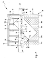
- One of the carrying device 42 is shown in detail in FIG. 3: the carrying device 42 shown there comprises an adapter piece 44, which in plan view (arrow 46 in FIG. 3) having circular cylindrical cross section.
- the adapter piece 44 is made of plastic and inserted into a complementary receiving opening 48 which is present in the support table 38.
- a height of the adapter piece 44 corresponds to the depth of the receiving opening 48 certain game is used.
- Via a channel 58 the recess 54 is connected to a compressed air supply 60, which is present in the discharge table 34.
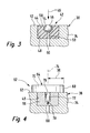
- the second stop 64 is attached to the support table 38 at this point.
- the second stop 64 has an intermediate piece 66 whose outer shape is the same as the outer shape of the adapter piece 44 of the support means 42.
- the intermediate piece 66 is made of metal, for example made of brass. It is snugly inserted into the receiving opening 48 at the position 62.
- the second stop 64 further comprises a stop element 68 which has a contact portion 70 and a fastening portion 72 connected thereto.
- the contact portion 70 is designed as a cylindrical disc with a plane perpendicular to the plane 52 of the support table 38 cylinder axis 74. It is mounted relative to the mounting portion 72 about the axis 74 rotatably.
- the attachment portion 72 is formed as a pin, which is inserted snugly into a corresponding opening 76 in the intermediate piece 66.
- the opening 76 is designed as a blind hole, at the bottom of a threaded hole 78 is also present as a blind hole, which has a Representing attacking section. Its function will be discussed below.
- the sawing device 10 further has a pressure bar 80, which is arranged above the saw table 16 and can be moved vertically.
- a laser device 88 Arranged on the pressure bar 80 is a laser device 88 which projects a cutting line 90 of the movable saw 26 onto the saw table 16 or the workpiece 15 lying in this area.
- a control and regulating device 82 which controls the operation of the sawing device 10 and controls. Part of the control and regulating device 82 are a monitor 84 and an input unit 86.
- the sawing device 10 is operated as follows: first, the user of the sawing device 10 at a desired position (in Figures 1 and 2 at reference numeral 62) there existing support means 42 from the receiving opening 48 in the removal table 34 is removed. Then, at this position 62, first the intermediate piece 66 is inserted, and in the opening 76 of the stop element 68 is then used with the pin-like mounting portion 72. Since this is somewhat shorter axially than the opening 76 is long, the cylindrical contact portion 70 is flush on the discharge table 34, as shown in Figure 4.
- the individual receiving openings 48 in the discharge table 34 are provided with identification numbers.
- the user of the sawing device 10 now enters the identification number of that receiving opening 48 via the input unit 86 in the control and regulating device 82, in which the second stop 64 is attached. He also gives one desired angle (reference numeral 92 in Figures 1 and 2), which the cutting line 90 of the separation saw to be carried out by the separating cut 26 against a longitudinal edge 94 of the workpiece 40 should have. It is also conceivable, of course, to relate the angle to another edge of the workpiece.
- the corresponding position on the support table 38 or the unloading table 34 is stored for each identification number of a receiving opening 48.
- the control and regulating device 82 calculates a corresponding position of the first stop 30, and the controller 82 controls the saw carriage 22 so that the first stopper 30 is moved parallel to the cutting line 90 to the calculated position.
- the first stop 30 is brought by the control and regulating device 82 in its working position.
- the user of the sawing device 10 can bring the workpiece 15 with the longitudinal edge 94 in abutment against the first stop 30 and to the second stop 64.
- This longitudinal edge 94 now extends along a tangent to the two stops 30 and 64.
- it switches on the laser device 88, which projects the cutting line 90 onto the workpiece 15.
- the user now moves the workpiece 15 along the two stops 30 and 64, ie parallel said tangent until the projected cutting line 90 is located at the desired location on the workpiece 15.
- the user causes by a corresponding input to the control and regulating device 82, the performance of a saw cut: this is first of the control and regulating device 82, the pressure bar 80 is lowered onto the workpiece 15 and this thus jammed between the pressure bar 80 and saw table 16. Then, the first stop 30 is pivoted by the control and regulating device 82 from its working position into the release position, in which it is positioned below the level of the saw table 16, so it no longer projects beyond the top of the support table 38. Thereafter, the scoring saw 24 and the dicing saw 26 are moved upward and the saw carriage 22 is moved along the cutting direction 28, whereby the workpiece 15 along the cutting line 90 is pre-scored and then separated. Then, the pressure bar 80 is lifted by the control and regulating device 82, so that the user can remove the workpiece 15 and the separated remainder from the sawing device 10.
- the user first pulls the stop element 68 out of the intermediate piece 66. Then he screws a corresponding tool (not shown) in the threaded hole 78 and pulls the spacer 66 from the receiving opening 48 out. He then puts the previously removed and intermediately stored support means 42 back into the receiving opening 48.
- the second stop 64 can be inserted into any of the receiving openings 48.
- control and regulating device 82 has detected the current position of the second stop 64 due to the identification number of the corresponding receiving opening 48. It is also possible that each receiving opening 48, in which the second stop 64 can be used, a detection device is assigned, which can transmit a signal to the control and regulating device, from which they can determine the current position of the second stop 64.
- those receiving openings 48 "normally" provided for receiving the carrying means 42 were used. It is understood that in an embodiment not shown, special receiving openings for the positioning of the second stop may be present, so that previously a support means 42 does not need to be removed extra.
- the sawing device 10 has an additional stop 98 in the form of a simple board, which is jammed between the collets 20 of the feed device 18.
- a corner 100 of the workpiece 15 pointing to the feed device 18 can be applied to this additional stop 98, which improves the accuracy of the positioning of the workpiece 15.
- FIG. An alternative embodiment is further illustrated in FIG. It is true that such elements and areas, the equivalent functions to previously described elements and areas that bear the same reference numerals and are not explained again in detail.
- the second stop 64 there comprises an attachment rail 102 against which the longitudinal edge 94 of the workpiece 15 rests.
- a displaceable Positionseinstellelement 104 is mounted on the locating rail 102, which cooperates with a length scale 106 on the locating rail 102, and on which a rear edge 108 of the workpiece 15 abuts. This makes it possible to successively perform several cuts at the same angle and to move the workpiece 15 by a precise, readable on the length scale 106 and predetermined by the position setting 104 distance between the individual sections.
- the clip rail 102 may be formed either as a separate part, which can be connected in a suitable and releasable manner with the stop element 68, or the clip rail is an integral part of the stop element, thus forming this.
Abstract
Description
Die Erfindung betrifft eine Sägeeinrichtung nach dem Oberbegriff des Anspruchs 1.The invention relates to a sawing device according to the preamble of claim 1.
Die
Aufgabe der vorliegenden Erfindung ist es, eine Sägeeinrichtung der eingangs genannten Art zu schaffen, welche möglichst einfach baut und preiswert hergestellt werden kann. Sie soll darüber hinaus einfach betrieben werden können.Object of the present invention is to provide a sawing device of the type mentioned, which is as simple as possible and can be manufactured inexpensively. It should also be easy to operate.
Diese Aufgabe wird durch eine Sägeeinrichtung mit den Merkmalen des Anspruchs 1 gelöst. Vorteilhafte Weiterbildungen der Erfindung sind in Unteransprüchen angegeben. Für die Erfindung wesentliche Merkmale finden sich darüber hinaus in der nachfolgenden Beschreibung und in der Zeichnung. Dabei können die erwähnten Merkmale in ganz unterschiedlichen Kombinationen für die Erfindung wesentlich sein, ohne dass hierauf jeweils explizit hingewiesen wird.This object is achieved by a sawing device with the features of claim 1. Advantageous developments of the invention are specified in subclaims. For the invention essential features are also found in the following description and in the drawing. In this case, the features mentioned in very different combinations for the invention may be essential, without being explicitly pointed out.
Bei der erfindungsgemäßen Sägeeinrichtung ist der zweite Anschlag am Auflagetisch befestigt, also gegenüber dem Auflagetisch "stationär". Daher baut eine Vorschubvorrichtung der erfindungsgemäßen Sägeeinrichtung einfacher, was die Herstellkosten senkt. Darüber hinaus baut ein solcher stationärer Anschlag einfacher, und er kann von einem Benutzer der Sägeeinrichtung einfacher angewendet werden. Eine aufwändige Programmierung bzw. Positionierung der Vorschubvorrichtung ist für die Durchführung eines schräg verlaufenden Schnittes nicht mehr erforderlich. Die Handhabung und Bedienung der erfindungsgemäßen Sägeeinrichtung ist daher einfach. Ferner ist der Auflagetisch ein massives Teil, welches eine sichere Positionierung des zweiten Anschlags gewährleisten kann. Hierdurch wird die Vorschubvorrichtung der Sägeeinrichtung entlastet.In the sawing device according to the invention, the second stop is attached to the support table, ie "stationary" relative to the support table. Therefore, a feeding device of the sawing device according to the invention simplifies, which lowers the manufacturing costs. In addition, such a stationary stop makes easier, and it can be easily applied by a user of the sawing device. An elaborate programming or positioning of the feed device is no longer necessary for the implementation of an oblique cut. The handling and operation of the sawing device according to the invention is therefore simple. Furthermore, the support table is a solid part, which ensure a secure positioning of the second stop can. As a result, the feed device of the sawing device is relieved.
Die Sägeeinrichtung gemäß Anspruch 2 ist leicht bedienbar, robust und kostengünstig herstellbar.The sawing device according to claim 2 is easy to use, robust and inexpensive to produce.
Vorteil der Sägeeinrichtung nach Anspruch 3 ist, dass ein seitlicher Rand eines Werkstücks präzise und ohne die Gefahr von Beschädigungen an den zweiten Anschlag angelegt werden kann.Advantage of the sawing device according to claim 3, that a lateral edge of a workpiece can be applied precisely and without the risk of damage to the second stop.
Wird die Sägeeinrichtung gemäß Anspruch 4 ausgestaltet, kann der Anlegeabschnitt einen größeren Durchmesser haben als der Befestigungsabschnitt, was das Risiko von Beschädigungen am Werkstück nochmals senkt.If the sawing device is designed according to claim 4, the application section can have a larger diameter than the attachment section, which further reduces the risk of damage to the workpiece.
Ist die Sägeeinrichtung gemäß Anspruch 5 ausgebildet, kann die im Auflagetisch vorhandene Aufnahmeöffnung für unterschiedliche Zwecke eingesetzt werden. Eine solche Sägeeinrichtung ist daher besonders flexibel. Das erfindungsgemäß vorgesehene Zwischenstück hat die Funktion eines Adapterelements.If the sawing device is designed according to claim 5, the receiving opening provided in the support table can be used for different purposes. Such a sawing device is therefore particularly flexible. The inventively provided intermediate piece has the function of an adapter element.
Vor allem dann, wenn das Zwischenstück bündig mit der Oberseite des Auflagetisches angeordnet ist, verbessert die Sägeeinrichtung gemäß Anspruch 6 die Handhabung. Die Zeit, die zum Umrüsten einer solchen Sägeeinrichtung erforderlich ist, ist dann besonders kurz.Especially when the intermediate piece is arranged flush with the top of the support table, the sawing device according to claim 6 improves the handling. The time required to convert such a sawing device is then particularly short.
Vorteil der Weiterbildung gemäß Anspruch 7 ist eine nochmalige Reduzierung des Beschädigungsrisikos einer seitlichen Kante eines Werkstücks, welches am Anlegeabschnitt anliegt und verschoben wird.Advantage of the development according to claim 7 is a further reduction of the risk of damage to a lateral edge of a workpiece, which rests on the application section and is moved.
Durch die Vielzahl von Aufnahmeöffnungen gemäß Anspruch 8 kann die erfindungsgemäßen Sägeeinrichtung für Werkstücke ganz unterschiedlicher Größe und ganz unterschiedlicher geometrischer Gestalt eingesetzt werden.Due to the large number of receiving openings according to claim 8, the sawing device according to the invention for workpieces of very different sizes and very different geometric shape can be used.
Die Zusatzkosten, die für die Befestigung des zweiten Anschlags am Auflagetisch aufzuwenden sind, sind bei der Weiterbildung gemäß Anspruch 9 minimal, da als Aufnahmeöffnungen die bei üblichen Auflagetischen ohnehin vorhandenen Aufnahmeöffnungen für Trageinrichtungen, beispielsweise Kugellager und/oder Luftkissenlager, verwendet werden.The additional costs that are expended for the attachment of the second stop on the support table are minimal in the development according to claim 9, since as receiving openings in existing support tables already existing receiving openings for carrying devices, such as ball bearings and / or air cushion bearings are used.
Bei der Sägeeinrichtung gemäß Anspruch 11 können kurze Taktzeiten realisiert werden, was die Wirtschaftlichkeit der Sägeeinrichtung erhöht.In the sawing device according to claim 11 short cycle times can be realized, which increases the efficiency of the sawing device.
Vorteil der Sägeeinrichtung gemäß Anspruch 12 ist, dass das Risiko von Fehlschnitten reduziert wird. In die gleiche Richtung zielt die Sägeeinrichtung gemäß Anspruch 13.Advantage of the sawing device according to
Die Durchführung des eigentlichen Sägeschnittes wird durch eine Sägeeinrichtung mit den Merkmalen des Anspruchs 14 erleichtert, die Genauigkeit beim eigentlichen Sägevorgang erhöhen.The implementation of the actual saw cut is facilitated by a sawing device with the features of
Eine Sägeeinrichtung mit den Merkmalen des Anspruchs 15 kann sehr variabel eingesetzt werden, da der erste Anschlag in der Freigabestellung die Positionierung des Werkstücks auf dem Auflagetisch nicht beeinträchtigen kann.A sawing device with the features of
Die Kosten für die Herstellung der Sägeeinrichtung sind bei solchen Sägeeinrichtungen mit den Merkmalen der Ansprüche 16 und 17 besonders niedrig.The costs for the production of the sawing device are particularly low in such sawing devices with the features of
Eine Sägeeinrichtung mit den Merkmalen der Ansprüche 18 und 19 ermöglicht auf einfache Art und Weise die Durchführung aufeinanderfolgender Schnitte mit dem gleichen Winkel.A sawing device with the features of
Durch die Weiterbildungen der Ansprüche 20 und 21 wird die Positioniergenauigkeit des Werkstücks erhöht und die Positionierung erleichtert.By the developments of
Nachfolgend wird ein besonders bevorzugtes Ausführungsbeispiel der vorliegenden Erfindung unter Bezugnahme auf die beiliegende Zeichnung näher erläutert. In der Zeichnung zeigen:
- Figur 1
- eine Draufsicht auf eine erste Ausführungsform einer Sägeeinrichtung;
- Figur 2
- eine perspektivische Darstellung eines Bereichs der Sägeeinrichtung von Figur 1;
- Figur 3
- einen Schnitt durch eine Trageinrichtung eines Auflagetisches der Sägeeinrichtung von Figur 1;
- Figur 4
- einen Schnitt ähnlich Figur 3 eines zweiten Anschlags der Sägeeinrichtung von Figur 1; und
- Figur 5
- eine Draufsicht auf einen Bereich einer zweiten Ausführungsform einer Sägeeinrichtung..
- FIG. 1
- a plan view of a first embodiment of a sawing device;
- FIG. 2
- a perspective view of a portion of the sawing of Figure 1;
- FIG. 3
- a section through a support means of a support table of the sawing of Figure 1;
- FIG. 4
- a section similar to Figure 3 of a second stop of the sawing of Figure 1; and
- FIG. 5
- a plan view of a portion of a second embodiment of a sawing ..
Eine Sägeeinrichtung trägt in den Figuren 1 und 2 insgesamt das Bezugszeichen 10. Sie umfasst einen Zuführtisch 12 mit Rollen 14, durch die ein Werkstück 15 einem Sägetisch 16 zugeführt werden kann. Hierzu verfügt die Sägeeinrichtung 10 über eine Vorschubvorrichtung 18 mit Spannzangen 20.A sawing device carries in FIGS. 1 and 2 the
Der Sägetisch 16 umfasst einen Sägewagen 22 mit einer Vorritzsäge 24 und einer Trennsäge 26. Der Sägewagen 22 ist längs einer Schnittrichtung (Pfeil 28) bewegbar.The saw table 16 comprises a saw carriage 22 with a
Am Sägewagen 22 ist ferner ein erster Anschlag 30 montiert. Dieser ist als längliches Schwert ausgeführt, welches eine in den Figuren 1 und 2 dargestellte Arbeitsstellung aufweist, in der es aus einem Sägespalt 32 über eine Ebene des Sägetisches 16 übersteht. Der erste Anschlag 30 kann jedoch von der Arbeitsstellung in eine Freigabestellung verschwenkt werden, in der er unterhalb der Ebene des Sägetisches 16 positioniert ist. Ähnliches gilt auch für die Vorritzsäge 24 und die Trennsäge 26: auch diese können aus einer Freigabestellung, in der sie unterhalb der Ebene des Sägetisches 16 angeordnet sind, in eine Arbeitsstellung nach oben bewegt werden, in der sie über die Ebene des Sägetisches 16 überstehen.On the saw carriage 22, a
Auf der vom Zuführtisch 12 abgewandten Seite des Sägetisches 16 ist ein Entnahmetisch 34 angeordnet. Dieser besteht aus mehreren Elementen 36a bis 36f. Die Ebene der Oberseite des Entnahmetisches 34 ist auf gleicher Höhe wie die Ebene der Oberseite des Sägetisches 16 und die Ebene der Oberseite des Zuführtisches 12. Der Zuführtisch 12, der Sägetisch 16 und der Entnahmetisch 34 bilden insgesamt einen Auflagetisch 38. Auf diesen kann das Werkstück 15 aufgelegt werden.On the side facing away from the feed table 12 side of the saw table 16, a discharge table 34 is arranged. This consists of
Der Entnahmetisch 34 umfasst eine Vielzahl von identischen Trageinrichtungen 42, von denen aus Gründen der Übersichtlichkeit in den Figuren 1 und 2 jeweils nur eine mit einem Bezugszeichen versehen ist. Eine der Trageinrichtung 42 ist im Detail in in Figur 3 gezeigt: die dort gezeigte Trageinrichtung 42 umfasst ein Adapterstück 44, welches in der Draufsicht (Pfeil 46 in Figur 3) kreiszylindrischen Querschnitt aufweist. Das Adapterstück 44 ist aus Kunststoff und in eine komplementäre Aufnahmeöffnung 48 eingesetzt, die im Auflagetisch 38 vorhanden ist. Die Höhe des Adapterstücks 44 entspricht der Tiefe der Aufnahmeöffnung 48. Eine Oberseite 50 des Adapterstücks 44 ist also bündig mit einer Oberseite 52 des zum Auflagetisch 38 gehörenden Entnahmetisches 34. In dem Adapterstück 44 ist eine Ausnehmung 54 vorhanden, in die eine Kugel 56 mit einem gewissen Spiel eingesetzt ist. Über einen Kanal 58 ist die Ausnehmung 54 mit einer Druckluftzuführung 60 verbunden, die im Entnahmetisch 34 vorhanden ist.The removal table 34 includes a plurality of identical support means 42, of which, for reasons of clarity in the figures 1 and 2 only one is provided with a reference numeral. One of the carrying
An einer Position 62 (siehe Figuren 1 und 2) wurde die Trageinrichtung 42 entfernt. Statt dessen ist an dieser Stelle ein zweiter Anschlag 64 am Auflagetisch 38 befestigt. Dies ist in Figur 4 dargestellt: der zweite Anschlag 64 verfügt über ein Zwischenstück 66, dessen Außenform gleich ist wie die Außenform des Adapterstücks 44 der Trageinrichtung 42. Das Zwischenstück 66 ist aus Metall hergestellt, beispielsweise aus Messing. Es ist im Passsitz in die Aufnahmeöffnung 48 an der Position 62 eingesetzt.At a position 62 (see Figures 1 and 2), the
Der zweite Anschlag 64 umfasst ferner ein Anschlagelement 68, welches einen Anlegeabschnitt 70 und einen mit diesem verbundenen Befestigungsabschnitt 72 aufweist. Der Anlegeabschnitt 70 ist als zylindrische Scheibe ausgeführt mit einer zur Ebene 52 des Auflagetisches 38 rechtwinkligen Zylinderachse 74. Er ist gegenüber dem Befestigungsabschnitt 72 um die Achse 74 drehbar gelagert. Der Befestigungsabschnitt 72 ist als Zapfen ausgebildet, welcher im Passsitz in eine entsprechende Öffnung 76 im Zwischenstück 66 eingesetzt ist. Die Öffnung 76 ist als Sackloch ausgeführt, an dessen Boden ebenfalls als Sackloch eine Gewindebohrung 78 vorhanden ist, welche einen Angreifabschnitt darstellt. Auf dessen Funktion wird weiter unten noch eingegangen werden.The
Die Sägeeinrichtung 10 verfügt ferner über einen Druckbalken 80, der oberhalb des Sägetisches 16 angeordnet ist und vertikal bewegt werden kann. Am Druckbalken 80 ist eine Lasereinrichtung 88 angeordnet, welche eine Schnittlinie 90 der beweglichen Säge 26 auf den Sägetisch 16 beziehungsweise das in diesem Bereich liegende Werkstück 15 projiziert. Ferner gehört zu der Sägeeinrichtung 10 eine Steuer- und Regeleinrichtung 82, welche den Betrieb der Sägeeinrichtung 10 steuert und regelt. Teil der Steuer- und Regeleinrichtung 82 sind ein Monitor 84 sowie eine Eingabeeinheit 86.The sawing
Die Sägeeinrichtung 10 wird folgendermaßen betrieben: zunächst wird vom Benutzer der Sägeeinrichtung 10 an einer gewünschten Position (in den Figuren 1 und 2 beim Bezugszeichen 62) die dort vorhandene Trageinrichtung 42 aus der Aufnahmeöffnung 48 im Entnahmetisch 34 entfernt. Dann wird an dieser Position 62 zunächst das Zwischenstück 66 eingesetzt, und in dessen Öffnung 76 wird dann das Anschlagelement 68 mit dem zapfenartigen Befestigungsabschnitt 72 eingesetzt. Da dieser axial etwas kürzer ist als die Öffnung 76 lang ist, liegt der zylindrische Anlegeabschnitt 70 bündig auf dem Entnahmetisch 34 auf, wie dies auch in Figur 4 dargestellt ist.The sawing
Die einzelnen Aufnahmeöffnungen 48 im Entnahmetisch 34 sind mit Identifikationsnummern versehen. Der Benutzer der Sägeeinrichtung 10 gibt nun die Identifikationsnummer jener Aufnahmeöffnung 48 über die Eingabeeinheit 86 in die Steuer-und Regeleinrichtung 82 ein, in der der zweite Anschlag 64 befestigt ist. Außerdem gibt er einen gewünschten Winkel (Bezugszeichen 92 in den Figuren 1 und 2) ein, den die Schnittlinie 90 des von der Trennsäge 26 durchzuführenden Trennschnittes gegenüber einem Längsrand 94 des Werkstücks 40 haben soll. Denkbar ist natürlich auch, den Winkel auf einen anderen Rand des Werkstücks zu beziehen.The
Auf einem Speicher der Steuer- und Regeleinrichtung 82 ist für jede Identifikationsnummer einer Aufnahmeöffnung 48 die entsprechende Position auf dem Auflagetisch 38 beziehungsweise dem Entnahmetisch 34 hinterlegt. Aus der Position 62 der vorliegend gewählten Aufnahmeöffnung 48 auf dem Auflagetisch 38, dem Radius 96 (vgl. Figur 4) des Anlegeabschnitts 70 des zweiten Anschlags 64 und dem gewünschten Winkel 92 berechnet die Steuer-und Regeleinrichtung 82 eine entsprechende Position des ersten Anschlags 30, und die Steuer-und Regeleinrichtung 82 steuert den Sägewagen 22 so an, dass der erste Anschlag 30 parallel zur Schnittlinie 90 in die berechnete Position bewegt wird. Außerdem wird der erste Anschlag 30 von der Steuer-und Regeleinrichtung 82 in seine Arbeitsstellung gebracht.On a memory of the control and regulating
Nun kann der Benutzer der Sägeeinrichtung 10 das Werkstück 15 mit dem Längsrand 94 in Anlage an den ersten Anschlag 30 und an den zweiten Anschlag 64 bringen. Dieser Längsrand 94 verläuft nun längs einer Tangente an die beiden Anschläge 30 und 64. Gleichzeitig schaltet er die Lasereinrichtung 88 ein, welche die Schnittlinie 90 auf das Werkstück 15 projiziert. Der Benutzer verschiebt nun das Werkstück 15 längs der beiden Anschläge 30 und 64, also parallel besagter Tangente soweit, bis die projizierte Schnittlinie 90 an der gewünschten Stelle am Werkstück 15 liegt.Now the user of the
Dann veranlasst der Benutzer durch eine entsprechende Eingabe an der Steuer- und Regeleinrichtung 82 die Durchführung eines Sägeschnittes: hierzu wird von der Steuer- und Regeleinrichtung 82 zunächst der Druckbalken 80 auf das Werkstück 15 abgesenkt und dieses somit zwischen Druckbalken 80 und Sägetisch 16 verklemmt. Dann wird der erste Anschlag 30 von der Steuer-und Regeleinrichtung 82 von seiner Arbeitsstellung in die Freigabestellung verschwenkt, in der er unterhalb der Ebene des Sägetisches 16 positioniert ist, er also nicht mehr über die Oberseite des Auflagetisches 38 übersteht. Danach werden die Vorritzsäge 24 und die Trennsäge 26 nach oben bewegt und der Sägewagen 22 längs der Schnittrichtung 28 bewegt, wodurch das Werkstück 15 längs der Schnittlinie 90 vorgeritzt und anschließend getrennt wird. Dann wird der Druckbalken 80 von der Steuer-und Regeleinrichtung 82 angehoben, so dass der Benutzer das Werkstück 15 und den abgetrennten Rest aus der Sägeeinrichtung 10 entnehmen kann.Then, the user causes by a corresponding input to the control and regulating
Sollen keine schrägen Schnitte mehr durchgeführt werden, zieht der Benutzer zunächst das Anschlagelement 68 aus dem Zwischenstück 66 heraus. Dann schraubt er ein entsprechendes Werkzeug (nicht dargestellt) in die Gewindebohrung 78 ein und zieht das Zwischenstück 66 aus der Aufnahmeöffnung 48 heraus. Anschließend setzt er die zuvor herausgenommene und zwischengelagerte Trageinrichtung 42 wieder in die Aufnahmeöffnung 48 ein.If no more oblique cuts are to be made, the user first pulls the
Soll ein schräger Schnitt an einem Werkstück 15 durchgeführt werden, welches andere geometrischen Abmessungen aufweist, kann der zweite Anschlag 64 in jede beliebige der Aufnahmeöffnungen 48 eingesetzt werden.If an oblique cut is to be made on a
Bei dem oben beschriebenen Ausführungsbeispiel hat die Steuer-und Regeleinrichtung 82 die aktuelle Lage des zweiten Anschlags 64 aufgrund der Identifikationsnummer der entsprechenden Aufnahmeöffnung 48 erkannt. Möglich ist aber auch, dass jeder Aufnahmeöffnung 48, in die der zweite Anschlag 64 eingesetzt werden kann, eine Erfassungseinrichtung zugeordnet ist, welche ein Signal an die Steuer-und Regeleinrichtung übermitteln kann, aus dem diese die aktuelle Lage des zweiten Anschlags 64 ermitteln kann.In the embodiment described above, the control and regulating
Ferner wurden bei dem obigen Ausführungsbeispiel für die Positionierung des zweiten Anschlags 64 jene Aufnahmeöffnungen 48 verwendet, die "normalerweise" für die Aufnahme der Trageinrichtungen 42 vorgesehen sind. Es versteht sich, dass bei einer nicht gezeigten Ausführungsform auch spezielle Aufnahmeöffnungen für die Positionierung des zweiten Anschlags vorhanden sein können, so dass zuvor eine Trageinrichtung 42 nicht extra entfernt werden muss.Further, in the above embodiment, for positioning the
In Figur 1 ist außerdem eine zusätzliche Variante gestrichelt gezeichnet: Bei dieser verfügt die Sägeeinrichtung 10 über einen Zusatzanschlag 98 in Form eines einfachen Bretts, welches zwischen den Spannzangen 20 der Vorschubvorrichtung 18 verklemmt ist. An diesem Zusatzanschlag 98 kann zusätzlich ein zur Vorschubvorrichtung 18 zeigendes Eck 100 des Werkstücks 15 angelegt werden, was die Genauigkeit der Positionierung des Werkstücks 15 verbessert.In Figure 1, an additional variant is also shown in dashed lines: In this, the sawing
Eine alternative Ausführungsform ist ferner in Figur 5 dargestellt. Dabei gilt, dass solche Elemente und Bereiche, die äquivalente Funktionen zu vorab beschriebenen Elementen und Bereichen aufweisen, die gleichen Bezugszeichen tragen und nicht nochmals im Detail erläutert sind.An alternative embodiment is further illustrated in FIG. It is true that such elements and areas, the equivalent functions to previously described elements and areas that bear the same reference numerals and are not explained again in detail.
Man erkennt aus Figur 5, dass der dortige zweite Anschlag 64 eine Anlegeschiene 102 umfasst, an der der Längsrand 94 des Werkstücks 15 anliegt. Auf der Anlegeschiene 102 ist ein verschiebbares Positionseinstellelement 104 montiert, welches mit einer Längenskala 106 auf der Anlegeschiene 102 zusammenarbeitet, und an dem ein hinterer Rand 108 des Werkstücks 15 anliegt. Dies gestattet es, aufeinanderfolgend mehrere Schnitte mit gleichem Winkel durchzuführen und zwischen den einzelnen Schnitten das Werkstück 15 um eine präzise, an der Längenskala 106 ablesbare und durch das Positionseinstellelement 104 vorgebbare Distanz zu verschieben. Die Anlegeschiene 102 kann entweder als separates Teil ausgebildet sein, welches auf geeignete und lösbare Art und Weise mit dem Anschlagelement 68 verbunden werden kann, oder die Anlegeschiene ist integraler Bestandteil des Anschlagelements, bildet also dieses.It can be seen from FIG. 5 that the
Claims (21)
Applications Claiming Priority (1)
| Application Number | Priority Date | Filing Date | Title |
|---|---|---|---|
| DE200610013264 DE102006013264A1 (en) | 2006-03-21 | 2006-03-21 | sawing |
Publications (3)
| Publication Number | Publication Date |
|---|---|
| EP1837141A2 true EP1837141A2 (en) | 2007-09-26 |
| EP1837141A3 EP1837141A3 (en) | 2007-11-21 |
| EP1837141B1 EP1837141B1 (en) | 2013-06-19 |
Family
ID=38181181
Family Applications (1)
| Application Number | Title | Priority Date | Filing Date |
|---|---|---|---|
| EP20070000404 Active EP1837141B1 (en) | 2006-03-21 | 2007-01-10 | Sawing device |
Country Status (2)
| Country | Link |
|---|---|
| EP (1) | EP1837141B1 (en) |
| DE (1) | DE102006013264A1 (en) |
Cited By (5)
| Publication number | Priority date | Publication date | Assignee | Title |
|---|---|---|---|---|
| EP2251127A1 (en) * | 2009-05-15 | 2010-11-17 | Wilhelm Altendorf GmbH & Co. KG | Wood processing machine with air cushion table |
| ITBO20090439A1 (en) * | 2009-07-08 | 2011-01-09 | Biesse Spa | CUTTING MACHINE FOR WOODEN PANELS OR THE LIKE |
| ITMI20091774A1 (en) * | 2009-10-15 | 2011-04-16 | Macotec S R L | MACHINE FOR CUTTING GLASS SHEETS AND SIMILAR, WITH MEANS FOR ROTATION OF AT LEAST ONE PORTION OF SLAB. |
| WO2012004288A1 (en) | 2010-07-06 | 2012-01-12 | Holzma Plattenaufteiltechnik Gmbh | Panel-dividing system |
| EP3450090A1 (en) | 2017-05-18 | 2019-03-06 | Wilhelm Altendorf GmbH & Co. KG | Air-cushion table |
Families Citing this family (2)
| Publication number | Priority date | Publication date | Assignee | Title |
|---|---|---|---|---|
| ITRM20110466A1 (en) | 2011-09-08 | 2013-03-09 | Scm Group Spa | CUTTING MACHINE AND ITS FUNCTIONING METHOD. |
| DE102021116333A1 (en) * | 2021-06-24 | 2022-12-29 | Homag Gmbh | Guide device at the machine inlet or machine outlet and processing machine |
Citations (1)
| Publication number | Priority date | Publication date | Assignee | Title |
|---|---|---|---|---|
| WO2002026452A1 (en) * | 2000-09-22 | 2002-04-04 | Ant. Panhans Werkzeug- Und Maschinenfabrik Gesellschaft M.B.H. | Panel dividing saw having an angularly adjustable bearing device |
Family Cites Families (1)
| Publication number | Priority date | Publication date | Assignee | Title |
|---|---|---|---|---|
| DE10223142B4 (en) * | 2002-05-15 | 2005-12-29 | Reich Spezialmaschinen Gmbh | sawing |
-
2006
- 2006-03-21 DE DE200610013264 patent/DE102006013264A1/en not_active Withdrawn
-
2007
- 2007-01-10 EP EP20070000404 patent/EP1837141B1/en active Active
Patent Citations (1)
| Publication number | Priority date | Publication date | Assignee | Title |
|---|---|---|---|---|
| WO2002026452A1 (en) * | 2000-09-22 | 2002-04-04 | Ant. Panhans Werkzeug- Und Maschinenfabrik Gesellschaft M.B.H. | Panel dividing saw having an angularly adjustable bearing device |
Cited By (6)
| Publication number | Priority date | Publication date | Assignee | Title |
|---|---|---|---|---|
| EP2251127A1 (en) * | 2009-05-15 | 2010-11-17 | Wilhelm Altendorf GmbH & Co. KG | Wood processing machine with air cushion table |
| ITBO20090439A1 (en) * | 2009-07-08 | 2011-01-09 | Biesse Spa | CUTTING MACHINE FOR WOODEN PANELS OR THE LIKE |
| EP2272642A1 (en) * | 2009-07-08 | 2011-01-12 | BIESSE S.p.A. | Machine for cutting panels made of wood or the like |
| ITMI20091774A1 (en) * | 2009-10-15 | 2011-04-16 | Macotec S R L | MACHINE FOR CUTTING GLASS SHEETS AND SIMILAR, WITH MEANS FOR ROTATION OF AT LEAST ONE PORTION OF SLAB. |
| WO2012004288A1 (en) | 2010-07-06 | 2012-01-12 | Holzma Plattenaufteiltechnik Gmbh | Panel-dividing system |
| EP3450090A1 (en) | 2017-05-18 | 2019-03-06 | Wilhelm Altendorf GmbH & Co. KG | Air-cushion table |
Also Published As
| Publication number | Publication date |
|---|---|
| EP1837141B1 (en) | 2013-06-19 |
| EP1837141A3 (en) | 2007-11-21 |
| DE102006013264A1 (en) | 2007-09-27 |
Similar Documents
| Publication | Publication Date | Title |
|---|---|---|
| DE60204941T2 (en) | WINDOW LOCKABLE DETACHABLE PUNCH AND MATRIZE JACK IN HOLDING DEVICE | |
| EP1837141B1 (en) | Sawing device | |
| EP1196269B1 (en) | Device for die cutting a stack consisting of sheet-type materials | |
| EP2101943B1 (en) | Tool holder, particularly for a burring tool, and cutting element for a tool holder | |
| EP1815931B1 (en) | Scoring saw blades and their adjustment method | |
| CH649936A5 (en) | DEVICE FOR BEVELING A WORKPIECE EDGE. | |
| EP2193894B1 (en) | Method for sawing up at least one board | |
| EP1136204A2 (en) | Apparatus for severing endless profiles | |
| DE102008001399A1 (en) | Flat keyhole jigsaw blade, has elongated saw blade body provided with clamping shank and saw blade tip, and pull linkage provided along longitudinal axis of jigsaw blade and extending transverse over toothed lathe up to saw blade ridges | |
| EP0524270B1 (en) | Device for vee-grafting | |
| DE10029195C1 (en) | Device, to cut rod-shaped work piece, especially hollow profile, has cutting block to hold work piece, adjustable knife guided in cutting block and holder block fitted in work piece as counter bearing | |
| DE3834096A1 (en) | Apparatus and process for producing a device for machining panel-type workpieces or the like | |
| DE10317015A1 (en) | Arrangement for stamping workpieces, has stamping blades arranged along stamping opening, ejection element movably guided relative to carrying element and pressure element above carrying element | |
| WO2019057658A1 (en) | Method for processing workpieces, computer program product, and workpiece processing system | |
| EP3090846B1 (en) | Board machining device | |
| DE102018003622A1 (en) | Device and method for cutting out a workpiece | |
| DE202018002305U1 (en) | Device for separating a workpiece | |
| DE3009813C2 (en) | Scoring bar for installation in a knife shaft of a wood cutting machine | |
| EP1365899A2 (en) | Method and device for reducing round timber that is bent in one plane to wood products | |
| DE19626127A1 (en) | Joinery machine for processing bar-shaped wooden workpieces | |
| DE102021110333A1 (en) | Preparatory method for preparing the division of at least two workpieces, computer program product, computer-readable storage medium, and panel dividing system | |
| EP2808112A1 (en) | Device for guiding board-shaped workpieces | |
| DE202018105116U1 (en) | Mounting arrangement on a cutterhead | |
| EP0173042A1 (en) | Punching device, especially for abrasive paper or abrasive cloth | |
| DE1746771U (en) | KNIFE HEAD FOR MACHINERY. |
Legal Events
| Date | Code | Title | Description |
|---|---|---|---|
| PUAI | Public reference made under article 153(3) epc to a published international application that has entered the european phase |
Free format text: ORIGINAL CODE: 0009012 |
|
| AK | Designated contracting states |
Kind code of ref document: A2 Designated state(s): AT BE BG CH CY CZ DE DK EE ES FI FR GB GR HU IE IS IT LI LT LU LV MC NL PL PT RO SE SI SK TR |
|
| AX | Request for extension of the european patent |
Extension state: AL BA HR MK YU |
|
| PUAL | Search report despatched |
Free format text: ORIGINAL CODE: 0009013 |
|
| AK | Designated contracting states |
Kind code of ref document: A3 Designated state(s): AT BE BG CH CY CZ DE DK EE ES FI FR GB GR HU IE IS IT LI LT LU LV MC NL PL PT RO SE SI SK TR |
|
| AX | Request for extension of the european patent |
Extension state: AL BA HR MK YU |
|
| 17P | Request for examination filed |
Effective date: 20071220 |
|
| 17Q | First examination report despatched |
Effective date: 20080229 |
|
| AKX | Designation fees paid |
Designated state(s): AT BE BG CH CY CZ DE DK EE ES FI FR GB GR HU IE IS IT LI LT LU LV MC NL PL PT RO SE SI SK TR |
|
| GRAP | Despatch of communication of intention to grant a patent |
Free format text: ORIGINAL CODE: EPIDOSNIGR1 |
|
| GRAS | Grant fee paid |
Free format text: ORIGINAL CODE: EPIDOSNIGR3 |
|
| GRAA | (expected) grant |
Free format text: ORIGINAL CODE: 0009210 |
|
| AK | Designated contracting states |
Kind code of ref document: B1 Designated state(s): AT BE BG CH CY CZ DE DK EE ES FI FR GB GR HU IE IS IT LI LT LU LV MC NL PL PT RO SE SI SK TR |
|
| REG | Reference to a national code |
Ref country code: GB Ref legal event code: FG4D Free format text: NOT ENGLISH |
|
| REG | Reference to a national code |
Ref country code: CH Ref legal event code: EP |
|
| REG | Reference to a national code |
Ref country code: AT Ref legal event code: REF Ref document number: 617386 Country of ref document: AT Kind code of ref document: T Effective date: 20130715 |
|
| REG | Reference to a national code |
Ref country code: IE Ref legal event code: FG4D Free format text: LANGUAGE OF EP DOCUMENT: GERMAN |
|
| REG | Reference to a national code |
Ref country code: DE Ref legal event code: R096 Ref document number: 502007011899 Country of ref document: DE Effective date: 20130814 |
|
| PG25 | Lapsed in a contracting state [announced via postgrant information from national office to epo] |
Ref country code: ES Free format text: LAPSE BECAUSE OF FAILURE TO SUBMIT A TRANSLATION OF THE DESCRIPTION OR TO PAY THE FEE WITHIN THE PRESCRIBED TIME-LIMIT Effective date: 20130930 Ref country code: LT Free format text: LAPSE BECAUSE OF FAILURE TO SUBMIT A TRANSLATION OF THE DESCRIPTION OR TO PAY THE FEE WITHIN THE PRESCRIBED TIME-LIMIT Effective date: 20130619 Ref country code: FI Free format text: LAPSE BECAUSE OF FAILURE TO SUBMIT A TRANSLATION OF THE DESCRIPTION OR TO PAY THE FEE WITHIN THE PRESCRIBED TIME-LIMIT Effective date: 20130619 Ref country code: GR Free format text: LAPSE BECAUSE OF FAILURE TO SUBMIT A TRANSLATION OF THE DESCRIPTION OR TO PAY THE FEE WITHIN THE PRESCRIBED TIME-LIMIT Effective date: 20130920 Ref country code: SE Free format text: LAPSE BECAUSE OF FAILURE TO SUBMIT A TRANSLATION OF THE DESCRIPTION OR TO PAY THE FEE WITHIN THE PRESCRIBED TIME-LIMIT Effective date: 20130619 Ref country code: SI Free format text: LAPSE BECAUSE OF FAILURE TO SUBMIT A TRANSLATION OF THE DESCRIPTION OR TO PAY THE FEE WITHIN THE PRESCRIBED TIME-LIMIT Effective date: 20130619 |
|
| REG | Reference to a national code |
Ref country code: LT Ref legal event code: MG4D |
|
| PG25 | Lapsed in a contracting state [announced via postgrant information from national office to epo] |
Ref country code: BG Free format text: LAPSE BECAUSE OF FAILURE TO SUBMIT A TRANSLATION OF THE DESCRIPTION OR TO PAY THE FEE WITHIN THE PRESCRIBED TIME-LIMIT Effective date: 20130919 |
|
| REG | Reference to a national code |
Ref country code: NL Ref legal event code: VDEP Effective date: 20130619 |
|
| PG25 | Lapsed in a contracting state [announced via postgrant information from national office to epo] |
Ref country code: LV Free format text: LAPSE BECAUSE OF FAILURE TO SUBMIT A TRANSLATION OF THE DESCRIPTION OR TO PAY THE FEE WITHIN THE PRESCRIBED TIME-LIMIT Effective date: 20130619 Ref country code: IT Free format text: LAPSE BECAUSE OF NON-PAYMENT OF DUE FEES Effective date: 20130110 |
|
| PG25 | Lapsed in a contracting state [announced via postgrant information from national office to epo] |
Ref country code: IS Free format text: LAPSE BECAUSE OF FAILURE TO SUBMIT A TRANSLATION OF THE DESCRIPTION OR TO PAY THE FEE WITHIN THE PRESCRIBED TIME-LIMIT Effective date: 20131019 Ref country code: PT Free format text: LAPSE BECAUSE OF FAILURE TO SUBMIT A TRANSLATION OF THE DESCRIPTION OR TO PAY THE FEE WITHIN THE PRESCRIBED TIME-LIMIT Effective date: 20131021 Ref country code: SK Free format text: LAPSE BECAUSE OF FAILURE TO SUBMIT A TRANSLATION OF THE DESCRIPTION OR TO PAY THE FEE WITHIN THE PRESCRIBED TIME-LIMIT Effective date: 20130619 Ref country code: CZ Free format text: LAPSE BECAUSE OF FAILURE TO SUBMIT A TRANSLATION OF THE DESCRIPTION OR TO PAY THE FEE WITHIN THE PRESCRIBED TIME-LIMIT Effective date: 20130619 Ref country code: EE Free format text: LAPSE BECAUSE OF FAILURE TO SUBMIT A TRANSLATION OF THE DESCRIPTION OR TO PAY THE FEE WITHIN THE PRESCRIBED TIME-LIMIT Effective date: 20130619 Ref country code: CY Free format text: LAPSE BECAUSE OF FAILURE TO SUBMIT A TRANSLATION OF THE DESCRIPTION OR TO PAY THE FEE WITHIN THE PRESCRIBED TIME-LIMIT Effective date: 20130724 |
|
| PG25 | Lapsed in a contracting state [announced via postgrant information from national office to epo] |
Ref country code: RO Free format text: LAPSE BECAUSE OF FAILURE TO SUBMIT A TRANSLATION OF THE DESCRIPTION OR TO PAY THE FEE WITHIN THE PRESCRIBED TIME-LIMIT Effective date: 20130619 Ref country code: PL Free format text: LAPSE BECAUSE OF FAILURE TO SUBMIT A TRANSLATION OF THE DESCRIPTION OR TO PAY THE FEE WITHIN THE PRESCRIBED TIME-LIMIT Effective date: 20130619 Ref country code: NL Free format text: LAPSE BECAUSE OF FAILURE TO SUBMIT A TRANSLATION OF THE DESCRIPTION OR TO PAY THE FEE WITHIN THE PRESCRIBED TIME-LIMIT Effective date: 20130619 |
|
| PG25 | Lapsed in a contracting state [announced via postgrant information from national office to epo] |
Ref country code: CY Free format text: LAPSE BECAUSE OF FAILURE TO SUBMIT A TRANSLATION OF THE DESCRIPTION OR TO PAY THE FEE WITHIN THE PRESCRIBED TIME-LIMIT Effective date: 20130619 |
|
| PLBE | No opposition filed within time limit |
Free format text: ORIGINAL CODE: 0009261 |
|
| STAA | Information on the status of an ep patent application or granted ep patent |
Free format text: STATUS: NO OPPOSITION FILED WITHIN TIME LIMIT |
|
| PG25 | Lapsed in a contracting state [announced via postgrant information from national office to epo] |
Ref country code: DK Free format text: LAPSE BECAUSE OF FAILURE TO SUBMIT A TRANSLATION OF THE DESCRIPTION OR TO PAY THE FEE WITHIN THE PRESCRIBED TIME-LIMIT Effective date: 20130619 |
|
| 26N | No opposition filed |
Effective date: 20140320 |
|
| REG | Reference to a national code |
Ref country code: DE Ref legal event code: R097 Ref document number: 502007011899 Country of ref document: DE Effective date: 20140320 |
|
| BERE | Be: lapsed |
Owner name: HOLZMA PLATTENAUFTEILTECHNIK G.M.B.H. Effective date: 20140131 |
|
| PG25 | Lapsed in a contracting state [announced via postgrant information from national office to epo] |
Ref country code: MC Free format text: LAPSE BECAUSE OF FAILURE TO SUBMIT A TRANSLATION OF THE DESCRIPTION OR TO PAY THE FEE WITHIN THE PRESCRIBED TIME-LIMIT Effective date: 20130619 Ref country code: LU Free format text: LAPSE BECAUSE OF FAILURE TO SUBMIT A TRANSLATION OF THE DESCRIPTION OR TO PAY THE FEE WITHIN THE PRESCRIBED TIME-LIMIT Effective date: 20140110 |
|
| REG | Reference to a national code |
Ref country code: CH Ref legal event code: PL |
|
| GBPC | Gb: european patent ceased through non-payment of renewal fee |
Effective date: 20140110 |
|
| PG25 | Lapsed in a contracting state [announced via postgrant information from national office to epo] |
Ref country code: LI Free format text: LAPSE BECAUSE OF NON-PAYMENT OF DUE FEES Effective date: 20140131 Ref country code: CH Free format text: LAPSE BECAUSE OF NON-PAYMENT OF DUE FEES Effective date: 20140131 |
|
| REG | Reference to a national code |
Ref country code: FR Ref legal event code: ST Effective date: 20140930 |
|
| REG | Reference to a national code |
Ref country code: IE Ref legal event code: MM4A |
|
| PG25 | Lapsed in a contracting state [announced via postgrant information from national office to epo] |
Ref country code: FR Free format text: LAPSE BECAUSE OF NON-PAYMENT OF DUE FEES Effective date: 20140131 Ref country code: GB Free format text: LAPSE BECAUSE OF NON-PAYMENT OF DUE FEES Effective date: 20140110 |
|
| PG25 | Lapsed in a contracting state [announced via postgrant information from national office to epo] |
Ref country code: BE Free format text: LAPSE BECAUSE OF NON-PAYMENT OF DUE FEES Effective date: 20140131 Ref country code: IE Free format text: LAPSE BECAUSE OF NON-PAYMENT OF DUE FEES Effective date: 20140110 |
|
| PG25 | Lapsed in a contracting state [announced via postgrant information from national office to epo] |
Ref country code: HU Free format text: LAPSE BECAUSE OF FAILURE TO SUBMIT A TRANSLATION OF THE DESCRIPTION OR TO PAY THE FEE WITHIN THE PRESCRIBED TIME-LIMIT; INVALID AB INITIO Effective date: 20070110 Ref country code: TR Free format text: LAPSE BECAUSE OF FAILURE TO SUBMIT A TRANSLATION OF THE DESCRIPTION OR TO PAY THE FEE WITHIN THE PRESCRIBED TIME-LIMIT Effective date: 20130619 |
|
| PGFP | Annual fee paid to national office [announced via postgrant information from national office to epo] |
Ref country code: AT Payment date: 20230118 Year of fee payment: 17 |
|
| PGFP | Annual fee paid to national office [announced via postgrant information from national office to epo] |
Ref country code: IT Payment date: 20230131 Year of fee payment: 17 Ref country code: DE Payment date: 20230313 Year of fee payment: 17 |
|
| P01 | Opt-out of the competence of the unified patent court (upc) registered |
Effective date: 20230529 |