EP1837115A1 - Laser Welding - Google Patents
Laser Welding Download PDFInfo
- Publication number
- EP1837115A1 EP1837115A1 EP07104620A EP07104620A EP1837115A1 EP 1837115 A1 EP1837115 A1 EP 1837115A1 EP 07104620 A EP07104620 A EP 07104620A EP 07104620 A EP07104620 A EP 07104620A EP 1837115 A1 EP1837115 A1 EP 1837115A1
- Authority
- EP
- European Patent Office
- Prior art keywords
- laser
- speed
- laser beam
- irradiating
- moving
- Prior art date
- Legal status (The legal status is an assumption and is not a legal conclusion. Google has not performed a legal analysis and makes no representation as to the accuracy of the status listed.)
- Withdrawn
Links
Images



Classifications
-
- B—PERFORMING OPERATIONS; TRANSPORTING
- B23—MACHINE TOOLS; METAL-WORKING NOT OTHERWISE PROVIDED FOR
- B23K—SOLDERING OR UNSOLDERING; WELDING; CLADDING OR PLATING BY SOLDERING OR WELDING; CUTTING BY APPLYING HEAT LOCALLY, e.g. FLAME CUTTING; WORKING BY LASER BEAM
- B23K26/00—Working by laser beam, e.g. welding, cutting or boring
- B23K26/08—Devices involving relative movement between laser beam and workpiece
- B23K26/0869—Devices involving movement of the laser head in at least one axial direction
- B23K26/0876—Devices involving movement of the laser head in at least one axial direction in at least two axial directions
- B23K26/0884—Devices involving movement of the laser head in at least one axial direction in at least two axial directions in at least three axial directions, e.g. manipulators, robots
-
- B—PERFORMING OPERATIONS; TRANSPORTING
- B23—MACHINE TOOLS; METAL-WORKING NOT OTHERWISE PROVIDED FOR
- B23K—SOLDERING OR UNSOLDERING; WELDING; CLADDING OR PLATING BY SOLDERING OR WELDING; CUTTING BY APPLYING HEAT LOCALLY, e.g. FLAME CUTTING; WORKING BY LASER BEAM
- B23K26/00—Working by laser beam, e.g. welding, cutting or boring
- B23K26/02—Positioning or observing the workpiece, e.g. with respect to the point of impact; Aligning, aiming or focusing the laser beam
- B23K26/06—Shaping the laser beam, e.g. by masks or multi-focusing
- B23K26/062—Shaping the laser beam, e.g. by masks or multi-focusing by direct control of the laser beam
- B23K26/0626—Energy control of the laser beam
-
- B—PERFORMING OPERATIONS; TRANSPORTING
- B23—MACHINE TOOLS; METAL-WORKING NOT OTHERWISE PROVIDED FOR
- B23K—SOLDERING OR UNSOLDERING; WELDING; CLADDING OR PLATING BY SOLDERING OR WELDING; CUTTING BY APPLYING HEAT LOCALLY, e.g. FLAME CUTTING; WORKING BY LASER BEAM
- B23K26/00—Working by laser beam, e.g. welding, cutting or boring
- B23K26/02—Positioning or observing the workpiece, e.g. with respect to the point of impact; Aligning, aiming or focusing the laser beam
- B23K26/06—Shaping the laser beam, e.g. by masks or multi-focusing
- B23K26/064—Shaping the laser beam, e.g. by masks or multi-focusing by means of optical elements, e.g. lenses, mirrors or prisms
- B23K26/0643—Shaping the laser beam, e.g. by masks or multi-focusing by means of optical elements, e.g. lenses, mirrors or prisms comprising mirrors
-
- B—PERFORMING OPERATIONS; TRANSPORTING
- B23—MACHINE TOOLS; METAL-WORKING NOT OTHERWISE PROVIDED FOR
- B23K—SOLDERING OR UNSOLDERING; WELDING; CLADDING OR PLATING BY SOLDERING OR WELDING; CUTTING BY APPLYING HEAT LOCALLY, e.g. FLAME CUTTING; WORKING BY LASER BEAM
- B23K26/00—Working by laser beam, e.g. welding, cutting or boring
- B23K26/02—Positioning or observing the workpiece, e.g. with respect to the point of impact; Aligning, aiming or focusing the laser beam
- B23K26/06—Shaping the laser beam, e.g. by masks or multi-focusing
- B23K26/064—Shaping the laser beam, e.g. by masks or multi-focusing by means of optical elements, e.g. lenses, mirrors or prisms
- B23K26/0648—Shaping the laser beam, e.g. by masks or multi-focusing by means of optical elements, e.g. lenses, mirrors or prisms comprising lenses
-
- B—PERFORMING OPERATIONS; TRANSPORTING
- B23—MACHINE TOOLS; METAL-WORKING NOT OTHERWISE PROVIDED FOR
- B23K—SOLDERING OR UNSOLDERING; WELDING; CLADDING OR PLATING BY SOLDERING OR WELDING; CUTTING BY APPLYING HEAT LOCALLY, e.g. FLAME CUTTING; WORKING BY LASER BEAM
- B23K26/00—Working by laser beam, e.g. welding, cutting or boring
- B23K26/08—Devices involving relative movement between laser beam and workpiece
- B23K26/082—Scanning systems, i.e. devices involving movement of the laser beam relative to the laser head
Definitions
- the present invention relates generally to laser welding and particularly, but not exclusively, to an apparatus and method for performing laser welding operations.
- Japanese Laid-Open Patent Publication No. 2005-177862 discloses an example of such a welding technique, wherein a laser irradiating device is installed at a tip of a robotic arm (i.e., a manipulator) for irradiating a laser beam.
- the robotic arm is moved while changing an irradiating direction of the laser beam emitted from the laser irradiating device such that a predetermined welding point is welded by moving the laser beam.
- Such type of welding is referred to as remote welding since an object to be welded (work piece) is spaced apart from the laser irradiating device.
- a moving speed of the laser irradiating device at the tip of the robotic arm is acquired at a test-run for instructing a motion path of the robot during preparation and the moving speed of the laser irradiating device at the tip of the robotic arm acquired at the test-run differs from the moving speed of the laser irradiating during an actual operation for operating the robot at a manufacturing site.
- the moving speed of the laser irradiating device at the tip of the arm is set to be slower than that of the actual operation to check whether the laser irradiating device is properly operated without interfering with other robotic arms or peripheral devices.
- a moving speed of a point where a laser is irradiated is slower during the test-run that that of the actual operation.
- energy is excessively applied at the welding point (oversupply of heat input amount) during the test-run.
- a welding state for the actual operation cannot be accurately determined during the test-run.
- laser welding operations may be performed to reproduce a welding state substantially identical to the actual operation of a robot at a manufacturing site. This may be achieved even when an operating speed of the robot is changed during a test-run in the course of preparing for manufacture.
- a laser welding apparatus for performing welding by irradiating a laser beam
- the apparatus comprising a laser oscillator operable to generate a laser beam, a laser irradiating device having a reflecting device configured to change an irradiating direction of the laser beam guided from the laser oscillator, a moving device operable to move the laser irradiating device and a control unit operable to control the reflecting device such that when an operating speed of the moving device is changed, a resultant speed of a focus moving speed of the laser beam by movement of the laser irradiating device and a focus moving speed of the laser beam by movement of the reflecting device is equal to a predetermined value.
- the reflecting device is a reflecting mirror.
- control unit is arranged to change a laser power value of the laser oscillator when the resultant speed becomes less than or equal to a predetermined lower limit speed.
- control unit is operable to change the laser power value of the laser operator by reducing the laser power value of the laser oscillator as the resultant speed slows down.
- control unit is operable to increase a moving speed of the moving device when a projected laser power value is less than a predetermined lower limit.
- the reflecting device is configured to rotate to change the irradiating direction of the laser beam guided from the laser oscillator.
- a laser welding apparatus for performing welding by irradiating a laser beam
- the apparatus comprising a laser oscillator operable to generate a laser beam, a laser irradiating device having a reflecting device configured to change an irradiating direction of the laser beam guided from the laser oscillator, a moving device operable to move the laser irradiating device and a control unit operable to control the reflecting device such that when an operating speed of the moving device is changed, a moving speed of a laser focus based on movement of the laser irradiating device and movement of the reflecting device is equal to a predetermined value.
- an apparatus for laser welding comprising a laser oscillator for generating a laser beam, a laser irradiating device having a directing device to direct the laser beam at a weld point at a first welding speed, a moving device operable to move the laser irradiating device, the moving device operable to move the weld point at a second welding speed and a control unit operable to selectively move at least one of the directing device and the head moving device to maintain a resultant speed of the first welding speed and the second welding speed equal to a predetermined value.
- a method of performing laser welding using a laser irradiating device having a reflecting mirror movable to change an irradiating direction of a laser beam comprising generating a laser beam, moving the laser irradiating device at an operating speed other than a programmed operating speed and controlling the reflecting mirror such that a resultant speed of a focus moving speed of the laser beam by movement of the laser irradiating device and a focus moving speed of the laser beam by movement of the reflecting mirror is equal to a predetermined resultant speed when the laser irradiating device is operated at the programmed operating speed.
- the method may comprise changing a laser power value of the laser beam when the resultant speed becomes equal to or less than a predetermined lower limit speed.
- the method may comprise increasing the operating speed when the laser power value becomes equal to or lower than a predetermined lower limit according to the change of the laser power value.
- Controlling the reflecting mirror may include calculating a rotating angular velocity of the reflecting mirror to obtain the focus moving speed using the predetermined resultant speed.
- the method may comprise changing a distance of the laser irradiating device relative to a weld point by changing a position of a condensing distance varying lens located in the laser irradiating device.
- the method comprises corresponding position data of the condensing distance varying lens to a motion path of the moving device and a rotating angle of the reflecting mirror.
- the method may comprise starting a laser irradiation at a laser irradiating start point and terminating the laser irradiation when reaching a laser irradiating finish point.
- the method comprises instructing a rotating speed of the reflecting mirror and the laser power of the laser oscillator depending on an override ratio.
- the method may comprise obtaining the override ratio from external of the laser irradiating device.
- the method may comprise determining whether the reflecting mirror can be rotated at the rotating speed.
- the method comprises adjusting the laser power value if the rotating speed exceeds a rotatable maximum speed of the reflecting mirror.
- the method comprises determining whether the adjusted laser power value is less than a predetermined critical value.
- the method may comprise changing the override ratio to be equal to or greater than the predetermined critical value if the adjusted laser power value is less than the predetermined critical value.
- the method may comprise performing an override operation with an adjusted laser power value if the adjusted power value is greater than or equal to the predetermined critical value.
- an apparatus and method for performing laser welding operations comprises a laser oscillator operable to generate a laser beam, a laser irradiating device having a reflecting device configured to change an irradiating direction of the laser beam guided from the laser oscillator, a moving device operable to move the laser irradiating device and a control unit.
- the control unit is operable to control the reflecting device such that when an operating speed of the moving device is changed, a resultant speed of a focus moving speed of the laser beam by movement of the laser irradiating device and a focus moving speed of the laser beam by movement of the reflecting device is equal to a predetermined value.
- the apparatus comprises a laser oscillator operable to generate a laser beam, a laser irradiating device having a reflecting device configured to change an irradiating direction of the laser beam guided from the laser oscillator, a moving device operable to move the laser irradiating device and a control unit.
- the control unit is operable to control the reflecting device such that when an operating speed of the moving device is changed, a moving speed of a laser focus based on movement of the laser irradiating device and of the reflecting device is equal to a predetermined value.
- Another apparatus for laser welding taught herein comprises a laser oscillator for generating a laser beam, a laser irradiating device having a directing device to direct the laser beam at a weld point at a first welding speed, a moving device operable to move the laser irradiating device, the moving device operable to move the weld point at a second welding speed, and a control unit.
- the control unit is operable to selectively move at least one of the directing device and the head moving device to maintain a resultant speed of the first welding speed and the second welding speed equal to a predetermined value.
- One such method comprises generating a laser beam, moving the laser irradiating device at an operating speed other than a programmed operating speed and controlling the reflecting mirror such that a resultant speed of a focus moving speed of the laser beam by movement of the laser irradiating device and a focus moving speed of the laser beam by movement of the reflecting mirror is equal to a predetermined resultant speed when the laser irradiating device is operated at the programmed operating speed.
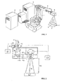
- FIG. 1 this is a schematic view illustrating a laser welding apparatus (i.e., a remote welding system; hereinafter simply referred to as a "system") is constructed in accordance with teachings of the invention.
- the system shown in FIG. 1 is configured to weld a work piece when it is distantly positioned away therefrom by using a laser without directly contacting a welding jig with the work piece. This is clearly different from conventional spot welding, etc., and is referred to as remote welding.
- the system generally comprises a robot 1 and a robot controller 2 for controlling the robot 1.
- a scanner head 6 i.e., laser irradiating device
- an optical fiber cable 5 i.e., light guiding device; hereinafter simply referred to as an "optical fiber"
- a control unit 4 controls the scanner head 6 and the laser oscillator 3.
- the control unit 4 is a computer that has, for example, a central processing unit, a memory unit, etc.
- control unit 4 and other control units described herein can consist of a microcomputer including a central processing unit (CPU), input and output ports (I/O), random access memory (RAM), keep alive memory (KAM), a common data bus and read only memory (ROM) as an electronic storage medium for executable programs and certain stored values as discussed hereinafter.
- the functions could be, for example, implemented in software as the executable programs, or could be implemented in whole or in part by separate hardware in the form of one or more integrated circuits (IC).
- IC integrated circuits
- a YAG laser oscillator is used to guide the laser beam through the optical fiber cable 5 by example.
- the robot 1 is a general multi-axis robot (also known as a multi-articulated robot, etc.).
- the robot 1 can change the position of its arm and allows the tip of the arm (i.e., scanner head 6) to move in various directions according to the data of a motion path provided by an instruction.
- a moving range of laser irradiation is indicated by reference numeral 7.
- FIG. 2 is a diagram illustrating an inner part of the scanner head 6.
- the inner part of the scanner head 6 comprises an optical fiber 5, an optical fiber retaining portion 12 for retaining the optical fiber, a fiber position changing mechanism 13 and a fiber actuator control unit 14.
- the inner part of the scanner head 6 also includes a collimate lens 16, a fixed mirror 17, a condensing distance varying lens 119, a first lens 110, a second lens 111, a condensing distance varying lens actuator 112, a laser scanning mirror 113 (i.e., reflecting device or reflecting mirror), a mirror actuator 114 and a mirror control unit 115.
- a laser beam is indicated by reference numeral 15.
- the laser beam 15 passes through the collimate lens 16 to the fixed lens 17, then passes through the condensing distance varying lens 119, the first lens 110 and the second condensing lens 111.
- the laser beam 15 is then reflected and emitted by the laser scanning mirror 113.
- the laser scanning mirror 113 rotatably moves via the mirror actuator 114.
- the mirror control unit 115 operates the mirror actuator 114 based on pre-instructed focus speed data.
- the mirror control unit 115 calculates a rotating angular velocity of the laser scanning mirror 113 to obtain a focus speed from the focus speed data. Further, the mirror control unit 115 controls the laser scanning mirror 113 such that the focus speed becomes an instructed (or commanded) focus speed.
- the laser welding apparatus it is possible to irradiate the laser in various directions through motion of a robot comprising the scanner head 6 as well as through motion of the laser scanning mirror 113.
- the fiber actuator control unit 14 controls the fiber position changing mechanism 13 depending on a distance 116 from the scanner head 6 to a work piece 117 in a welding path.
- the fiber actuator control unit 14 then changes a position of a laser emitting end 61 of the optical fiber 5 to adjust a focus position of the laser beam in the welding path.
- the fiber position changing mechanism 13 is fixed in position during a welding operation. However, a laser irradiating distance 116 from the scanner head 6 to the work piece 117 may be substantially changed due to the change in an installing position of the laser welding apparatus or the work piece. In such a case, the fiber position changing mechanism 13 can be adjusted to perform a laser focus adjustment.
- a laser irradiating range by the scanner head 6 becomes a three-dimensional range as indicated by the reference numeral 7 in FIG. 1. That is, a position in the X-Y directions thereof can be changed by the laser scanning mirror 113. Further, a position in the Z direction can be changed by a position change of the condensing distance varying lens 119.
- a moving speed (welding point speed) of a welding point of the laser beam irradiated to the work piece becomes a resultant speed of a focus moving speed of the laser beam through movement of the scanner head 6 by motion of the robot 1 and a focus moving speed of the laser beam by a rotation of the laser scanning mirror 113.
- the focus of the laser beam is changed by moving the scanner head 6 while rotating the laser scanning mirror 113.
- the moving speed of the welding point position of the laser beam irradiated to the work piece becomes a resultant speed of the focus moving speed of the laser beam by the movement of the scanner head 6 and the focus moving speed of the laser beam by the rotation of the laser scanning mirror 113 itself.
- a robot speed may be changed at a test-run in the course of preparing for manufacture.
- a welding point speed at this time can become identical to a conventional welding point speed of the robot at a manufacturing site, then there would be no changes in the welding state.
- the robot controller 2 stores an instructional data in advance and performs a welding operation by operating each axis of the robot 1 according to the instructional data.
- the instructional data includes a motion path of the robot during the welding operation (i.e., a path for moving the scanner head 6), an operating speed of the robot while proceeding in the motion path, a focus moving speed of the laser beam corresponding to the motion path or operating speed of the robot, a rotating speed of the laser scanning mirror 113 for obtaining the focus moving speed, a position data of the condensing distance varying lens 119 for changing a focus corresponding to the laser irradiating position, welding conditions, etc.
- a motion path of the robot during the welding operation i.e., a path for moving the scanner head 6
- an operating speed of the robot while proceeding in the motion path a focus moving speed of the laser beam corresponding to the motion path or operating speed of the robot
- a rotating speed of the laser scanning mirror 113 for obtaining the focus moving speed
- a position data of the condensing distance varying lens 119 for changing a focus corresponding to the laser irradiating position, welding conditions, etc.
- the stored robot speed and the rotating speed of the laser scanning mirror 113 correspond to a speed when operating the robot at a manufacturing site. Further, the position data of the condensing distance varying lens 119 for changing the focus corresponding to the laser irradiating position corresponds to a motion path of the robot 1 and a rotating angle of the laser scanning mirror 113. As such, irrespective of the robot speed or the focus speed, the condensing distance varying lens 119 is instructed to be changed according to a current position of the robot 1 and a current rotating angle of the laser scanning mirror 113.
- the current position of the robot 1 and the current rotating angle of the laser scanning mirror 113 are obtained from a value of an encoder disposed therein.
- the position data of the condensing distance varying lens 119 may correspond to the motion path of the robot 1 and the rotating angle of the laser scanning mirror 113.
- the welding conditions include a welding point speed, a laser power, a laser irradiating start position and a laser irradiating finish position.
- the welding point speed is a resultant speed of the focus moving speed by a movement of the scanner head 6 and a focus moving speed of the laser beam by a rotation of the scanning mirror 113.
- the laser irradiating start position and the laser irradiating finish position correspond to a current position obtained from an encoder (not shown) of each axis of the robot 1 and a current rotating angle of the laser scanning mirror 113 obtained from an encoder (not shown) of the mirror actuator 114.
- the laser irradiating position can be calculated in real time. A laser irradiation starts when reaching the laser irradiating start point and the laser irradiation finishes when reaching the laser irradiating finish point.
- the mirror control unit 115 of the control unit 4 controls a rotating speed of the laser scanning mirror 113 within the scanner 6 and the laser power value at the time of an override of the robot operation (that is, changing a moving speed of the scanner head 6).
- an operating speed of the robot may become slower in an instruction playback operation than an actual operation.
- the control unit 4 instructs the rotating speed of the laser scanning mirror 113 and the laser power value of the laser oscillator 3 to the scanner head 6 and the laser oscillator 3, respectively, depending on the override ratio (a moving speed change ratio).
- the override ratio is set at 100% when the robot is actually operated. That is, a robot speed stored in the robot controller 2 has 100% of the override ratio.
- the robot controller 2 can be generally operated depending on various robot speeds by changing the override ratio. For example, when the override ratio is 50%, the robot controller 2 operates at a speed that is half of the robot speed in an actual operation.
- the control unit 4 obtains an override ratio instructed in the robot controller 2.
- the control unit 4 then instructs a rotating speed of the laser scanning mirror 113 and a laser power value of the laser oscillator 3 to the scanner head 6 and the laser oscillator 3, respectively, depending on the obtained override ratio.
- FIG. 3 is a flow chart illustrating processing sequences at the time of an override operation (e.g., when a robot speed is set to be slow).
- the control unit 4 estimates a robot speed at the time of an override operation from a robot speed among the instructional data and the instructed override ratio at step S1.
- the instructional data is obtained from the robot controller 2, and an operator can input the override ratio into the robot controller 2.
- control unit 4 subtracts the robot speed at the time of an override operation estimated in step S1 from the welding point speed in the welding conditions of the instructional data.
- This step S2 calculates a rotating speed of the laser scanning mirror 113 at the time of the override operation.
- the control unit 4 receives an initiating instruction of the override operation and instructs the robot controller 2 to rotate the laser scanning mirror 113 at the calculated rotating speed in step S3.
- this motion is only an example. In other configurations, movement other than rotation of the laser scanning mirror 113 is possible.
- the robot controller 2 receives such an instruction and determines whether the laser scanning mirror 113 can be rotated at such a rotating speed at step S4. This process is explained below in detail.
- step S4 If the mirror can be rotated in a rotating operation by an instruction in response to the query of step S4 (i.e., the answer to step S4 is Yes), then the robot controller 2 performs an override operation by an instructed override ratio while rotating the laser scanning mirror 113 at a rotating speed by an instruction from the control unit 4 at step S10.
- the welding point speed becomes a speed at an actual operation (i.e., predetermined speed), wherein the welding speed is a resultant speed of the focus moving speed of the laser beam by a movement of the robot (a scanner head) and the focus moving speed of the laser beam by a rotation of the laser scanning mirror.
- the laser irradiating position is calculated in real time. Also, laser irradiation starts when reaching the laser irradiating start point, and laser irradiation finishes when reaching the laser irradiating finish point during the override operation.
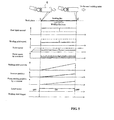
- FIGS. 4 and 5 illustrate the functions of this embodiment.
- FIG. 4 shows a time chart when an override operation is performed in accordance with this embodiment.
- FIG. 5 is a time chart when a conventional override operation is performed as a comparative example. In these time charts, the abscissa axis in each drawing indicates the time.
- the robot speed is decreased (solid line in the drawings) if operated by an override instruction.
- the focus moving speed by a rotation of the scanner increases.
- the welding point speed which is a resultant speed of the focus moving speed by movement of the scanner head 6 and the focus moving speed by rotation of the laser scanning mirror 113, does not differ from that when the override ratio is 100%. Further, the heat input amount thereof does not change.
- the robot speed is decreased (solid line in the drawings) if operated by an override instruction.
- the focus moving speed by the scanner is also decreased by the override instruction.
- the welding point speed which is a resultant speed of the robot moving speed and the focus moving speed by rotation of the laser scanning mirror, becomes slower than that when the override ratio is 100% (changed from the dash line position to the solid line position in the drawings). If so, since the welding point speed slows down, a heat input amount at this time becomes higher than that in an actual operation (changed from the dash line position to the solid line position in the drawings).
- step S4 it is decided whether or not the laser scanning mirror 113 can be rotated at a rotating speed through an instruction.
- Such a step makes the welding point speed to be identical as in an actual operation by increasing the rotating speed of the laser scanning mirror 113.
- a heat input amount cannot become the same only by increasing the rotating speed of the laser scanning mirror 113 depending on the input override ratio.
- step S4 whether or not the laser scanning mirror 113 is rotatable in step S4 is determined by considering whether or not an instructed rotating speed of the laser scanning mirror 113 exceeds a maximum of the rotating speed.
- a resultant speed of the focus moving speed of the laser beam by a robot movement and the focus position moving speed of the laser beam by a movement of the laser scanning mirror 113 is equal to or less than a predetermined lower limit speed, and the rotating speed of the laser scanning mirror 113 is controlled.
- a laser power value of the laser oscillator 3 is also further adjusted as described in next step S5.
- a signal for transmitting a negative response is delivered from the robot controller 2 to the control unit 4.
- adjusting the laser power value data on an output suitable for the welding point speed is prepared in advance. Then, such data is used in the control unit 4. Also, the control unit 4 determines whether the adjusted laser power value is equal to or greater than a predetermined critical value in step S6 as explained below). Then, when the adjusted laser power value is equal to or greater than a predetermined critical value, the laser power value is instructed to the laser oscillator. Further, the robot controller 2 is instructed to perform an override operation by an instructed override ratio in step S7.
- FIG. 6 is a graph showing a laser power value that causes a welding point speed change to be the same as a heat input amount during an actual operation. From the graph shown in FIG. 6, when a laser power value in a heat input amount at an actual operation is a standard power, a laser power value for causing the heat input amount to be the same as the heat input amount at an actual operation can be obtained by decreasing a welding point speed.
- FIG. 6 shows three different welding conditions by way of examples.
- a table corresponding to the laser power value for the welding point as in the above graph is stored in the control unit 4.
- the rotating speed may not reach a predetermined speed (a welding point speed at an actual operation) even if the control unit 4 increases a rotating speed of the laser scanning mirror 113 depending on the override ratio.
- the control unit 4 further adjusts a laser power value to become a heat input amount necessary for the welding point speed with reference to the corresponding table as shown in the graph of FIG. 7.
- step S6 it is determined whether an adjusted laser power value is equal to or greater than a predetermined critical value. This is because if a laser power value is excessively small, there is a concern that no matter how slow the welding point speed is the laser power would be lacking for performing suitable welding.
- control unit 4 when the laser power is incapable of welding and is additionally decreased (i.e., the response to the query of step S6 is No), the control unit 4 further adjusts an instructed override ratio in step S11.
- FIG. 7 is a graph showing a laser power value related to a welding speed that explains an override ratio change. As shown in FIG. 7, for example, when the override ratio is low (e.g., 10%), the laser power value is accordingly decreased. However, since such laser power is incapable of welding, the instructed override ratio is increased up to 50%. Further, such an instruction is transmitted from the control unit 4 to the robot controller 2.
- the override ratio e.g. 10%
- a laser power that is incapable of welding is set as a critical value in advance.
- the control unit 4 may decrease the laser power value according to the welding point speed as above. In this case, if such a value is less than the critical value, then the control unit changes the override ratio to be equal to or greater than the critical value and instructs it to the robot controller 2. As such, without decreasing the laser power than what is absolutely necessary, a welding state that is the same as an actual operation can be obtained.
- a focus moving speed by the laser scanning mirror 113 at the time of an override is calculated for throughout the entire motion path to be overridden.
- it can be calculated in real time from a robot speed during an override operation.
- a motion path is shown as a straight line in the drawings illustrating the embodiments, the path is not limited to the straight line. Alternatively, the motion path may be applied to various configurations such as an arc.
- an irradiating direction of the laser beam can be changed by using a prism instead of the reflecting mirror.
- the invention can be used for laser welding and manufacturing, for example.
Landscapes
- Physics & Mathematics (AREA)
- Optics & Photonics (AREA)
- Engineering & Computer Science (AREA)
- Plasma & Fusion (AREA)
- Mechanical Engineering (AREA)
- Robotics (AREA)
- Laser Beam Processing (AREA)
- Manipulator (AREA)
Abstract
Description
- The present invention relates generally to laser welding and particularly, but not exclusively, to an apparatus and method for performing laser welding operations.
- Laser welding is currently used to carry out robotic welding.
Japanese Laid-Open Patent Publication No. 2005-177862 - In the remote welding technique disclosed in
Japanese Laid Open Patent Publication No. 2005-177862 - That is, during the test-run, the moving speed of the laser irradiating device at the tip of the arm is set to be slower than that of the actual operation to check whether the laser irradiating device is properly operated without interfering with other robotic arms or peripheral devices. As such, for example, a moving speed of a point where a laser is irradiated (welding point speed) is slower during the test-run that that of the actual operation. Thus, energy is excessively applied at the welding point (oversupply of heat input amount) during the test-run. As a result, there is a problem in that a welding state for the actual operation cannot be accurately determined during the test-run.
- It is an aim of the invention to address this issue and to improve upon known technology. In embodiments of the invention, laser welding operations may be performed to reproduce a welding state substantially identical to the actual operation of a robot at a manufacturing site. This may be achieved even when an operating speed of the robot is changed during a test-run in the course of preparing for manufacture. Other aims and advantages of the invention will become apparent from the following description, claims and drawings.
- Aspects of the invention therefore provide an apparatus and a method as claimed in the appended claims.
- According to another aspect of the invention there is provided a laser welding apparatus for performing welding by irradiating a laser beam, the apparatus comprising a laser oscillator operable to generate a laser beam, a laser irradiating device having a reflecting device configured to change an irradiating direction of the laser beam guided from the laser oscillator, a moving device operable to move the laser irradiating device and a control unit operable to control the reflecting device such that when an operating speed of the moving device is changed, a resultant speed of a focus moving speed of the laser beam by movement of the laser irradiating device and a focus moving speed of the laser beam by movement of the reflecting device is equal to a predetermined value.
- In an embodiment, the reflecting device is a reflecting mirror.
- In an embodiment, the control unit is arranged to change a laser power value of the laser oscillator when the resultant speed becomes less than or equal to a predetermined lower limit speed.
- In an embodiment, the control unit is operable to change the laser power value of the laser operator by reducing the laser power value of the laser oscillator as the resultant speed slows down.
- In an embodiment, the control unit is operable to increase a moving speed of the moving device when a projected laser power value is less than a predetermined lower limit.
- In an embodiment, the reflecting device is configured to rotate to change the irradiating direction of the laser beam guided from the laser oscillator.
- According to a further aspect of the invention there is provided a laser welding apparatus for performing welding by irradiating a laser beam, the apparatus comprising a laser oscillator operable to generate a laser beam, a laser irradiating device having a reflecting device configured to change an irradiating direction of the laser beam guided from the laser oscillator, a moving device operable to move the laser irradiating device and a control unit operable to control the reflecting device such that when an operating speed of the moving device is changed, a moving speed of a laser focus based on movement of the laser irradiating device and movement of the reflecting device is equal to a predetermined value.
- According to a still further aspect of the invention there is provided an apparatus for laser welding, comprising a laser oscillator for generating a laser beam, a laser irradiating device having a directing device to direct the laser beam at a weld point at a first welding speed, a moving device operable to move the laser irradiating device, the moving device operable to move the weld point at a second welding speed and a control unit operable to selectively move at least one of the directing device and the head moving device to maintain a resultant speed of the first welding speed and the second welding speed equal to a predetermined value.
- According to another aspect of the invention there is provided a method of performing laser welding using a laser irradiating device having a reflecting mirror movable to change an irradiating direction of a laser beam, the method comprising generating a laser beam, moving the laser irradiating device at an operating speed other than a programmed operating speed and controlling the reflecting mirror such that a resultant speed of a focus moving speed of the laser beam by movement of the laser irradiating device and a focus moving speed of the laser beam by movement of the reflecting mirror is equal to a predetermined resultant speed when the laser irradiating device is operated at the programmed operating speed.
- The method may comprise changing a laser power value of the laser beam when the resultant speed becomes equal to or less than a predetermined lower limit speed.
- The method may comprise increasing the operating speed when the laser power value becomes equal to or lower than a predetermined lower limit according to the change of the laser power value.
- Controlling the reflecting mirror may include calculating a rotating angular velocity of the reflecting mirror to obtain the focus moving speed using the predetermined resultant speed.
- The method may comprise changing a distance of the laser irradiating device relative to a weld point by changing a position of a condensing distance varying lens located in the laser irradiating device.
- In an embodiment, the method comprises corresponding position data of the condensing distance varying lens to a motion path of the moving device and a rotating angle of the reflecting mirror.
- The method may comprise starting a laser irradiation at a laser irradiating start point and terminating the laser irradiation when reaching a laser irradiating finish point.
- In an embodiment, the method comprises instructing a rotating speed of the reflecting mirror and the laser power of the laser oscillator depending on an override ratio.
- The method may comprise obtaining the override ratio from external of the laser irradiating device.
- The method may comprise determining whether the reflecting mirror can be rotated at the rotating speed.
- In an embodiment, the method comprises adjusting the laser power value if the rotating speed exceeds a rotatable maximum speed of the reflecting mirror.
- In an embodiment, the method comprises determining whether the adjusted laser power value is less than a predetermined critical value.
- The method may comprise changing the override ratio to be equal to or greater than the predetermined critical value if the adjusted laser power value is less than the predetermined critical value.
- The method may comprise performing an override operation with an adjusted laser power value if the adjusted power value is greater than or equal to the predetermined critical value.
- For example, an apparatus and method for performing laser welding operations comprises a laser oscillator operable to generate a laser beam, a laser irradiating device having a reflecting device configured to change an irradiating direction of the laser beam guided from the laser oscillator, a moving device operable to move the laser irradiating device and a control unit. The control unit is operable to control the reflecting device such that when an operating speed of the moving device is changed, a resultant speed of a focus moving speed of the laser beam by movement of the laser irradiating device and a focus moving speed of the laser beam by movement of the reflecting device is equal to a predetermined value.
- According to another example of such a laser welding apparatus, the apparatus comprises a laser oscillator operable to generate a laser beam, a laser irradiating device having a reflecting device configured to change an irradiating direction of the laser beam guided from the laser oscillator, a moving device operable to move the laser irradiating device and a control unit. The control unit is operable to control the reflecting device such that when an operating speed of the moving device is changed, a moving speed of a laser focus based on movement of the laser irradiating device and of the reflecting device is equal to a predetermined value.
- Another apparatus for laser welding taught herein comprises a laser oscillator for generating a laser beam, a laser irradiating device having a directing device to direct the laser beam at a weld point at a first welding speed, a moving device operable to move the laser irradiating device, the moving device operable to move the weld point at a second welding speed, and a control unit. The control unit is operable to selectively move at least one of the directing device and the head moving device to maintain a resultant speed of the first welding speed and the second welding speed equal to a predetermined value.
- Methods of method of performing laser welding using a laser irradiating device having a reflecting mirror movable to change an irradiating direction of a laser beam are also taught herein. One such method comprises generating a laser beam, moving the laser irradiating device at an operating speed other than a programmed operating speed and controlling the reflecting mirror such that a resultant speed of a focus moving speed of the laser beam by movement of the laser irradiating device and a focus moving speed of the laser beam by movement of the reflecting mirror is equal to a predetermined resultant speed when the laser irradiating device is operated at the programmed operating speed.
- Within the scope of this application it is envisaged that the various aspects, embodiments, examples, features and alternatives set out in the preceding paragraphs, in the claims and/or in the following description may be taken individually or in any combination thereof.
- The present invention will now be described, by way of example only, with reference to the accompanying drawings in which:
- FIG. 1 is a schematic view illustrating a laser welding apparatus;
- FIG. 2 is a diagram illustrating an inner part of a scanner head;
- FIG. 3 is a flow chart illustrating processing sequences during an override operation (i.e., when a robot speed becomes slower);
- FIG. 4 is a time chart illustrating when an override operation is performed in accordance with embodiments of the invention;
- FIG. 5 is a time chart illustrating when a conventional override operation is performed as a comparative example;
- FIG. 6 is a graph showing a laser power value causing a welding point speed change to be the same as a heat input amount during an actual operation; and
- FIG. 7 is a graph showing a laser power value relating to a welding speed for explaining an override ratio change.
- Referring firstly to FIG. 1, this is a schematic view illustrating a laser welding apparatus (i.e., a remote welding system; hereinafter simply referred to as a "system") is constructed in accordance with teachings of the invention. The system shown in FIG. 1 is configured to weld a work piece when it is distantly positioned away therefrom by using a laser without directly contacting a welding jig with the work piece. This is clearly different from conventional spot welding, etc., and is referred to as remote welding.
- The system generally comprises a
robot 1 and arobot controller 2 for controlling therobot 1. A scanner head 6 (i.e., laser irradiating device) irradiates a laser beam disposed at a tip of an arm of therobot 1, and an optical fiber cable 5 (i.e., light guiding device; hereinafter simply referred to as an "optical fiber") guides a laser beam from a laser oscillator 3 (a laser beam source) to thescanner head 6. - A control unit 4 controls the
scanner head 6 and thelaser oscillator 3. - The control unit 4 is a computer that has, for example, a central processing unit, a memory unit, etc. For example, control unit 4 and other control units described herein can consist of a microcomputer including a central processing unit (CPU), input and output ports (I/O), random access memory (RAM), keep alive memory (KAM), a common data bus and read only memory (ROM) as an electronic storage medium for executable programs and certain stored values as discussed hereinafter. The functions could be, for example, implemented in software as the executable programs, or could be implemented in whole or in part by separate hardware in the form of one or more integrated circuits (IC).
- As for the
laser oscillator 3, a YAG laser oscillator is used to guide the laser beam through theoptical fiber cable 5 by example. - The
robot 1 is a general multi-axis robot (also known as a multi-articulated robot, etc.). Therobot 1 can change the position of its arm and allows the tip of the arm (i.e., scanner head 6) to move in various directions according to the data of a motion path provided by an instruction. A moving range of laser irradiation is indicated byreference numeral 7. - FIG. 2 is a diagram illustrating an inner part of the
scanner head 6. As shown in FIG. 2, the inner part of thescanner head 6 comprises anoptical fiber 5, an opticalfiber retaining portion 12 for retaining the optical fiber, a fiberposition changing mechanism 13 and a fiberactuator control unit 14. The inner part of thescanner head 6 also includes acollimate lens 16, a fixedmirror 17, a condensingdistance varying lens 119, afirst lens 110, a second lens 111, a condensing distance varyinglens actuator 112, a laser scanning mirror 113 (i.e., reflecting device or reflecting mirror), amirror actuator 114 and amirror control unit 115. - A laser beam is indicated by
reference numeral 15. Thelaser beam 15 passes through thecollimate lens 16 to the fixedlens 17, then passes through the condensingdistance varying lens 119, thefirst lens 110 and the second condensing lens 111. Thelaser beam 15 is then reflected and emitted by thelaser scanning mirror 113. - The
laser scanning mirror 113 rotatably moves via themirror actuator 114. Themirror control unit 115 operates themirror actuator 114 based on pre-instructed focus speed data. Themirror control unit 115 calculates a rotating angular velocity of thelaser scanning mirror 113 to obtain a focus speed from the focus speed data. Further, themirror control unit 115 controls thelaser scanning mirror 113 such that the focus speed becomes an instructed (or commanded) focus speed. - As such, in the laser welding apparatus, it is possible to irradiate the laser in various directions through motion of a robot comprising the
scanner head 6 as well as through motion of thelaser scanning mirror 113. - Further, the fiber
actuator control unit 14 controls the fiberposition changing mechanism 13 depending on adistance 116 from thescanner head 6 to awork piece 117 in a welding path. The fiberactuator control unit 14 then changes a position of alaser emitting end 61 of theoptical fiber 5 to adjust a focus position of the laser beam in the welding path. The fiberposition changing mechanism 13 is fixed in position during a welding operation. However, alaser irradiating distance 116 from thescanner head 6 to thework piece 117 may be substantially changed due to the change in an installing position of the laser welding apparatus or the work piece. In such a case, the fiberposition changing mechanism 13 can be adjusted to perform a laser focus adjustment. - A laser irradiating range by the
scanner head 6 becomes a three-dimensional range as indicated by thereference numeral 7 in FIG. 1. That is, a position in the X-Y directions thereof can be changed by thelaser scanning mirror 113. Further, a position in the Z direction can be changed by a position change of the condensingdistance varying lens 119. - In laser welding, a moving speed (welding point speed) of a welding point of the laser beam irradiated to the work piece becomes a resultant speed of a focus moving speed of the laser beam through movement of the
scanner head 6 by motion of therobot 1 and a focus moving speed of the laser beam by a rotation of thelaser scanning mirror 113. In other words, the focus of the laser beam is changed by moving thescanner head 6 while rotating thelaser scanning mirror 113. Thus, the moving speed of the welding point position of the laser beam irradiated to the work piece becomes a resultant speed of the focus moving speed of the laser beam by the movement of thescanner head 6 and the focus moving speed of the laser beam by the rotation of thelaser scanning mirror 113 itself. - As mentioned above, a robot speed may be changed at a test-run in the course of preparing for manufacture. Thus, if a welding point speed at this time can become identical to a conventional welding point speed of the robot at a manufacturing site, then there would be no changes in the welding state.
- The
robot controller 2 stores an instructional data in advance and performs a welding operation by operating each axis of therobot 1 according to the instructional data. - The instructional data, for example, includes a motion path of the robot during the welding operation (i.e., a path for moving the scanner head 6), an operating speed of the robot while proceeding in the motion path, a focus moving speed of the laser beam corresponding to the motion path or operating speed of the robot, a rotating speed of the
laser scanning mirror 113 for obtaining the focus moving speed, a position data of the condensingdistance varying lens 119 for changing a focus corresponding to the laser irradiating position, welding conditions, etc. - The stored robot speed and the rotating speed of the
laser scanning mirror 113 correspond to a speed when operating the robot at a manufacturing site. Further, the position data of the condensingdistance varying lens 119 for changing the focus corresponding to the laser irradiating position corresponds to a motion path of therobot 1 and a rotating angle of thelaser scanning mirror 113. As such, irrespective of the robot speed or the focus speed, the condensingdistance varying lens 119 is instructed to be changed according to a current position of therobot 1 and a current rotating angle of thelaser scanning mirror 113. - Further, the current position of the
robot 1 and the current rotating angle of thelaser scanning mirror 113 are obtained from a value of an encoder disposed therein. Also, in this embodiment, the position data of the condensingdistance varying lens 119 may correspond to the motion path of therobot 1 and the rotating angle of thelaser scanning mirror 113. However, when using a lens having an auto-focusing function, it is not necessary to correspond as mentioned above. Rather, it is possible to focus while measuring a distance between thescanner head 6 and thework piece 117 in a non-contact manner. Since auto-focusing is well known in conventional camera techniques, etc., its detailed description is omitted herein. - Also, the welding conditions include a welding point speed, a laser power, a laser irradiating start position and a laser irradiating finish position. The welding point speed is a resultant speed of the focus moving speed by a movement of the
scanner head 6 and a focus moving speed of the laser beam by a rotation of thescanning mirror 113. The laser irradiating start position and the laser irradiating finish position correspond to a current position obtained from an encoder (not shown) of each axis of therobot 1 and a current rotating angle of thelaser scanning mirror 113 obtained from an encoder (not shown) of themirror actuator 114. As such, the laser irradiating position can be calculated in real time. A laser irradiation starts when reaching the laser irradiating start point and the laser irradiation finishes when reaching the laser irradiating finish point. - The
mirror control unit 115 of the control unit 4 controls a rotating speed of thelaser scanning mirror 113 within thescanner 6 and the laser power value at the time of an override of the robot operation (that is, changing a moving speed of the scanner head 6). - For example, an operating speed of the robot may become slower in an instruction playback operation than an actual operation. In such a case, the control unit 4 instructs the rotating speed of the
laser scanning mirror 113 and the laser power value of thelaser oscillator 3 to thescanner head 6 and thelaser oscillator 3, respectively, depending on the override ratio (a moving speed change ratio). - The override ratio is set at 100% when the robot is actually operated. That is, a robot speed stored in the
robot controller 2 has 100% of the override ratio. Here, therobot controller 2 can be generally operated depending on various robot speeds by changing the override ratio. For example, when the override ratio is 50%, therobot controller 2 operates at a speed that is half of the robot speed in an actual operation. - The control unit 4 obtains an override ratio instructed in the
robot controller 2. The control unit 4 then instructs a rotating speed of thelaser scanning mirror 113 and a laser power value of thelaser oscillator 3 to thescanner head 6 and thelaser oscillator 3, respectively, depending on the obtained override ratio. - FIG. 3 is a flow chart illustrating processing sequences at the time of an override operation (e.g., when a robot speed is set to be slow). First, the control unit 4 estimates a robot speed at the time of an override operation from a robot speed among the instructional data and the instructed override ratio at step S1. The instructional data is obtained from the
robot controller 2, and an operator can input the override ratio into therobot controller 2. - Next, the control unit 4 subtracts the robot speed at the time of an override operation estimated in step S1 from the welding point speed in the welding conditions of the instructional data. This step S2 calculates a rotating speed of the
laser scanning mirror 113 at the time of the override operation. - The control unit 4 receives an initiating instruction of the override operation and instructs the
robot controller 2 to rotate thelaser scanning mirror 113 at the calculated rotating speed in step S3. Of course, this motion is only an example. In other configurations, movement other than rotation of thelaser scanning mirror 113 is possible. Therobot controller 2 receives such an instruction and determines whether thelaser scanning mirror 113 can be rotated at such a rotating speed at step S4. This process is explained below in detail. - If the mirror can be rotated in a rotating operation by an instruction in response to the query of step S4 (i.e., the answer to step S4 is Yes), then the
robot controller 2 performs an override operation by an instructed override ratio while rotating thelaser scanning mirror 113 at a rotating speed by an instruction from the control unit 4 at step S10. - As such, the welding point speed becomes a speed at an actual operation (i.e., predetermined speed), wherein the welding speed is a resultant speed of the focus moving speed of the laser beam by a movement of the robot (a scanner head) and the focus moving speed of the laser beam by a rotation of the laser scanning mirror.
- Further, as in an actual operation, the laser irradiating position is calculated in real time. Also, laser irradiation starts when reaching the laser irradiating start point, and laser irradiation finishes when reaching the laser irradiating finish point during the override operation.
- FIGS. 4 and 5 illustrate the functions of this embodiment. FIG. 4 shows a time chart when an override operation is performed in accordance with this embodiment. FIG. 5 is a time chart when a conventional override operation is performed as a comparative example. In these time charts, the abscissa axis in each drawing indicates the time.
- As shown in FIG. 4, in this embodiment, when the override ratio is 100% (dash line in the drawings), the robot speed is decreased (solid line in the drawings) if operated by an override instruction. However, according to the above, the focus moving speed by a rotation of the scanner increases. To this end, the welding point speed, which is a resultant speed of the focus moving speed by movement of the
scanner head 6 and the focus moving speed by rotation of thelaser scanning mirror 113, does not differ from that when the override ratio is 100%. Further, the heat input amount thereof does not change. - Therefore, by adopting this embodiment, a welding state that is the same as in an actual operation can be obtained, despite an override. By performing an override operation to slow down an operation of the
robot 1, it can be determined whether there is a problem in the operation and whether the robot interferes with other objects. - Meanwhile, in a conventional method as shown in FIG. 5, when the override ratio is 100% (dash line in the drawings), the robot speed is decreased (solid line in the drawings) if operated by an override instruction. At this time, the focus moving speed by the scanner is also decreased by the override instruction. To this end, the welding point speed, which is a resultant speed of the robot moving speed and the focus moving speed by rotation of the laser scanning mirror, becomes slower than that when the override ratio is 100% (changed from the dash line position to the solid line position in the drawings). If so, since the welding point speed slows down, a heat input amount at this time becomes higher than that in an actual operation (changed from the dash line position to the solid line position in the drawings).
- Therefore, when the robot slows down during an override as in the conventional method, more heat is required than in an actual operation such that a welding state becomes different from that in the actual operation. Although a movement of the robot can be checked, a welding state corresponding to such a movement cannot be checked.
- Next, an adjustment of the laser power is explained. In step S4 discussed above, it is decided whether or not the
laser scanning mirror 113 can be rotated at a rotating speed through an instruction. Such a step makes the welding point speed to be identical as in an actual operation by increasing the rotating speed of thelaser scanning mirror 113. However, a heat input amount cannot become the same only by increasing the rotating speed of thelaser scanning mirror 113 depending on the input override ratio. - For example, when an override ratio is small, a welding point speed does not reach a speed in an actual operation, despite rotating the
laser scanning mirror 113 at a maximum speed. To this end, whether or not thelaser scanning mirror 113 is rotatable in step S4 is determined by considering whether or not an instructed rotating speed of thelaser scanning mirror 113 exceeds a maximum of the rotating speed. - Also, when the rotating speed exceeds a rotatable maximum speed of the laser scanning mirror 113 (i.e., the response to step S4 is No) this means that a resultant speed of the focus moving speed of the laser beam by a robot movement and the focus position moving speed of the laser beam by a movement of the
laser scanning mirror 113 is equal to or less than a predetermined lower limit speed, and the rotating speed of thelaser scanning mirror 113 is controlled. In addition, a laser power value of thelaser oscillator 3 is also further adjusted as described in next step S5. Moreover, in case of a "No" response in step S4, a signal for transmitting a negative response is delivered from therobot controller 2 to the control unit 4. - As for adjusting the laser power value, data on an output suitable for the welding point speed is prepared in advance. Then, such data is used in the control unit 4. Also, the control unit 4 determines whether the adjusted laser power value is equal to or greater than a predetermined critical value in step S6 as explained below). Then, when the adjusted laser power value is equal to or greater than a predetermined critical value, the laser power value is instructed to the laser oscillator. Further, the
robot controller 2 is instructed to perform an override operation by an instructed override ratio in step S7. - FIG. 6 is a graph showing a laser power value that causes a welding point speed change to be the same as a heat input amount during an actual operation. From the graph shown in FIG. 6, when a laser power value in a heat input amount at an actual operation is a standard power, a laser power value for causing the heat input amount to be the same as the heat input amount at an actual operation can be obtained by decreasing a welding point speed.
- Further, FIG. 6 shows three different welding conditions by way of examples. A table corresponding to the laser power value for the welding point as in the above graph is stored in the control unit 4. The rotating speed may not reach a predetermined speed (a welding point speed at an actual operation) even if the control unit 4 increases a rotating speed of the
laser scanning mirror 113 depending on the override ratio. In such a case, the control unit 4 further adjusts a laser power value to become a heat input amount necessary for the welding point speed with reference to the corresponding table as shown in the graph of FIG. 7. - As such, even if an override ratio is small, a heat input amount equal to that of an actual operation can be maintained. To this end, it is possible to check whether a welding state is the same as that of an actual operation. It is also possible to check an operation of the robot itself by a slow movement.
- Next, the changes of the override ratio will be further explained. In step S6 as discussed above, it is determined whether an adjusted laser power value is equal to or greater than a predetermined critical value. This is because if a laser power value is excessively small, there is a concern that no matter how slow the welding point speed is the laser power would be lacking for performing suitable welding.
- Thus, according to a described embodiment, when the laser power is incapable of welding and is additionally decreased (i.e., the response to the query of step S6 is No), the control unit 4 further adjusts an instructed override ratio in step S11.
- FIG. 7 is a graph showing a laser power value related to a welding speed that explains an override ratio change. As shown in FIG. 7, for example, when the override ratio is low (e.g., 10%), the laser power value is accordingly decreased. However, since such laser power is incapable of welding, the instructed override ratio is increased up to 50%. Further, such an instruction is transmitted from the control unit 4 to the
robot controller 2. - Here, a laser power that is incapable of welding is set as a critical value in advance. The control unit 4 may decrease the laser power value according to the welding point speed as above. In this case, if such a value is less than the critical value, then the control unit changes the override ratio to be equal to or greater than the critical value and instructs it to the
robot controller 2. As such, without decreasing the laser power than what is absolutely necessary, a welding state that is the same as an actual operation can be obtained. - While certain embodiments of the invention are described above, it should be understood that the invention is not limited to those embodiments. For example, herein a focus moving speed by the
laser scanning mirror 113 at the time of an override is calculated for throughout the entire motion path to be overridden. Alternatively, it can be calculated in real time from a robot speed during an override operation. - Further, while a motion path is shown as a straight line in the drawings illustrating the embodiments, the path is not limited to the straight line. Alternatively, the motion path may be applied to various configurations such as an arc.
- Also, an irradiating direction of the laser beam can be changed by using a prism instead of the reflecting mirror.
- The invention can be used for laser welding and manufacturing, for example.
- Accordingly, the above-described embodiments have been described in order to allow easy understanding of the present invention and do not limit the present invention. On the contrary, the invention is intended to cover various modifications and equivalent arrangements included within the scope of the appended claims, which scope is to be accorded the broadest interpretation so as to encompass all such modifications and equivalent structure as is permitted under the law.
- This application claims priority from
Japanese Patent Application Nos. 2006-081560, filed 23rd March 2006 2007-023309, filed 1st February 2007
Claims (12)
- A laser welding apparatus comprising:laser generation means for generating a laser beam;direction changing means having a reflecting device for changing an irradiating direction of the laser beam guided from the laser generation means;means for moving the direction changing means; andcontrol means for controlling the reflecting device such that when an operating speed of the moving means is changed, a moving speed of a laser focus based on movement of the direction changing means and movement of the reflecting device is equal to a predetermined value.
- An apparatus as claimed in claim 1 wherein the control means is arranged to control the reflecting device such that when an operating speed of the moving means is changed, a resultant speed of a focus moving speed of the laser beam by movement of the direction changing means and a focus moving speed of the laser beam by movement of the reflecting device is equal to a predetermined value.
- An apparatus as claimed in claim 1 or claim 2 wherein the control means is arranged to change a laser power value of the laser generation means when the resultant speed becomes less than or equal to a predetermined lower limit speed.
- An apparatus as claimed in claim 3 wherein the control means is arranged to change the laser power value of the laser generation means as the resultant speed decreases.
- An apparatus as claimed in claim 4 wherein the control means is arranged to increase a moving speed of the moving device when a projected laser power value is less than a predetermined lower limit.
- An apparatus as claimed in any preceding claim wherein the reflecting device is configured to rotate to change the irradiating direction of the laser beam guided from the laser generation means.
- A method of performing laser welding using a laser irradiating device having a reflecting mirror movable to change an irradiating direction of a laser beam, the method comprising:generating a laser beam;moving the laser irradiating device at an operating speed other than a programmed operating speed; andcontrolling the reflecting mirror such that a resultant speed of a focus moving speed of the laser beam by movement of the laser irradiating device and a focus moving speed of the laser beam by movement of the reflecting mirror is equal to a predetermined resultant speed when the laser irradiating device is operated at the programmed operating speed.
- A method as claimed in claim 7 wherein controlling the reflecting mirror comprises calculating a rotating angular velocity of the reflecting mirror to obtain the focus moving speed using the predetermined resultant speed.
- A method as claimed in claim 7 or claim 8 comprising changing a distance of the laser irradiating device relative to a weld point by changing a position of a condensing distance varying lens located in the laser irradiating device.
- A method as claimed in any of claims 7 to 9 comprising corresponding position data of the condensing distance varying lens to a motion path of the moving device and a rotating angle of the reflecting mirror.
- A method as claimed in any of claims 7 to 10 comprising starting a laser irradiation at a laser irradiating start point and terminating the laser irradiation when reaching a laser irradiating finish point.
- A method as claimed in any of claims 7 to 11 comprising instructing a rotating speed of the reflecting mirror and the laser power of the laser oscillator depending on an override ratio.
Applications Claiming Priority (2)
| Application Number | Priority Date | Filing Date | Title |
|---|---|---|---|
| JP2006081560 | 2006-03-23 | ||
| JP2007023309A JP5070861B2 (en) | 2006-03-23 | 2007-02-01 | Laser welding apparatus and method |
Publications (1)
| Publication Number | Publication Date |
|---|---|
| EP1837115A1 true EP1837115A1 (en) | 2007-09-26 |
Family
ID=37963893
Family Applications (1)
| Application Number | Title | Priority Date | Filing Date |
|---|---|---|---|
| EP07104620A Withdrawn EP1837115A1 (en) | 2006-03-23 | 2007-03-21 | Laser Welding |
Country Status (5)
| Country | Link |
|---|---|
| US (1) | US8716622B2 (en) |
| EP (1) | EP1837115A1 (en) |
| JP (1) | JP5070861B2 (en) |
| KR (1) | KR100962817B1 (en) |
| CN (1) | CN101269442B (en) |
Families Citing this family (16)
| Publication number | Priority date | Publication date | Assignee | Title |
|---|---|---|---|---|
| US20050169346A1 (en) * | 2004-01-29 | 2005-08-04 | Trw Automotive U.S. Llc | Method for monitoring quality of a transmissive laser weld |
| JP4922584B2 (en) * | 2004-12-10 | 2012-04-25 | 株式会社安川電機 | Robot system |
| JP5316124B2 (en) * | 2009-03-13 | 2013-10-16 | 日産自動車株式会社 | Laser welding equipment |
| KR20140045605A (en) * | 2012-09-11 | 2014-04-17 | 현대자동차주식회사 | Laser welding device and welding method for galvanized steel sheet |
| US9067278B2 (en) | 2013-03-29 | 2015-06-30 | Photon Automation, Inc. | Pulse spread laser |
| US9228609B2 (en) * | 2013-08-16 | 2016-01-05 | Caterpillar Inc. | Laser cladding fabrication method |
| JP6717736B2 (en) * | 2016-11-28 | 2020-07-01 | ファナック株式会社 | Laser processing system |
| JP6524992B2 (en) * | 2016-12-22 | 2019-06-05 | トヨタ自動車株式会社 | Laser welding method and laser welding apparatus |
| CN106583922A (en) * | 2017-02-16 | 2017-04-26 | 上海嘉强自动化技术有限公司 | Five-shaft laser robot |
| JP6496340B2 (en) | 2017-03-17 | 2019-04-03 | ファナック株式会社 | Scanner control device, robot control device, and remote laser welding robot system |
| JP6595558B2 (en) * | 2017-10-30 | 2019-10-23 | ファナック株式会社 | Laser processing system |
| CN109434283A (en) * | 2018-11-21 | 2019-03-08 | 南京理工大学张家港工程院有限公司 | Signal enhancing type laser welding system and its working method |
| JP6908642B2 (en) | 2019-02-25 | 2021-07-28 | ファナック株式会社 | Laser processing equipment |
| JP7502021B2 (en) | 2019-12-16 | 2024-06-18 | ファナック株式会社 | Scanner controller and scanner control system |
| CN112548319B (en) * | 2020-12-29 | 2022-04-05 | 广东省科学院中乌焊接研究所 | Control method, device and system of handheld laser welding equipment |
| CN117245246A (en) * | 2023-10-19 | 2023-12-19 | 深圳市大族机器人有限公司 | Laser welding control method, device, computer equipment and storage medium |
Citations (3)
| Publication number | Priority date | Publication date | Assignee | Title |
|---|---|---|---|---|
| EP1228835A1 (en) * | 2001-02-05 | 2002-08-07 | PRIMA INDUSTRIE S.p.A. | System and method for remote laser welding |
| JP2005177862A (en) * | 2003-12-18 | 2005-07-07 | Como Spa | Laser welding method and apparatus |
| EP1600244A1 (en) * | 2004-05-28 | 2005-11-30 | COMAU S.p.A. | Method and device for robot-aided remote laser welding, with simplified control of focusing direction of laser beam |
Family Cites Families (8)
| Publication number | Priority date | Publication date | Assignee | Title |
|---|---|---|---|---|
| JPS6224886A (en) * | 1985-07-24 | 1987-02-02 | Mitsubishi Electric Corp | Laser beam machine |
| US6177648B1 (en) * | 1999-03-30 | 2001-01-23 | Laser Machining, Inc. | Steered laser beam system with laser power control |
| EP1288835A1 (en) | 2001-08-31 | 2003-03-05 | Hitachi, Ltd. | A method for defining gene hunting studies |
| DE10245188B3 (en) * | 2002-09-26 | 2004-09-09 | Elan Schaltelemente Gmbh & Co. Kg | Method for monitoring a device guiding an energy source, in particular a handling device |
| KR100551291B1 (en) | 2004-03-09 | 2006-02-10 | 현대자동차주식회사 | Laser welding control device and method |
| DE102004038310A1 (en) * | 2004-08-05 | 2006-02-23 | Kuka Schweissanlagen Gmbh | Laser device and operating method |
| JP4792740B2 (en) * | 2004-12-16 | 2011-10-12 | 日産自動車株式会社 | Laser welding control device and control method |
| JP2006007322A (en) | 2005-06-06 | 2006-01-12 | Konica Minolta Holdings Inc | Code forming apparatus and code forming method for web |
-
2007
- 2007-02-01 JP JP2007023309A patent/JP5070861B2/en not_active Expired - Fee Related
- 2007-03-21 EP EP07104620A patent/EP1837115A1/en not_active Withdrawn
- 2007-03-22 US US11/726,503 patent/US8716622B2/en not_active Expired - Fee Related
- 2007-03-22 KR KR1020070028073A patent/KR100962817B1/en not_active Expired - Fee Related
- 2007-03-23 CN CN2007100900170A patent/CN101269442B/en not_active Expired - Fee Related
Patent Citations (4)
| Publication number | Priority date | Publication date | Assignee | Title |
|---|---|---|---|---|
| EP1228835A1 (en) * | 2001-02-05 | 2002-08-07 | PRIMA INDUSTRIE S.p.A. | System and method for remote laser welding |
| JP2005177862A (en) * | 2003-12-18 | 2005-07-07 | Como Spa | Laser welding method and apparatus |
| US20050150876A1 (en) * | 2003-12-18 | 2005-07-14 | Roberto Menin | Method and device for laser welding |
| EP1600244A1 (en) * | 2004-05-28 | 2005-11-30 | COMAU S.p.A. | Method and device for robot-aided remote laser welding, with simplified control of focusing direction of laser beam |
Also Published As
| Publication number | Publication date |
|---|---|
| JP5070861B2 (en) | 2012-11-14 |
| KR100962817B1 (en) | 2010-06-09 |
| JP2007283402A (en) | 2007-11-01 |
| KR20070096854A (en) | 2007-10-02 |
| US20070221638A1 (en) | 2007-09-27 |
| CN101269442B (en) | 2011-05-11 |
| US8716622B2 (en) | 2014-05-06 |
| CN101269442A (en) | 2008-09-24 |
Similar Documents
| Publication | Publication Date | Title |
|---|---|---|
| US8716622B2 (en) | Apparatus and method for performing laser welding operations | |
| EP1837116B1 (en) | Laser welding apparatus for easily adjusting the laser focusing position on a workpiece | |
| JP5114874B2 (en) | Laser welding method and laser welding apparatus | |
| KR101296938B1 (en) | Laser welding apparatus | |
| US8796582B2 (en) | Laser welding apparatus and method | |
| US10175684B2 (en) | Laser processing robot system and control method of laser processing robot system | |
| JP4792740B2 (en) | Laser welding control device and control method | |
| US20130180965A1 (en) | Laser welding method | |
| JP3761657B2 (en) | Laser processing method and apparatus | |
| US20190126404A1 (en) | Laser machining system | |
| JP7405986B2 (en) | laser processing system | |
| WO2019003513A1 (en) | Laser machining system and method for controlling laser machining system | |
| JP5186726B2 (en) | Laser welding apparatus and method | |
| JP5577927B2 (en) | Laser processing detection system | |
| JP4923459B2 (en) | Laser welding apparatus and laser welding system | |
| JP2007021550A (en) | Laser welding apparatus, laser welding system, and laser welding method | |
| JP2008229662A (en) | Laser processing apparatus and laser processing method | |
| JP4661315B2 (en) | Laser welding apparatus, laser welding system, and laser welding method | |
| JP4946198B2 (en) | Laser processing apparatus and laser processing method | |
| WO2023157883A1 (en) | Laser welding device and method for correcting deviation of laser beam irradiation position | |
| JP2025122398A (en) | Laser Processing Equipment | |
| JP2007044726A (en) | Laser welding apparatus and welding method |
Legal Events
| Date | Code | Title | Description |
|---|---|---|---|
| PUAI | Public reference made under article 153(3) epc to a published international application that has entered the european phase |
Free format text: ORIGINAL CODE: 0009012 |
|
| AK | Designated contracting states |
Kind code of ref document: A1 Designated state(s): AT BE BG CH CY CZ DE DK EE ES FI FR GB GR HU IE IS IT LI LT LU LV MC MT NL PL PT RO SE SI SK TR |
|
| AX | Request for extension of the european patent |
Extension state: AL BA HR MK YU |
|
| 17P | Request for examination filed |
Effective date: 20080326 |
|
| AKX | Designation fees paid |
Designated state(s): DE FR GB |
|
| 17Q | First examination report despatched |
Effective date: 20080522 |
|
| STAA | Information on the status of an ep patent application or granted ep patent |
Free format text: STATUS: THE APPLICATION IS DEEMED TO BE WITHDRAWN |
|
| 18D | Application deemed to be withdrawn |
Effective date: 20161001 |