EP1837111B1 - Thermal deburring installation with rapid ventilation - Google Patents
Thermal deburring installation with rapid ventilation Download PDFInfo
- Publication number
- EP1837111B1 EP1837111B1 EP07004295A EP07004295A EP1837111B1 EP 1837111 B1 EP1837111 B1 EP 1837111B1 EP 07004295 A EP07004295 A EP 07004295A EP 07004295 A EP07004295 A EP 07004295A EP 1837111 B1 EP1837111 B1 EP 1837111B1
- Authority
- EP
- European Patent Office
- Prior art keywords
- valve
- plant according
- thermal deburring
- seal
- venting
- Prior art date
- Legal status (The legal status is an assumption and is not a legal conclusion. Google has not performed a legal analysis and makes no representation as to the accuracy of the status listed.)
- Expired - Fee Related
Links
Images
Classifications
-
- B—PERFORMING OPERATIONS; TRANSPORTING
- B23—MACHINE TOOLS; METAL-WORKING NOT OTHERWISE PROVIDED FOR
- B23D—PLANING; SLOTTING; SHEARING; BROACHING; SAWING; FILING; SCRAPING; LIKE OPERATIONS FOR WORKING METAL BY REMOVING MATERIAL, NOT OTHERWISE PROVIDED FOR
- B23D79/00—Methods, machines, or devices not covered elsewhere, for working metal by removal of material
- B23D79/005—Methods, machines, or devices not covered elsewhere, for working metal by removal of material for thermal deburring
-
- F—MECHANICAL ENGINEERING; LIGHTING; HEATING; WEAPONS; BLASTING
- F16—ENGINEERING ELEMENTS AND UNITS; GENERAL MEASURES FOR PRODUCING AND MAINTAINING EFFECTIVE FUNCTIONING OF MACHINES OR INSTALLATIONS; THERMAL INSULATION IN GENERAL
- F16K—VALVES; TAPS; COCKS; ACTUATING-FLOATS; DEVICES FOR VENTING OR AERATING
- F16K24/00—Devices, e.g. valves, for venting or aerating enclosures
Definitions
- the invention relates to a thermal deburring system with quick exhaust according to the preamble of claim 1.
- Such a thermal deburring is from the EP 1 232 822 A1 known.
- Fig. 1 a thermal Entgratstrom with a Entgrathunt 2 shown, which is connected via a vent passage 22 to the environment, via the suction 23.
- the vent passage 22 is closed with a vent valve 21.
- Such a quick exhaust is used for controlled discharge of high-pressure combustion gases after the explosion of the fuel gases, which causes the deburring of the introduced into the Entgrathunt 2 workpieces 3.
- FIG EP 1 232 822 A1 An embodiment of the venting valve 21 is shown in FIG EP 1 232 822 A1 shown in more detail. It comprises a valve seat 28 which is fixedly connected to the deburring chamber 2 and a valve tappet 25 which can be moved in the direction of the ventilation passage 15. The seal 26 is attached to the valve seat.
- This vent valve has the disadvantage that the locking force of the valve stem during the explosion, ie the force that is necessary to push the valve stem against the valve seat so that no combustion gases can escape, is very high.
- vent valve has substantially the same flow cross section for the explosion exhaust as the vent passage and thus does not act as a throttle point, which hinders a rapid removal of the combustion gases.
- the cycle time of the thermal deburring system is correspondingly short.
- valve tappet can be driven by an actuator, preferably a single-acting fluid cylinder, wherein the composite of valve tappet and actuator is detachably connected to the deburring chamber, preferably by means of a bayonet closure.
- actuator preferably a single-acting fluid cylinder
- the composite of valve tappet and actuator is detachably connected to the deburring chamber, preferably by means of a bayonet closure.
- the preferred embodiment of the releasable connection as a bayonet closure ie a connection in which first a straight-line joining movement in the direction of the vent valve axis and then a rotating locking movement is performed around the vent valve axis, has the advantage that the assembly or disassembly of the composite valve stem and Actuator is particularly easy and fast.
- a bayonet closure has the advantage that the joining surfaces that must withstand the explosive forces can be made very large. It may be provided a latching connection, which secures the bayonet lock in the locked position, so that an accidental opening is excluded.
- the preferred embodiment of the actuator as a single-acting fluid cylinder in particular as a short-stroke cylinder has the advantage that it can be made very short in the direction of the vent valve axis, so that the composite of valve stem and actuator during maintenance is easy to handle.
- a driving fluid compressed air or hydraulic fluid into consideration with compressed air is usually cheaper.
- the seal may be formed by an inner ring, an outer ring and a deformable ring core, which are received in a matched recess of the valve stem, wherein the two rings are brought into contact with the associated valve seat, that the deformable toroidal sides with Pressure is applied.
- This embodiment is basically of the EP 1 232 822 A1 suggested.
- the deformable toroidal core is preferably a PTFE ring, which deforms only under the relatively high contact pressure forces and in the subsequent discharge partially resiliently springs back, so that there may be gaps between the seal and the recess. This problem is particularly serious if the seal is located on a moving part such as the valve lifter or if the seal can fall out of the fitted recess due to its own weight.
- the valve tappet has a displacement recess for the deformable toroidal core.
- the deformable annular core will flow into the displacement recesses under the action of the contact pressure.
- the elastic resilience of the deformable toroidal core will not be sufficient to cancel the positive connection between the sealing components.
- the seal is thus positively secured against loosening.
- the Dichtungsrohmaschine can be performed without undercuts, so that they can be inexpensively manufactured separately from each other and then easily assembled. The positive connection is produced only during operation of the thermal deburring system.
- the displacement recess may be formed as a circumferential groove so that it can be easily and inexpensively manufactured by means of a turning operation. Although a rotation of the seal is not prevented by such a displacement recess, but this is irrelevant, since the seal, the valve lifter and the valve seat are preferably rotationally symmetrical to the vent valve axis, so that they are fully functional in any rotational position.
- the inner diameter of the inner ring may be substantially equal to the inner diameter of the vent passage.
- valve seat may be formed by an annular valve insert, on the end face of a sealing surface is provided, which is viewed in longitudinal section convex preferably formed tapered point.
- the design of the valve seat as a separate valve insert has the advantage that it can be easily changed when worn. In addition, it can be made of a different wear-resistant material than the rest of the deburring.
- the tapered sealing surface has the advantage that it is less expensive to produce than a flattened sealing surface EP 1 232 822 A1 - Fig. 5, because less tolerant length dimensions are observed.
- the convex shape is needed so that the rings of the gasket are pressed against the mating recess to prevent outflow of the deformable toroidal core.
- valve stem protrudes in the closed state of the vent valve with a protective extension in the valve core.
- a narrow gap between the valve core and the valve tappet is formed, which additionally brakes the explosion pressure wave on its way to the seal and thus protects them from damage.
- a static seal preferably an O-ring may be provided on the outer peripheral surface of the valve core.
- These Gasket is required so that the combustion gases, which are filled under high pressure in the combustion chamber, can not escape on the outer peripheral surface of the valve insert over.
- the preferred embodiment has the advantage that withdrawal of the valve insert during opening of the venting valve is avoided by the high static friction of the sealing rubber.
- vent valve 10 comes in a thermal deburring according to EP 1 232 822 A1
- EP 1 232 822 A1 For use and as a replacement for the vent valve of FIG. 5.
- thermal deburring system For the general structure of the thermal deburring system, reference is therefore made to this application.
- the vent valve 10 is installed in the housing 42 of the Entgrathunt and connected via the vent passage 11 with this.
- the axis A of the vent valve extends in the passage D.
- the vent valve 10 includes a valve seat 12 and a valve lifter 20.
- the valve lifter 20 is connected to a simplified illustrated actuator 40, namely the piston rod 45 of a single-acting pneumatic cylinder, so that it can be moved in the direction of the vent valve axis A.
- the driving force is provided by means of compressed air, which is supplied via the compressed air line 43.
- the restoring force for opening the venting valve 10 is generated by the return spring 44.
- the actuator is detachably connected to the housing 42 of the deburring chamber via a bayonet lock 41, which is likewise shown in simplified form.
- a seal 23 is mounted, which can be brought into contact with the valve seat 12.
- the valve stem thus forms the seal carrier 21.
- the seal is formed by an inner ring 24, an outer ring 25 and a deformable annular core 26, which are received in a matching recess 28.
- the two rings 24, 25 are made of brass or stainless steel while the deformable ring core 26 is made of PTFE.
- the deformable annular core 26 is pressurized on all sides, so that it flows into the displacement recesses 27, which are attached to the two rings 24, 25 and the valve stem 20.
- the displacement recesses 27 are designed in all three cases as circumferential grooves.
- a cylindrical protective extension 22 is provided, on the outer peripheral surface of the inner ring 24 is arranged without play.
- the inner diameter of the inner ring 24 is made equal to the inner diameter of the cylindrical vent passage 11.
- the valve seat 12 is formed by an annular valve insert 13, which is made in one piece as a turned part made of steel.
- the valve insert 13 has, on the end face facing the valve tappet, a convex sealing surface 15, which is formed by an inner conical surface 16 and an outer conical surface 17, so that it tapers to a point.
- the tip is arranged in the extension of the joining surface between inner ring 24 and ring core 26, so that there is an uncomplicated end face of the toroidal core.
- the smallest inner diameter of the valve insert 13 is smaller than the inner diameter of the vent passage 11. This inner diameter is present only along a portion 18 on the valve core, so that results in conjunction with the protective extension 22 in the closed state of the vent valve 10 is a sealing labyrinth.
- a rubber O-ring 14 is provided, which is installed in a circumferential groove under bias.
Description
Die Erfindung betrifft eine thermische Entgratanlage mit Schnellentlüftung gemäß dem Oberbegriff von Anspruch 1.The invention relates to a thermal deburring system with quick exhaust according to the preamble of claim 1.
Eine derartige thermische Entgratanlage ist aus der
Eine Ausführungsform des Entlüftungsventils 21 ist in der Fig. 5 der
Dieses Entlüftungsventil hat den Nachteil, dass die Zuhaltekraft des Ventilstößels während der Explosion, also die Kraft, die notwendig ist, um den Ventilstößel so gegen den Ventilsitz zu drücken, dass keine Verbrennungsgase entweichen können, sehr hoch ist.This vent valve has the disadvantage that the locking force of the valve stem during the explosion, ie the force that is necessary to push the valve stem against the valve seat so that no combustion gases can escape, is very high.
Es ist daher Aufgabe der Erfindung, die Zuhaltekraft zu reduzieren, ohne den Strömungswiderstand des Entlüftungsdurchgangs zu erhöhen. Diese Aufgabe wird durch die Merkmale des Anspruchs 1 gelöst.It is therefore an object of the invention to reduce the clamping force without increasing the flow resistance of the vent passage. This object is solved by the features of claim 1.
Durch diese Merkmale wird erreicht, dass das Entlüftungsventil im Wesentlichen denselben Strömungsquerschnitt für die Explosionsabgase aufweist wie der Entlüftungsdurchgang und somit nicht als Drosselstelle wirkt, die eine schnelle Abfuhr der Verbrennungsgase behindert. Die Taktzeit der thermischen Entgratanlage ist entsprechend kurz.By these features it is achieved that the vent valve has substantially the same flow cross section for the explosion exhaust as the vent passage and thus does not act as a throttle point, which hinders a rapid removal of the combustion gases. The cycle time of the thermal deburring system is correspondingly short.
Dieser Lösung liegt die Erkenntnis zugrunde, dass die Zuhaltekraft neben dem Explosionsdruck nur vom Innendurchmesser der Dichtung abhängig ist, da dieser die Fläche definiert, auf den der Explosionsdruck einwirkt. Gemäß der
Es kann vorgesehen sein, dass der Ventilstößel von einem Aktuator vorzugsweise einem einfach wirkenden Fluidzylinder antreibbar ist, wobei der Verbund aus Ventilstößel und Aktuator lösbar mit der Entgratkammer verbunden ist, vorzugsweise mittels eines Bajonettverschlusses. Auf diese Weise kann die Wartung des Entlüftungsventils vereinfacht werden, weil der Ventilsitz und der Ventilstößel vollständig voneinander getrennt werden können, so dass die Dichtung und die Dichtfläche des Ventilsitzes frei zugänglich sind. Die zuletzt genannten Teile unterliegen einem besonders hohen Verschleiß, weil sie dem Explosionsdruck ausgesetzt sind. Sie müssen daher regelmäßig erneuert werden.It can be provided that the valve tappet can be driven by an actuator, preferably a single-acting fluid cylinder, wherein the composite of valve tappet and actuator is detachably connected to the deburring chamber, preferably by means of a bayonet closure. In this way, the maintenance of the vent valve can be simplified because the valve seat and the valve lifter can be completely separated from each other, so that the seal and the sealing surface of the valve seat are freely accessible. The latter parts are subject to particularly high wear, because they are exposed to the explosion pressure. They must therefore be renewed regularly.
Die bevorzugte Ausgestaltung der lösbaren Verbindung als Bajonettverschluss, also einer Verbindung, bei der zur Montage zuerst eine gradlinige Fügebewegung in Richtung der Entlüftungsventilachse und anschließend eine drehende Verriegelungsbewegung um die Entlüftungsventilachse ausgeführt wird, hat den Vorteil, dass die Montage bzw. Demontage des Verbundes aus Ventilstößel und Aktuator besonders einfach und schnell geht. Weiter hat ein Bajonettverschluss den Vorteil, dass die Fügeflächen, die den Explosionskräften Stand halten müssen, sehr groß ausgeführt werden können. Es kann eine Rastverbindung vorgesehen sein, die den Bajonettverschluss in der verriegelten Stellung sichert, so dass ein unbeabsichtigtes Öffnen ausgeschlossen ist.The preferred embodiment of the releasable connection as a bayonet closure, ie a connection in which first a straight-line joining movement in the direction of the vent valve axis and then a rotating locking movement is performed around the vent valve axis, has the advantage that the assembly or disassembly of the composite valve stem and Actuator is particularly easy and fast. Next, a bayonet closure has the advantage that the joining surfaces that must withstand the explosive forces can be made very large. It may be provided a latching connection, which secures the bayonet lock in the locked position, so that an accidental opening is excluded.
Die bevorzugte Ausführungsform des Aktuators als einfach wirkender Fluidzylinder insbesondere als Kurzhubzylinder hat den Vorteil, dass sie in Richtung der Entlüftungsventilachse sehr kurz ausgeführt werden kann, so dass der Verbund aus Ventilstößel und Aktuator während der Wartung leicht handhabbar ist. Als Antriebsfluid kommen Druckluft oder Hydraulikflüssigkeit in Betracht, wobei Druckluft üblicherweise kostengünstiger ist.The preferred embodiment of the actuator as a single-acting fluid cylinder in particular as a short-stroke cylinder has the advantage that it can be made very short in the direction of the vent valve axis, so that the composite of valve stem and actuator during maintenance is easy to handle. As a driving fluid compressed air or hydraulic fluid into consideration, with compressed air is usually cheaper.
Weiter kann die Dichtung von einem inneren Ring, einem äußeren Ring und einem verformbaren Ringkern gebildet sein, die in einer angepassten Ausnehmung des Ventilstößels, aufgenommen sind, wobei die beiden Ringe so in Kontakt mit dem zugeordneten Ventilsitz bringbar sind, dass der verformbare Ringkern allseitig mit Druck beaufschlagt ist. Diese Ausführungsform wird grundsätzlich von der
Zur Beseitigung dieses Nachteils wird vorgeschlagen, dass wenigstens der Ventilstößel eine Verdrängungsausnehmung für den verformbaren Ringkern aufweist. Bei einer derartigen Dichtung wird der verformbare Ringkern unter Einwirkung der Anpressdruckes in die Verdrängungsausnehmungen fließen. Bei der anschließenden Entlastung wird die elastische Rückfederung des verformbaren Ringkerns nicht ausreichen, um den Formschluss zwischen den Dichtungsbauteilen aufzuheben. Die Dichtung ist somit formschlüssig gegen Lösen gesichert. Hierbei ist besonders darauf hinzuweisen, dass die Dichtungsrohteile hinterschneidungsfrei ausgeführt werden können, so dass sie kostengünstig getrennt voneinander gefertigt und anschließend problemlos montiert werden können. Der Formschluss wird erst im Betrieb der thermischen Entgratanlage hergestellt.To eliminate this disadvantage, it is proposed that at least the valve tappet has a displacement recess for the deformable toroidal core. In such a seal, the deformable annular core will flow into the displacement recesses under the action of the contact pressure. In the subsequent discharge, the elastic resilience of the deformable toroidal core will not be sufficient to cancel the positive connection between the sealing components. The seal is thus positively secured against loosening. It should be particularly noted that the Dichtungsrohteile can be performed without undercuts, so that they can be inexpensively manufactured separately from each other and then easily assembled. The positive connection is produced only during operation of the thermal deburring system.
Eine derartige Dichtung ist auch an anderen Stellen der thermischen Entgratanlage vorteilhaft zu verwenden, beispielsweise an der Werkstückeinfüllöffnung der Entgratkammer.Such a seal is also advantageous to use at other points of the thermal deburring, for example, at the Werkstückeinfüllöffnung the deburring.
Die Verdrängungsausnehmung kann als umlaufende Nut ausgebildet sein, damit sie einfach und kostengünstig mittels einer Drehbearbeitung hergestellt werden kann. Durch eine derartige Verdrängungsausnehmung wird eine Verdrehung der Dichtung zwar nicht verhindert, dies ist aber ohne Belang, da die Dichtung, der Ventilstößel und der Ventilsitz vorzugsweise rotationssymmetrisch zur Entlüftungsventilachse ausgebildet sind, so dass sie in jeder Drehstellung uneingeschränkt funktionstüchtig sind.The displacement recess may be formed as a circumferential groove so that it can be easily and inexpensively manufactured by means of a turning operation. Although a rotation of the seal is not prevented by such a displacement recess, but this is irrelevant, since the seal, the valve lifter and the valve seat are preferably rotationally symmetrical to the vent valve axis, so that they are fully functional in any rotational position.
Weiter kann der Innendurchmesser des inneren Rings im Wesentlichen gleich dem Innendurchmesser des Entlüftungsdurchgangs sein.Further, the inner diameter of the inner ring may be substantially equal to the inner diameter of the vent passage.
Darüber hinaus kann der Ventilsitz von einem ringförmigen Ventileinsatz gebildet sein, an dessen Stirnfläche eine Dichtfläche vorgesehen ist, die im Längsschnitt betrachtet konvex vorzugsweise spitz zulaufend ausgebildet ist. Die Ausgestaltung des Ventilsitzes als gesonderter Ventileinsatz hat den Vorteil, dass er bei Verschleiß leicht gewechselt werden kann. Darüber hinaus kann er aus einem anderen verschleißfesteren Material hergestellt werden als die übrige Entgratanlage. Die spitz zulaufende Dichtfläche hat den Vorteil, dass sie kostengünstiger herstellbar ist als eine abgeflachte Dichtfläche nach
Der Innendurchmesser des Ventileinsatzes kann abschnittsweise kleiner sein als der Innendurchmesser des inneren Rings. Auf diese Weise wird insbesondere der innere Ring der Dichtung in der Art einer Labyrinthdichtung vor der Explosionsdruckwelle geschützt, weil der Ventileinsatz im geraden Weg der Explosionsdruckwelle zur Dichtung liegt.The inner diameter of the valve core may be smaller in sections than the inner diameter of the inner ring. In this way, in particular, the inner ring of the seal in the manner of a labyrinth seal is protected from the explosion blast, because the valve insert is in the straight path of the explosion blast to the seal.
Diese Ausführungsform kann dadurch verbessert werden, dass der Ventilstößel im geschlossenen Zustand des Entlüftungsventils mit einem Schutzfortsatz in den Ventileinsatz hineinragt. Hierdurch wird ein enger Spalt zwischen Ventileinsatz und Ventilstößel gebildet, der die Explosionsdruckwelle auf ihrem Weg zur Dichtung zusätzlich abbremst und diese somit vor Beschädigung schützt.This embodiment can be improved in that the valve stem protrudes in the closed state of the vent valve with a protective extension in the valve core. As a result, a narrow gap between the valve core and the valve tappet is formed, which additionally brakes the explosion pressure wave on its way to the seal and thus protects them from damage.
Weiter kann an der Außenumfangsfläche des Ventileinsatzes eine statische Dichtung vorzugsweise ein O-Ring vorgesehen sein. Diese Dichtung wird benötigt, damit die Brenngase, die unter hohem Druck in die Brennkammer eingefüllt werden, nicht an der Außenumfangsfläche des Ventileinsatzes vorbei entweichen können. Die bevorzugte Ausführungsform hat den Vorteil, dass ein Herausziehen des Ventileinsatzes beim Öffnen des Entlüftungsventils durch die hohe Haftreibung des Dichtungsgummis vermieden wird.Further, a static seal, preferably an O-ring may be provided on the outer peripheral surface of the valve core. These Gasket is required so that the combustion gases, which are filled under high pressure in the combustion chamber, can not escape on the outer peripheral surface of the valve insert over. The preferred embodiment has the advantage that withdrawal of the valve insert during opening of the venting valve is avoided by the high static friction of the sealing rubber.
Die Erfindung wird im Folgenden anhand der beigefügten Zeichnung beschrieben werden. Es stellt dar:
- Fig. 1
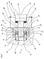
- einen Längsschnitt eines erfindungsgemäßen Entlüftungsventils einer thermischen Entgratanlage.
- Fig. 1
- a longitudinal section of a vent valve according to the invention a thermal deburring system.
Das in
Das Entlüftungsventil 10 ist im Gehäuse 42 der Entgratkammer einbaut und über den Entlüftungsdurchgang 11 mit dieser verbunden. Die Achse A des Entlüftungsventils verläuft in Durchgangsrichtung D.The
Das Entlüftungsventil 10 umfasst einen Ventilsitz 12 und einen Ventilstößel 20. Der Ventilstößel 20 ist mit einem vereinfacht dargestellten Aktuator 40, nämlich der Kolbenstange 45 eines einfachwirkenden Pneumatikzylinders, so verbunden, dass er in Richtung der Entlüftungsventilachse A bewegt werden kann. Bei der Schließbewegung des Entlüftungsventils 10 wird die Antriebskraft mittels Druckluft bereitgestellt, die über die Druckluftleitung 43 zugeführt wird. Die Rückstellkraft zum Öffnen des Entlüftungsventils 10 wird von der Rückstellfeder 44 erzeugt. Der Aktuator ist über einen ebenfalls vereinfacht dargestellten Bajonettverschluss 41 mit dem Gehäuse 42 der Entgratkammer lösbar verbunden.The
Am Ventilstößel 20 ist eine Dichtung 23 angebracht, die in Kontakt mit dem Ventilsitz 12 bringbar ist. Der Ventilstößel bildet somit den Dichtungsträger 21. Die Dichtung wird von einem inneren Ring 24, einem äußeren Ring 25 und einem verformbaren Ringkern 26 gebildet, die in einer angepassten Ausnehmung 28 aufgenommen sind. Die beiden Ringe 24, 25 bestehen aus Messing oder nichtrostendem Stahl während der verformbare Ringkern 26 aus PTFE hergestellt ist. Beim Schließen des Entlüftungsventils 10 wird der verformbare Ringkern 26 allseitig mit Druck beaufschlagt, so dass er in die Verdrängungsausnehmungen 27 fließt, die an den beiden Ringen 24, 25 und am Ventilstößel 20 angebracht sind. Die Verdrängungsausnehmungen 27 sind in allen drei Fällen als umlaufende Nuten ausgeführt.On the
Am Ventilstößel 20 ist ein zylindrischer Schutzfortsatz 22 vorgesehen, an dessen Außenumfangsfläche der innere Ring 24 spielfrei angeordnet ist. Der Innendurchmesser des inneren Rings 24 ist gleich dem Innendurchmesser des zylindrischen Entlüftungsdurchgangs 11 ausgeführt.On the
Der Ventilsitz 12 wird von einem ringförmigen Ventileinsatz 13 gebildet, der einstückig als Drehteil aus Stahl hergestellt ist. Der Ventileinsatz 13 weist an der dem Ventilstößel zugewandten Stirnseite eine konvexe Dichtfläche 15 auf, die von einer inneren Kegelfläche 16 und einer äußeren Kegelfläche 17 gebildet wird, so dass sie spitz zuläuft. Die Spitze ist in der Verlängerung der Fügefläche zwischen innerem Ring 24 und Ringkern 26 angeordnet, damit sich eine unkomplizierte Stirnfläche des Ringkerns ergibt.The
Der kleinste Innendurchmesser des Ventileinsatzes 13 ist kleiner als der Innendurchmesser des Entlüftungsdurchgangs 11. Dieser Innendurchmesser liegt nur entlang eines Abschnitts 18 am Ventileinsatz vor, so dass sich in Verbindung mit dem Schutzfortsatz 22 im geschlossenen Zustand des Entlüftungsventils 10 ein Dichtungslabyrinth ergibt.The smallest inner diameter of the
An der Außenumfangsfläche des Ventileinsatzes 13 ist ein Gummi-O-Ring 14 vorgesehen, der in einer umlaufenden Nut unter Vorspannung eingebaut ist.On the outer peripheral surface of the
- DD
- DurchgangsrichtungThe direction of passage
- AA
- EntlüftungsventilachseVentilation valve axis
- 1010
- Entlüftungsventilvent valve
- 1111
- EntlüftungsdurchgangVent passage
- 1212
- Ventilsitzvalve seat
- 1313
- Ventileinsatzvalve core
- 1414
- O-RingO-ring
- 1515
- Dichtflächesealing surface
- 1616
- innere Kegelflächeinner conical surface
- 1717
- äußere Kegelflächeouter cone surface
- 1818
- Abschnitt mit kleinstem InnendurchmesserSection with the smallest inner diameter
- 2020
- Ventilstößeltappet
- 2121
- Dichtungsträgerseal carrier
- 2222
- SchutzfortsatzProtection extension
- 2323
- Dichtungpoetry
- 2424
- innerer Ringinner ring
- 2525
- äußerer Ringouter ring
- 2626
- Ringkerntoroidal
- 2727
- Verdrängungsausnehmungdisplacement recess
- 2828
- Ausnehmungrecess
- 4040
- Aktuatoractuator
- 4141
- Bajonettverschlussbayonet catch
- 4242
- Gehäuse der EntgratkammerHousing of the deburring chamber
- 4343
- DruckluftleitungCompressed air line
- 4444
- RückstellfederReturn spring
- 4545
- Kolbenstangepiston rod
Claims (10)
- Thermal deburring plant with a deburring chamber which is closable, pressure-tight, and which is connected to the surroundings via a venting passage (11) closable by means of a venting valve (10) and having a passage direction (D), the venting valve (10) having a stationary valve seat (12), which surrounds the venting passage (11), a valve tappet (20) movable in the passage direction (D) and a seal (23), characterized in that the seal (23) is attached to the valve tappet (20) such that the area of the valve tappet on which an explosive pressure from the deburring chamber acts is essentially equal to the cross-sectional area of the venting passage.
- Thermal deburring plant according to Claim 1, characterized in that the valve tappet (20) is drivable by an actuator (40), preferably a single-acting fluid cylinder, the composite structure which consists of the valve tappet (20) and of the actuator (40) being connected releasably to the deburring chamber, preferably by means of a bayonet fastening (41).
- Thermal deburring plant according to one of the preceding claims, characterized in that the seal (23) is formed by an inner ring (24), an outer ring (25) and a deformable annular core (26) which are received in an adapted recess (28) of the valve tappet (20), the two rings (24; 25) being capable of being brought into contact with the valve seat (12) such that the deformable annular core (26) is acted upon on all sides by pressure.
- Thermal deburring plant according to Claim 3, characterized in that at least one ring (24; 25) and/or the valve tappet (20) have/has a displacement recess (27) for the deformable annular core (26).
- Thermal deburring plant according to Claim 4, characterized in that the displacement recess (27) is designed as a continuous groove.
- Thermal deburring plant according to one of Claims 3 to 5, characterized in that the inside diameter of the inner ring (24) is essentially equal to the inside diameter of the venting passage (11).
- Thermal deburring plant according to one of the preceding claims, characterized in that the valve seat (12) is formed by an annular valve insert (13), on the end face of which is provided a sealing face (15) which, as seen in longitudinal section, is of convex, preferably tapering design.
- Thermal deburring plant according to Claim 7, characterized in that the inside diameter of the valve insert (13) is in portions smaller than the inside diameter of the inner ring (24).
- Thermal deburring plant according to Claim 8, characterized in that the valve tappet (20) projects with a protective extension (22) into the valve insert (13) when the venting valve (10) is in the closed state.
- Thermal deburring plant according to one of Claims 7 to 9, characterized in that a static seal, preferably an O-ring (14), is provided on the outer circumferential face of the valve insert (10).
Applications Claiming Priority (1)
| Application Number | Priority Date | Filing Date | Title |
|---|---|---|---|
| DE102006013667A DE102006013667A1 (en) | 2006-03-24 | 2006-03-24 | Thermal deburring system with quick exhaust |
Publications (3)
| Publication Number | Publication Date |
|---|---|
| EP1837111A2 EP1837111A2 (en) | 2007-09-26 |
| EP1837111A3 EP1837111A3 (en) | 2008-09-10 |
| EP1837111B1 true EP1837111B1 (en) | 2009-09-09 |
Family
ID=38080984
Family Applications (1)
| Application Number | Title | Priority Date | Filing Date |
|---|---|---|---|
| EP07004295A Expired - Fee Related EP1837111B1 (en) | 2006-03-24 | 2007-03-02 | Thermal deburring installation with rapid ventilation |
Country Status (5)
| Country | Link |
|---|---|
| US (1) | US7708255B2 (en) |
| EP (1) | EP1837111B1 (en) |
| JP (1) | JP2007253325A (en) |
| CN (1) | CN101041193B (en) |
| DE (2) | DE102006013667A1 (en) |
Cited By (1)
| Publication number | Priority date | Publication date | Assignee | Title |
|---|---|---|---|---|
| DE102013219677A1 (en) | 2013-09-30 | 2015-04-02 | Robert Bosch Gmbh | Thermal deburring system with movable support assembly |
Families Citing this family (3)
| Publication number | Priority date | Publication date | Assignee | Title |
|---|---|---|---|---|
| US7922833B2 (en) | 2008-08-05 | 2011-04-12 | Kennametal Inc. | Gas regulator for thermal energy machining |
| DE102010055747B3 (en) * | 2010-12-22 | 2012-07-05 | Magna Steyr Fahrzeugtechnik Ag & Co Kg | pressure reducer |
| DE102013111992B3 (en) * | 2013-10-30 | 2015-01-22 | Günther Spelsberg GmbH & Co. KG | Housing with ventilation element |
Family Cites Families (14)
| Publication number | Priority date | Publication date | Assignee | Title |
|---|---|---|---|---|
| US2240521A (en) * | 1939-12-16 | 1941-05-06 | Wagner Electric Corp | Master cylinder valve |
| GB1447725A (en) * | 1974-02-25 | 1976-08-25 | Laws P | Valves |
| DE2424148C2 (en) | 1974-05-17 | 1983-08-11 | Robert Bosch Gmbh, 7000 Stuttgart | Gas-tight valve for machines for the treatment of materials with high temperature and pressure surges |
| US4014510A (en) * | 1975-09-05 | 1977-03-29 | Midcon Pipeline Equipment Co. | Pilot valve |
| EP0246271A4 (en) * | 1985-10-04 | 1988-02-15 | Brunswick Valve & Control | Pressure relief valve having a novel poppet seal. |
| US5193577A (en) * | 1990-06-25 | 1993-03-16 | Holthuis B.V | Sludge pump valve |
| CN2148226Y (en) * | 1993-01-12 | 1993-12-01 | 威海市东华机械厂 | Mix block air inlet and outlet valve mechanism for thermal chip removing machine |
| US5618025A (en) * | 1996-05-23 | 1997-04-08 | Fisher Controls International, Inc. | Protected soft seat with secondary hard seat |
| CN2305532Y (en) * | 1997-06-09 | 1999-01-27 | 凌恒干 | Over pressure safety dynamic and static sealed directional discharge valve |
| GB2343498A (en) * | 1998-11-03 | 2000-05-10 | Seetru Ltd | Safety valve with shape-recoverable sealing element |
| US6227240B1 (en) * | 1999-10-13 | 2001-05-08 | National-Oilwell L.P. | Unitized spherical profile check valve with replaceable sealing element |
| DE10106966A1 (en) * | 2001-02-15 | 2002-08-29 | Bosch Gmbh Robert | Device for thermal deburring of workpieces |
| DE10106967A1 (en) * | 2001-02-15 | 2002-08-29 | Bosch Gmbh Robert | Device for thermal deburring of workpieces |
| US7036523B2 (en) * | 2001-06-22 | 2006-05-02 | Kenneth Nixon | Serviceable check valve |
-
2006
- 2006-03-24 DE DE102006013667A patent/DE102006013667A1/en not_active Withdrawn
-
2007
- 2007-01-19 US US11/624,833 patent/US7708255B2/en not_active Expired - Fee Related
- 2007-03-02 EP EP07004295A patent/EP1837111B1/en not_active Expired - Fee Related
- 2007-03-02 DE DE502007001465T patent/DE502007001465D1/en active Active
- 2007-03-22 CN CN2007100887693A patent/CN101041193B/en not_active Expired - Fee Related
- 2007-03-23 JP JP2007076582A patent/JP2007253325A/en active Pending
Cited By (1)
| Publication number | Priority date | Publication date | Assignee | Title |
|---|---|---|---|---|
| DE102013219677A1 (en) | 2013-09-30 | 2015-04-02 | Robert Bosch Gmbh | Thermal deburring system with movable support assembly |
Also Published As
| Publication number | Publication date |
|---|---|
| DE102006013667A1 (en) | 2007-09-27 |
| US20070221875A1 (en) | 2007-09-27 |
| EP1837111A3 (en) | 2008-09-10 |
| US7708255B2 (en) | 2010-05-04 |
| CN101041193B (en) | 2010-05-26 |
| CN101041193A (en) | 2007-09-26 |
| DE502007001465D1 (en) | 2009-10-22 |
| EP1837111A2 (en) | 2007-09-26 |
| JP2007253325A (en) | 2007-10-04 |
Similar Documents
| Publication | Publication Date | Title |
|---|---|---|
| DE1288392B (en) | Rotary valve | |
| EP2049794B1 (en) | Sealing and guiding device for a piston of a piston pump | |
| DE1576168B2 (en) | SWITCHING DEVICE FOR AN END SWITCH ATTACHED TO THE CYLINDER HEAD OF A PRESSURIZED PISTON MOTOR | |
| EP2921762B1 (en) | Check valve | |
| EP1837111B1 (en) | Thermal deburring installation with rapid ventilation | |
| EP3271623B1 (en) | Lifting valve having a rotational decoupling device | |
| EP1678434B1 (en) | Valve, especially a gas safety valve | |
| DE102010033647B4 (en) | Device for sealing a rod against a medium and method for sealing a rod against a medium | |
| DE3418898A1 (en) | Seal arrangement | |
| DE10153142A1 (en) | Valve needle, in particular for spray coating liquid | |
| WO2001051835A1 (en) | Seat valve | |
| EP2732185B1 (en) | High pressure valve | |
| EP0192037B1 (en) | Shut-off device, especially for high-pressure fluids, and use of the device | |
| DE3327901A1 (en) | CALOTTER SLIDER | |
| DE202016102216U1 (en) | Nozzle with sliding gap seal | |
| DE102006022212A1 (en) | Spring arrangement for use as component of compression unit for sealing agent, has locking cover, which is connected with housing by separate locking element | |
| DE60201895T2 (en) | REST PRESSURE VALVE | |
| DE3121317C2 (en) | Sealing of reciprocating machine parts, in particular plunger seals | |
| DE3303877C2 (en) | Single piston valve | |
| DE3003480C2 (en) | ||
| EP3228864B1 (en) | Valve unit for a piston compressor and piston compressor | |
| DE2218376A1 (en) | Composite sealing ring - having harder nose to prevent jamming between components sealed | |
| EP1658456B1 (en) | Sliding valve, in particular, quick-acting sliding valve for an explosion protection shut-off device | |
| DE1994897U (en) | ELASTIC SEALING RING. | |
| DE19547326A1 (en) | Gas spring for motor vehicle |
Legal Events
| Date | Code | Title | Description |
|---|---|---|---|
| PUAI | Public reference made under article 153(3) epc to a published international application that has entered the european phase |
Free format text: ORIGINAL CODE: 0009012 |
|
| AK | Designated contracting states |
Kind code of ref document: A2 Designated state(s): AT BE BG CH CY CZ DE DK EE ES FI FR GB GR HU IE IS IT LI LT LU LV MC MT NL PL PT RO SE SI SK TR |
|
| AX | Request for extension of the european patent |
Extension state: AL BA HR MK YU |
|
| RIC1 | Information provided on ipc code assigned before grant |
Ipc: B23D 79/02 20060101ALI20080522BHEP Ipc: F16K 1/46 20060101ALI20080522BHEP Ipc: B23D 79/00 20060101AFI20070619BHEP |
|
| PUAL | Search report despatched |
Free format text: ORIGINAL CODE: 0009013 |
|
| AK | Designated contracting states |
Kind code of ref document: A3 Designated state(s): AT BE BG CH CY CZ DE DK EE ES FI FR GB GR HU IE IS IT LI LT LU LV MC MT NL PL PT RO SE SI SK TR |
|
| AX | Request for extension of the european patent |
Extension state: AL BA HR MK RS |
|
| 17P | Request for examination filed |
Effective date: 20080828 |
|
| GRAP | Despatch of communication of intention to grant a patent |
Free format text: ORIGINAL CODE: EPIDOSNIGR1 |
|
| GRAS | Grant fee paid |
Free format text: ORIGINAL CODE: EPIDOSNIGR3 |
|
| AKX | Designation fees paid |
Designated state(s): DE FR IT |
|
| GRAA | (expected) grant |
Free format text: ORIGINAL CODE: 0009210 |
|
| AK | Designated contracting states |
Kind code of ref document: B1 Designated state(s): DE FR IT |
|
| REF | Corresponds to: |
Ref document number: 502007001465 Country of ref document: DE Date of ref document: 20091022 Kind code of ref document: P |
|
| PLBE | No opposition filed within time limit |
Free format text: ORIGINAL CODE: 0009261 |
|
| STAA | Information on the status of an ep patent application or granted ep patent |
Free format text: STATUS: NO OPPOSITION FILED WITHIN TIME LIMIT |
|
| 26N | No opposition filed |
Effective date: 20100610 |
|
| PG25 | Lapsed in a contracting state [announced via postgrant information from national office to epo] |
Ref country code: IT Free format text: LAPSE BECAUSE OF NON-PAYMENT OF DUE FEES Effective date: 20100302 |
|
| REG | Reference to a national code |
Ref country code: FR Ref legal event code: PLFP Year of fee payment: 10 |
|
| REG | Reference to a national code |
Ref country code: FR Ref legal event code: PLFP Year of fee payment: 11 |
|
| REG | Reference to a national code |
Ref country code: FR Ref legal event code: PLFP Year of fee payment: 12 |
|
| PGFP | Annual fee paid to national office [announced via postgrant information from national office to epo] |
Ref country code: FR Payment date: 20190326 Year of fee payment: 13 Ref country code: IT Payment date: 20190321 Year of fee payment: 13 |
|
| PGFP | Annual fee paid to national office [announced via postgrant information from national office to epo] |
Ref country code: DE Payment date: 20190520 Year of fee payment: 13 |
|
| REG | Reference to a national code |
Ref country code: DE Ref legal event code: R119 Ref document number: 502007001465 Country of ref document: DE |
|
| PG25 | Lapsed in a contracting state [announced via postgrant information from national office to epo] |
Ref country code: DE Free format text: LAPSE BECAUSE OF NON-PAYMENT OF DUE FEES Effective date: 20201001 Ref country code: FR Free format text: LAPSE BECAUSE OF NON-PAYMENT OF DUE FEES Effective date: 20200331 |
|
| PG25 | Lapsed in a contracting state [announced via postgrant information from national office to epo] |
Ref country code: IT Free format text: LAPSE BECAUSE OF NON-PAYMENT OF DUE FEES Effective date: 20200302 |