EP1837111B1 - Installation d'ébarbage thermique dotée d'une ventilation rapide - Google Patents
Installation d'ébarbage thermique dotée d'une ventilation rapide Download PDFInfo
- Publication number
- EP1837111B1 EP1837111B1 EP07004295A EP07004295A EP1837111B1 EP 1837111 B1 EP1837111 B1 EP 1837111B1 EP 07004295 A EP07004295 A EP 07004295A EP 07004295 A EP07004295 A EP 07004295A EP 1837111 B1 EP1837111 B1 EP 1837111B1
- Authority
- EP
- European Patent Office
- Prior art keywords
- valve
- plant according
- thermal deburring
- seal
- venting
- Prior art date
- Legal status (The legal status is an assumption and is not a legal conclusion. Google has not performed a legal analysis and makes no representation as to the accuracy of the status listed.)
- Expired - Fee Related
Links
Images
Classifications
-
- B—PERFORMING OPERATIONS; TRANSPORTING
- B23—MACHINE TOOLS; METAL-WORKING NOT OTHERWISE PROVIDED FOR
- B23D—PLANING; SLOTTING; SHEARING; BROACHING; SAWING; FILING; SCRAPING; LIKE OPERATIONS FOR WORKING METAL BY REMOVING MATERIAL, NOT OTHERWISE PROVIDED FOR
- B23D79/00—Methods, machines, or devices not covered elsewhere, for working metal by removal of material
- B23D79/005—Methods, machines, or devices not covered elsewhere, for working metal by removal of material for thermal deburring
-
- F—MECHANICAL ENGINEERING; LIGHTING; HEATING; WEAPONS; BLASTING
- F16—ENGINEERING ELEMENTS AND UNITS; GENERAL MEASURES FOR PRODUCING AND MAINTAINING EFFECTIVE FUNCTIONING OF MACHINES OR INSTALLATIONS; THERMAL INSULATION IN GENERAL
- F16K—VALVES; TAPS; COCKS; ACTUATING-FLOATS; DEVICES FOR VENTING OR AERATING
- F16K24/00—Devices, e.g. valves, for venting or aerating enclosures
Definitions
- the invention relates to a thermal deburring system with quick exhaust according to the preamble of claim 1.
- Such a thermal deburring is from the EP 1 232 822 A1 known.
- Fig. 1 a thermal Entgratstrom with a Entgrathunt 2 shown, which is connected via a vent passage 22 to the environment, via the suction 23.
- the vent passage 22 is closed with a vent valve 21.
- Such a quick exhaust is used for controlled discharge of high-pressure combustion gases after the explosion of the fuel gases, which causes the deburring of the introduced into the Entgrathunt 2 workpieces 3.
- FIG EP 1 232 822 A1 An embodiment of the venting valve 21 is shown in FIG EP 1 232 822 A1 shown in more detail. It comprises a valve seat 28 which is fixedly connected to the deburring chamber 2 and a valve tappet 25 which can be moved in the direction of the ventilation passage 15. The seal 26 is attached to the valve seat.
- This vent valve has the disadvantage that the locking force of the valve stem during the explosion, ie the force that is necessary to push the valve stem against the valve seat so that no combustion gases can escape, is very high.
- vent valve has substantially the same flow cross section for the explosion exhaust as the vent passage and thus does not act as a throttle point, which hinders a rapid removal of the combustion gases.
- the cycle time of the thermal deburring system is correspondingly short.
- valve tappet can be driven by an actuator, preferably a single-acting fluid cylinder, wherein the composite of valve tappet and actuator is detachably connected to the deburring chamber, preferably by means of a bayonet closure.
- actuator preferably a single-acting fluid cylinder
- the composite of valve tappet and actuator is detachably connected to the deburring chamber, preferably by means of a bayonet closure.
- the preferred embodiment of the releasable connection as a bayonet closure ie a connection in which first a straight-line joining movement in the direction of the vent valve axis and then a rotating locking movement is performed around the vent valve axis, has the advantage that the assembly or disassembly of the composite valve stem and Actuator is particularly easy and fast.
- a bayonet closure has the advantage that the joining surfaces that must withstand the explosive forces can be made very large. It may be provided a latching connection, which secures the bayonet lock in the locked position, so that an accidental opening is excluded.
- the preferred embodiment of the actuator as a single-acting fluid cylinder in particular as a short-stroke cylinder has the advantage that it can be made very short in the direction of the vent valve axis, so that the composite of valve stem and actuator during maintenance is easy to handle.
- a driving fluid compressed air or hydraulic fluid into consideration with compressed air is usually cheaper.
- the seal may be formed by an inner ring, an outer ring and a deformable ring core, which are received in a matched recess of the valve stem, wherein the two rings are brought into contact with the associated valve seat, that the deformable toroidal sides with Pressure is applied.
- This embodiment is basically of the EP 1 232 822 A1 suggested.
- the deformable toroidal core is preferably a PTFE ring, which deforms only under the relatively high contact pressure forces and in the subsequent discharge partially resiliently springs back, so that there may be gaps between the seal and the recess. This problem is particularly serious if the seal is located on a moving part such as the valve lifter or if the seal can fall out of the fitted recess due to its own weight.
- the valve tappet has a displacement recess for the deformable toroidal core.
- the deformable annular core will flow into the displacement recesses under the action of the contact pressure.
- the elastic resilience of the deformable toroidal core will not be sufficient to cancel the positive connection between the sealing components.
- the seal is thus positively secured against loosening.
- the Dichtungsrohmaschine can be performed without undercuts, so that they can be inexpensively manufactured separately from each other and then easily assembled. The positive connection is produced only during operation of the thermal deburring system.
- the displacement recess may be formed as a circumferential groove so that it can be easily and inexpensively manufactured by means of a turning operation. Although a rotation of the seal is not prevented by such a displacement recess, but this is irrelevant, since the seal, the valve lifter and the valve seat are preferably rotationally symmetrical to the vent valve axis, so that they are fully functional in any rotational position.
- the inner diameter of the inner ring may be substantially equal to the inner diameter of the vent passage.
- valve seat may be formed by an annular valve insert, on the end face of a sealing surface is provided, which is viewed in longitudinal section convex preferably formed tapered point.
- the design of the valve seat as a separate valve insert has the advantage that it can be easily changed when worn. In addition, it can be made of a different wear-resistant material than the rest of the deburring.
- the tapered sealing surface has the advantage that it is less expensive to produce than a flattened sealing surface EP 1 232 822 A1 - Fig. 5, because less tolerant length dimensions are observed.
- the convex shape is needed so that the rings of the gasket are pressed against the mating recess to prevent outflow of the deformable toroidal core.
- valve stem protrudes in the closed state of the vent valve with a protective extension in the valve core.
- a narrow gap between the valve core and the valve tappet is formed, which additionally brakes the explosion pressure wave on its way to the seal and thus protects them from damage.
- a static seal preferably an O-ring may be provided on the outer peripheral surface of the valve core.
- These Gasket is required so that the combustion gases, which are filled under high pressure in the combustion chamber, can not escape on the outer peripheral surface of the valve insert over.
- the preferred embodiment has the advantage that withdrawal of the valve insert during opening of the venting valve is avoided by the high static friction of the sealing rubber.
- vent valve 10 comes in a thermal deburring according to EP 1 232 822 A1
- EP 1 232 822 A1 For use and as a replacement for the vent valve of FIG. 5.
- thermal deburring system For the general structure of the thermal deburring system, reference is therefore made to this application.
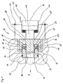
- the vent valve 10 is installed in the housing 42 of the Entgrathunt and connected via the vent passage 11 with this.
- the axis A of the vent valve extends in the passage D.
- the vent valve 10 includes a valve seat 12 and a valve lifter 20.
- the valve lifter 20 is connected to a simplified illustrated actuator 40, namely the piston rod 45 of a single-acting pneumatic cylinder, so that it can be moved in the direction of the vent valve axis A.
- the driving force is provided by means of compressed air, which is supplied via the compressed air line 43.
- the restoring force for opening the venting valve 10 is generated by the return spring 44.
- the actuator is detachably connected to the housing 42 of the deburring chamber via a bayonet lock 41, which is likewise shown in simplified form.
- a seal 23 is mounted, which can be brought into contact with the valve seat 12.
- the valve stem thus forms the seal carrier 21.
- the seal is formed by an inner ring 24, an outer ring 25 and a deformable annular core 26, which are received in a matching recess 28.
- the two rings 24, 25 are made of brass or stainless steel while the deformable ring core 26 is made of PTFE.
- the deformable annular core 26 is pressurized on all sides, so that it flows into the displacement recesses 27, which are attached to the two rings 24, 25 and the valve stem 20.
- the displacement recesses 27 are designed in all three cases as circumferential grooves.
- a cylindrical protective extension 22 is provided, on the outer peripheral surface of the inner ring 24 is arranged without play.
- the inner diameter of the inner ring 24 is made equal to the inner diameter of the cylindrical vent passage 11.
- the valve seat 12 is formed by an annular valve insert 13, which is made in one piece as a turned part made of steel.
- the valve insert 13 has, on the end face facing the valve tappet, a convex sealing surface 15, which is formed by an inner conical surface 16 and an outer conical surface 17, so that it tapers to a point.
- the tip is arranged in the extension of the joining surface between inner ring 24 and ring core 26, so that there is an uncomplicated end face of the toroidal core.
- the smallest inner diameter of the valve insert 13 is smaller than the inner diameter of the vent passage 11. This inner diameter is present only along a portion 18 on the valve core, so that results in conjunction with the protective extension 22 in the closed state of the vent valve 10 is a sealing labyrinth.
- a rubber O-ring 14 is provided, which is installed in a circumferential groove under bias.
Claims (10)
- Installation d'ébarbage thermique comprenant une chambre d'ébarbage pouvant être fermée de manière étanche à la pression, qui est connectée à l'environnement par le biais d'un passage de désaérage (11) avec une direction de passage (D) et pouvant être fermé au moyen d'une soupape de désaérage (10), la soupape de désaérage (10) présentant un siège de soupape fixe (12) qui entoure le passage de désaérage (11), un poussoir de soupape (20) déplaçable dans la direction du passage (D) et un joint d'étanchéité (23),
caractérisée en ce que le joint d'étanchéité (23) est monté sur le poussoir de soupape (20) de telle sorte que la surface du poussoir de soupape sur laquelle agit une pression d'explosion provenant de la chambre d'ébarbage soit essentiellement identique à la surface en section transversale du passage de désaérage. - Installation d'ébarbage thermique selon la revendication 1,
caractérisée en ce que le poussoir de soupape (20) peut être entraîné par un actionneur (40) de préférence un cylindre de fluide agissant avec simple effet, l'assemblage du poussoir de soupape (20) et de l'actionneur (40) étant connecté de manière desserrable à la chambre d'ébarbage, de préférence au moyen d'une fermeture à baïonnette (41). - Installation d'ébarbage thermique selon l'une quelconque des revendications précédentes,
caractérisée en ce que le joint d'étanchéité (23) est formé par une bague interne (24), une bague externe (25) et un noyau annulaire déformable (26), lesquels sont reçus dans un évidement adapté (28) du poussoir de soupape (20), les deux bagues (24 ; 25) pouvant être amenées en contact avec le siège de soupape (12) de telle sorte que le noyau annulaire déformable (26) soit sollicité de tous les côtés par la pression. - Installation d'ébarbage thermique selon la revendication 3,
caractérisée en ce
qu'au moins une bague (24 ; 25) et/ou le poussoir de soupape (20) présente un évidement de refoulement (27) pour le noyau annulaire déformable (26). - Installation d'ébarbage thermique selon la revendication 4,
caractérisée en ce que
l'évidement de refoulement (27) est réalisé sous forme de rainure périphérique. - Installation d'ébarbage thermique selon l'une quelconque des revendications 3 à 5,
caractérisée en ce que
le diamètre intérieur de la bague interne (25) est essentiellement identique au diamètre intérieur du passage de désaérage (11). - Installation d'ébarbage thermique selon l'une quelconque des revendications précédentes,
caractérisée en ce que
le siège de soupape (12) est formé par un insert de soupape annulaire (13), sur la surface frontale duquel est prévue une surface d'étanchéité (15) qui est réalisée, vue en coupe longitudinale, en se terminant de manière convexe ou en pointe. - Installation d'ébarbage thermique selon la revendication 7,
caractérisée en ce que le diamètre intérieur de l'insert de soupape (13) est plus petit par portions que le diamètre intérieur de la bague interne (24). - Installation d'ébarbage thermique selon la revendication 8,
caractérisée en ce que
le poussoir de soupape (20) pénètre dans l'état fermé de la soupape de désaérage (10) avec une saillie de protection (22) dans l'insert de soupape (13). - Installation d'ébarbage thermique selon l'une quelconque des revendications 7 à 9,
caractérisée en ce que
l'on prévoit sur la surface périphérique extérieure de l'insert de soupape (10) un joint d'étanchéité statique, de préférence un joint torique (14).
Applications Claiming Priority (1)
| Application Number | Priority Date | Filing Date | Title |
|---|---|---|---|
| DE102006013667A DE102006013667A1 (de) | 2006-03-24 | 2006-03-24 | Thermische Entgratanlage mit Schnellentlüftung |
Publications (3)
| Publication Number | Publication Date |
|---|---|
| EP1837111A2 EP1837111A2 (fr) | 2007-09-26 |
| EP1837111A3 EP1837111A3 (fr) | 2008-09-10 |
| EP1837111B1 true EP1837111B1 (fr) | 2009-09-09 |
Family
ID=38080984
Family Applications (1)
| Application Number | Title | Priority Date | Filing Date |
|---|---|---|---|
| EP07004295A Expired - Fee Related EP1837111B1 (fr) | 2006-03-24 | 2007-03-02 | Installation d'ébarbage thermique dotée d'une ventilation rapide |
Country Status (5)
| Country | Link |
|---|---|
| US (1) | US7708255B2 (fr) |
| EP (1) | EP1837111B1 (fr) |
| JP (1) | JP2007253325A (fr) |
| CN (1) | CN101041193B (fr) |
| DE (2) | DE102006013667A1 (fr) |
Cited By (1)
| Publication number | Priority date | Publication date | Assignee | Title |
|---|---|---|---|---|
| DE102013219677A1 (de) | 2013-09-30 | 2015-04-02 | Robert Bosch Gmbh | Thermische Entgratanlage mit beweglicher Tragbaugruppe |
Families Citing this family (3)
| Publication number | Priority date | Publication date | Assignee | Title |
|---|---|---|---|---|
| US7922833B2 (en) | 2008-08-05 | 2011-04-12 | Kennametal Inc. | Gas regulator for thermal energy machining |
| DE102010055747B3 (de) * | 2010-12-22 | 2012-07-05 | Magna Steyr Fahrzeugtechnik Ag & Co Kg | Druckminderer |
| DE102013111992B3 (de) * | 2013-10-30 | 2015-01-22 | Günther Spelsberg GmbH & Co. KG | Gehäuse mit Belüftungselement |
Family Cites Families (14)
| Publication number | Priority date | Publication date | Assignee | Title |
|---|---|---|---|---|
| US2240521A (en) * | 1939-12-16 | 1941-05-06 | Wagner Electric Corp | Master cylinder valve |
| GB1447725A (en) * | 1974-02-25 | 1976-08-25 | Laws P | Valves |
| DE2424148C2 (de) | 1974-05-17 | 1983-08-11 | Robert Bosch Gmbh, 7000 Stuttgart | Gasdichtes Ventil für Maschinen zur Behandlung von Materialien mit hohen Temperatur- und Druckstößen |
| US4014510A (en) * | 1975-09-05 | 1977-03-29 | Midcon Pipeline Equipment Co. | Pilot valve |
| WO1987002113A1 (fr) * | 1985-10-04 | 1987-04-09 | Brunswick Valve & Control, Inc. | Soupape d'abaissement de la pression ayant un nouveau joint d'etancheite soulevant |
| US5193577A (en) * | 1990-06-25 | 1993-03-16 | Holthuis B.V | Sludge pump valve |
| CN2148226Y (zh) * | 1993-01-12 | 1993-12-01 | 威海市东华机械厂 | 热力去毛刺机混合块进出气体阀门机构 |
| US5618025A (en) * | 1996-05-23 | 1997-04-08 | Fisher Controls International, Inc. | Protected soft seat with secondary hard seat |
| CN2305532Y (zh) * | 1997-06-09 | 1999-01-27 | 凌恒干 | 超压保险动静密封定向放气阀 |
| GB2343498A (en) * | 1998-11-03 | 2000-05-10 | Seetru Ltd | Safety valve with shape-recoverable sealing element |
| US6227240B1 (en) * | 1999-10-13 | 2001-05-08 | National-Oilwell L.P. | Unitized spherical profile check valve with replaceable sealing element |
| DE10106967A1 (de) * | 2001-02-15 | 2002-08-29 | Bosch Gmbh Robert | Vorrichtung zum thermischen Entgraten von Werkstücken |
| DE10106966A1 (de) * | 2001-02-15 | 2002-08-29 | Bosch Gmbh Robert | Vorrichtung zum thermischen Entgraten von Werkstücken |
| US7036523B2 (en) * | 2001-06-22 | 2006-05-02 | Kenneth Nixon | Serviceable check valve |
-
2006
- 2006-03-24 DE DE102006013667A patent/DE102006013667A1/de not_active Withdrawn
-
2007
- 2007-01-19 US US11/624,833 patent/US7708255B2/en not_active Expired - Fee Related
- 2007-03-02 DE DE502007001465T patent/DE502007001465D1/de active Active
- 2007-03-02 EP EP07004295A patent/EP1837111B1/fr not_active Expired - Fee Related
- 2007-03-22 CN CN2007100887693A patent/CN101041193B/zh not_active Expired - Fee Related
- 2007-03-23 JP JP2007076582A patent/JP2007253325A/ja active Pending
Cited By (1)
| Publication number | Priority date | Publication date | Assignee | Title |
|---|---|---|---|---|
| DE102013219677A1 (de) | 2013-09-30 | 2015-04-02 | Robert Bosch Gmbh | Thermische Entgratanlage mit beweglicher Tragbaugruppe |
Also Published As
| Publication number | Publication date |
|---|---|
| DE102006013667A1 (de) | 2007-09-27 |
| DE502007001465D1 (de) | 2009-10-22 |
| JP2007253325A (ja) | 2007-10-04 |
| US20070221875A1 (en) | 2007-09-27 |
| CN101041193B (zh) | 2010-05-26 |
| EP1837111A2 (fr) | 2007-09-26 |
| CN101041193A (zh) | 2007-09-26 |
| US7708255B2 (en) | 2010-05-04 |
| EP1837111A3 (fr) | 2008-09-10 |
Similar Documents
| Publication | Publication Date | Title |
|---|---|---|
| DE1288392B (de) | Drehschieber | |
| EP2049794B1 (fr) | Dispositif d'étancheité et de guidage pour un piston d'une pompe à piston | |
| DE1576168B2 (de) | Schaltvorrichtung fuer einen am zylinderkopf eines druckmittelbetaetigten kolbenmotors angebrachten end schalter | |
| EP2921762B1 (fr) | Vanne d'arrêt | |
| EP1837111B1 (fr) | Installation d'ébarbage thermique dotée d'une ventilation rapide | |
| EP3271623B1 (fr) | Robinet à soupape comportant un dispositif de désaccouplement rotatif | |
| EP1678434B1 (fr) | Soupape, notamment soupape de securite a gaz | |
| DE102010033647B4 (de) | Vorrichtung zum Abdichten einer Stange gegenüber einem Medium und Verfahren zum Abdichten einer Stange gegenüber einem Medium | |
| DE3418898A1 (de) | Dichtungsanordnung | |
| DE3942408A1 (de) | Trockenlaufende gasdichtung | |
| DE10153142A1 (de) | Ventilnadel, insbesondere für Spritzbeschichtungsflüssigkeit | |
| WO2001051835A1 (fr) | Soupape de siege | |
| EP2732185B1 (fr) | Vanne à haute pression | |
| EP0192037B1 (fr) | Dispositif d'obturation, en particulier pour des fluides à haute pression et application de ce dispositif | |
| DE3327901A1 (de) | Kalottenschieber | |
| DE202016102216U1 (de) | Düse mit Gleitspaltdichtung | |
| DE102006022212A1 (de) | Federanordnung | |
| DE60201895T2 (de) | Restdruckventil | |
| DE3121317C2 (de) | Abdichtung hin- und hergehender Maschinenteile, insbesondere Plungerdichtung | |
| DE3303877C2 (de) | Einzelstempelventil | |
| DE3003480C2 (fr) | ||
| EP3228864B1 (fr) | Unite de soupape pour un compresseur a piston et compresseur a piston | |
| DE2218376A1 (de) | Aus elastischem Material bestehender Dichtungsring | |
| EP1658456B1 (fr) | Coulisseau, en particulier coulisseau a fermeture rapide pour un dispositif d'arret et de protection contre les explosions | |
| DE1994897U (de) | Elastischer dichtungsring. |
Legal Events
| Date | Code | Title | Description |
|---|---|---|---|
| PUAI | Public reference made under article 153(3) epc to a published international application that has entered the european phase |
Free format text: ORIGINAL CODE: 0009012 |
|
| AK | Designated contracting states |
Kind code of ref document: A2 Designated state(s): AT BE BG CH CY CZ DE DK EE ES FI FR GB GR HU IE IS IT LI LT LU LV MC MT NL PL PT RO SE SI SK TR |
|
| AX | Request for extension of the european patent |
Extension state: AL BA HR MK YU |
|
| RIC1 | Information provided on ipc code assigned before grant |
Ipc: B23D 79/02 20060101ALI20080522BHEP Ipc: F16K 1/46 20060101ALI20080522BHEP Ipc: B23D 79/00 20060101AFI20070619BHEP |
|
| PUAL | Search report despatched |
Free format text: ORIGINAL CODE: 0009013 |
|
| AK | Designated contracting states |
Kind code of ref document: A3 Designated state(s): AT BE BG CH CY CZ DE DK EE ES FI FR GB GR HU IE IS IT LI LT LU LV MC MT NL PL PT RO SE SI SK TR |
|
| AX | Request for extension of the european patent |
Extension state: AL BA HR MK RS |
|
| 17P | Request for examination filed |
Effective date: 20080828 |
|
| GRAP | Despatch of communication of intention to grant a patent |
Free format text: ORIGINAL CODE: EPIDOSNIGR1 |
|
| GRAS | Grant fee paid |
Free format text: ORIGINAL CODE: EPIDOSNIGR3 |
|
| AKX | Designation fees paid |
Designated state(s): DE FR IT |
|
| GRAA | (expected) grant |
Free format text: ORIGINAL CODE: 0009210 |
|
| AK | Designated contracting states |
Kind code of ref document: B1 Designated state(s): DE FR IT |
|
| REF | Corresponds to: |
Ref document number: 502007001465 Country of ref document: DE Date of ref document: 20091022 Kind code of ref document: P |
|
| PLBE | No opposition filed within time limit |
Free format text: ORIGINAL CODE: 0009261 |
|
| STAA | Information on the status of an ep patent application or granted ep patent |
Free format text: STATUS: NO OPPOSITION FILED WITHIN TIME LIMIT |
|
| 26N | No opposition filed |
Effective date: 20100610 |
|
| PG25 | Lapsed in a contracting state [announced via postgrant information from national office to epo] |
Ref country code: IT Free format text: LAPSE BECAUSE OF NON-PAYMENT OF DUE FEES Effective date: 20100302 |
|
| REG | Reference to a national code |
Ref country code: FR Ref legal event code: PLFP Year of fee payment: 10 |
|
| REG | Reference to a national code |
Ref country code: FR Ref legal event code: PLFP Year of fee payment: 11 |
|
| REG | Reference to a national code |
Ref country code: FR Ref legal event code: PLFP Year of fee payment: 12 |
|
| PGFP | Annual fee paid to national office [announced via postgrant information from national office to epo] |
Ref country code: FR Payment date: 20190326 Year of fee payment: 13 Ref country code: IT Payment date: 20190321 Year of fee payment: 13 |
|
| PGFP | Annual fee paid to national office [announced via postgrant information from national office to epo] |
Ref country code: DE Payment date: 20190520 Year of fee payment: 13 |
|
| REG | Reference to a national code |
Ref country code: DE Ref legal event code: R119 Ref document number: 502007001465 Country of ref document: DE |
|
| PG25 | Lapsed in a contracting state [announced via postgrant information from national office to epo] |
Ref country code: DE Free format text: LAPSE BECAUSE OF NON-PAYMENT OF DUE FEES Effective date: 20201001 Ref country code: FR Free format text: LAPSE BECAUSE OF NON-PAYMENT OF DUE FEES Effective date: 20200331 |
|
| PG25 | Lapsed in a contracting state [announced via postgrant information from national office to epo] |
Ref country code: IT Free format text: LAPSE BECAUSE OF NON-PAYMENT OF DUE FEES Effective date: 20200302 |