EP1836715B1 - Elektrodynamisch geöffneten kontaktstruktur für starkstromleistungsschaltergerät - Google Patents
Elektrodynamisch geöffneten kontaktstruktur für starkstromleistungsschaltergerät Download PDFInfo
- Publication number
- EP1836715B1 EP1836715B1 EP06710228.5A EP06710228A EP1836715B1 EP 1836715 B1 EP1836715 B1 EP 1836715B1 EP 06710228 A EP06710228 A EP 06710228A EP 1836715 B1 EP1836715 B1 EP 1836715B1
- Authority
- EP
- European Patent Office
- Prior art keywords
- carrier
- cam
- inner carrier
- withstand
- assembly
- Prior art date
- Legal status (The legal status is an assumption and is not a legal conclusion. Google has not performed a legal analysis and makes no representation as to the accuracy of the status listed.)
- Expired - Lifetime
Links
Images





Classifications
-
- H—ELECTRICITY
- H01—ELECTRIC ELEMENTS
- H01H—ELECTRIC SWITCHES; RELAYS; SELECTORS; EMERGENCY PROTECTIVE DEVICES
- H01H33/00—High-tension or heavy-current switches with arc-extinguishing or arc-preventing means
- H01H33/02—Details
- H01H33/04—Means for extinguishing or preventing arc between current-carrying parts
- H01H33/08—Stationary parts for restricting or subdividing the arc, e.g. barrier plate
-
- H—ELECTRICITY
- H01—ELECTRIC ELEMENTS
- H01H—ELECTRIC SWITCHES; RELAYS; SELECTORS; EMERGENCY PROTECTIVE DEVICES
- H01H1/00—Contacts
- H01H1/12—Contacts characterised by the manner in which co-operating contacts engage
- H01H1/14—Contacts characterised by the manner in which co-operating contacts engage by abutting
- H01H1/22—Contacts characterised by the manner in which co-operating contacts engage by abutting with rigid pivoted member carrying the moving contact
- H01H1/221—Contacts characterised by the manner in which co-operating contacts engage by abutting with rigid pivoted member carrying the moving contact and a contact pressure spring acting between the pivoted member and a supporting member
- H01H1/225—Contacts characterised by the manner in which co-operating contacts engage by abutting with rigid pivoted member carrying the moving contact and a contact pressure spring acting between the pivoted member and a supporting member the supporting member being pivotable
-
- H—ELECTRICITY
- H01—ELECTRIC ELEMENTS
- H01H—ELECTRIC SWITCHES; RELAYS; SELECTORS; EMERGENCY PROTECTIVE DEVICES
- H01H1/00—Contacts
- H01H1/12—Contacts characterised by the manner in which co-operating contacts engage
- H01H1/14—Contacts characterised by the manner in which co-operating contacts engage by abutting
- H01H1/22—Contacts characterised by the manner in which co-operating contacts engage by abutting with rigid pivoted member carrying the moving contact
- H01H1/221—Contacts characterised by the manner in which co-operating contacts engage by abutting with rigid pivoted member carrying the moving contact and a contact pressure spring acting between the pivoted member and a supporting member
- H01H1/226—Contacts characterised by the manner in which co-operating contacts engage by abutting with rigid pivoted member carrying the moving contact and a contact pressure spring acting between the pivoted member and a supporting member having a plurality of parallel contact bars
-
- H—ELECTRICITY
- H01—ELECTRIC ELEMENTS
- H01H—ELECTRIC SWITCHES; RELAYS; SELECTORS; EMERGENCY PROTECTIVE DEVICES
- H01H73/00—Protective overload circuit-breaking switches in which excess current opens the contacts by automatic release of mechanical energy stored by previous operation of a hand reset mechanism
- H01H73/02—Details
- H01H73/18—Means for extinguishing or suppressing arc
-
- H—ELECTRICITY
- H01—ELECTRIC ELEMENTS
- H01H—ELECTRIC SWITCHES; RELAYS; SELECTORS; EMERGENCY PROTECTIVE DEVICES
- H01H77/00—Protective overload circuit-breaking switches operated by excess current and requiring separate action for resetting
- H01H77/02—Protective overload circuit-breaking switches operated by excess current and requiring separate action for resetting in which the excess current itself provides the energy for opening the contacts, and having a separate reset mechanism
- H01H77/10—Protective overload circuit-breaking switches operated by excess current and requiring separate action for resetting in which the excess current itself provides the energy for opening the contacts, and having a separate reset mechanism with electrodynamic opening
- H01H77/102—Protective overload circuit-breaking switches operated by excess current and requiring separate action for resetting in which the excess current itself provides the energy for opening the contacts, and having a separate reset mechanism with electrodynamic opening characterised by special mounting of contact arm, allowing blow-off movement
-
- H—ELECTRICITY
- H01—ELECTRIC ELEMENTS
- H01H—ELECTRIC SWITCHES; RELAYS; SELECTORS; EMERGENCY PROTECTIVE DEVICES
- H01H77/00—Protective overload circuit-breaking switches operated by excess current and requiring separate action for resetting
- H01H77/02—Protective overload circuit-breaking switches operated by excess current and requiring separate action for resetting in which the excess current itself provides the energy for opening the contacts, and having a separate reset mechanism
- H01H77/10—Protective overload circuit-breaking switches operated by excess current and requiring separate action for resetting in which the excess current itself provides the energy for opening the contacts, and having a separate reset mechanism with electrodynamic opening
- H01H77/102—Protective overload circuit-breaking switches operated by excess current and requiring separate action for resetting in which the excess current itself provides the energy for opening the contacts, and having a separate reset mechanism with electrodynamic opening characterised by special mounting of contact arm, allowing blow-off movement
- H01H77/104—Protective overload circuit-breaking switches operated by excess current and requiring separate action for resetting in which the excess current itself provides the energy for opening the contacts, and having a separate reset mechanism with electrodynamic opening characterised by special mounting of contact arm, allowing blow-off movement with a stable blow-off position
-
- H—ELECTRICITY
- H01—ELECTRIC ELEMENTS
- H01H—ELECTRIC SWITCHES; RELAYS; SELECTORS; EMERGENCY PROTECTIVE DEVICES
- H01H9/00—Details of switching devices, not covered by groups H01H1/00 - H01H7/00
- H01H9/30—Means for extinguishing or preventing arc between current-carrying parts
- H01H2009/305—Means for extinguishing or preventing arc between current-carrying parts including means for screening for arc gases as protection of mechanism against hot arc gases or for keeping arc gases in the arc chamber
Definitions
- This invention relates to electric power switching apparatus and in particular to blow open moving contact assemblies for such apparatus with very high current interruption ratings.
- Power circuit breakers typically are used as a main breaker in a power distribution system having additional downstream branch circuit breakers. They are also used as transfer switches for switching between alternative power sources, and as network protectors in larger distribution systems. In such systems, the power circuit breaker must have sufficient withstand capability to allow a downstream breaker to respond to a fault in order to minimize the extent of the outage. However, in the instance of a very large fault, such as a fault just downstream of the power breaker, it is desirable to have the power breaker respond promptly to limit the fault current. It is known to provide a power circuit breaker with a blow open contact structure for this current limiting purpose. This blow opening is driven by the electromagnetic repulsion force on the contacts and is very fast, limiting the actual current to less than the available fault current.
- the contact fingers of the spontaneously opening contact moving structure must have some individual motion with springs to apply contact pressure, supported rigidly until the current-induced force threshold is exceeded.
- the blow open portion of the assembly must have low inertia and be compact for rapid motion from closed to the widest achievable contact gap. When open, the carrier assembly should maintain good dielectric strength across the contact gap and direct the arc produced gases toward the arc chute.
- the contact assembly must accurately control contact location, force and opening threshold and be tolerant of manufacturing variation while being cost-effective to manufacture.
- EP-A-0 827 174 which is entitled "circuit breaker with latch preventing rebound of blow open contact arm".
- the movable contact arms of a circuit breaker are latched in the blow open position to prevent rebound and possible restrike of the arc in response to the very high magnetic repulsion forces generated by a short circuit in the protected electrical system.
- Each movable contact arm is mounted on a secondary carrier coupled to a main carrier by a spring loaded cam mechanism which allows the movable contact arm to blow open before the main carrier is rotated to the open position by the spring driven circuit breaker operating mechanism.
- the movable contact arm is latched in the blow open position by a latching detent in the cam surface of the cam mechanism.
- the secondary carrier is latched by a detent formed by a leaf spring cantilevered from a fixed support. Subsequent rotation of the main carrier by the operating mechanism releases the latch by rotating the secondary carrier clear of the detent formed by the leaf spring.
- aspects of the invention are directed to a moving carrier assembly for an electric power switching apparatus for interrupting very high currents that is rigid and stable enough to maintain a rigid withstand position despite the high electromagnetic forces until the threshold current is reached and then to reliably blow open while maintaining a good gas seal to enhance arc extinguishment and to prevent flashover until the operating mechanism responds.
- aspects that contribute to this performance include an arrangement that fixes the withstand position of the carrier components and ensures reliable response to threshold current that produces the spontaneous opening, a rigid cam structure and a mechanism for resisting bowing of the cam follower pin under the high forces developed with the carrier assembly in the closed position, and a configuration that provides an effective arc gas seal when the assembly blows open.
- the invention includes aspects directed to a moving contact assembly for an electric power switching apparatus comprising: a carrier body, carrier legs for supporting the carrier body for pivotal movement between a closed position and an open position, an outer carrier secured to the carrier body and having an outer carrier stop, an inner carrier mounted on the outer carrier for pivotal movement between a withstand position and a blow open position and having a cam profile, an inner carrier stop, a plurality of contact fingers mounted on the inner carrier, a cam follower pin, and cam springs seated against the outer carrier and biasing the cam follower pin against the cam profile.
- the cam profile is configured so that for current through the contact fingers below a threshold current, the inner carrier is biased to the withstand position which is established by the inner carrier stop engaging the outer carrier stop, and for current through the contact fingers greater than the threshold current the inner carrier is rapidly pivoted to the blow open position.
- the exemplary embodiment of the moving contact assembly 1 includes a carrier body 3 molded of an electrically insulative resin.
- a pair of carrier legs 5 are locked to the carrier body 3 by a number of molded protrusions 7 that seat in complementary openings 9 in the legs, and are held in place by fasteners 11 so that the connection between the legs and the carrier body is rigid.
- a sub-assembly 13 is received in a cavity 15 in the carrier body 3.
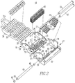
- the sub-assembly 13, which is shown exploded in Figure 2 includes an outer carrier 17 that is firmly secured in the carrier body 3.
- An inner carrier 19 is pivotally mounted to the outer carrier 17 by pivot pins 21 that pass through holes 23 in inner carrier sidewalls 25 and seat in holes 27 in outer carrier sidewalls 29.
- a plurality of contact fingers 31 are pivotally mounted on the inner carrier sidewalls 25 by a contact finger pin 33 that passes through holes 35 in the contact fingers 31 and engage holes 37 in the inner carrier sidewalls 25.
- Two of the contact fingers 31a extend beyond the other contact fingers and bend inward to form arc fingers that, as will be seen, direct arcs formed during current interruption into an arc chute of the circuit breaker.
- Moving contacts 39 are affixed to each of the contact fingers 31.
- the inner carrier 19 has a cross wall 41 extending between the inner carrier sidewalls 25.
- This cross wall 41 has two rows of contact spring pockets 43 on an inner surface in which are seated contact springs 45 that bias the contact fingers 31 against a contact finger stop pin 47 extending between holes 48 the inner carrier side walls 25.
- the contact springs 45 provide contact pressure and adjustment for contact wear as is well known.
- the inner carrier 19 also has an end wall 49 extending between the inner carrier side walls 25.
- This end wall 49 can be integral with or separate from the cross wall 41.
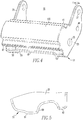
- On the end wall 49 is a cam profile 51 which is made up of two spaced apart cam profile sections 53 at the ends of the end wall 49. This leaves a recess 55 in the end wall between the cam profile sections 53. It will be noted from figure 4 that the cam profile sections 53 extend axially along the end wall 49 a greater distance than the thickness, t, of the inner carrier sidewalls 25.
- the outer carrier 17 has a pair of confronting elongated slots 59 in the outer carrier sidewalls 29.
- a cam follower pin 61 that may have bushings 63 on the ends 65 slides in the elongated slots 59.
- the outer carrier 17 has a base section 67 extending between the outer carrier sidewalls 29 that has a row of cam spring pockets 69 in which are seated a number of cam springs 71.
- a cam spring holder 73 see Figures 2 and 6 , has a number of posts 75 on which the opposite ends of the cam springs 71 seat. Opposite the posts 75 is a partial cylindrical surface 77 that bears against the cam follower pin 61.
- a flange 79 on the base section 67 has a medial rib 81 that has a surface 83 forming a medial abutment while the end of the central rib 81 forms an outer carrier stop 85.
- the end wall 49 on the inner carrier 19 forms an inner carrier stop 87 adjacent the cam sections profile 53, that as will be seen engages the outer carrier stop 85 to accurately fix the withstand position of the inner carrier 19.
- the blow open action of the breaker is created by the cam profile 51 (through the cam sections 53) and the cam follower pin 61 guided by the elongated slots 59 in the outer carrier sidewalls 29.
- the cam follower pin 61 is pressed against cam follower profile sections 53 by the cam springs 71.
- the cam spring holder 73 fit securely to the spring ends by the posts 75, creates a stable seat for the cam springs 71 against the cam follower pin 61.
- a plurality of small springs 71 is used to achieve a compact package and to allow the cam-off force of the assembly to be adjusted by leaving a variable number of spring locations vacant.
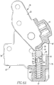
- the cam profile 51 is designed to hold the inner carrier 19 stiffly in place in the withstand position shown in Figure 6 up to the peak force generated by a selected threshold current through the contact fingers 31 and then to rotate abruptly to the blow-open position shown in Figure 6A .
- the steeply-rising portion of the cam profile 51 that creates the high withstand force may include a withstand segment 89 of constant slope (radius rise relative to angular position) to accommodate manufacturing variation without substantial change in peak force. After the peak force in the opening direction, the cam profile 51 falls gently to a lower radius at the open end of travel 91.
- This portion is a rising radius when the inner carrier 19 is resetting and is optimized to minimize dynamic rebound of the inner carrier 19 (and possible re-ignition of an arc) during high current interruption, but allow resetting when the operating mechanism trips as will be discussed.
- the cam follower pin 61 is bearing against the edges of the elongated slots 59 in the outer carrier sidewalls 29. Friction is reduced by the rolling bushings 63 on the ends 65 of the cam follower pin 61.
- the one-piece inner and outer carriers 19, 17 with integral spring pockets 43, 69 increase overall strength and reduce the number of parts, assembly costs and manufacturing variation in the moving contact assembly 1.
- the carriers 17, 19 can be cast, metal-injection molded, or otherwise produced from various magnetic or non-magnetic grades of stainless steel, and hardened as required.
- the one-piece carriers 17, 19 also provide the design flexibility to reinforce areas like the cam profile sections 53 and the outer carrier side walls 29 at the elongated slots 59 with extra width where needed.
- the width of the cam profile sections 53 can be selected with the remainder of the width relieved by the recess 55 for clearance with the cam follower pin 61.
- the selective cam profile section width allows reduction of the contact stress, optimization of manufacturing methods and other desired characteristics of the cam function.
- one or more intermediate bearing ribs such as the rib 81 on the outer carrier 17 can be located with the medial abutment surface 83 in line with the edges with the elongated slots 59 at any location across the outer carrier 17.
- the end of this central rib 81 forms the outer carrier stop 85 against which the inner carrier stop 87 is biased as shown in Figure 6 to fix the withstand position of the inner carrier 19 with accuracy.
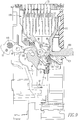
- the moving contact assembly 1 is pivotally mounted in the housing 93 of a power circuit breaker 95 for rotation about bosses 97 on legs 5 between a closed position shown in Figure 7 and an open position shown in Figure 8 .
- the inner carrier 19 is in the withstand position with regard to the outer carrier 17 as seen more clearly in Figure 6 .
- the moving contacts 39 on the contact fingers 31 are pressed by the contact springs 45 against fixed contacts 99 on the monolithic stationary conductor 101, which has a terminal section 103 forming the line terminal of the power circuit breaker 95.
- the lower ends of the contact fingers 31 are connected by flexible shunts, not shown for clarity, that are connected to a load terminal (not shown) located below the line terminal 103. With the power circuit thus completed through the circuit breaker 95 current flows in the directions of the arrows 107.
- the moving contact assembly 1 is connected through a drive link 109 and crank 111 to a pole shaft 113 connecting the moving contact assembly 1 of each of the poles of circuit breaker 95 to an operating mechanism (not shown).
- Rotation of the pole shaft 113 in a clockwise direction either manually or through an operation of a trip unit (not shown) in response to selected amplitude/time characteristics of current, causes the moving contact assembly 1 to be rotated to the open position shown in Figure 2 .
- the moving contacts 39 and fixed contacts 99 separate, an arc is struck, which due to electromagnetic forces is driven up the arc runner section 115 of the monolithic stationary contact 101 and into arc plates 117 of an arc chute 119 where the arc is cooled and extinguished in a known manner.
- Arc gasses generated through vaporization of contact material and gas evolving materials expand up into the arc chute 119 and are exhausted through a vent 121 in the top of housing 93.
- the carrier body 3 has an associated gas shield 123 which can be molded as part of the carrier body 3 or can be attached thereto.
- This gas shield 123 has an outer arcuate surface 125 that is complementary and slides relative to an arcuate surface 127 on the housing 93, as best seen in Figure 8 .
- the gas shield 123 blocks the passage of arc gasses downward for all positions of the moving contact assembly 1.
- the gas shield 123 also has a concave partial cylindrical interior surface 131 and that the cross wall 41 on the outer carrier 19, which incorporates the contact spring pockets 43 has an outer convex partial cylindrical surface 133 that is complementary to and in close proximity to the concave surface 131.
- This arrangement maintains the seal formed by the gas shield 123 even as the inner carrier 19 rotates from the withstand to the blow open position.
- the gas shield 123 is also electrically insulative and along with the insulative member 135 on the front face of the monolithic stationary conductor 101 prevents flashover between the moving contact assembly 1 and the stationary conductor as the inner carrier 19 rotates to the blow open position.
- the pole shaft 113 When the operating mechanism (not shown) responds to the fault current, the pole shaft 113 is rotated to rotate the moving contact assembly 1 to the open position shown in Figure 8 .
- the contact fingers 31 then pivot about the bumper 129 until the inner carrier 19 resets with the cam follower pin 61 engaging the constant sloped portion 89 of the cam profile 51.
Landscapes
- Physics & Mathematics (AREA)
- Electromagnetism (AREA)
- Arc-Extinguishing Devices That Are Switches (AREA)
Claims (4)
- Eine sich bewegende Kontaktanordnung (1) für eine Schaltanordnung (95) für elektrische Leistung, die Folgendes aufweist:einen Trägerkörper (3);einen äußeren Träger (17), der an dem Trägerkörper (3) gesichert ist;einen inneren Träger (19), der in dem äußeren Träger (17) für eine drehbare bzw. schwenkbare Bewegung zwischen einer Halte- bzw. Widerstandsposition und einer aufgesprengten Position bzw. Blow-Open-Position befestigt ist und ein Nockenprofil (51) hat;eine Vielzahl von Kontaktfingern (31), die auf dem inneren Träger (19) befestigt sind;ein Nockennachfolgestift (61);Nockenfedern (71), die gegen den äußeren Träger (17) aufgesetzt sind, die den Nockennachfolgestift (61) gegen das Nockenprofil vorspannen, wobei das Nockenprofil (51) so konfiguriert ist, dass für Strom durch die Vielzahl von Kontaktfingern (31), der geringer ist als ein Schwellenwertstrom, der innere Träger (19) in die Halteposition vorgespannt ist,dadurch gekennzeichnet, dass:die Trägerschenkel (5) den Trägerkörper (3) für eine Drehbewegung zwischen einer geschlossenen Position und einer offenen Position unterstützen;der äußere Träger (17) einen Anschlag (85) des äußeren Trägers hat;der innere Träger (19) einen Anschlag (87) des inneren Trägers hat; unddie Halteposition dadurch eingerichtet wird, dass der Anschlag (87) des inneren Trägers in Eingriff kommt mit dem Anschlag (85) des äußeren Trägers, und für einen Strom durch die Vielzahl von Kontaktfingern (31), der größer ist als der Schwellenwertstrom, sich der innere Träger (19) schlagartig in die aufgesprengte Position dreht.
- Sich bewegende Kontaktanordnung (1) nach Anspruch 1, wobei das Nockenprofil (51) einen Widerstands- bzw. Halteabschnitt (89) hat, der in Eingriff ist mit dem Nockennachfolgestift (61), wenn der innere Träger (19) in der Halteposition ist, wobei der Halteabschnitt (89) des Nockenprofils (51) eine Schräge hat, die konstant ist.
- Sich bewegende Trägeranordnung (1) nach Anspruch 1, wobei der äußere Träger (17) Seitenwände (29) des äußeren Trägers hat und einen Basis- bzw. Grundabschnitt (67) des äußeren Trägers zwischen den Seitenwänden (29) des äußeren Trägers ist und wobei ein äußerer Trägeranschlag (85) auf dem Grundabschnitt (67) des äußeren Trägers ist und wobei der innere Träger (19) Seitenwände (25) des inneren Trägers hat und eine Endwand (49) des inneren Trägers hat, wobei der Anschlag (87) des inneren Trägers auf der Endwand (49) des inneren Trägers ist.
- Sich bewegende Trägeranordnung (1) nach Anspruch 3, wobei der Basisabschnitt (67) des äußeren Trägers Nockenfederaussparungen hat, in denen die Nockenfedern (71) sitzen.
Priority Applications (2)
| Application Number | Priority Date | Filing Date | Title |
|---|---|---|---|
| EP10006917.8A EP2228815B1 (de) | 2005-01-13 | 2006-01-12 | Schutzschalter mit elektrodynamisch öffnendem Kontakt ausgestattet mit einer Lichtbogengasabschirmung |
| EP10006916.0A EP2228814B1 (de) | 2005-01-13 | 2006-01-12 | Schutzschalter mit elektrodynamisch öffnendem Kontakt |
Applications Claiming Priority (2)
| Application Number | Priority Date | Filing Date | Title |
|---|---|---|---|
| US11/035,229 US6977568B1 (en) | 2005-01-13 | 2005-01-13 | Blow open moving contact assembly for electric power switching apparatus with a very high current interruption rating |
| PCT/IB2006/000040 WO2006075232A2 (en) | 2005-01-13 | 2006-01-12 | Blow open moving contact assembly for electric power switching apparatus with a very high current interruption rating |
Related Child Applications (4)
| Application Number | Title | Priority Date | Filing Date |
|---|---|---|---|
| EP10006917.8A Division EP2228815B1 (de) | 2005-01-13 | 2006-01-12 | Schutzschalter mit elektrodynamisch öffnendem Kontakt ausgestattet mit einer Lichtbogengasabschirmung |
| EP10006917.8A Division-Into EP2228815B1 (de) | 2005-01-13 | 2006-01-12 | Schutzschalter mit elektrodynamisch öffnendem Kontakt ausgestattet mit einer Lichtbogengasabschirmung |
| EP10006916.0A Division EP2228814B1 (de) | 2005-01-13 | 2006-01-12 | Schutzschalter mit elektrodynamisch öffnendem Kontakt |
| EP10006916.0A Division-Into EP2228814B1 (de) | 2005-01-13 | 2006-01-12 | Schutzschalter mit elektrodynamisch öffnendem Kontakt |
Publications (2)
| Publication Number | Publication Date |
|---|---|
| EP1836715A2 EP1836715A2 (de) | 2007-09-26 |
| EP1836715B1 true EP1836715B1 (de) | 2017-07-19 |
Family
ID=35465583
Family Applications (3)
| Application Number | Title | Priority Date | Filing Date |
|---|---|---|---|
| EP10006917.8A Expired - Lifetime EP2228815B1 (de) | 2005-01-13 | 2006-01-12 | Schutzschalter mit elektrodynamisch öffnendem Kontakt ausgestattet mit einer Lichtbogengasabschirmung |
| EP10006916.0A Expired - Lifetime EP2228814B1 (de) | 2005-01-13 | 2006-01-12 | Schutzschalter mit elektrodynamisch öffnendem Kontakt |
| EP06710228.5A Expired - Lifetime EP1836715B1 (de) | 2005-01-13 | 2006-01-12 | Elektrodynamisch geöffneten kontaktstruktur für starkstromleistungsschaltergerät |
Family Applications Before (2)
| Application Number | Title | Priority Date | Filing Date |
|---|---|---|---|
| EP10006917.8A Expired - Lifetime EP2228815B1 (de) | 2005-01-13 | 2006-01-12 | Schutzschalter mit elektrodynamisch öffnendem Kontakt ausgestattet mit einer Lichtbogengasabschirmung |
| EP10006916.0A Expired - Lifetime EP2228814B1 (de) | 2005-01-13 | 2006-01-12 | Schutzschalter mit elektrodynamisch öffnendem Kontakt |
Country Status (8)
| Country | Link |
|---|---|
| US (2) | US6977568B1 (de) |
| EP (3) | EP2228815B1 (de) |
| KR (1) | KR101176684B1 (de) |
| CN (1) | CN101103427B (de) |
| AU (1) | AU2006205625B2 (de) |
| BR (1) | BRPI0606253A2 (de) |
| CA (1) | CA2594392C (de) |
| WO (1) | WO2006075232A2 (de) |
Families Citing this family (26)
| Publication number | Priority date | Publication date | Assignee | Title |
|---|---|---|---|---|
| US7518074B2 (en) * | 2006-10-13 | 2009-04-14 | Eaton Corporation | Electrical switching apparatus, and carrier assembly and independent pivot assembly therefor |
| US7474179B2 (en) * | 2006-10-13 | 2009-01-06 | Eaton Corportion | Electrical switching apparatus, and movable contact assembly and contact spring assembly therefor |
| ITBG20060053A1 (it) * | 2006-10-13 | 2008-04-14 | Abb Service Srl | Dispositivo di bassa tensione con equipaggio mobile ad alta tenuta elettrodinamica |
| US7646269B2 (en) * | 2007-03-07 | 2010-01-12 | Eaton Corporation | Electrical switching apparatus, and conductor assembly and shunt assembly therefor |
| US7646270B2 (en) * | 2007-05-04 | 2010-01-12 | Eaton Corporation | Electrical switching apparatus, and yoke assembly and spring assembly therefor |
| US7566840B2 (en) * | 2007-10-04 | 2009-07-28 | General Electric Company | Contact arm mechanism for circuit breaker |
| US7911302B2 (en) * | 2007-11-15 | 2011-03-22 | General Electric Company | Secondary trip system for circuit breaker |
| US8080748B2 (en) * | 2009-04-08 | 2011-12-20 | Eaton Corporation | Circuit breaker with adjustable spring assembly biasing |
| US8183490B2 (en) * | 2009-09-28 | 2012-05-22 | Eaton Corporation | Shield apparatus for circuit breaker |
| US20110309052A1 (en) * | 2010-06-16 | 2011-12-22 | Eaton Corporation | Moving seal with arc creepage surface for an air circuit breaker |
| EP2636052B1 (de) * | 2011-02-08 | 2017-11-29 | Siemens Aktiengesellschaft | Endanschlagvorrichtung, schutzschalter mit endanschlagvorrichtung, und verfahren zu ihrer verwendung |
| KR200460487Y1 (ko) * | 2011-02-22 | 2012-05-24 | 엘에스산전 주식회사 | 소호부를 갖는 배선용 차단기 |
| WO2013119232A1 (en) * | 2012-02-09 | 2013-08-15 | Siemens Aktiengesellschaft | Electrical contact apparatus, circuit breakers, and electrical contact assemblies including cam lever, and methods of operation |
| KR101343185B1 (ko) * | 2012-07-09 | 2013-12-19 | 엘에스산전 주식회사 | 차단기의 가동자 어셈블리 |
| US20140079523A1 (en) * | 2012-09-14 | 2014-03-20 | Caterpillar Inc. | Joint interface for laminate structures |
| KR101516761B1 (ko) * | 2013-12-06 | 2015-05-04 | 현대중공업 주식회사 | 배선용 차단기의 콘택트스프링 보호장치 |
| CN103745896B (zh) * | 2013-12-23 | 2017-01-04 | 上海良信电器股份有限公司 | 一种断路器的动触头系统 |
| US9349560B2 (en) | 2014-02-20 | 2016-05-24 | General Electric Company | Limiter type air circuit breaker with blow open arrangement |
| CN204117869U (zh) * | 2014-09-18 | 2015-01-21 | 浙江正泰电器股份有限公司 | 断路器的触头装置 |
| FR3036841B1 (fr) * | 2015-05-28 | 2017-06-23 | Schneider Electric Ind Sas | Pole mobile et appareil de coupure |
| US9552950B2 (en) * | 2015-06-11 | 2017-01-24 | General Electric Company | Retaining assembly for a circuit breaker contact system |
| US9576753B2 (en) | 2015-06-16 | 2017-02-21 | General Electric Company | Moveable contact arm releases latch plate engagement in a circuit breaker |
| US9805887B2 (en) | 2016-03-16 | 2017-10-31 | Siemens Aktiengesellschaft | Slot motor configuration for high amperage multi-finger circuit breaker |
| CN107680891B (zh) * | 2017-10-31 | 2020-06-30 | 首瑞(天津)电气设备有限公司 | 一种触头灭弧系统、低压断路器及灭弧系统 |
| US10290435B1 (en) * | 2018-03-14 | 2019-05-14 | Eaton Intelligent Power Limited | Magnetic circuit arrangement for an electrical switch |
| CN113725048A (zh) * | 2021-09-18 | 2021-11-30 | 江苏大全凯帆开关股份有限公司 | 一种可消除分闸弹跳的断路器大容量触头灭弧系统 |
Family Cites Families (23)
| Publication number | Priority date | Publication date | Assignee | Title |
|---|---|---|---|---|
| US4916419A (en) * | 1986-10-24 | 1990-04-10 | Square D Company | Circuit breaker contact assembly |
| US4887057A (en) * | 1988-08-01 | 1989-12-12 | Westinghouse Electric Corp. | Cam roll pin assembly |
| US4891618A (en) * | 1988-08-01 | 1990-01-02 | Westinghouse Electric Corp. | Laminated copper assembly |
| US4891617A (en) * | 1988-08-01 | 1990-01-02 | Westinghouse Electric Corp. | Rubber stops in outside poles |
| US5089795A (en) * | 1990-06-29 | 1992-02-18 | General Electric Company | Compact molded case circuit breaker with movable contact arm rebound cushion |
| US5341191A (en) | 1991-10-18 | 1994-08-23 | Eaton Corporation | Molded case current limiting circuit breaker |
| US5247142A (en) | 1992-05-22 | 1993-09-21 | Westinghouse Electric Corp. | Circuit interrupter ARC chute side walls coated with high temperature refractory material |
| US5337031A (en) * | 1993-08-20 | 1994-08-09 | General Electric Company | Cost-efficient industrial-rated molded case breaker |
| US5974874A (en) * | 1993-10-20 | 1999-11-02 | Gas Research Institute | Method for testing gas wells in low pressured gas formations |
| GB9405727D0 (en) * | 1994-03-23 | 1994-05-11 | Gen Electric | Multi-functional isolation housing |
| US5552754A (en) * | 1995-06-05 | 1996-09-03 | Onan Corporation | Catch for electrical contact utilizing electromagnetic forces |
| US5793270A (en) * | 1996-09-03 | 1998-08-11 | Eaton Corporation | Circuit breaker with latch preventing rebound of blow open contact arm |
| IT1289482B1 (it) * | 1996-12-20 | 1998-10-15 | Sace Spa | Interruttore di corrente con contatti movibili |
| US5847629A (en) * | 1997-04-03 | 1998-12-08 | Eaton Corporation | Circuit breaker contact spring subassembly and method and apparatus for making and circuit breaker incorporating same |
| US5912605A (en) * | 1997-11-20 | 1999-06-15 | Eaton Corporation | Circuit breaker with automatic catch to prevent rebound of blow open contact arm |
| US6005206A (en) | 1998-05-07 | 1999-12-21 | Eaton Corporation | Electrical switching apparatus with improved contact arm carrier arrangement |
| US5969314A (en) | 1998-05-07 | 1999-10-19 | Eaton Corporation | Electrical switching apparatus having arc runner integral with stationary arcing contact |
| US6346868B1 (en) * | 2000-03-01 | 2002-02-12 | General Electric Company | Circuit interrupter operating mechanism |
| US6417474B1 (en) | 2001-05-15 | 2002-07-09 | Eaton Corporation | Electrical switching apparatus having an arc runner with an elongated raised ridge |
| US6570116B2 (en) * | 2001-08-16 | 2003-05-27 | Square D Company | Current carrying assembly for a circuit breaker |
| DE20114426U1 (de) * | 2001-08-23 | 2003-01-02 | Siemens AG, 80333 München | Kontaktanordnung für einen elektrischen Schalter |
| DE10149020C1 (de) * | 2001-09-28 | 2003-01-16 | Siemens Ag | Kontaktanordnung für Niederspannungs-Schaltgeräte |
| ITMI20012325A1 (it) * | 2001-11-06 | 2003-05-06 | Abb Service Srl | Interruttore di bassa tensione |
-
2005
- 2005-01-13 US US11/035,229 patent/US6977568B1/en not_active Expired - Lifetime
- 2005-05-31 US US11/139,747 patent/US7034642B1/en not_active Expired - Lifetime
-
2006
- 2006-01-12 WO PCT/IB2006/000040 patent/WO2006075232A2/en not_active Ceased
- 2006-01-12 EP EP10006917.8A patent/EP2228815B1/de not_active Expired - Lifetime
- 2006-01-12 AU AU2006205625A patent/AU2006205625B2/en not_active Ceased
- 2006-01-12 KR KR1020077016055A patent/KR101176684B1/ko not_active Expired - Fee Related
- 2006-01-12 CN CN2006800022841A patent/CN101103427B/zh not_active Expired - Lifetime
- 2006-01-12 EP EP10006916.0A patent/EP2228814B1/de not_active Expired - Lifetime
- 2006-01-12 EP EP06710228.5A patent/EP1836715B1/de not_active Expired - Lifetime
- 2006-01-12 BR BRPI0606253-9A patent/BRPI0606253A2/pt not_active IP Right Cessation
- 2006-01-12 CA CA2594392A patent/CA2594392C/en not_active Expired - Fee Related
Non-Patent Citations (1)
| Title |
|---|
| None * |
Also Published As
| Publication number | Publication date |
|---|---|
| CA2594392C (en) | 2014-09-09 |
| WO2006075232A9 (en) | 2007-08-30 |
| EP2228814B1 (de) | 2016-05-04 |
| CA2594392A1 (en) | 2006-07-20 |
| WO2006075232A2 (en) | 2006-07-20 |
| US7034642B1 (en) | 2006-04-25 |
| CN101103427B (zh) | 2011-05-11 |
| US6977568B1 (en) | 2005-12-20 |
| EP2228814A3 (de) | 2013-02-27 |
| KR101176684B1 (ko) | 2012-08-23 |
| EP2228815B1 (de) | 2018-08-01 |
| AU2006205625A1 (en) | 2006-07-20 |
| WO2006075232A3 (en) | 2007-03-08 |
| CN101103427A (zh) | 2008-01-09 |
| BRPI0606253A2 (pt) | 2009-06-09 |
| EP1836715A2 (de) | 2007-09-26 |
| AU2006205625B2 (en) | 2009-09-17 |
| KR20070103385A (ko) | 2007-10-23 |
| EP2228814A2 (de) | 2010-09-15 |
| EP2228815A3 (de) | 2013-02-27 |
| EP2228815A2 (de) | 2010-09-15 |
Similar Documents
| Publication | Publication Date | Title |
|---|---|---|
| EP1836715B1 (de) | Elektrodynamisch geöffneten kontaktstruktur für starkstromleistungsschaltergerät | |
| CN100552856C (zh) | 用于断路器的接触器组件 | |
| CA1116210A (en) | Current limiting circuit breaker with integral magnetic drive device housing and contact arm stop | |
| KR101823462B1 (ko) | 스위칭 시스템 | |
| US6417474B1 (en) | Electrical switching apparatus having an arc runner with an elongated raised ridge | |
| US5793270A (en) | Circuit breaker with latch preventing rebound of blow open contact arm | |
| US5969314A (en) | Electrical switching apparatus having arc runner integral with stationary arcing contact | |
| US8735758B2 (en) | Circuit breaker having dual arc chamber | |
| US5874699A (en) | Molded case circuit breaker and moving conductor assembly therefor | |
| EP1681693B1 (de) | Einstückiger Festkontakt und strombegrenzender Schalter mit demselben | |
| EP0128676B1 (de) | Überstromschalter | |
| US7199319B1 (en) | Handle assembly having an integral slider therefor and electrical switching apparatus employing the same | |
| CA1331998C (en) | Circuit breaker with low voltage contact structure | |
| EP2831897A1 (de) | Verbesserte doppelbruchkontaktanordnung für gekapselte leistungsschalter | |
| CA2295181A1 (en) | Current limiting circuit breaker operating mechanism including latching system |
Legal Events
| Date | Code | Title | Description |
|---|---|---|---|
| PUAI | Public reference made under article 153(3) epc to a published international application that has entered the european phase |
Free format text: ORIGINAL CODE: 0009012 |
|
| 17P | Request for examination filed |
Effective date: 20070713 |
|
| AK | Designated contracting states |
Kind code of ref document: A2 Designated state(s): AT BE BG CH CY CZ DE DK EE ES FI FR GB GR HU IE IS IT LI LT LU LV MC NL PL PT RO SE SI SK TR |
|
| AX | Request for extension of the european patent |
Extension state: AL BA HR MK YU |
|
| R17D | Deferred search report published (corrected) |
Effective date: 20070830 |
|
| DAX | Request for extension of the european patent (deleted) | ||
| RBV | Designated contracting states (corrected) |
Designated state(s): DE FR GB IT |
|
| 17Q | First examination report despatched |
Effective date: 20091110 |
|
| GRAP | Despatch of communication of intention to grant a patent |
Free format text: ORIGINAL CODE: EPIDOSNIGR1 |
|
| INTG | Intention to grant announced |
Effective date: 20170223 |
|
| GRAS | Grant fee paid |
Free format text: ORIGINAL CODE: EPIDOSNIGR3 |
|
| GRAA | (expected) grant |
Free format text: ORIGINAL CODE: 0009210 |
|
| AK | Designated contracting states |
Kind code of ref document: B1 Designated state(s): DE FR GB IT |
|
| REG | Reference to a national code |
Ref country code: GB Ref legal event code: FG4D |
|
| REG | Reference to a national code |
Ref country code: DE Ref legal event code: R081 Ref document number: 602006053056 Country of ref document: DE Owner name: EATON INTELLIGENT POWER LIMITED, IE Free format text: FORMER OWNER: EATON CORP., CLEVELAND, OHIO, US |
|
| REG | Reference to a national code |
Ref country code: DE Ref legal event code: R096 Ref document number: 602006053056 Country of ref document: DE |
|
| REG | Reference to a national code |
Ref country code: FR Ref legal event code: PLFP Year of fee payment: 13 |
|
| PGFP | Annual fee paid to national office [announced via postgrant information from national office to epo] |
Ref country code: GB Payment date: 20171222 Year of fee payment: 13 |
|
| REG | Reference to a national code |
Ref country code: DE Ref legal event code: R097 Ref document number: 602006053056 Country of ref document: DE |
|
| PLBE | No opposition filed within time limit |
Free format text: ORIGINAL CODE: 0009261 |
|
| STAA | Information on the status of an ep patent application or granted ep patent |
Free format text: STATUS: NO OPPOSITION FILED WITHIN TIME LIMIT |
|
| 26N | No opposition filed |
Effective date: 20180420 |
|
| REG | Reference to a national code |
Ref country code: GB Ref legal event code: 732E Free format text: REGISTERED BETWEEN 20181115 AND 20181130 |
|
| GBPC | Gb: european patent ceased through non-payment of renewal fee |
Effective date: 20190112 |
|
| PG25 | Lapsed in a contracting state [announced via postgrant information from national office to epo] |
Ref country code: GB Free format text: LAPSE BECAUSE OF NON-PAYMENT OF DUE FEES Effective date: 20190112 |
|
| REG | Reference to a national code |
Ref country code: DE Ref legal event code: R082 Ref document number: 602006053056 Country of ref document: DE Representative=s name: WAGNER & GEYER PARTNERSCHAFT MBB PATENT- UND R, DE Ref country code: DE Ref legal event code: R081 Ref document number: 602006053056 Country of ref document: DE Owner name: EATON INTELLIGENT POWER LIMITED, IE Free format text: FORMER OWNER: EATON CORPORATION, CLEVELAND, OHIO, US |
|
| P01 | Opt-out of the competence of the unified patent court (upc) registered |
Effective date: 20230521 |
|
| PGFP | Annual fee paid to national office [announced via postgrant information from national office to epo] |
Ref country code: FR Payment date: 20241219 Year of fee payment: 20 |
|
| PGFP | Annual fee paid to national office [announced via postgrant information from national office to epo] |
Ref country code: DE Payment date: 20241218 Year of fee payment: 20 |
|
| PGFP | Annual fee paid to national office [announced via postgrant information from national office to epo] |
Ref country code: IT Payment date: 20250107 Year of fee payment: 20 |
|
| REG | Reference to a national code |
Ref country code: DE Ref legal event code: R071 Ref document number: 602006053056 Country of ref document: DE |