EP1836475B1 - Sensorsystem für ein in-line-inspektionswerkzeug - Google Patents
Sensorsystem für ein in-line-inspektionswerkzeug Download PDFInfo
- Publication number
- EP1836475B1 EP1836475B1 EP05813631.8A EP05813631A EP1836475B1 EP 1836475 B1 EP1836475 B1 EP 1836475B1 EP 05813631 A EP05813631 A EP 05813631A EP 1836475 B1 EP1836475 B1 EP 1836475B1
- Authority
- EP
- European Patent Office
- Prior art keywords
- sensor
- sensor blocks
- blocks
- inspection tool
- carrier
- Prior art date
- Legal status (The legal status is an assumption and is not a legal conclusion. Google has not performed a legal analysis and makes no representation as to the accuracy of the status listed.)
- Expired - Lifetime
Links
Images




Classifications
-
- F—MECHANICAL ENGINEERING; LIGHTING; HEATING; WEAPONS; BLASTING
- F16—ENGINEERING ELEMENTS AND UNITS; GENERAL MEASURES FOR PRODUCING AND MAINTAINING EFFECTIVE FUNCTIONING OF MACHINES OR INSTALLATIONS; THERMAL INSULATION IN GENERAL
- F16L—PIPES; JOINTS OR FITTINGS FOR PIPES; SUPPORTS FOR PIPES, CABLES OR PROTECTIVE TUBING; MEANS FOR THERMAL INSULATION IN GENERAL
- F16L55/00—Devices or appurtenances for use in, or in connection with, pipes or pipe systems
- F16L55/26—Pigs or moles, i.e. devices movable in a pipe or conduit with or without self-contained propulsion means
- F16L55/28—Constructional aspects
-
- F—MECHANICAL ENGINEERING; LIGHTING; HEATING; WEAPONS; BLASTING
- F16—ENGINEERING ELEMENTS AND UNITS; GENERAL MEASURES FOR PRODUCING AND MAINTAINING EFFECTIVE FUNCTIONING OF MACHINES OR INSTALLATIONS; THERMAL INSULATION IN GENERAL
- F16L—PIPES; JOINTS OR FITTINGS FOR PIPES; SUPPORTS FOR PIPES, CABLES OR PROTECTIVE TUBING; MEANS FOR THERMAL INSULATION IN GENERAL
- F16L55/00—Devices or appurtenances for use in, or in connection with, pipes or pipe systems
- F16L55/26—Pigs or moles, i.e. devices movable in a pipe or conduit with or without self-contained propulsion means
- F16L55/28—Constructional aspects
- F16L55/40—Constructional aspects of the body
- F16L55/44—Constructional aspects of the body expandable
-
- G—PHYSICS
- G01—MEASURING; TESTING
- G01N—INVESTIGATING OR ANALYSING MATERIALS BY DETERMINING THEIR CHEMICAL OR PHYSICAL PROPERTIES
- G01N27/00—Investigating or analysing materials by the use of electric, electrochemical, or magnetic means
- G01N27/72—Investigating or analysing materials by the use of electric, electrochemical, or magnetic means by investigating magnetic variables
- G01N27/82—Investigating or analysing materials by the use of electric, electrochemical, or magnetic means by investigating magnetic variables for investigating the presence of flaws
-
- G—PHYSICS
- G01—MEASURING; TESTING
- G01N—INVESTIGATING OR ANALYSING MATERIALS BY DETERMINING THEIR CHEMICAL OR PHYSICAL PROPERTIES
- G01N27/00—Investigating or analysing materials by the use of electric, electrochemical, or magnetic means
- G01N27/72—Investigating or analysing materials by the use of electric, electrochemical, or magnetic means by investigating magnetic variables
- G01N27/82—Investigating or analysing materials by the use of electric, electrochemical, or magnetic means by investigating magnetic variables for investigating the presence of flaws
- G01N27/83—Investigating or analysing materials by the use of electric, electrochemical, or magnetic means by investigating magnetic variables for investigating the presence of flaws by investigating stray magnetic fields
-
- G—PHYSICS
- G01—MEASURING; TESTING
- G01N—INVESTIGATING OR ANALYSING MATERIALS BY DETERMINING THEIR CHEMICAL OR PHYSICAL PROPERTIES
- G01N27/00—Investigating or analysing materials by the use of electric, electrochemical, or magnetic means
- G01N27/72—Investigating or analysing materials by the use of electric, electrochemical, or magnetic means by investigating magnetic variables
- G01N27/82—Investigating or analysing materials by the use of electric, electrochemical, or magnetic means by investigating magnetic variables for investigating the presence of flaws
- G01N27/90—Investigating or analysing materials by the use of electric, electrochemical, or magnetic means by investigating magnetic variables for investigating the presence of flaws using eddy currents
- G01N27/9013—Arrangements for scanning
- G01N27/902—Arrangements for scanning by moving the sensors
-
- F—MECHANICAL ENGINEERING; LIGHTING; HEATING; WEAPONS; BLASTING
- F16—ENGINEERING ELEMENTS AND UNITS; GENERAL MEASURES FOR PRODUCING AND MAINTAINING EFFECTIVE FUNCTIONING OF MACHINES OR INSTALLATIONS; THERMAL INSULATION IN GENERAL
- F16L—PIPES; JOINTS OR FITTINGS FOR PIPES; SUPPORTS FOR PIPES, CABLES OR PROTECTIVE TUBING; MEANS FOR THERMAL INSULATION IN GENERAL
- F16L2101/00—Uses or applications of pigs or moles
- F16L2101/30—Inspecting, measuring or testing
Definitions
- the present invention relates to a sensor system for an in-line pipe inspection tool.
- Such an in-line pipe inspection tool is also known as a pipeline pig.
- JP 2002 062279 A discloses a leakage flux pig with adjacent sensor blocks arranged in a position shifted relative to each other along a pipe axis direction.
- the pig has permanent magnets defining pole pieces, which are positioned adjacent to the inner wall of the pipe. Those magnets then generate magnetic fields which magnetise the wall of the pipe. Sensors are provided between the magnetic poles, which detect the magnetic flux density at the internal surface of the pipe.
- the magnetic field in the pipe wall is normally constant, but is disturbed by a flux changing feature, such as a defect, weld bead or wall thickness change, and magnetic flux then leaks out of the pipe at such a feature, to be detected by the sensors.
- a flux changing feature such as a defect, weld bead or wall thickness change
- the sensors may be mounted directly to the body of the pig, but it is more usual to mount them on a sensor carrier, which may also carry the pole pieces of the magnetic pole, and which sensor carrier is connected to the body of the pig by a deformable linkage.
- a deformable linkage permits the sensor carrier to move radially, to allow it to pass e.g. a deformation in the pipe.
- the sensor carrier usually forms a body conforming to part of the circumference of a cylinder, and the sensors are mounted on the carrier so as to extend around the circumference of the part-cylinder.
- the sensors sense an arc of the pipeline, at a given position along the pipeline.
- a plurality of such sensor carriers, each with a plurality of sensors are provided on the pipeline pig, so that the whole circumference of the pipeline can be sensed.
- pipeline pigs may be used in pipelines of a range of diameters, and therefore the sensors are normally mounted in sensor blocks, each of which contains one or a plurality of sensors, and which sensor blocks are themselves mounted on supports, often referred to as fingers, which permit the sensor blocks to move radially relative to the body of the pig.
- the radial movement of the sensors permit the sensor blocks to conform to pipelines of different diameters, at least over a range of such diameters.
- the sensor blocks move radially, it will be appreciated that the circumferential distance between the sensor blocks will then change.
- the minimum diameter of the pipeline in which the pig can be used corresponds to that diameter for which the sensor blocks will be in contact with each other, in the circumferential direction.
- the sensor blocks, and hence the sensors of adjacent blocks will move apart. This has the problem that the sensing action may be less than optimal for many pipeline diameters for which the pig is intended for use. Attempts have been made to overcome this problem by having more than one sensor block ring, with the sensor rings being axially displaced along the body of the pig. Note that in such arrangements, although we have referred to the sensor blocks being in a ring, they may be in one or more arcs which need not extend all the way around the body.
- the present invention seeks to provide a sensor arrangement which can adjust to different diameters.
- the present invention proposes that the sensor blocks have a shape such that one axial edge of each sensor block circumferentially overlaps the opposite edge of an adjacent sensor block, at least in the radial innermost position of the radial movement of the sensor blocks and possibly may occur over the whole movement range of the sensor blocks. Effectively, any gap between adjacent sensor blocks, at least in the radial innermost position, has ends which are not aligned, so that one axial end of such a gap is displaced circumferentially relative to the other end.
- the present invention provides an in-line pipe inspection tool having:
- the terms axial, radial, and circumferential are defined relative to the sensor body, which itself is shaped so as to pass down the pipe, and therefore those terms also normally refer to directions within the pipe, at least when the tool is in use.
- the reference to circumferential overlapping refers to overlapping when viewed in the axial direction. It thus does not require part of one sensor block to overlap another in the radial direction.
- each sensor block may support only one sensor, but it is preferable that plurality of the sensors are mounted on each block. It is then possible to mount the sensors so that there is no significant circumferential gap between circumferentially successive sensors, at least over a wide range of possible radial movement of the sensor blocks.
- Each sensor block in the array is shaped that one axial end of each sensor block is circumferentially displaced relative to the other axial end of that sensor. Effectively, the longitudinal axes of the sensor blocks are then inclined relative to the axis of the pig. Then, the circumferential overlapping of adjacent blocks is achieved because the circumferential displacement of the respective axial ends of each sensor means that adjacent sensors have one axial end of one sensor aligned with the opposite axial end of the adjacent sensor.
- an intermediate part of the sensor block is displaced relative to one axial end in the opposite direction from the displacement of the other axial end.
- Such an arrangement will mean that there will be a circumferential overlap between each sensor block and the sensor blocks on either side. This further assists to minimise the effective axial separation of the sensors.
- the sensor blocks may be generally triangular, with alternate sensor blocks having their apexes pointing in opposition axial directions. Note that, with such triangular sensor blocks, the corners of the triangles may be omitted.
- the sensor blocks are "T” shaped with the legs of alternate “T” shaped sensor blocks pointing in opposite axial directions, so that the arms of adjacent "T” shapes overlap in the circumferential direction.
- the sensor blocks will be mounted on a carrier via flexible supports, often known as fingers, which allow the sensor blocks to move radially, but maintain their orientation relative to the axis of the pig.
- the sensor blocks may be mounted on the carrier via sprung or parallelogram linkages.
- the carrier may extend around only a part of the circumference of the pig. It is then possible for there to be multiple sensor arrays, each with its own carrier.
- the mounting of the sensor blocks on the body, or on a carrier will limit the amount of radial movement that is possible. It may be necessary for the pig to accommodate large changes in pipeline diameter. Therefore, the sensors may be mounted on a carrier, the circumferential length of which is variable. Moreover, it is preferable in such an arrangement that the varying of the circumferential length of the carrier causes a variation in the effective radius of curvature of the carrier.
- the carrier itself adapts to different diameters of pipeline, moving the sensors to an appropriate position relative to the pipeline wall.
- the carrier circumferential length there are several different ways of achieving a variation in the carrier circumferential length.
- a carrier consisting of the support parts, to which the sensor blocks are connected, with the support parts being themselves interconnected by a deformable link. Then, the support parts may be moved apart, but the deformable link ensures that they maintain appropriate spacing, thereby controlling the spacing of the sensor blocks.
- the carrier may also comprise plurality of strips which are moveable relative to the other, and act as a backing for the flexible connections. This ensures that the carrier can have sufficient rigidity.
- the carrier needs to be driven to move circumferentially.
- One way to achieve this is by having a pig whose body has moveable parts, to adapt to different diameters. As the parts of the body move the carrier is lengthened or shortened.
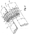
- an in-line pipe inspection tool (pipeline pig) has a body 10 with an array of sensor blocks 12 thereon.
- Each sensor block 12 is connected via a connection 13 to a support 14, which supports are interconnected by a flexible connection 15.
- Each sensor block 12 is pivotally linked to the connection 13, and each connection 13 is pivotally connected to the corresponding support 14.
- the sensor blocks 12 may move radially relative to the body 10 by movement of the connection 13.
- the sensor blocks 12 are able to maintain a fixed orientation relative to the longitudinal axis of the body 10, due to an additional linkage that will be described later.
- Fig. 2 shows two of the sensor blocks 12 in more detail. It can be seen that each sensor block 12 has a first end 12a at one axial end of the sensor block, which end 12a extends generally perpendicular to the longitudinal axis of the body 10. An intermediate part 12b extends at an angle inclined to the ends 12a, a further intermediate part 12c then extends generally parallel to the longitudinal axis of the body 10, and there is a further inclined part 12d, but inclined in the opposite direction to the part 12b, terminating in an end 12e at the opposite axial end of the sensor 12 from the end 12a. It can been seen that the ends 12e are circumferentially offset relative to the ends 12a, because of the inclination of the parts 12b.
- Fig. 2 also illustrates that each sensor block 12 carries 6 sensors 12f, three at each end of the sensor block 12.
- the sensors 12f at one axial end of one sensor block 12 overlap the sensors 12f at the opposite end of the adjacent sensor block 12.
- the spacing between the end most sensors of adjacent sensor blocks is not significantly greater than the spacing of the sensors 12f within a sensor block 12.
- the pig body 10 is deformable, to change its outer diameter.
- two parts 10a, 10b of the body 10 move radially, to create a gap 10c, and in doing so increase the circumference of the body.
- the carriers supporting themselves move circumferentially, so that the array of sensors has an increased circumferential length, but the flexible strip 15 deforms by the same amount between each support 14, thereby ensuring that the spacing between the supports 14, and hence the sensor blocks 12, is maintained uniform.
- Fig. 5 is a similar view to Fig. 4 , but with some of the sensor blocks 12 removed, to enable the supports 14 to be seen more clearly.
- Fig. 5 shows that there may be a further flexible strip 16 at or adjacent to the opposite ends of the supports 14 from the strip 15, to prevent twisting of the supports 14 relative to the longitudinal axis of the body 10.
- Fig. 5 also shows that there may be a mounting strip structure 30 linking the supports 14 to provide the support structure for the one of sensor blocks.
- This strip structure is shown more clearly in Fig. 6 , which is a view similar to Fig. 5 , but with all but the end sensor blocks 12 of the array removed.
- the mounting strip structure 30 comprises two overlapping strip parts 30a, 30b which are fixed to the end supports 14 of the array, and can slip one relative to the other in the circumferential direction.
- the strip parts 30a, 30b provide structural support for the arc of sensor blocks.
- the strips 15, 16 then ensure even circumferential spacing between the supports 14.
- Fig. 6 also shows that there may be a further flexible linkage 17 between the sensor blocks 12 and the support 14, the purpose of which is to provide, together with the link 13, a parallelogram linkage between the supports 14 and the sensor blocks 12, so that the sensor blocks 12 maintain the correct orientation relative to the longitudinal axis of the body 10.
- the linkages 17 are connected between the respective sensor blocks 12 and the supports 14, for the sensor blocks shown in Fig. 6 , they will be connected between the sensor blocks 12 and the support 14 for the other sensor blocks, which are omitted from the view of Fig. 6 , since those supports 14 will move relative to the body.
- the body 10 has parts which move radially to increase the circumference of the body. This is illustrated in more detail in Figs. 7 and 8 .
- the body 10 has 5 body parts 10a, 10b, 10d, 10e and 10f, mounted on a central core 40, with the body parts, 10a, 10b, 10d, 10e and 10f being movable radially relative to that core 40 to the position shown in Fig. 8 .
- the body parts 10a, 10b, 10d, 10e and 10f of the body 10 need not extend over the full axial length of the body 10, so that there may be another part 42 of the body with no such radial movement.
- the body parts 10a, 10b, 10d, 10e and 10f can move radially by different amounts along their length.
- the body parts can then adopt a conical shape.
- it is still desirable that the arc of sensor blocks remains uniform and aligned with the wall of the pipe, and this can be achieved as a result of pivots at the mounting points of the sensor block assembly.
- the sensor blocks have a convoluted shape in which the first axial end 12a is circumferentially offset relative to the opposite axial end 12e.
- the present invention is not limited to such a block arrangement.
- Figs. 9 to 11 show alternative configurations for the sensor blocks.
- the sensor block 50 has a general triangle shape, although the corners of the angles have been removed so they are not needed).
- the sensor blocks 50 have an edge 51 which is generally perpendicular to the axis of the body 10, hence to the point, an inclined sides 52.
- Alternate sensor blocks 50 point in opposite directions, so that the edges 52 of adjacent sensor blocks 50 are parallel.
- narrow gaps 53 are defined between adjacent sensor blocks, which gaps 53 are inclined to both the axial and circumferential directions.
- sensors 54 are mounted on the sensor blocks 50, arranged along the inclined edges 52.
- the edge 50 of one sensor block overlaps, in the circumferential direction, the edge 50 of the adjacent sensor block.
- the circumferential spacing of at least one sensor in one block relative to at least one sensor in the adjacent block is not greater than the spacing between the sensors within each block.
- sensing can be carried out over the four circumferential extent of the sensor block array. This is true even when the sensor blocks over part to the position shown in Fig. 9b .
- the width of the gaps 53 has increased, and indeed in the position shown in Fig. 9b the sensor blocks 50 have moved so that their edges 51 no longer overlap.
- the gap 56 between the end most sensors of adjacent sensor blocks is not significantly greater than the gap 56 between adjacent sensors within a block, so that substantially uniform sensing can still be achieved when the sensor blocks 50 are in the position shown in 9b, corresponding to the greater remedial position than that shown in Fig. 9a .
- Figs. 10a and 10b illustrate another sensor arrangement, in which the sensor blocks 60 are generally T-shaped, with the legs 61 of adjacent blocks 60 extending in opposite axial direction.
- the arms 62 of the sensor block 60 overlap in the circumferential direction, when the sensor blocks 60 are in the inner most radial position.
- the gap 63 between adjacent sensor blocks is convoluted, with one axial end of each gap 63 being displaced relative to the other axial end.
- sensors 64 are mounted on the arms 62 and the leg 61 of the sensor block 60.
- the circumferential spacing between at least one sensor of each adjacent sensor blocks is less than the circumferential spacing of the sensors within each sensor block.
- the circumferential separation 65 between the end most sensor 64 of adjacent sensor blocks 60 is not significantly greater than the spacing 66 between adjacent sensors within the sensor block.
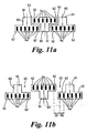
- Figs. 11a and 11b illustrate a modification of the arrangement of Figs. 10a and 10b , in which the sensors 64 are mounted only on the arms of the "T-shaped" sensor blocks 60.
- the arrangement of Figs. 11a and 11b is otherwise the same as that of Figs. 10a and 10b , and will not be described in further detail.
- the same reference numerals are used to indicate corresponding parts.
Landscapes
- Chemical & Material Sciences (AREA)
- Engineering & Computer Science (AREA)
- General Engineering & Computer Science (AREA)
- Health & Medical Sciences (AREA)
- Immunology (AREA)
- Life Sciences & Earth Sciences (AREA)
- Analytical Chemistry (AREA)
- Biochemistry (AREA)
- General Health & Medical Sciences (AREA)
- General Physics & Mathematics (AREA)
- Physics & Mathematics (AREA)
- Pathology (AREA)
- Electrochemistry (AREA)
- Chemical Kinetics & Catalysis (AREA)
- Combustion & Propulsion (AREA)
- Mechanical Engineering (AREA)
- Investigating Or Analyzing Materials By The Use Of Magnetic Means (AREA)
Claims (9)
- Innenliegendes Rohrinspektionsgerät, das Folgendes umfasst:einen Körper (10);Magneten, die in den Körper eingebaut sind, um in einem Rohr ein Magnetfeld zu generieren; undmehrere Sensorblöcke (12), wobei jeder Sensorblock mindestens einen Sensor (12f) zum Erfassen des Magnetfelds trägt;wobei die Sensorblöcke (12) aneinander angrenzend in einer Anordnung angeordnet sind, die Anordnung sich um mindestens einen Teil des Umfangs des Körpers erstreckt, jeder Sensorblock (12) in einer radialen Richtung in Bezug auf den Körper beweglich ist und jeder Sensorblock in der Anordnung so geformt ist, dass eine axiale Kante eines jeden Sensorblocks umlaufend die gegenüberliegende axiale Kante eines angrenzenden Sensorblocks überlappt, zumindest wenn die Sensorblöcke sich in einer radial völlig innenliegenden Position befinden, und dadurch gekennzeichnet, dass ein axiales Ende (12a) eines jeden der Sensorblöcke (12) umlaufend in Bezug auf das andere axiale Ende (12e) des entsprechenden der Sensorblöcke (12) versetzt ist.
- Innenliegendes Rohrinspektionsgerät nach Anspruch 1, wobei jeder der Sensorblöcke (12) mehrere Sensoren (12f) trägt.
- Innenliegendes Rohrinspektionsgerät nach einem der vorstehenden Ansprüche, das weiterhin einen Träger (14, 15) umfasst, wobei die Sensorblöcke (12) mit dem Träger (14, 15) durch ein flexibles Gestänge (13) verbunden sind.
- Innenliegendes Rohrinspektionsgerät nach einem der vorstehenden Ansprüche, wobei die Anordnung einen Träger (14, 15) umfasst, an dem die Sensorblöcke (12) angebaut sind, wobei der Träger eine variable umlaufende Länge aufweist, so dass der umlaufende Abstand zwischen den Sensorblöcken (12) verändert werden kann.
- Innenliegendes Rohrinspektionsgerät nach Anspruch 4, wobei der Träger (14, 15) mehrere Trageteile (14) umfasst, die durch eine verformbare Verbindung (15) miteinander verbunden sind, und die Sensorblöcke (12) an den Trageteilen (14) angebaut sind.
- Innenliegendes Rohrinspektionsgerät nach Anspruch 4 oder 5, wobei der Körper (10) mehrere bewegliche Teile (10a, 10b) umfasst und die Bewegung der Teile die umlaufende Länge des Trägers (14, 15) auf die Weise verändert.
- Innenliegendes Rohrinspektionsgerät nach einem der vorstehenden Ansprüche, wobei ein Zwischenteil (12c) eines jeden der Sensorblöcke (12) umlaufend in Bezug auf das eine axiale Ende (12a) versetzt ist, und zwar in der entgegengesetzten Richtung zum Versatz des Zwischenteils (12c) in Bezug auf das andere axiale Ende (12d).
- Innenliegendes Rohrinspektionsgerät nach einem der Ansprüche 1 bis 6, wobei die Sensorblöcke (12) dreieckig sind, wobei die Scheitelpunkte von alternierenden Sensorblöcken (12) in entgegengesetzte axiale Richtungen weisen.
- Innenliegendes Rohrinspektionsgerät nach einem der Ansprüche 1 bis 6, wobei die Sensorblöcke (12) T-förmig sind, wobei die linke Seite des T von alternierenden Sensorblöcken (12) in entgegengesetzte axiale Richtungen weist.
Applications Claiming Priority (2)
| Application Number | Priority Date | Filing Date | Title |
|---|---|---|---|
| GBGB0428127.5A GB0428127D0 (en) | 2004-12-22 | 2004-12-22 | A sensor system for an in-line inspection tool |
| PCT/GB2005/004657 WO2006067369A1 (en) | 2004-12-22 | 2005-12-05 | A sensor system for an in-line inspection tool |
Publications (2)
| Publication Number | Publication Date |
|---|---|
| EP1836475A1 EP1836475A1 (de) | 2007-09-26 |
| EP1836475B1 true EP1836475B1 (de) | 2015-09-30 |
Family
ID=34113084
Family Applications (1)
| Application Number | Title | Priority Date | Filing Date |
|---|---|---|---|
| EP05813631.8A Expired - Lifetime EP1836475B1 (de) | 2004-12-22 | 2005-12-05 | Sensorsystem für ein in-line-inspektionswerkzeug |
Country Status (5)
| Country | Link |
|---|---|
| US (1) | US8373411B2 (de) |
| EP (1) | EP1836475B1 (de) |
| CA (1) | CA2591677C (de) |
| GB (2) | GB0428127D0 (de) |
| WO (1) | WO2006067369A1 (de) |
Families Citing this family (26)
| Publication number | Priority date | Publication date | Assignee | Title |
|---|---|---|---|---|
| WO2008040312A1 (de) * | 2006-09-28 | 2008-04-10 | Prüftechnik Dieter Busch AG | Magnetische streufluss-testvorrichtung für rohrförmige prüflinge |
| US8020460B1 (en) * | 2008-02-11 | 2011-09-20 | Hoyt Philip M | Sensor housing and mount for in-line inspection tool |
| AU2011313872B2 (en) * | 2010-10-14 | 2015-01-22 | Halliburton Energy Services, Inc. | Method for measuring remote field eddy current thickness in multiple tubular configuration |
| EP2527710A1 (de) * | 2011-05-26 | 2012-11-28 | Pii Limited | Vorrichtung zur Pipeline-Inspektion und Verfahren zur Pipeline-Inspektion |
| CN103575800B (zh) * | 2012-07-20 | 2016-08-03 | 中国石油化工股份有限公司 | 一种管道漏磁检测器探头支架 |
| CN103592364B (zh) * | 2013-11-23 | 2016-05-18 | 清华大学 | 浮动式管道内漏磁检测装置的手指探头单元 |
| CN104007174A (zh) * | 2014-06-12 | 2014-08-27 | 北京华航无线电测量研究所 | 一种长输油气管道内检测用传感器阵列 |
| GB2538517A (en) * | 2015-05-19 | 2016-11-23 | I2I Pipelines Ltd | Improved pipe pig |
| US10458822B2 (en) | 2016-07-11 | 2019-10-29 | Entegra LLP | Dynamic spacer for a smart pipeline inspection gauge |
| US11307063B2 (en) | 2016-12-23 | 2022-04-19 | Gtc Law Group Pc & Affiliates | Inspection robot for horizontal tube inspection having vertically positionable sensor carriage |
| US12358141B2 (en) | 2016-12-23 | 2025-07-15 | Gecko Robotics, Inc. | Systems, methods, and apparatus for providing interactive inspection map for inspection robot |
| EP3974823B1 (de) | 2016-12-23 | 2024-03-06 | Gecko Robotics, Inc. | Prüfroboter |
| US11673272B2 (en) | 2016-12-23 | 2023-06-13 | Gecko Robotics, Inc. | Inspection robot with stability assist device |
| US12162160B2 (en) | 2016-12-23 | 2024-12-10 | Gecko Robotics, Inc. | System, apparatus and method for improved location identification with prism |
| DE102019211479A1 (de) * | 2019-07-31 | 2021-02-04 | Institut Dr. Foerster Gmbh & Co. Kg | Prüfkopfanordnung für eine Prüfanlage sowie Prüfanlage |
| US11579119B1 (en) * | 2019-11-22 | 2023-02-14 | Cypress In-Line Inspection, LLC | Radial springs on sensor arms of pipeline inspection tool |
| TWI911233B (zh) * | 2020-06-18 | 2026-01-11 | 泰商榮龍工程設備服務有限公司 | 一用於偵測一表面之不平整度之感測器模組,一具有該模組之裝置,以及一使用該感測器模組,以偵測一表面其不平整度之方法 |
| CN112083061A (zh) * | 2020-09-28 | 2020-12-15 | 李冰梅 | Z型探头及管道漏磁检测器 |
| CN112505136B (zh) * | 2020-11-27 | 2023-06-30 | 陕西工业职业技术学院 | 一种基于磁记忆的曲面检测装置及其检测方法 |
| US11865698B2 (en) | 2021-04-20 | 2024-01-09 | Gecko Robotics, Inc. | Inspection robot with removeable interface plates and method for configuring payload interfaces |
| WO2022226222A1 (en) | 2021-04-22 | 2022-10-27 | Gecko Robotics, Inc. | Systems, methods, and apparatus for ultra-sonic inspection of a surface |
| US12566158B2 (en) | 2021-04-22 | 2026-03-03 | Gecko Robotics, Inc. | Robotic systems for ultrasonic surface inspection using shaped elements |
| CN115728379A (zh) * | 2021-08-30 | 2023-03-03 | 中国石油管道局工程有限公司 | 高密度异形探头电路板结构 |
| US20230176015A1 (en) * | 2021-12-06 | 2023-06-08 | King Fahd University Of Petroleum And Minerals | Advanced caliper for a pipe and method of use |
| WO2024097795A2 (en) * | 2022-11-01 | 2024-05-10 | Gecko Robotics, Inc. | Inspection robot with profile adapting sled, couplant reduction film and transducer pod for thick assets |
| US20250052718A1 (en) * | 2023-08-08 | 2025-02-13 | Entegra LLP | Circumferential magnetizer for a pipeline inspection gauge |
Citations (1)
| Publication number | Priority date | Publication date | Assignee | Title |
|---|---|---|---|---|
| JP2002062279A (ja) * | 2000-08-22 | 2002-02-28 | Tokyo Gas Co Ltd | 漏洩磁束ピグ |
Family Cites Families (11)
| Publication number | Priority date | Publication date | Assignee | Title |
|---|---|---|---|---|
| GB1535252A (en) * | 1976-04-09 | 1978-12-13 | British Gas Corp | Pipeline inspection vehicles |
| GB2044459B (en) | 1979-03-16 | 1983-10-26 | British Gas Corp | Velocity correction arrangement for non-destructive testing apparatus |
| DD301770A9 (de) | 1987-01-07 | 1993-11-25 | Mineraloelverbundleitung Schwe | Diagnosemolch zur ermittlung von schadstellen an rohrleitungswaenden nach dem wirbelstromverfahren |
| US5115196A (en) * | 1988-06-01 | 1992-05-19 | Atlantic Richfield Company | Girth weld detection system for pipeline survey pig |
| EP0624793A1 (de) * | 1993-05-03 | 1994-11-17 | Tuboscope Vetco (Deutschland) Gmbh | Verfahren und Gerät zur Ermittlung von magnetischen Unstetigkeiten in einer Probe aus magnetisierbarem Material |
| DE20011223U1 (de) * | 2000-06-26 | 2000-10-05 | Kindler, Ulrich, Prof. Dr.-Ing., 22143 Hamburg | Vorrichtung zur berührungslosen Wegmessung, insbesondere zur Stellungs- und Bewegungserfassung |
| US6640655B1 (en) * | 2000-10-03 | 2003-11-04 | Varco I/P, Inc. | Self tracking sensor suspension mechanism |
| RU2204113C1 (ru) * | 2002-03-28 | 2003-05-10 | ЗАО "Нефтегазкомплектсервис" | Носитель датчиков для внутритрубного инспекционного снаряда (варианты) |
| US6931748B2 (en) | 2002-04-05 | 2005-08-23 | Varco I/P, Inc. | Riser and tubular inspection systems |
| US6847207B1 (en) * | 2004-04-15 | 2005-01-25 | Tdw Delaware, Inc. | ID-OD discrimination sensor concept for a magnetic flux leakage inspection tool |
| US7997139B2 (en) * | 2007-12-03 | 2011-08-16 | Fbs, Inc. | Guided wave pipeline inspection system and method with enhanced natural focusing techniques |
-
2004
- 2004-12-22 GB GBGB0428127.5A patent/GB0428127D0/en not_active Ceased
-
2005
- 2005-12-05 CA CA2591677A patent/CA2591677C/en not_active Expired - Fee Related
- 2005-12-05 WO PCT/GB2005/004657 patent/WO2006067369A1/en not_active Ceased
- 2005-12-05 GB GB0524776A patent/GB2421777B/en not_active Expired - Fee Related
- 2005-12-05 US US11/722,482 patent/US8373411B2/en not_active Expired - Fee Related
- 2005-12-05 EP EP05813631.8A patent/EP1836475B1/de not_active Expired - Lifetime
Patent Citations (1)
| Publication number | Priority date | Publication date | Assignee | Title |
|---|---|---|---|---|
| JP2002062279A (ja) * | 2000-08-22 | 2002-02-28 | Tokyo Gas Co Ltd | 漏洩磁束ピグ |
Non-Patent Citations (1)
| Title |
|---|
| DATABASE WPI Week 200238, Derwent World Patents Index; AN 2002-346629 * |
Also Published As
| Publication number | Publication date |
|---|---|
| GB0524776D0 (en) | 2006-01-11 |
| GB2421777B (en) | 2007-05-02 |
| US8373411B2 (en) | 2013-02-12 |
| WO2006067369A1 (en) | 2006-06-29 |
| CA2591677A1 (en) | 2006-06-29 |
| EP1836475A1 (de) | 2007-09-26 |
| US20100060273A1 (en) | 2010-03-11 |
| GB2421777A (en) | 2006-07-05 |
| GB0428127D0 (en) | 2005-01-26 |
| CA2591677C (en) | 2016-06-28 |
Similar Documents
| Publication | Publication Date | Title |
|---|---|---|
| CA2591677C (en) | A sensor system for an in-line inspection tool | |
| CA2306299C (en) | Device for moving a pig through a conduit, such as a pipeline, and sealing means for a device of this type | |
| EP2527708A1 (de) | Vorrichtung zur Inspektion von Pipelines und Pipeline-Inspektionsverfahren | |
| CA2854486C (en) | Lateral buckling mitigation apparatus, methods and systems for use with subsea conduits | |
| CA2327990C (en) | Pipeline pigs | |
| KR102153521B1 (ko) | 실링 성능을 향상시킨 배관 검사 장치 | |
| EP1453170A2 (de) | Vorrichtung zum Verlegen von Leitungselementen | |
| US20120325004A1 (en) | Apparatus for pipeline inspection and method of pipeline inspection | |
| GB2432894A (en) | A sensor system for an in-line inspection tool | |
| US8573470B2 (en) | Welding system | |
| CN112976628A (zh) | 胎圈保持构件、胎圈保持设备与胎圈操纵组件 | |
| EP3953700B1 (de) | Rohrleitungswerkzeug mit verbundmagnetfeld zur inline-inspektion | |
| JP3474493B2 (ja) | シリンダ装置 | |
| US11635142B2 (en) | Dual barrier seal | |
| WO2018092893A1 (ja) | エルボ付き伸縮管継手 | |
| CN110064679B (zh) | 一种用于套筒的同步涨缩导向环 | |
| JPH08338571A (ja) | 二重異形管 | |
| JP4069304B2 (ja) | ベローズ継手 | |
| TW202521449A (zh) | 彎曲輸送機用滾輪、彎曲輸送機以及彎曲皮帶 | |
| KR20240146443A (ko) | 배관 검사 장치 | |
| JP2000180571A (ja) | 核融合装置用コイル支持装置 | |
| JPH09210967A (ja) | 探傷装置 | |
| JPH062223U (ja) | 調芯器 |
Legal Events
| Date | Code | Title | Description |
|---|---|---|---|
| PUAI | Public reference made under article 153(3) epc to a published international application that has entered the european phase |
Free format text: ORIGINAL CODE: 0009012 |
|
| 17P | Request for examination filed |
Effective date: 20070625 |
|
| AK | Designated contracting states |
Kind code of ref document: A1 Designated state(s): AT BE BG CH CY CZ DE DK EE ES FI FR GB GR HU IE IS IT LI LT LU LV MC NL PL PT RO SE SI SK TR |
|
| DAX | Request for extension of the european patent (deleted) | ||
| 17Q | First examination report despatched |
Effective date: 20140605 |
|
| GRAP | Despatch of communication of intention to grant a patent |
Free format text: ORIGINAL CODE: EPIDOSNIGR1 |
|
| INTG | Intention to grant announced |
Effective date: 20150513 |
|
| GRAS | Grant fee paid |
Free format text: ORIGINAL CODE: EPIDOSNIGR3 |
|
| GRAA | (expected) grant |
Free format text: ORIGINAL CODE: 0009210 |
|
| AK | Designated contracting states |
Kind code of ref document: B1 Designated state(s): AT BE BG CH CY CZ DE DK EE ES FI FR GB GR HU IE IS IT LI LT LU LV MC NL PL PT RO SE SI SK TR |
|
| REG | Reference to a national code |
Ref country code: CH Ref legal event code: EP Ref country code: GB Ref legal event code: FG4D |
|
| REG | Reference to a national code |
Ref country code: AT Ref legal event code: REF Ref document number: 752704 Country of ref document: AT Kind code of ref document: T Effective date: 20151015 |
|
| REG | Reference to a national code |
Ref country code: IE Ref legal event code: FG4D |
|
| REG | Reference to a national code |
Ref country code: DE Ref legal event code: R096 Ref document number: 602005047620 Country of ref document: DE |
|
| REG | Reference to a national code |
Ref country code: FR Ref legal event code: PLFP Year of fee payment: 11 |
|
| PG25 | Lapsed in a contracting state [announced via postgrant information from national office to epo] |
Ref country code: FI Free format text: LAPSE BECAUSE OF FAILURE TO SUBMIT A TRANSLATION OF THE DESCRIPTION OR TO PAY THE FEE WITHIN THE PRESCRIBED TIME-LIMIT Effective date: 20150930 Ref country code: LV Free format text: LAPSE BECAUSE OF FAILURE TO SUBMIT A TRANSLATION OF THE DESCRIPTION OR TO PAY THE FEE WITHIN THE PRESCRIBED TIME-LIMIT Effective date: 20150930 Ref country code: LT Free format text: LAPSE BECAUSE OF FAILURE TO SUBMIT A TRANSLATION OF THE DESCRIPTION OR TO PAY THE FEE WITHIN THE PRESCRIBED TIME-LIMIT Effective date: 20150930 Ref country code: GR Free format text: LAPSE BECAUSE OF FAILURE TO SUBMIT A TRANSLATION OF THE DESCRIPTION OR TO PAY THE FEE WITHIN THE PRESCRIBED TIME-LIMIT Effective date: 20151231 |
|
| REG | Reference to a national code |
Ref country code: LT Ref legal event code: MG4D |
|
| REG | Reference to a national code |
Ref country code: AT Ref legal event code: MK05 Ref document number: 752704 Country of ref document: AT Kind code of ref document: T Effective date: 20150930 |
|
| REG | Reference to a national code |
Ref country code: NL Ref legal event code: FP |
|
| PG25 | Lapsed in a contracting state [announced via postgrant information from national office to epo] |
Ref country code: SE Free format text: LAPSE BECAUSE OF FAILURE TO SUBMIT A TRANSLATION OF THE DESCRIPTION OR TO PAY THE FEE WITHIN THE PRESCRIBED TIME-LIMIT Effective date: 20150930 |
|
| PGFP | Annual fee paid to national office [announced via postgrant information from national office to epo] |
Ref country code: NL Payment date: 20151226 Year of fee payment: 11 Ref country code: FR Payment date: 20151217 Year of fee payment: 11 |
|
| PG25 | Lapsed in a contracting state [announced via postgrant information from national office to epo] |
Ref country code: CZ Free format text: LAPSE BECAUSE OF FAILURE TO SUBMIT A TRANSLATION OF THE DESCRIPTION OR TO PAY THE FEE WITHIN THE PRESCRIBED TIME-LIMIT Effective date: 20150930 Ref country code: IS Free format text: LAPSE BECAUSE OF FAILURE TO SUBMIT A TRANSLATION OF THE DESCRIPTION OR TO PAY THE FEE WITHIN THE PRESCRIBED TIME-LIMIT Effective date: 20160130 Ref country code: SK Free format text: LAPSE BECAUSE OF FAILURE TO SUBMIT A TRANSLATION OF THE DESCRIPTION OR TO PAY THE FEE WITHIN THE PRESCRIBED TIME-LIMIT Effective date: 20150930 Ref country code: ES Free format text: LAPSE BECAUSE OF FAILURE TO SUBMIT A TRANSLATION OF THE DESCRIPTION OR TO PAY THE FEE WITHIN THE PRESCRIBED TIME-LIMIT Effective date: 20150930 Ref country code: EE Free format text: LAPSE BECAUSE OF FAILURE TO SUBMIT A TRANSLATION OF THE DESCRIPTION OR TO PAY THE FEE WITHIN THE PRESCRIBED TIME-LIMIT Effective date: 20150930 |
|
| PG25 | Lapsed in a contracting state [announced via postgrant information from national office to epo] |
Ref country code: RO Free format text: LAPSE BECAUSE OF FAILURE TO SUBMIT A TRANSLATION OF THE DESCRIPTION OR TO PAY THE FEE WITHIN THE PRESCRIBED TIME-LIMIT Effective date: 20150930 Ref country code: PL Free format text: LAPSE BECAUSE OF FAILURE TO SUBMIT A TRANSLATION OF THE DESCRIPTION OR TO PAY THE FEE WITHIN THE PRESCRIBED TIME-LIMIT Effective date: 20150930 Ref country code: AT Free format text: LAPSE BECAUSE OF FAILURE TO SUBMIT A TRANSLATION OF THE DESCRIPTION OR TO PAY THE FEE WITHIN THE PRESCRIBED TIME-LIMIT Effective date: 20150930 Ref country code: PT Free format text: LAPSE BECAUSE OF FAILURE TO SUBMIT A TRANSLATION OF THE DESCRIPTION OR TO PAY THE FEE WITHIN THE PRESCRIBED TIME-LIMIT Effective date: 20160201 Ref country code: BE Free format text: LAPSE BECAUSE OF NON-PAYMENT OF DUE FEES Effective date: 20151231 |
|
| REG | Reference to a national code |
Ref country code: DE Ref legal event code: R097 Ref document number: 602005047620 Country of ref document: DE |
|
| PG25 | Lapsed in a contracting state [announced via postgrant information from national office to epo] |
Ref country code: MC Free format text: LAPSE BECAUSE OF FAILURE TO SUBMIT A TRANSLATION OF THE DESCRIPTION OR TO PAY THE FEE WITHIN THE PRESCRIBED TIME-LIMIT Effective date: 20150930 Ref country code: LU Free format text: LAPSE BECAUSE OF FAILURE TO SUBMIT A TRANSLATION OF THE DESCRIPTION OR TO PAY THE FEE WITHIN THE PRESCRIBED TIME-LIMIT Effective date: 20151205 |
|
| REG | Reference to a national code |
Ref country code: CH Ref legal event code: PL |
|
| PLBE | No opposition filed within time limit |
Free format text: ORIGINAL CODE: 0009261 |
|
| STAA | Information on the status of an ep patent application or granted ep patent |
Free format text: STATUS: NO OPPOSITION FILED WITHIN TIME LIMIT |
|
| PG25 | Lapsed in a contracting state [announced via postgrant information from national office to epo] |
Ref country code: DK Free format text: LAPSE BECAUSE OF FAILURE TO SUBMIT A TRANSLATION OF THE DESCRIPTION OR TO PAY THE FEE WITHIN THE PRESCRIBED TIME-LIMIT Effective date: 20150930 |
|
| 26N | No opposition filed |
Effective date: 20160701 |
|
| REG | Reference to a national code |
Ref country code: IE Ref legal event code: MM4A |
|
| PG25 | Lapsed in a contracting state [announced via postgrant information from national office to epo] |
Ref country code: CH Free format text: LAPSE BECAUSE OF NON-PAYMENT OF DUE FEES Effective date: 20151231 Ref country code: IE Free format text: LAPSE BECAUSE OF NON-PAYMENT OF DUE FEES Effective date: 20151205 Ref country code: LI Free format text: LAPSE BECAUSE OF NON-PAYMENT OF DUE FEES Effective date: 20151231 |
|
| PG25 | Lapsed in a contracting state [announced via postgrant information from national office to epo] |
Ref country code: SI Free format text: LAPSE BECAUSE OF FAILURE TO SUBMIT A TRANSLATION OF THE DESCRIPTION OR TO PAY THE FEE WITHIN THE PRESCRIBED TIME-LIMIT Effective date: 20150930 |
|
| PG25 | Lapsed in a contracting state [announced via postgrant information from national office to epo] |
Ref country code: BE Free format text: LAPSE BECAUSE OF FAILURE TO SUBMIT A TRANSLATION OF THE DESCRIPTION OR TO PAY THE FEE WITHIN THE PRESCRIBED TIME-LIMIT Effective date: 20150930 |
|
| PG25 | Lapsed in a contracting state [announced via postgrant information from national office to epo] |
Ref country code: IT Free format text: LAPSE BECAUSE OF NON-PAYMENT OF DUE FEES Effective date: 20151205 |
|
| PG25 | Lapsed in a contracting state [announced via postgrant information from national office to epo] |
Ref country code: BG Free format text: LAPSE BECAUSE OF FAILURE TO SUBMIT A TRANSLATION OF THE DESCRIPTION OR TO PAY THE FEE WITHIN THE PRESCRIBED TIME-LIMIT Effective date: 20150930 Ref country code: HU Free format text: LAPSE BECAUSE OF FAILURE TO SUBMIT A TRANSLATION OF THE DESCRIPTION OR TO PAY THE FEE WITHIN THE PRESCRIBED TIME-LIMIT; INVALID AB INITIO Effective date: 20051205 |
|
| PG25 | Lapsed in a contracting state [announced via postgrant information from national office to epo] |
Ref country code: CY Free format text: LAPSE BECAUSE OF FAILURE TO SUBMIT A TRANSLATION OF THE DESCRIPTION OR TO PAY THE FEE WITHIN THE PRESCRIBED TIME-LIMIT Effective date: 20150930 |
|
| REG | Reference to a national code |
Ref country code: NL Ref legal event code: MM Effective date: 20170101 |
|
| PG25 | Lapsed in a contracting state [announced via postgrant information from national office to epo] |
Ref country code: IT Free format text: LAPSE BECAUSE OF NON-PAYMENT OF DUE FEES Effective date: 20151205 Ref country code: TR Free format text: LAPSE BECAUSE OF FAILURE TO SUBMIT A TRANSLATION OF THE DESCRIPTION OR TO PAY THE FEE WITHIN THE PRESCRIBED TIME-LIMIT Effective date: 20150930 |
|
| PGFP | Annual fee paid to national office [announced via postgrant information from national office to epo] |
Ref country code: IT Payment date: 20151222 Year of fee payment: 11 |
|
| PGRI | Patent reinstated in contracting state [announced from national office to epo] |
Ref country code: IT Effective date: 20170710 |
|
| PG25 | Lapsed in a contracting state [announced via postgrant information from national office to epo] |
Ref country code: NL Free format text: LAPSE BECAUSE OF NON-PAYMENT OF DUE FEES Effective date: 20170101 |
|
| REG | Reference to a national code |
Ref country code: FR Ref legal event code: ST Effective date: 20170831 |
|
| PG25 | Lapsed in a contracting state [announced via postgrant information from national office to epo] |
Ref country code: FR Free format text: LAPSE BECAUSE OF NON-PAYMENT OF DUE FEES Effective date: 20170102 Ref country code: IT Free format text: LAPSE BECAUSE OF NON-PAYMENT OF DUE FEES Effective date: 20161205 |
|
| PGRI | Patent reinstated in contracting state [announced from national office to epo] |
Ref country code: IT Effective date: 20170710 |
|
| PGFP | Annual fee paid to national office [announced via postgrant information from national office to epo] |
Ref country code: GB Payment date: 20201123 Year of fee payment: 16 Ref country code: DE Payment date: 20201119 Year of fee payment: 16 |
|
| REG | Reference to a national code |
Ref country code: DE Ref legal event code: R119 Ref document number: 602005047620 Country of ref document: DE |
|
| GBPC | Gb: european patent ceased through non-payment of renewal fee |
Effective date: 20211205 |
|
| PG25 | Lapsed in a contracting state [announced via postgrant information from national office to epo] |
Ref country code: GB Free format text: LAPSE BECAUSE OF NON-PAYMENT OF DUE FEES Effective date: 20211205 Ref country code: DE Free format text: LAPSE BECAUSE OF NON-PAYMENT OF DUE FEES Effective date: 20220701 |