EP1835794B1 - Systèmes UPS modulaires et procédés utilisant des ensembles interconnectés modulaires - Google Patents
Systèmes UPS modulaires et procédés utilisant des ensembles interconnectés modulaires Download PDFInfo
- Publication number
- EP1835794B1 EP1835794B1 EP07005482A EP07005482A EP1835794B1 EP 1835794 B1 EP1835794 B1 EP 1835794B1 EP 07005482 A EP07005482 A EP 07005482A EP 07005482 A EP07005482 A EP 07005482A EP 1835794 B1 EP1835794 B1 EP 1835794B1
- Authority
- EP
- European Patent Office
- Prior art keywords
- power
- ups
- modules
- interconnect assembly
- system component
- Prior art date
- Legal status (The legal status is an assumption and is not a legal conclusion. Google has not performed a legal analysis and makes no representation as to the accuracy of the status listed.)
- Expired - Fee Related
Links
Images


Classifications
-
- H—ELECTRICITY
- H05—ELECTRIC TECHNIQUES NOT OTHERWISE PROVIDED FOR
- H05K—PRINTED CIRCUITS; CASINGS OR CONSTRUCTIONAL DETAILS OF ELECTRIC APPARATUS; MANUFACTURE OF ASSEMBLAGES OF ELECTRICAL COMPONENTS
- H05K7/00—Constructional details common to different types of electric apparatus
- H05K7/14—Mounting supporting structure in casing or on frame or rack
- H05K7/1438—Back panels or connecting means therefor; Terminals; Coding means to avoid wrong insertion
- H05K7/1457—Power distribution arrangements
Definitions
- the present invention relates to power distribution apparatus and methods and, more particularly, to power distribution for modular electronic systems.
- Internet server farms and other large-scale data processing installations often include a large number of computers, peripherals and communications devices that host web sites, process transactions, manage financial and personal information, and other data processing and communications tasks.
- These installations are often constructed in a modular fashion, e.g., an installation may include a battery of standardized equipment racks (e.g., 19-inch racks) in which multiple computers and data communications devices, e.g., routers, hubs and the like, may be housed.
- Similar modular architectures may be used in telecommunications systems.
- UPSs uninterruptible power supplies
- Modular UPS systems have been proposed for such installations.
- some manufacturers offer rackmount UPSs that are configured to be mounted in a standard (e.g., 19-inch) equipment rack, and that are hardwired (e.g., using lugs or screw terminals) to provide power interconnections.
- Some modular designs may include a chassis having a subrack or similar structure configured with a backplane or connector field that mates with power modules that slide into the subrack.
- U.S. Patent No. 6,967,283 to Rasmussen et al. describes systems and methods for installing computer equipment and power distribution equipment in facilities.
- Each of a plurality of equipment racks has a power input to receive power for equipment contained therein.
- a power distribution rack provides power to the equipment racks and includes a power distribution panel and a plurality of output power cables.
- a first end of an output cable is coupled to the power distribution panel and a second end of the output cable has a mating connector that pluggably mates with the power input of an equipment rack.
- the power cables are run from the power distribution rack to the equipment racks using power cable tracks that are located on roofs of the equipment racks.
- US 6 201 319 B1 which concerns a power supply system that has a power input to receive input power from a power source, a power output to provide output power to a load, at least one battery module having a battery output that provides battery power, at least one power module coupled to the power input to receive the input power, coupled to the battery output to receive the battery power and coupled to the power output to provide the output power, a controller, coupled to the at least one power module, constructed and arranged to monitor and control the output power from the at least one power module, and a redundant controller, coupled to the at least one power module and to the controller, constructed and arranged to provide redundant monitoring and controlling of the output power from the at least one power module.
- EP 0 574 628 A1 which relates to a modular uninterruptible power supply (UPS) that has a plurality of separable modules, for example an upper module, an intermediate module, and a lower module.
- Mating means for attaching the modules with each other include a pair of first plugs located on the upper module, a pair of first sockets located on the intermediate module that are capable of being engaged with the pair of first plugs, a pair of second plugs located on the intermediate module, and pair of second sockets located on the lower module that are capable of being engaged with the pair of second plugs.
- a connection bar is utilized to electrically connect the modules. In this way, the modular UPS can be easily moved, transported, installed, and detached.
- a modular uninterruptible power supply (UPS) system of the present invention includes a plurality of UPS system component modules, each arranged in at least one equipment rack, each of the UPS system component modules having at least one flexible power cable extending therefrom and having a pluggable first connector at an end thereof.
- the system also includes a modular power interconnect assembly attached to the at least one equipment rack, the modular power interconnect assembly including a housing, a plurality of bus bars positioned within the housing, and a plurality of second connectors positioned at a face of the housing, electrically connected to the plurality of bus bars and configured to pluggably mate with the first connectors to provide electrical interconnection among the plurality of UPS system component modules.
- the plurality of UPS system component modules may include, for example, a UPS module, a battery module, a transformer module, a switch module, and/or a power distribution unit (PDU) module.
- UPS power distribution unit
- Respective ones of the first connectors may be pluggably mated with respective ones of the second connectors such that the power interconnect assembly provides electrical interconnection among the plurality of UPS system component modules.
- the UPS system component modules are arranged in a row or column.
- the power interconnect assembly housing includes an elongate housing, the plurality of bus bars includes elongate bus bars arranged substantially in parallel and extending along a length of the elongate housing, and the plurality of second connectors are spaced along the length of the housing.
- the power interconnect assembly extends along the row or column of UPS system component modules.
- the UPS system component modules are positioned in a vertical column in a single equipment rack, and the power interconnect assembly is mounted vertically in and/or on the single equipment rack.
- the UPS system component modules are positioned in a horizontal row of equipment racks and the power interconnect assembly is mounted horizontally in and/or on the row of equipment racks.
- the plurality of UPS system component modules includes a plurality of UPS modules, and the power interconnect assembly provides input and/or output paralleling of the UPS modules.
- the plurality of UPS system component modules includes a plurality of UPS modules, the power cables include power output cables coupled to power outputs of the UPS modules and the power interconnect assembly provides output paralleling of the UPS modules.
- the UPS modules may further include power outlets electrically coupled to the power outputs and configured to be electrically coupled to external loads.
- FIG. 1 For embodiments of the present invention, provide an electronic system including a UPS system as described above in combination with at least one load in at least one equipment rack.
- the at least one load may be configured to operate redundantly from power supplies at first and second power inputs thereof, and respective power outlets of respective first and second ones of the UPS modules may be electrically coupled to respective ones of the first and second power inputs of the at least one load.
- the at least one equipment rack may includes a plurality of equipment rack and the at least one load may include a plurality of loads, respective ones of which are positioned in respective ones of the plurality of equipment racks.
- Respective ones of the plurality of UPS modules may be positioned in respective ones of the plurality of equipment racks, and the power interconnect assembly may be configured to provide output paralleling of the plurality of UPS modules.
- the outlets of the UPS modules may be electrically coupled to the first power inputs of the loads, and second power inputs of the loads may be electrically coupled to an alternative power source.
- the plurality of UPS system component modules includes a power distribution module and a UPS module.
- the power cables include a first power cable coupled to a power output of the UPS module and a second power cable coupled to a power input of the power distribution module.
- the power interconnect assembly electrically interconnects the power output of the UPS module and the power input of the power distribution unit.
- the plurality of UPS system component modules may further include a transformer module, and the power cables may further include a third power cable coupled to the transformer module and a fourth power cable coupled to the UPS module.
- the power interconnect assembly may electrically interconnect the transformer module and the UPS module.
- a plurality of UPS system component modules is arranged in at least one equipment rack, each of the UPS system component modules having at least one flexible power cable extending therefrom and having a pluggable first connector at an end thereof.
- a modular power interconnect assembly is mounted in and/or on the at least one equipment rack.
- the power interconnect assembly including a housing, a plurality of bus bars positioned within the housing, and a plurality of second connectors positioned at a face of the housing, electrically connected to the plurality of bus bars and configured to pluggably mate with the first connectors.
- Respective ones of the first connectors may be pluggably mated with respective ones of the second connectors such that the power interconnect assembly provides electrical interconnection among the plurality of UPS system component modules.
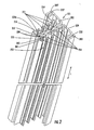
- FIG. 1A is a perspective view of a power interconnect assembly 100 and FIG. 1B is a partially exploded perspective view of the power interconnect assembly 100 of FIG. 1A .
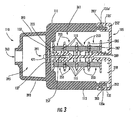
- FIG. 3 is a cross-sectional view of the power interconnect assembly 100 of FIG. 1A , taken generally along a line 3-3 as shown in FIG. 1A .
- a power interconnect assembly 100 includes a longitudinally extending base member 105 with one or more interconnect modules 110 coupled to the base member 105.
- the power interconnect assembly 100 includes a longitudinally extending interconnect module receiving portion 123 and a termination section 130 on an end thereof.
- the interconnect module receiving portion 123 is configured to receive a plurality of longitudinally spaced interconnect modules 110.
- the longitudinal direction refers to the direction indicated by the arrow L of FIG. 1A .
- spacer members 125 coupled to the base member 105 extend longitudinally between and abut ones of the interconnect modules 110.
- the interconnect modules 110 and spacer members 125 extend from a first end 105a of the base member 105 to a second end 105b of the base member 105 to define a cavity 361 ( FIG. 3 ). As best seen in FIGs.
- a plurality of longitudinally extending bus bars 115 of the power interconnect assembly 100 are enclosed by the cavity 361.
- the bus bars 115 may be coupled to high voltage and/or current sources, the enclosing cavity 361 may provide for protection from unintended incidental contact with such high voltage and/or current sources.
- the base member 105 includes a plurality of longitudinally extending bus bar receiving channels 251, in which a plurality of longitudinally extending bus bars 115 may be positioned, as seen in FIG. 3 .
- the channels 251 each include openings 253 exposing bus bars 115 positioned therein to allow coupling of the bus bars 115 to the interconnect members 110 proximate the interconnect members 110 at a plurality of longitudinal locations L 0 , L 0 ', L 0 ", L 0 "', L 0 "", L 0 ""' along the base member 105.
- the openings 253 are longitudinally extending openings extending throughout the interconnect module receiving portion 123 (see FIG. 1B ) that allow connection of electrical connection members of the interconnect modules 110 to the bus bars 115 at any location in the interconnect module receiving portion 123.
- the base member 105 further includes a longitudinally extending interconnect module receiving member 255.
- the interconnect module receiving member 255 includes a longitudinally extending mounting channel 257 on a face thereof.
- the interconnect modules 110 may be mounted to the base member 105 by screw members 471 received in and engaging the mounting channel 257.
- the mounting channel 257 in some embodiments extends through the interconnect module receiving portion 123 to allow the interconnect modules to be mounted at selectable longitudinal locations L 0 , L 0 ', L 0 ", L 0 "', L 0 "", L 0 ""' (see FIG. 1A ).
- the base member 105 includes a rack mounting wall portion 259 and a bus bar receiving portion 254, including the bus bar receiving channels 251, extending from the rack mounting wall portion 259.
- the rack mounting wall portion 259 includes interconnect module receiving channels 252, 252' on respective first and second ends thereof.
- the receiving channels 252, 252' are configured to receive ends 135, 135' of the interconnect modules 110 coupled to the base member 105 as seen in FIG. 3 .
- the bus bar receiving portion 254 has an end portion 254a, displaced from the rack mounting wall portion 259, that includes the mounting channels 257 therein and defines the interconnect module receiving member 255.
- the base member 105 is an extruded polymeric member.
- the base member 105 may be polystyrene and/or polyphenylene ether.
- the base member 105 is a longitudinally extending extruded member having uniform cross-sectional shape throughout both the interconnect module receiving portion 123 and through the termination section 130. The length of the base member 105 may be varied and selected to conform with the requirements and dimensions of a power assembly rack in which it will be utilized or the like.
- a power interconnect assembly 100 may be sized to extend across a rack, a plurality of racks, or the like, by variations in the length of the base member 105 utilized and a single termination section 130 or multiple termination sections 130 may be provided on a given base member 105.
- a variation in the number of bus bars 115 accommodated in the power interconnect assembly 100 may be provided by variations in the number of channels 251 provided in the base member 105 and/or the number of channels into which a bus bar 115 is inserted.
- each of the channels 251 in the embodiments of FIGs. 2 and 3 are defined by respective pairs of partition walls 285.
- a thickened retaining tab portion 287 is shown on each of the partition walls 285 that may be used to retain a bus bar 115 snapped into a respective channel 251 through a corresponding opening 253 in the channel 251 or slid through an end of the channel 251.
- spacers 289 positioned on a bottom wall of the respective channels 251 extending between the partition walls 285 thereof.
- the spacers 289 may serve to position the bus bars 115 displaced from the back wall. Such an arrangement may facilitate cooling of the bus bars 115 by allowing increased airflow to pass along a back face of the respective bus bars 115 in the channels 251.
- the first L-shaped member 113 extends from a first end 135 positioned in a first 252 of the receiving channels of the rack mounting wall portion 259 to a second end 137 adjacent the interconnect module receiving member 255 and extending over the mounting channel 257.
- the second L-shaped member 111 extends from a first end 135' positioned in the other 252' of the receiving channels of the rack mounting wall portion 259 to a second end 137' adjacent the interconnect module receiving member 255 and extending over the mounting channel 257 with the first L-shaped member 113 therebetween.
- the connector receiving opening 363 is positioned over the mounting channel 257 and is defined by the overlapping first 113 and second 111 L-shaped members and is configured to receive the connecting member 117.
- the first 113 and second 111 L-shaped members may be, for example, a polymer such as polystyrene and/or polyphenylene ether (e.g., Noryl ®).
- each of the interconnect module receiving channels 252, 252' includes a corresponding lock tab 283, 283' configured and positioned to cooperate with respective lock tabs 135a, 135a' located on the ends 135, 135' of the L-shaped members 111, 113 .
- each of the L-shaped members 111, 113 includes an extension portion 393 thereon which, once positioned as shown in FIG. 3 , define an opening 363 configured to receive the connector member 117.
- the extension portions 393 further define an enclosed volume 395 in which electrical connections, such as wiring and the like, may be arranged.
- FIG. 3 also illustrates an overlap portion 391 formed by the overlapping ends portions 137, 137' of the respective L-shape members 111, 113. Note that the cross-sectional illustration of FIG. 3 includes this overlap portion 391 and the opening 363. However, it will be understood that the cross-sectional view of FIG.
- the power interconnect assembly 100 in the illustrated embodiments includes a plurality of linking electrical connection members 119 coupling ones of a plurality of electrical connectors 121 of the connector member 117 to corresponding ones of the plurality of bus bars 115.
- the connection members 119 are shown as coupled to respective bus bars 115 by a connector member, such as a bolt 472 engaged in a threaded opening 473 formed in the bus bar at a location proximate the connector member 117.
- the linking electrical connection members 119 allow the electrical connectors 121 of the connector member 117 to be selectively coupled to designated ones of the plurality of bus bars 115 to define a connection arrangement between the connector member 117 and the bus bars 115.
- Different ones of the interconnect modules 110 and the respective connector members 117 may include a connection arrangement between the connector members 117 and the bus bars 115 that differs between the respective connector members 117. Nonetheless, the connector members 117 themselves may have a same form factor across different interconnect modules 110.
- the form factor is a fingerproof connector, such as fingerproof power pole pack connectors available from Anderson Power Products.
- respective ones of the interconnect modules 110 are coupled to the base member 105 at selectable longitudinal locations L 0 , L 0 ', L 0 ", L 0 "', L 0 "", L 0 ""'.
- the linking electrical connection members 119 couple the connector members 117 to the bus bars 115 at locations L 1 , L 2 , L 3 proximate the respective longitudinal locations L 0 , L 0 ', L 0 ", L 0 "', L 0 "", L 0 ""'.
- the connector 117 may have a keying arrangement in some embodiments of the present invention restricting what profile corresponding pluggable connectorized cable from a power component may be received in the keyed connector member 117.
- Different ones of the connector members 117 may have different keying arrangements so that a first of the connector members 117 may block insertion of a pluggable connectorized cable keyed to a second of the connector members 117 and the second connector member 117 may block insertion of a pluggable connectorized cable keyed to the first connector member 117.
- a self tapping screw member 471 may be used extending through the first 113 and second 111 L-shaped members and into the mounting channel 257 to couple the first 113 and second 111 L-shaped members to the base member 105.
- Such an arrangement may be utilized to allow flexible positioning of the connector member 117 and interconnect module 110 at any desired selectable longitudinal location along the interconnect module receiving portion 123 of the interconnect assembly 100.
- the interconnect modules 110 may be arranged in an abutting relationship at respective longitudinal locations along the base member 105.
- the interconnect modules 110 may abut each other or may abut a spacer member 125 positioned therebetween.
- respective mating portions 475, 477 may be provided on the interconnect modules 110 to allow for an interleaved an overlapping relation between adjacent interconnect modules 110 and/or spacer members 125 so as to define the cavity 361 enclosing the bus bars 115.
- a plurality of input connectors 131, 133 are included in the terminated section 130 that are coupled to respective ones of the bus bars 115.
- the input connectors 131 are shown arranged to provide connection of an input cable or the like to a respective associated single one of the bus bars 115, including providing a cable connection portion 502 coupled by respective different length bridging members 504 to the bus bar connector portion 506.
- variable length of the bridging members 504 may allow for positioning of each of the cable connection portions 502 along a common plane, while connecting the respective connectors 131 to different ones of the bus bars 115 in a one-to-one relationship.
- a bridging member 514 allows connection of multiple layer cable connection portions 512 to a same one of the bus bars 115 through a bus bar connecting portion 516 extending from the common bridging member 514.
- multiple input/output lines may be coupled to a single bus bar 115 using the connectors 133, while other ones of the bus bars 115, six of them as shown in FIG. 5 , may be connected to separate single input lines.
- an eighth of the bus bars 115 may be separately connected to using a wire bus bar connection member 628 having a cable 626 extending therefrom to an input connector 624.
- the bus bar 115 coupled to by the connector 628 may provide a neutral reference coupled through the input connector 624 in some arrangements.
- the termination section 130 may include a protected housing member 620 around the input connectors 131, 133, 624.
- a protective plate 622 may be coupled to the housing 620.
- the plate 622 may include openings 632 for receiving input wires coupled through the connectors 131 and an opening 630 receiving wires coupled through the input connectors 133.
- the plate 622 further is shown as including a cut-out for the input connector 624.
- an interconnect module 110 may include a plurality of connector members 117 therein.
- the connection arrangement between ones of the connector members 117 and the bus bars 115 may differ for respective ones of connector members 117 of an interconnect module 110 and the respective connector members 117 may have the same form factor as seen in FIG. 7A .
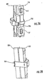
- Bracketing arrangement that may be used to couple a power interconnect assembly 100 to a rack of a power assembly or the like.
- a two part bracket 702 is shown in FIG. 7A and 7B extending around the power interconnect assembly 100.
- the respective halves of the bracket 702 are coupled at one end through interlocking portions 704 and another end by connector members 706 so as to be wrapped around a power interconnect assembly 100 and coupled thereto.
- the bracket 702 may be arranged to have a face thereof configured to mate with a corresponding receiving channel, bracket or the like positioned in a power supply rack.
- a plurality of brackets 702 may be used for coupling a power interconnect assembly 100 to a rack of a power assembly or the like. Once in the rack, respective ones of the power components may be coupled to the corresponding interconnect module 110 and connector members 117 having the desired connection arrangement to the bus bars 115 for the respective power components.
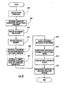
- a plurality of power components of the power supply are identified (block 800).
- a connection arrangement for each of the plurality of power components to the electrical bus connections are determined (block 805).
- a longitudinally extending base member including a plurality of bus bars therein corresponding to respective ones of the electrical bus connections, is provided (block 810).
- a plurality of connector members each of the connector members being configured to receive a pluggable connectorized cable from a power component, are provided (block 815).
- Each of the connector members provided at block 815 has a plurality of electrical connectors at defined positions therein.
- a longitudinal location associated with each of the plurality of power components is also determined.
- Ones of the electrical connectors are electrically connected to corresponding ones of the bus bars based on the determined connection arrangement of respective ones of the power components to be associated with the connector member (block 825).
- An interconnect module is coupled to the base member for each of the plurality of power components with the associated connector member positioned therein to provide a configured power interconnect assembly covering the bus bars (block 830).
- the respective interconnect modules and connector members may be positioned on the base member at determined longitudinal locations for the associated power component members in embodiments where the power components are determined to have associated longitudinal locations at block 820.
- operations further include mounting the configured power interconnect assembly to a rack of the power supply (block 835).
- the plurality of power components are positioned in the rack (block 840). Respective ones of the power components are coupled to their associated connector members in the power interconnect assembly using pluggable connectorized cables extending from their respective ones of the power components (block 845).
- UPS system may include a plurality of UPS system component modules, such as UPS modules, battery modules, power distribution modules, and the like. Each may be configured to be arranged in one or more equipment racks and may include at least one flexible power cable extending therefrom and a pluggable connector at an end thereof.
- the UPS system may further include a modular power interconnect assembly, e.g., an assembly configured along the lines of the assemblies described above.
- the power interconnect assembly may be attached to the one or more equipment racks in a number of different ways, as described in further detail below. Respective ones of the connectors of the UPS system component modules are pluggably mated with respective ones of connectors of the power interconnect assembly such that the power interconnect assembly provides electrical interconnection among the plurality of UPS system component modules.
- UPS system components may be integrated with load modules in equipment racks.
- UPS modules and/or other UPS system component modules such as battery modules, transformer modules, switch modules, and power distribution unit (PDU) modules, may be arranged in one or more equipment racks that also house loads, such as servers, routers, hubs and other data processing and/or data communications equipment.
- loads such as servers, routers, hubs and other data processing and/or data communications equipment.
- the UPS modules and/or other UPS system components may be configured to provide power to such loads.
- the UPS system component modules may be interconnected using one or more modular power interconnect assemblies along lines described herein to provide, among other things, input power paralleling, output power paralleling, battery power distribution and the like among the UPS system component modules.
- FIG. 9 illustrates a modular UPS system 900 according to some embodiments of the present invention, more particularly, an example of how a modular power interconnect assembly may be used to support paralleling of UPS system components.
- the system 900 includes an equipment rack 910, e.g., a standard 19-inch or similar rack.
- a plurality of UPS system component modules here shown as including a plurality of UPS modules 920, is arranged in a columnar fashion in the rack 910.
- the UPS modules 920 may include any of a number of different types of UPSs, for example, on-line, standby, line-interactive or other types of UPSs.
- Each UPS module 920 has a flexible power cable 922 extending therefrom and terminating with a connector 924.
- each UPS module 920 further includes at least one power outlet 926 that is configured to be connected to external loads.
- the system 900 further includes a modular power interconnect assembly 930 that is attached to the equipment rack 910.
- the power interconnect assembly 930 may have a configuration along the lines described above with reference to FIGs. 1-8 , i.e., may include an elongate housing with a plurality of substantially parallel bus bars running along a length thereof, with connectors 932 positioned at a face of the housing and spaced along the length of the housing.
- the power interconnect assembly 930 may be attached or otherwise mounted in and/or on the equipment rack using, for example, the mounting configuration described above.
- the power interconnect assembly 930 may be configured to support parallel interconnection of the UPS modules 920 when the connectors 924 of the power cables 922 of the UPS modules 920 are pluggably mated with the connectors 932 of the power interconnect assembly 930.
- power inputs 921 of the UPS modules may be parallel connected by common connection to a bus bar(s) in the power interconnect assembly 930.
- the power inputs 921 may be fed, for example, from an AC input cable 950 attached at or near a bottom end of the power interconnect assembly 230.
- power outputs 923 of the UPS modules 920 may be parallel connected by, for example, common connection to another bus bar(s) of the power interconnect assembly 930. As shown, the parallel connected power outputs 923 may also be electrically coupled to the power outlets 926 of the UPS modules 920 that serve external loads. It will be appreciated that, in this manner, the UPS modules 920 may operated in a parallel redundant manner such that, for example, a load coupled to a given one of the UPS modules 920 may be served by one or more of the other UPS modules 920 in event of failure of the given UPS module 920. It will be appreciated that, although FIG. 9 illustrates provision of power to external loads via outlets 926, other embodiments of the present invention may connect to loads in other ways.
- loads may be connected via the power interconnect assembly 930 (or another such assembly), e.g., a power cable may be connected to output power bus bars of the power interconnect assembly 930 and fed to a power distribution (PDU) module positioned in the same rack or in another rack that provides for connection of loads.
- a modular power interconnect assembly e.g., the assembly 930, may support connection between the UPS modules 920 and a power distribution rack that serves rackmounted loads as described in a copending United States Patent Application Publication US 2007/0217128 A1 (Serial. No. 11/378,054 ), entitled “Modular Electronic Systems and Methods using a Flexible Power Distribution Interface,” filed concurrently herewith.
- the power interconnect assembly 930 may support additional connections.
- the UPS modules 920 may have internal batteries, and the power interconnect assembly 930 may include bus bar connections to support provision of DC busses therein, such that the batteries of the UPS modules 930 may be parallel interconnected in a manner similar to the power input and output connections shown in FIG. 9 .
- the power interconnect assembly 930 (or an additional, similar power interconnect assembly mounted, for example, in parallel with the power interconnect assembly 930) may be configured to support an external battery connection, similar to the AC input 950 shown in FIG. 9 .
- Such an external battery connection may be used, for example, to connect to an external battery that serves the UPS modules 920. It will be appreciated that such an external DC connection may be used for UPS modules that do not have internal batteries, or to supplement battery power for UPS modules that do include internal batteries.
- a configuration along the lines described with reference to FIG. 9 may be used with other types of UPS system component modules.
- a battery rack may have a modular construction similar to that shown for the UPS modules 920 of FIG. 9 , wherein, instead of a column of UPS modules 920, a rack includes a columnar arrangement of battery modules that are interconnected by a power interconnect assembly having a form factor similar to the power interconnect assembly 930.
- UPS modules and battery modules may be arranged together in a single rack in a similar manner, and interconnected using a power interconnect assembly having a form factor similar to the power interconnect assembly 930.
- Such a rack may further include other types of modules, such as transformer or switch modules that may be similarly interconnected.
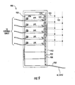
- FIG. 10 illustrates another exemplary UPS system 1000 according to further embodiments of the present invention wherein two UPS modules 1030, a transformer (xfmr) module 1040 and a power distribution unit (PDU) module 1020 are arranged in a columnar fashion in an equipment rack 1010.
- the modules 1020, 1030, 1040 have respective power cables 1022, 1032, 1042 extending therefrom and terminating in respective connectors 1024, 1034, 1044.
- An elongate power interconnect assembly 1050 is mounted vertically in the equipment rack 1010, extending along the column of modules 1020, 1030, 1040.
- the power interconnect assembly 1050 includes a plurality of connectors 1052 spaced along a face thereof.
- the power interconnect assembly 1050 provides parallel connection of power inputs 1031 of the UPS modules 1030 with a power output 1041 of the transformer module 1040, e.g., by common connection to a bus bar(s) the power interconnect assembly 1050.
- the power interconnect assembly 1050 also supports parallel interconnection of power outputs 1033 of the UPS modules 1030 with a power input 1021 of the power distribution module 1020.
- the transformer module 1040 may be fed from an AC input 1060 to the power interconnect assembly 1050.
- modules shown in FIG. 10 is an illustrative example, and that other embodiments of the present invention may include other collections and arrangements of UPS system component modules.
- a multi-module arrangement such as that shown in FIG. 10 could include modules, such as bypass switch and battery modules, in addition to the UPS, transformer and PDU modules shown. Interconnection among these modules may be provided using one or more pluggable power interconnect assemblies similar to the power interconnect assembly 1050 shown in FIG. 10 .
- a power interconnect assembly along the lines discussed above may also support a horizontal arrangement in a row of equipment racks.
- a system 1100 includes a plurality of UPS modules 1130 that are arranged in a horizontal row in a row of equipment racks 1110.
- An elongate power interconnect assembly 1140 is attached to the plurality of equipment racks 1110.
- the power interconnect assembly 1140 may be attached along bottom rear faces of the racks 1110 using, for example, clamps, mounting brackets or other mountings. It will be appreciated, however, that the power interconnect assembly 1140 may be mounted in other locations, for example, along top portions of the back faces of the racks 1110 and/or on top of the racks 1110.
- the power interconnect assembly 1140 may provide parallel interconnection of the UPS modules 1130. As shown, for example, power outputs 1133 of the UPS modules 1130 may be connected in parallel, e.g., using common connection to a bus bar(s), by the power interconnect assembly 1140 when connectors 1134 of power cables 1132 of the UPS modules 1130 are pluggably mated with connectors 1142 of the power interconnect assembly 1140. Power outlets 1136 of the UPS modules 1130 are electrically connected to the power inputs 1133 and are configured to serve loads 1120, which are also positioned in the equipment racks 1110 via cables 1122. For example, in IT applications, the loads 1120 may include server, router, hub or the computer or data processing and/or communications modules that are powered by the UPS modules 1130.
- Connections between the loads 1120 and the UPS modules 1130 may be direct, as shown in FIG. 11 , and/or may use power strips or other intermediate distribution devices mounted in and/or on the equipment racks 1110. Power inputs of the UPS modules 1130 may also be parallel connected using the power interconnect assembly 1140 (or a similar separate power interconnect assembly), which receives AC power from an AC input 1150.
- the power interconnect assembly 1140 (or an additional power interconnect assembly) may also support battery interconnection.
- loads 1220 arranged in equipment racks 1210 may include first and second power inputs A, B, which feed, for example, redundant DC power supplies of the loads 1220.
- a row of UPS modules 1230 may be arranged in the racks 1210 in a manner similar to that described above with reference to FIG. 11 .
- power outputs 1233 of the UPS modules 1230 may be paralleled via the interconnect assembly 1240.
- Power outlets 1236 of the UPS modules 1230 are electrically coupled to the power outputs 1233, and to the first power inputs A of the loads 1220 via power cables 1222, thus providing a first power source for the loads 1220.
- An alternative power source may be coupled to the second power inputs B of the loads 1220.
- Connections between the loads 1220 and the UPS modules 1230 may be direct and/or may use power strips or other intermediate distribution devices mounted in and/or on the equipment racks 1210.
- Power inputs of the UPS modules 1230 may also be parallel connected using the power interconnect assembly 1240 (or a similar separate power interconnect assembly), which receives AC power from an AC input 1250.
- the power interconnect assembly 1240 (or an additional power interconnect assembly) may also support battery interconnection.
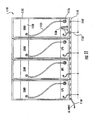
- FIG. 13 illustrates an exemplary arrangement for providing power to loads with redundant power inputs.
- first and second rows of UPS modules 1330a, 1330b are arranged in a row of equipment racks 1310, which also house loads 1320 that have redundant first and second power inputs A, B.
- Connectors 1334 of power output cables 1332 of respective ones of the rows of UPS modules 1330a, 1330b are pluggably mated with connectors 1342 of respective power interconnect assemblies 1340a, 1340b.
- the power interconnect assemblies 1340a, 1340b provide parallel output interconnections among the UPS modules 1330a, 1330b of the rows of UPS modules, e.g., along the lines described above with reference to FIG. 12 .
- First power input cables 1322a of the loads 1320 are connected to power outlets 1336 of the first row of UPS modules 1330a, while second power input cables 1332 of the loads 1320 are connected to power outlets 1336 of the second row of UPS modules 1330b.
- Connections between the loads 1320 and the UPS modules 1330a, 1330b may be direct and/or may use power strips or other intermediate distribution devices mounted in and/or on the equipment racks 1310.
- Power inputs of the UPS modules 1330a, 1330b may also be parallel connected using the power interconnect assemblies 1340a, 1340b (or a similar separate power interconnect assembly), which may receive one or more AC inputs 1350 (e.g., the assemblies 1340a, 1340b may be fed from the same power source or from separate power sources).
- the power interconnect assemblies 1340a, 1340b (or an additional power interconnect assembly) may also support battery interconnection.
- systems and methods are illustrative examples, and that other arrangements and/or combinations of components fall within the scope of the present invention.
- systems such as those illustrated in FIGs. 12 and 13 may further include additional other types of UPS system component modules, such as battery, switch, and transformer modules.
Landscapes
- Engineering & Computer Science (AREA)
- Power Engineering (AREA)
- Microelectronics & Electronic Packaging (AREA)
- Charge And Discharge Circuits For Batteries Or The Like (AREA)
- Connector Housings Or Holding Contact Members (AREA)
Claims (22)
- Système d'alimentation sans coupure (UPS) modulaire, comprenant .
une pluralité de modules des composants du système UPS (920), chacun étant disposé dans au moins un bâti d'équipement (910), chacun des modules des composants du système UPS ayant au moins un câble d'alimentation flexible (922) s'étendant de ceux-ci et ayant un premier connecteur enfichable (924) à une extrémité de celui-ci ; et
un ensemble d'interconnexion d'alimentation modulaire (930) fixé à l'au moins un bâti d'équipement, l'ensemble d'interconnexion de puissance modulaire comprenant un boîtier (105, 111, 113), une pluralité de barres omnibus (115) positionnées dans le boîtier, et une pluralité de deuxièmes connecteurs (932) positionnés à une face du boîtier, électriquement connectés à la pluralité de barres omnibus et configurée de manière à s'accoupler avec enfichage aux premiers connecteurs pour assurer une interconnexion électrique entre la pluralité de modules des composants du système UPS. - Système UPS de la revendication 1, dans lequel des connecteurs respectifs parmi les premiers connecteurs sont accouplés avec enfichage à des connecteurs respectifs parmi les deuxièmes connecteurs de sorte que l'ensemble d'interconnexion de puissance assure une interconnexion électrique entre la pluralité de modules des composants du système UPS.
- Système UPS de la revendication 2 :dans lequel les modules des composants du système UPS sont disposés dans une rangée ou colonne ;dans lequel le boîtier de l'ensemble d'interconnexion de puissance comprend un boîtier allongé ;dans lequel la pluralité de barres omnibus comprend des barres omnibus allongées disposées essentiellement en parallèle et s'étendant le long d'une longueur du boîtier allongédans lequel la pluralité de deuxièmes connecteurs sont espacés le long de la longueur du boîtier ; etdans lequel l'ensemble d'interconnexion de puissance s'étend le long de la rangée ou colonne des modules des composants du système UPS.
- Système UPS de la revendication 3, dans lequel les modules des composants du système UPS sont positionnés dans une colonne verticale dans un seul bâti d'équipement et dans lequel l'ensemble d'interconnexion de puissance est monté verticalement dans et/ou sur le seul bâti d'équipement.
- Système UPS de la revendication 3, dans lequel les modules des composants du système UPS sont positionnés dans une rangée horizontale des bâtis d'équipement et dans lequel l'ensemble d'interconnexion de puissance est monté horizontalement dans et/ou sur la rangée des bâtis d'équipement.
- Système UPS de la revendication 2 :dans lequel la pluralité de modules des composants du système UPS comprend une pluralité de modules UPS ; etdans lequel l'ensemble d'interconnexion de puissance assure l'entrée et/ou la sortie en parallèle des modules UPS.
- Système UPS de la revendication 2 :dans lequel la pluralité de modules des composants du système UPS comprend une pluralité de modules UPS ;dans lequel les câbles d'alimentation comprennent des câbles de sortie de puissance couplés à des sorties de puissance des modules UPS ;dans lequel l'ensemble d'interconnexion de puissance assure une sortie en parallèle des modules UPS ; etdans lequel les modules UPS comprennent en outre des prises de courant électriquement couplées aux sorties de puissance et configurées pour être électriquement couplées à des charges externes.
- Système électronique comprenant le système UPS de la revendication 7 et au moins une charge dans l'au moins un bâti d'équipement, dans lequel l'au moins une charge est configurée pour fonctionner de façon redondante à partir des alimentations de puissance au niveau de ses premières et deuxièmes entrées, et
dans lequel des prises de courant respectives de premier et deuxième modules respectifs parmi les modules UPS sont électriquement couplées à des entrées respectives parmi les premières et deuxièmes entrées de puissance de l'au moins une charge. - Système électronique de la revendication 8 :dans lequel l'au moins un bâti d'équipement comprend une pluralité de bâtis d'équipement ;dans lequel l'au moins une charge comprend une pluralité de charges, dont des charges respectives sont positionnées dans des bâtis respectifs de la pluralité de bâtis d'équipement ;dans lequel des modules respectifs parmi la pluralité de modules UPS sont positionnés dans des bâtis respectifs parmi la pluralité de bâtis d'équipement ;dans lequel l'ensemble d'interconnexion de puissance est configuré pour assurer une sortie en parallèle de la pluralité de modules UPS ; etdans lequel les prises des modules UPS sont électriquement couplées aux premières entrées de puissance des charges, et dans lequel les deuxièmes entrées de puissance des charges sont électriquement couplées à une source d'alimentation alternative.
- Système UPS de la revendication 2 :dans lequel la pluralité de modules des composants du système UPS comprend un module de distribution de puissance et un module UPS ;dans lequel les câbles d'alimentation comprennent un premier câble d'alimentation couplé à une sortie de puissance du module UPS et un deuxième câble d'alimentation couplé à une entrée de puissance du module de distribution de puissance ; etdans lequel l'ensemble d'interconnexion de puissance connecte électriquement la sortie de puissance du module UPS et l'entrée de puissance de l'unité de distribution de puissance.
- Système UPS de la revendication 10, dans lequel la pluralité de modules des composants du système UPS comprend en outre un module de transformateur, dans lequel les câbles d'alimentation comprennent en outre un troisième câble d'alimentation couplé au module de transformateur et un quatrième câble de puissance couplé au module UPS, et dans lequel l'ensemble d'interconnexion d'alimentation interconnecte électriquement le module de transformateur et le module UPS.
- Système UPS de la revendication 1, dans lequel les modules des composants du système UPS et/ou l'ensemble d'interconnexion d'alimentation sont/est configuré(s) pour être fixé(s) aux points de montage du bâti normalisé.
- Système UPS de la revendication 1, dans lequel la pluralité de modules des composants du système UPS comprend un module UPS, un module de batterie, un module de transformateur, un module de commutation, et/ou un module d'une unité de distribution de puissance (PDU).
- Procédé comprenant le fait :de disposer une pluralité de modules des composants du système UPS (920) dans au moins un bâti d'équipement (910), chacun des modules des composants du système UPS ayant au moins un câble d'alimentation flexible (922) s'étendant de ceux-ci et ayant un premier connecteur enfichable (924) à son extrémité ; etde monter un ensemble d'interconnexion d'alimentation modulaire (930) dans et/ou sur l'au moins un bâti d'équipement, l'ensemble d'interconnexion d'alimentation comprenant un boîtier (105, 111, 113), une pluralité de barres omnibus (115) positionnées dans le boîtier, et une pluralité de deuxièmes connecteurs (932) positionnés à une face du boîtier, électriquement connectés à la pluralité de barres omnibus et configurés pour s'accoupler avec enfichage aux premiers connecteurs.
- Procédé de la revendication 14 :dans lequel la disposition d'une pluralité de modules des composants du système UPS dans l'au moins un bâti d'équipement comprend la disposition des modules des composants du système UPS dans une rangée ou colonne ;dans lequel le boîtier de l'ensemble d'interconnexion d'alimentation comprend un boîtier allongé, dans lequel la pluralité de barres omnibus comprend des barres omnibus allongées disposées essentiellement en parallèle et s'étendant le long d'une longueur du boîtier allongé, et dans lequel la pluralité de deuxièmes connecteurs sont espacés le long de la longueur du boîtier ; etdans lequel le montage de l'ensemble d'interconnexion d'alimentation modulaire dans et/ou sur l'au moins un bâti d'équipement comprend le montage de l'ensemble d'interconnexion d'alimentation de sorte qu'il s'étende le long de la rangée ou colonne des modules des composants du système UPS.
- Procédé de la revendication 14, dans lequel la disposition des modules des composants du système UPS en une rangée ou colonne comprend la disposition des modules des composants du système UPS dans une colonne verticale dans un seul bâti d'équipement et dans lequel le montage de l'ensemble d'interconnexion d'alimentation de sorte qu'il s'étende le long de la rangée ou colonne des modules des composants du système UPS comprend le montage de l'ensemble d'interconnexion d'alimentation verticalement dans et/ou sur le seul bâti d'équipement.
- Procédé de la revendication 14, dans lequel la disposition d'une pluralité de modules des composants du système USP dans l'au moins un bâti d'équipement comprend la disposition des modules des composants du système UPS en une rangée horizontale de bâtis d'équipement et dans lequel le montage de l'ensemble d'interconnexion d'alimentation de sorte qu'il s'étende le long de la rangée ou colonne des modules des composants du système UPS comprend le montage de l'ensemble d'interconnexion d'alimentation horizontalement dans et/ou sur la rangée de bâtis d'équipement.
- Procédé de la revendication 14, comprenant en outre des connecteurs respectifs accouplés par enfichage parmi les premiers connecteurs à des connecteurs respectifs parmi les deuxièmes connecteurs de sorte que l'ensemble d'interconnexion d'alimentation assure une interconnexion électrique entre la pluralité de modules des composants du système UPS.
- Procédé de la revendication 18 :dans lequel la pluralité de modules des composants du système UPS comprend une pluralité de modules UPS ; etdans lequel des connecteurs respectifs accouplés par enfichage parmi les premiers connecteurs à des connecteurs respectifs parmi les deuxièmes connecteurs de sorte que l'ensemble d'interconnexion d'alimentation assure une interconnexion électrique entre la pluralité de modules des composants du système UPS comprend des connecteurs respectifs accouplés par enfichage parmi les premiers connecteurs à des connecteurs respectifs parmi les deuxièmes connecteurs de sorte que l'ensemble d'interconnexion d'alimentation assure l'entrée et/ou la sortie en parallèle des modules UPS.
- Procédé de la revendication 18 :dans lequel la pluralité de modules des composants du système UPS comprend une pluralité de modules UPS ;dans lequel les câbles d'alimentation comprennent des câbles de sortie de puissance couplés à des sorties de puissance des modules UPS ;dans lequel la pluralité de modules UPS comprennent en outre des prises de courant électriquement couplées aux sorties de puissance ;dans lequel des connecteurs respectifs accouplés par enfichage parmi les premiers connecteurs à des connecteurs respectifs parmi les deuxièmes connecteurs de sorte que l'ensemble d'interconnexion d'alimentation assure une interconnexion électrique entre la pluralité de modules des composants du système UPS comprend des connecteurs respectifs accouplés par enfichage parmi les premiers connecteurs à des connecteurs respectifs parmi les deuxièmes connecteurs de sorte que l'ensemble d'interconnexion d'alimentation assure une sortie en parallèle des modules UPS ; etdans lequel le procédé comprend en outre le couplage électrique de charges externes aux prises de courant des modules UPS.
- Procédé de la revendication 18 :dans lequel la pluralité de modules des composants du système UPS comprend un module de distribution de puissance et un module UPS et les câbles d'alimentation comprennent un premier câble d'alimentation couplé à une sortie de puissance du module UPS et un deuxième câble d'alimentation couplé à une entrée de puissance du module de distribution de puissance ; etdans lequel des connecteurs respectifs accouplés par enfichage parmi les premiers connecteurs à des connecteurs respectifs parmi les deuxièmes connecteurs de sorte que l'ensemble d'interconnexion de puissance assure une interconnexion électrique entre la pluralité de modules des composants du système UPS comprend des connecteurs respectifs accouplés par enfichage parmi les premiers connecteurs à des connecteurs respectifs parmi les deuxièmes connecteurs de sorte que l'ensemble d'interconnexion d'alimentation assure une interconnexion électrique entre la pluralité de modules des composants du système UPS pour interconnecter électriquement la sortie puissance du module UPS et l'entrée de puissance de l'unité de distribution de puissance.
- Procédé de la revendication 14, dans lequel la pluralité de modules des composants du système UPS comprend un module UPS, un module de batterie, un module de transformateur, un module de commutation, et/ou un module d'une unité de distribution de puissance (PDU).
Applications Claiming Priority (1)
| Application Number | Priority Date | Filing Date | Title |
|---|---|---|---|
| US11/378,140 US7760516B2 (en) | 2006-03-17 | 2006-03-17 | Modular UPS systems and methods using modular interconnect assemblies |
Publications (3)
| Publication Number | Publication Date |
|---|---|
| EP1835794A2 EP1835794A2 (fr) | 2007-09-19 |
| EP1835794A3 EP1835794A3 (fr) | 2010-06-02 |
| EP1835794B1 true EP1835794B1 (fr) | 2012-10-03 |
Family
ID=38229674
Family Applications (1)
| Application Number | Title | Priority Date | Filing Date |
|---|---|---|---|
| EP07005482A Expired - Fee Related EP1835794B1 (fr) | 2006-03-17 | 2007-03-16 | Systèmes UPS modulaires et procédés utilisant des ensembles interconnectés modulaires |
Country Status (3)
| Country | Link |
|---|---|
| US (1) | US7760516B2 (fr) |
| EP (1) | EP1835794B1 (fr) |
| CN (1) | CN101087059B (fr) |
Families Citing this family (57)
| Publication number | Priority date | Publication date | Assignee | Title |
|---|---|---|---|---|
| US20050265013A1 (en) * | 2004-06-01 | 2005-12-01 | Keith Scott M | Modular communications shelf system and methods for using the same |
| US8319483B2 (en) | 2007-08-06 | 2012-11-27 | Solaredge Technologies Ltd. | Digital average input current control in power converter |
| US8947194B2 (en) | 2009-05-26 | 2015-02-03 | Solaredge Technologies Ltd. | Theft detection and prevention in a power generation system |
| US9088178B2 (en) | 2006-12-06 | 2015-07-21 | Solaredge Technologies Ltd | Distributed power harvesting systems using DC power sources |
| US11569659B2 (en) | 2006-12-06 | 2023-01-31 | Solaredge Technologies Ltd. | Distributed power harvesting systems using DC power sources |
| US8013472B2 (en) | 2006-12-06 | 2011-09-06 | Solaredge, Ltd. | Method for distributed power harvesting using DC power sources |
| WO2009073868A1 (fr) | 2007-12-05 | 2009-06-11 | Solaredge, Ltd. | Mécanismes de sécurité, procédés d'éveil et d'arrêt dans des installations de puissance réparties |
| US8963369B2 (en) * | 2007-12-04 | 2015-02-24 | Solaredge Technologies Ltd. | Distributed power harvesting systems using DC power sources |
| US11728768B2 (en) | 2006-12-06 | 2023-08-15 | Solaredge Technologies Ltd. | Pairing of components in a direct current distributed power generation system |
| US11735910B2 (en) | 2006-12-06 | 2023-08-22 | Solaredge Technologies Ltd. | Distributed power system using direct current power sources |
| US8473250B2 (en) | 2006-12-06 | 2013-06-25 | Solaredge, Ltd. | Monitoring of distributed power harvesting systems using DC power sources |
| US11855231B2 (en) | 2006-12-06 | 2023-12-26 | Solaredge Technologies Ltd. | Distributed power harvesting systems using DC power sources |
| US11687112B2 (en) | 2006-12-06 | 2023-06-27 | Solaredge Technologies Ltd. | Distributed power harvesting systems using DC power sources |
| US8319471B2 (en) | 2006-12-06 | 2012-11-27 | Solaredge, Ltd. | Battery power delivery module |
| US11888387B2 (en) | 2006-12-06 | 2024-01-30 | Solaredge Technologies Ltd. | Safety mechanisms, wake up and shutdown methods in distributed power installations |
| US9000617B2 (en) | 2008-05-05 | 2015-04-07 | Solaredge Technologies, Ltd. | Direct current power combiner |
| WO2010097787A1 (fr) * | 2009-02-25 | 2010-09-02 | Gamatronic Electronic Industries Ltd. | Système ups modulaire |
| US8643504B2 (en) * | 2009-06-07 | 2014-02-04 | Gregory J. Marcinek | Power distribution unit |
| US8446039B2 (en) * | 2009-12-11 | 2013-05-21 | Schneider Electric It Corporation | Apparatus, system and method employing a UPS |
| CN101807775B (zh) * | 2010-02-08 | 2012-03-07 | 深圳市克莱沃电子有限公司 | 模块化电源控制分配系统 |
| US8782443B2 (en) | 2010-05-25 | 2014-07-15 | Microsoft Corporation | Resource-based adaptive server loading |
| US8384244B2 (en) | 2010-06-09 | 2013-02-26 | Microsoft Corporation | Rack-based uninterruptible power supply |
| US8487473B2 (en) | 2010-06-24 | 2013-07-16 | Microsoft Corporation | Hierarchical power smoothing |
| WO2012024182A1 (fr) * | 2010-08-14 | 2012-02-23 | Waste2Watts | Gestion d'énergie de secours modulaire |
| US8587929B2 (en) * | 2010-10-22 | 2013-11-19 | Eaton Corporation | High density uninterruptible power supplies and related systems and power distribution units |
| US8952566B2 (en) | 2010-10-26 | 2015-02-10 | Microsoft Technology Licensing, Llc | Chassis slots accepting battery modules and other module types |
| US10673229B2 (en) | 2010-11-09 | 2020-06-02 | Solaredge Technologies Ltd. | Arc detection and prevention in a power generation system |
| US9072191B2 (en) * | 2010-12-30 | 2015-06-30 | Schneider Electric It Corporation | Configurable rack and related methods |
| FR2972576B1 (fr) * | 2011-03-11 | 2014-04-11 | Schneider Electric Ind Sas | Procede de realisation d'une installation de conversion d'energie electrique et installation obtenue par un tel procede |
| US8488302B2 (en) * | 2011-04-14 | 2013-07-16 | Eaton Corporation | Circuit breaker panel |
| GB2498365A (en) | 2012-01-11 | 2013-07-17 | Solaredge Technologies Ltd | Photovoltaic module |
| GB2498790A (en) | 2012-01-30 | 2013-07-31 | Solaredge Technologies Ltd | Maximising power in a photovoltaic distributed power system |
| GB2498791A (en) | 2012-01-30 | 2013-07-31 | Solaredge Technologies Ltd | Photovoltaic panel circuitry |
| WO2013162500A1 (fr) * | 2012-04-23 | 2013-10-31 | Hewlett-Packard Development Company, L.P. | Modération d'une charge |
| WO2013183011A2 (fr) * | 2012-06-07 | 2013-12-12 | Intal Tech Ltd. | Blocs de construction d'équipement électronique pour un montage sur bâti |
| US9310577B2 (en) | 2012-07-11 | 2016-04-12 | Adc Telecommunications, Inc. | Telecommunications cabinet modularization |
| TWI468886B (zh) * | 2013-03-28 | 2015-01-11 | Acbel Polytech Inc | Redundant power supply system |
| CN104218402B (zh) | 2013-05-30 | 2018-09-21 | 伊顿制造(格拉斯哥)有限合伙莫尔日分支机构 | 一种用于电源分配单元的定位装置 |
| US9431851B2 (en) | 2013-08-16 | 2016-08-30 | Eaton Corporation | UPS systems and methods using current-controlling low-loss modes |
| US9846467B2 (en) * | 2014-02-14 | 2017-12-19 | Amazon Technologies, Inc. | Power routing assembly for data center |
| WO2015128253A1 (fr) * | 2014-02-25 | 2015-09-03 | Abb Technology Ag | Modèle d'alimentation sans coupure horizontal |
| US20150357798A1 (en) * | 2014-06-05 | 2015-12-10 | Eaton Corporation | Integrated bus duct and ups systems |
| US9885845B2 (en) * | 2015-01-15 | 2018-02-06 | Commscope, Inc. Of North Carolina | Module and assembly for fiber optic interconnections |
| CN104883314A (zh) * | 2015-06-05 | 2015-09-02 | 苏州新奇迅网络有限公司 | 一种不断电式计算机网络路由器 |
| US10476298B1 (en) | 2015-09-02 | 2019-11-12 | Amazon Technologies, Inc. | Elevated automatic transfer switch cabinet |
| EP3166201B1 (fr) * | 2015-11-04 | 2019-01-02 | ABB Schweiz AG | Système d'alimentation sans interruption facile à entretenir |
| GB2547946B (en) * | 2016-03-04 | 2020-05-20 | Ge Aviat Systems Ltd | Method and apparatus for modular power distribution |
| WO2017174327A1 (fr) * | 2016-04-04 | 2017-10-12 | Eaton Industries (France) Sas | Baie pour équipement électronique |
| US11177663B2 (en) | 2016-04-05 | 2021-11-16 | Solaredge Technologies Ltd. | Chain of power devices |
| EP3467994A1 (fr) | 2017-10-03 | 2019-04-10 | CE+T Power Luxembourg SA | Virtualisation d'énergie pour centres de données, environnements de télécommunications et infrastructures équivalentes |
| US10455722B1 (en) * | 2017-05-30 | 2019-10-22 | Amazon Technologies, Inc. | Externally-mounted power supply containment unit |
| EP3454020A1 (fr) * | 2017-09-07 | 2019-03-13 | Endress+Hauser Wetzer GmbH+CO. KG | Appareil d'étanchéité modulaire ayant une unité de détection de défaillance |
| US11171510B2 (en) * | 2017-12-19 | 2021-11-09 | Zeon Corporation | Power wiring device |
| CN209448232U (zh) * | 2018-12-21 | 2019-09-27 | 华为数字技术(苏州)有限公司 | 一种配电设备及配电系统 |
| US11083104B2 (en) * | 2019-12-16 | 2021-08-03 | Microsoft Technology Licensing, Llc | Variable reliability and capacity data center design |
| US11287868B1 (en) * | 2020-07-15 | 2022-03-29 | Amazon Technologies, Inc. | Facility power backstopping system for power monitoring and power loss prevention |
| CN114765425B (zh) * | 2022-05-17 | 2023-01-17 | 上海百竹成航新能源有限责任公司 | 一种整流模块并联组件及其整流柜与直流供电系统 |
Family Cites Families (11)
| Publication number | Priority date | Publication date | Assignee | Title |
|---|---|---|---|---|
| EP0574628A1 (fr) * | 1992-06-19 | 1993-12-22 | Lumen Electronics Corporation | Alimentation sans coupure modulaire |
| US5982652A (en) * | 1998-07-14 | 1999-11-09 | American Power Conversion | Method and apparatus for providing uninterruptible power using a power controller and a redundant power controller |
| US6301095B1 (en) * | 1999-12-23 | 2001-10-09 | 3Com Corporation | System and method of distributing power to a plurality of electronic modules housed within an electronics cabinet |
| US6967283B2 (en) | 2001-03-20 | 2005-11-22 | American Power Conversion Corporation | Adjustable scalable rack power system and method |
| CN2490749Y (zh) * | 2001-06-08 | 2002-05-08 | 广州市南华西发电成套设备有限公司 | 备用供电电源装置 |
| JP3721106B2 (ja) * | 2001-09-03 | 2005-11-30 | 日本電気株式会社 | 通信機器の電源供給構造 |
| DE10359489B4 (de) * | 2003-02-27 | 2009-06-04 | Rittal Gmbh & Co. Kg | Elektrifiziereinrichtung für ein Rahmengestell eines Schaltschrankes oder Racks |
| US7236896B2 (en) * | 2003-09-30 | 2007-06-26 | Hewlett-Packard Development Company, L.P. | Load management in a power system |
| US7187265B1 (en) * | 2004-01-22 | 2007-03-06 | Sprint Communications Company L.P. | Equipment housing with interfacing computer |
| US7196900B2 (en) * | 2004-05-21 | 2007-03-27 | Server Technology, Inc. | Adaptable rack mountable power distribution apparatus |
| US7619868B2 (en) * | 2006-06-16 | 2009-11-17 | American Power Conversion Corporation | Apparatus and method for scalable power distribution |
-
2006
- 2006-03-17 US US11/378,140 patent/US7760516B2/en active Active
-
2007
- 2007-03-16 CN CN200710126677XA patent/CN101087059B/zh not_active Expired - Fee Related
- 2007-03-16 EP EP07005482A patent/EP1835794B1/fr not_active Expired - Fee Related
Also Published As
| Publication number | Publication date |
|---|---|
| EP1835794A2 (fr) | 2007-09-19 |
| CN101087059B (zh) | 2012-07-18 |
| US7760516B2 (en) | 2010-07-20 |
| US20070217178A1 (en) | 2007-09-20 |
| CN101087059A (zh) | 2007-12-12 |
| EP1835794A3 (fr) | 2010-06-02 |
Similar Documents
| Publication | Publication Date | Title |
|---|---|---|
| EP1835794B1 (fr) | Systèmes UPS modulaires et procédés utilisant des ensembles interconnectés modulaires | |
| US7252524B1 (en) | Power interconnect assemblies and methods for configuring the same | |
| US7542268B2 (en) | Modular electronic systems and methods using flexible power distribution unit interface | |
| EP2127510B1 (fr) | Procédés et systèmes de distribution de l'alimentation sans coupure comprenant des unités de distribution d'alimentation répartie | |
| US10951013B2 (en) | Multiple input power distribution shelf and bus bar assembly thereof | |
| US8107225B2 (en) | Adjustable scalable rack power system and method | |
| EP2659754B1 (fr) | Baie configurable et procédés associés | |
| US20120224313A1 (en) | Cabinet server system | |
| AU2011352969A1 (en) | Configurable rack and related methods | |
| US20170373528A1 (en) | Modular Uninterruptible Power Supply and Power Distribution System | |
| WO2010097787A1 (fr) | Système ups modulaire | |
| EP3461246A2 (fr) | Étagère de distribution d'énergie d'entrées multiples et son ensemble de barre de bus |
Legal Events
| Date | Code | Title | Description |
|---|---|---|---|
| PUAI | Public reference made under article 153(3) epc to a published international application that has entered the european phase |
Free format text: ORIGINAL CODE: 0009012 |
|
| AK | Designated contracting states |
Kind code of ref document: A2 Designated state(s): AT BE BG CH CY CZ DE DK EE ES FI FR GB GR HU IE IS IT LI LT LU LV MC MT NL PL PT RO SE SI SK TR |
|
| AX | Request for extension of the european patent |
Extension state: AL BA HR MK YU |
|
| PUAL | Search report despatched |
Free format text: ORIGINAL CODE: 0009013 |
|
| AK | Designated contracting states |
Kind code of ref document: A3 Designated state(s): AT BE BG CH CY CZ DE DK EE ES FI FR GB GR HU IE IS IT LI LT LU LV MC MT NL PL PT RO SE SI SK TR |
|
| AX | Request for extension of the european patent |
Extension state: AL BA HR MK RS |
|
| 17P | Request for examination filed |
Effective date: 20101202 |
|
| AKX | Designation fees paid |
Designated state(s): DE FR GB |
|
| 17Q | First examination report despatched |
Effective date: 20110330 |
|
| GRAP | Despatch of communication of intention to grant a patent |
Free format text: ORIGINAL CODE: EPIDOSNIGR1 |
|
| GRAS | Grant fee paid |
Free format text: ORIGINAL CODE: EPIDOSNIGR3 |
|
| GRAA | (expected) grant |
Free format text: ORIGINAL CODE: 0009210 |
|
| AK | Designated contracting states |
Kind code of ref document: B1 Designated state(s): DE FR GB |
|
| REG | Reference to a national code |
Ref country code: GB Ref legal event code: FG4D |
|
| REG | Reference to a national code |
Ref country code: DE Ref legal event code: R096 Ref document number: 602007025802 Country of ref document: DE Effective date: 20121129 |
|
| PLBE | No opposition filed within time limit |
Free format text: ORIGINAL CODE: 0009261 |
|
| STAA | Information on the status of an ep patent application or granted ep patent |
Free format text: STATUS: NO OPPOSITION FILED WITHIN TIME LIMIT |
|
| 26N | No opposition filed |
Effective date: 20130704 |
|
| REG | Reference to a national code |
Ref country code: DE Ref legal event code: R097 Ref document number: 602007025802 Country of ref document: DE Effective date: 20130704 |
|
| REG | Reference to a national code |
Ref country code: FR Ref legal event code: PLFP Year of fee payment: 10 |
|
| REG | Reference to a national code |
Ref country code: FR Ref legal event code: PLFP Year of fee payment: 11 |
|
| REG | Reference to a national code |
Ref country code: FR Ref legal event code: PLFP Year of fee payment: 12 |
|
| PGFP | Annual fee paid to national office [announced via postgrant information from national office to epo] |
Ref country code: GB Payment date: 20180226 Year of fee payment: 12 Ref country code: DE Payment date: 20180219 Year of fee payment: 12 |
|
| PGFP | Annual fee paid to national office [announced via postgrant information from national office to epo] |
Ref country code: FR Payment date: 20180220 Year of fee payment: 12 |
|
| REG | Reference to a national code |
Ref country code: GB Ref legal event code: 732E Free format text: REGISTERED BETWEEN 20181115 AND 20181130 |
|
| REG | Reference to a national code |
Ref country code: GB Ref legal event code: 732E Free format text: REGISTERED BETWEEN 20181206 AND 20181212 |
|
| REG | Reference to a national code |
Ref country code: DE Ref legal event code: R081 Ref document number: 602007025802 Country of ref document: DE Owner name: EATON INTELLIGENT POWER LIMITED, IE Free format text: FORMER OWNER: EATON POWER QUALITY CORP., CLEVELAND, OHIO, US Ref country code: DE Ref legal event code: R082 Ref document number: 602007025802 Country of ref document: DE Representative=s name: WAGNER & GEYER PARTNERSCHAFT MBB PATENT- UND R, DE Ref country code: DE Ref legal event code: R082 Ref document number: 602007025802 Country of ref document: DE |
|
| REG | Reference to a national code |
Ref country code: DE Ref legal event code: R119 Ref document number: 602007025802 Country of ref document: DE |
|
| GBPC | Gb: european patent ceased through non-payment of renewal fee |
Effective date: 20190316 |
|
| PG25 | Lapsed in a contracting state [announced via postgrant information from national office to epo] |
Ref country code: GB Free format text: LAPSE BECAUSE OF NON-PAYMENT OF DUE FEES Effective date: 20190316 Ref country code: DE Free format text: LAPSE BECAUSE OF NON-PAYMENT OF DUE FEES Effective date: 20191001 |
|
| PG25 | Lapsed in a contracting state [announced via postgrant information from national office to epo] |
Ref country code: FR Free format text: LAPSE BECAUSE OF NON-PAYMENT OF DUE FEES Effective date: 20190331 |