EP1835366A1 - Automobil-regler und softwareerstellungsverfahren und -system dafür - Google Patents
Automobil-regler und softwareerstellungsverfahren und -system dafür Download PDFInfo
- Publication number
- EP1835366A1 EP1835366A1 EP04822576A EP04822576A EP1835366A1 EP 1835366 A1 EP1835366 A1 EP 1835366A1 EP 04822576 A EP04822576 A EP 04822576A EP 04822576 A EP04822576 A EP 04822576A EP 1835366 A1 EP1835366 A1 EP 1835366A1
- Authority
- EP
- European Patent Office
- Prior art keywords
- description part
- hierarchical configuration
- processing
- generating
- software
- Prior art date
- Legal status (The legal status is an assumption and is not a legal conclusion. Google has not performed a legal analysis and makes no representation as to the accuracy of the status listed.)
- Withdrawn
Links
Images



Classifications
-
- G—PHYSICS
- G05—CONTROLLING; REGULATING
- G05B—CONTROL OR REGULATING SYSTEMS IN GENERAL; FUNCTIONAL ELEMENTS OF SUCH SYSTEMS; MONITORING OR TESTING ARRANGEMENTS FOR SUCH SYSTEMS OR ELEMENTS
- G05B19/00—Program-control systems
- G05B19/02—Program-control systems electric
- G05B19/04—Program control other than numerical control, i.e. in sequence controllers or logic controllers
- G05B19/042—Program control other than numerical control, i.e. in sequence controllers or logic controllers using digital processors
- G05B19/0426—Programming the control sequence
-
- F—MECHANICAL ENGINEERING; LIGHTING; HEATING; WEAPONS; BLASTING
- F02—COMBUSTION ENGINES; HOT-GAS OR COMBUSTION-PRODUCT ENGINE PLANTS
- F02D—CONTROLLING COMBUSTION ENGINES
- F02D41/00—Electrical control of supply of combustible mixture or its constituents
- F02D41/24—Electrical control of supply of combustible mixture or its constituents characterised by the use of digital means
- F02D41/26—Electrical control of supply of combustible mixture or its constituents characterised by the use of digital means using computer, e.g. microprocessor
-
- G—PHYSICS
- G06—COMPUTING OR CALCULATING; COUNTING
- G06F—ELECTRIC DIGITAL DATA PROCESSING
- G06F8/00—Arrangements for software engineering
- G06F8/20—Software design
-
- G—PHYSICS
- G05—CONTROLLING; REGULATING
- G05B—CONTROL OR REGULATING SYSTEMS IN GENERAL; FUNCTIONAL ELEMENTS OF SUCH SYSTEMS; MONITORING OR TESTING ARRANGEMENTS FOR SUCH SYSTEMS OR ELEMENTS
- G05B2219/00—Program-control systems
- G05B2219/20—Pc systems
- G05B2219/25—Pc structure of the system
- G05B2219/25389—Macro's, subroutines
Definitions
- the present invention relates to an automobile controller, as well as a method of and a system for generating software for a microprocessor constituting part of the automobile controller.
- Microprocessors including a CPU, a ROM, a RAM, an input/output signal processor, and other components have been used as controllers intended for automobile engine control and the like.
- Software installed in this type of microprocessor comprises application programs that perform control processing and device drivers that perform input and output operations so that a desired control operation is achieved.
- the device drivers for input and output operations are easily affected and a large number of person-hours involved in the modification become problematic.
- Modifications of hardware are broadly classified into two types; modifications of sensors and actuators that are subject to control and modifications of the microprocessor that performs control.
- a sensor, an actuator, or other hardware subject to control When a sensor, an actuator, or other hardware subject to control is modified, software is developed so that a target control operation is achieved, with reference to a hardware manual or another document in which its characteristics and specifications are described.
- the microprocessor When the microprocessor is modified, many person-hours are needed to extract portions to be modified, determine new specifications, perform a modification, and verify the modification with reference to a manual in which the specifications of the microprocessor are described.
- UNIX (a registered trademark), which is a general-purpose operating system (OS) intended for information systems, is available, as disclosed in Non-patent Document 1.
- OS operating system
- interfaces to the hardware subject to control are classified into three standard interfaces, which are block-type interfaces, message channel-type interfaces, and character-type interfaces. All input/output programs each use any one of the three types of virtual interfaces. Accordingly, software is structured with three layers, which are applications, virtual drivers, and actual driver programs, enabling application programs to be developed without having to worry about the modification of the hardware.
- Patent Document 1 a device driver is divided into three layers so that a modification of a program responsive to a modification of a device can be localized.
- Non-patent Document 2 a device driver is created as a high-order driver and a low-order driver; the high-order driver uses an interface for the low-order driver to perform processing, eliminating effects by modifications of the microprocessor and other hardware.
- Non-patent Document 1 S. J. Leffler, et al., translated by Akira Nakamura, et al., The Design and Implementation of the 4.3 BSD UNIX Operating System, Maruzen Co., Ltd. (1991 )
- An object of the present invention is to reduce person-hours taken for software modification involved in modification of hardware or a control method so as to increase application execution speeds and reduce necessary storage unit capacities.
- the present invention in one aspect, generates a first processing description part divided into a plurality of layers, an identifier expanding part for expanding an identifier used in the first processing description part, and a hierarchical configuration description part in which to describe the hierarchical configuration of the first processing description part, and also generates a second processing description part comprising a single layer, which results from an expansion of the hierarchical configuration of the first processing description part into a single layer in accordance with data described in the hierarchical configuration description part and the identifier expanding part.
- desired executable software can be obtained in a second processing description part, which is expanded into a single layer by using a first processing description part, a hierarchical configuration description part, an identifier expanding part, a preprocessor, and a compiler; in the first processing description part, processing for each layer is described by using macros representing labels defined for the each layer; in the hierarchical configuration description part, connection relationships among layers are defined by using macros representing the labels for each layer; the identifier expanding part performing macro expansion according to the hierarchical configuration description part.
- a software generating system in another aspect of the present invention comprises a means for generating a first processing description part divided into a plurality of layers, a means for generating an identifier expanding part for expanding an identifier used in the first processing description part, a means for generating a hierarchical configuration description part in which to describe the hierarchical configuration of the first processing description part, and a means for generating a second processing description part comprising a single layer, which results from an expansion of the hierarchical configuration of the first processing description part in accordance with data described in the hierarchical configuration description part and the identifier expanding part.
- a preprocessor for generating the second processing description part
- a compiler for translating the second processing description part into an object file
- a linker for generating control software to be written in a storage unit of the automobile controller by linking the object file to an application object file.
- software designed as a plurality of hierarchical layers is compiled into software that includes only a single layer and thereby does not suffer an overhead between layers.
- sensor actuator 71 ... device driver program source code, 72 ... build, 73 ... device driver object file, 902 ... device driver repository, 905 ... input/output terminal list, 906 ... hierarchical configuration generator, 911 ... preprocessor, 913 ... expanded processing description part, 914 ... compiler, 916 ... device driver object file, 917 ... application source code, 918 ... application object file, 919 ... linker, 921 ... control software
- FIG. 1 shows the structures of a device driver developed according to an embodiment of the present invention as well as applications and hardware.
- the drawing shows an example of a device driver 120 that accepts inputs obtained from sensors through input/output ports 131 to 133 of a microprocessor 130 and uses the inputs to calculate an amount of intake air and an intake air temperature.
- FIG. 2 shows the structure of an automobile engine control system in an embodiment of the present invention.
- the control unit 200 includes a CPU 201, an interrupt controller 202, a time pulse controller 203, an AD converter 204, a ROM 205, and a RAM 206. These components are interconnected through a bus 207 and make external accesses through an input/output port 208.
- the components 202 to 208 may be included in one device, or included in different devices and interconnected.
- Reference numeral 210 indicates a power supply for the control unit 200.
- a sensor actuator 220 to be controlled is connected to the control unit 200 through the input/output port 208.
- the sensor actuator 220 comprises an air flow sensor 221, an electronically controlled throttle 222, an injector 223, an ignition plug 224, an air-to-fuel ratio sensor 225 such as a lean air fuel (LAF) sensor, and a crank angle sensor 226.
- the control unit 200 controls these components. Specifically, to achieve control, the CPU 201 and other components in the control unit 200 write to and read from registers in the input/output port 208.
- Software in which a control method is described is stored in the ROM 205 and RAM 206 in the control unit 200.
- This embodiment relates to a method of generating this type of software in such a way that the software can be modified easily even when, for example, hardware is modified and that applications are executed fast and thus the capacity of memory can be reduced.
- the configuration of software executed by the control unit 200 in FIG. 2 will be described with reference again to FIG. 1.
- Software is broadly classified into three categories, which are an application program 100, operating system (OS) 110, and device driver 120.
- the application program 100 sends and receives information and processing to and from the OS 110 and device driver 120 through the application program interface (API) 140.
- API application program interface
- the OS 110 and device driver 120 control the application program through a hardware interface (HWI) 150 of the input/output ports 131 to 133 etc. of the microprocessor 130.
- HWI hardware interface
- the exemplary device driver 120 shown in the drawing performs an intake air amount calculation 121 and an intake air temperature calculation 122 according to inputs obtained from the sensors through the input/output ports 131 to 133 of the microprocessor 130.
- the device driver 120 accepts requests from an injection control application 101, an ignition control application 102, and the like in the application program 100 through the API 140.
- the CPU 130 is responsible for control of this; it performs target control by reading from and writing to the analog input/output ports 131 to 133 and the like through the HWI 150.
- the device driver 120 is developed in layers by breaking down it into, for example, the upper layer (L1) 160 and lower layer (L2) 170 so that points to modify are localized. There is no restriction on the number of layers; the device driver 120 can be implemented by an appropriate number of layers according to what is responsible for control and how large the software is. The description below assumes a case in which two layers are used.
- the upper layer (L1) 160 in the processing description part 180 includes the intake air amount calculation 121, intake air temperature calculation 122, and other modules that require input values needed by the application program 100.
- the lower layer (L2) 170 including modules that receive input values and perform general input processing, processing to be performed is described.
- a first-order filter analog input (FAI) 171 and Vcc correction analogy input (VAI) 172 are indicated.
- a concrete configuration between layers that indicates which upper layer uses which lower layer is described in the hierarchical configuration description part 191.
- the identifier expanding part 192 is used to associate the hierarchical configuration defined in the hierarchical configuration description part 191 with the processing description part 180 to obtain desired output.
- FIGs. 3A to 3D and FIGs. 4A to 4D illustrate concrete examples of the upper layer (L1) 160 and lower layer (L2) 170 in the processing description part 180, respectively, in detail. These examples will be described below.
- FIGs. 3A to 3D illustrate the intake air amount calculation (IAA) 121 in the upper layer (L1) 160 shown in FIG. 1 in detail.
- FIG. 3A outlines processing.
- the intake air amount calculation module has intake air amount update processing named processing name 1, intake air amount acquisition processing named processing name 2, and Vcc correction analog input provided as input processing necessary for this calculation.
- FIG. 3B is a flowchart that schematically shows the above intake air amount update processing.
- FIG. 3C is also a flowchart that schematically shows the above intake air amount acquisition processing.
- FIG. 3D is an example of program code that implements FIGs. 3A, 3B, and 3C.
- the Vcc correction analog input (VAI) in the lower layer L2 updates an input value in step 301, and the updated value is then obtained in step 302.
- a map for correcting air flow sensor characteristics is used to perform correction according to the obtained value in step 303.
- a value obtained by the above correction is stored in a buffer in step 304.
- the value in the above buffer is returned in step 305.
- FIG. 3D shows an example of a program source in which the above processing is described with macros in C.
- a call of another module is coded as Ln_Proc(_Ln(ID)), and data reference is coded as Ls_(ID).
- Ln is the layer name of a module to be called
- Proc is the name of processing to be called
- ID is the name of the calling module
- Ls is the layer name of the calling module.
- FIG. 4A to 4D illustrate the Vcc correction analog input (VAI) 172, which is an element of the lower layer (L2) 170 shown in FIG. 1, in detail.
- VAI Vcc correction analog input
- FIG. 4A outlines processing.
- the Vcc correction analog input module has Vcc correction analog input value update processing named processing name 1, Vcc correction analog input value acquisition processing named processing name 2, and input from a microprocessor port provided as an input type necessary for this processing.
- FIG. 4B is a flowchart for the Vcc correction analog input value update processing.
- FIG. 4C is also a flowchart for the Vcc correction analog input value acquisition processing.
- FIG. 4D is an example of source code that implements FIGs. 4A, 4B, and 4C.
- Vcc is input from a microprocessor port through the hardware interface (HWI) 150 in step 401.
- a Vcc correction coefficient is then multiplied to obtain an updated value in step 402.
- the updated value obtained is stored in a buffer in step 403.
- the value in the above buffer is returned in step 404.
- FIG. 4D shows an example of a program source in which the above processing is described with macros in C. Macros are described in the same way as in FIG. 3D.
- FIGs. 5A and 5B show the hierarchical configuration description part 191 in the device driver 120 shown in FIG. 1 in detail.
- FIG. 5A outlines the configuration, indicating that the label names of processing modules are IAT, IAA, VAI, and FAI, and that the label names of processing modules below these processing modules are FAI, VAI, AN1, and AN2. That is, the low-order module of the intake air temperature calculation (IAT) 122 is the first-order filter analog input 171, the label of which is FAI; the low-order module of the intake air amount calculation (IAA) 121 is the Vcc correction analog input 172, the label of which is VAI; the hardware corresponding to the first-order filter analog input 171 with the label FAI is the analog input/output port, the label of which is AN2; the hardware corresponding to the Vcc correction analog input 172 with the label VAI is the analog input/output port, the label of which is AN1.
- the low-order module of the intake air temperature calculation (IAT) 122 is the first-order filter analog input 171, the label of which is FAI
- FIG. 5B shows source code of the hierarchical configuration description part 191 implemented according to the hierarchical configuration in FIG. 5A.
- the source code is described with macros in the form of "#define ID_Ln IDn" or "#define ID _ADDR xxxx".
- ID is the identifier (label) of the device driver module;
- IDn is the identifier (label) of another module related to the module;
- _ADDR is an identifier indicating a microprocessor port;
- xxx is a port name.
- FIG. 6 shows the identifier expanding part 192 in the device driver 120 shown in FIG. 1 in detail.
- the identifier expanding part is in the form of "#define _Ln (ly) ly # #_Ln" "#define _ADDR (ly) ly# #_ADDR", or "#define Ln_(ly) Ln_# #ly".
- Ln is the name of the upper layer;
- ADDR is an arbitrary identifier indicating a port of the microprocessor; other symbols have the same meanings as described above.
- these identifiers are replaced with the labels of other layers by using the identifier linking function "# #" in C.
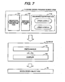
- FIG. 7 shows a development procedure in which the processing description part, hierarchical configuration description part, and identifier expanding part described above are used.
- the hierarchical configuration description part 711, identifier expanding part 712, and processing description part 713 in the device driver program source code 71 generated as described above are passed through the build 72 to obtain a device driver object file 73.
- the device driver object file 73 is output.
- the processing description part generated as layers is expanded into a single layer by the preprocessor 721, eliminating the overhead between the layers.
- FIGs. 8A to 8D illustrate examples of source code from which the overhead between layers is eliminated according to an embodiment of the present invention.
- FIG. 8A shows calling source code
- FIG. 8B shows code resulting from the expansion of the source code by the preprocessor 721.
- the preprocessor 721 performs macro expansion
- the inter-layer calling processing in steps 301 and 302 in FIG. 3B and step 401 in FIG. 4B is expanded into a single layer. Accordingly, processing to save arguments and stack pointers used to call other layers becomes unnecessary, speeding up the processing and downsizing the code.
- FIG. 8C shows machine code in the conventional technique
- FIG. 8D shows an example in which there is a reduction according to an embodiment of the present invention.
- the machine code for making a call in step 301 in FIG. 3B is a part 81 enclosed by dashed lines in FIG. 8C.
- the part 81 can be eliminated for each inter-layer call.
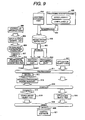
- FIG. 9 shows a development environment and a development procedure to implement a device driver generation method in an embodiment of the present invention.
- An identifier expanding part 192 and processing description part 180 in the device driver 120 which has been already created, are registered in step 901.
- a necessary identifier expanding part 192 and processing description part 180 are obtained from a device driver repository 902 in which they are stored.
- a hierarchical configuration generator 906 is then used to obtain a hierarchical configuration description part 908 in step 907.
- the hierarchical configuration description part 908, identifier expanding part 909, and processing description part 910 thus obtained undergo macro expansion by a preprocessor 911 in step 912. Accordingly, a processing description part 913, in which a hierarchical configuration is expanded according to the identifier expanding part 909 and hierarchical configuration description part 908, can be obtained from the processing description part 910 described by use of layers.
- the processing description part 913 resulting from the expansion has no hierarchical configuration, that is, comprises only a single layer, eliminating the overhead for inter-layer processing.
- a device driver object file 916 is obtained in step 915 in which compilation is performed by a compiler 914.
- the device driver object file 916 is linked by a linker 919 to an application object file 918, which results from compilation of an application source code 917, and control software 921 is then produced.
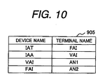
- FIG. 10 shows an example of an input/output terminal list 905.
- the input/output terminal list 905 shows correspondence between hardware devices and control unit terminals.
- this list is used to make the upper layer (L1) 160 correspond to a hardware device and the lower layer to correspond to hardware ports 131 to 133, FIG. 10 matches FIG. 5A. Accordingly, the hierarchical configuration generator 906 outputs the list in FIG. 5B.
- the processing description part 908 can be automatically generated from the input/output terminal list 905 on a computer, thereby increasing productivity.
- the hierarchical configuration generator 906, device driver repository 902, and compiler 914 can be implemented by use of a computer having input means, such as a keyboard, mouse, and network, an output means such as a CRT, and a storage means such as a hard disk drive.
- An electronic control unit in an engine controller mounted in an automobile requires high-speed processing and high reliability and is frequently subject to hardware modifications.
- inventive software generation method and software generation system intended for a microprocessor is used in such an electronic control unit, the burden of the developer can be greatly reduced and a high applicability can be expected.
Landscapes
- Engineering & Computer Science (AREA)
- General Engineering & Computer Science (AREA)
- Theoretical Computer Science (AREA)
- Software Systems (AREA)
- General Physics & Mathematics (AREA)
- Physics & Mathematics (AREA)
- Chemical & Material Sciences (AREA)
- Mechanical Engineering (AREA)
- Combustion & Propulsion (AREA)
- Automation & Control Theory (AREA)
- Microelectronics & Electronic Packaging (AREA)
- Computer Hardware Design (AREA)
- Stored Programmes (AREA)
Applications Claiming Priority (1)
| Application Number | Priority Date | Filing Date | Title |
|---|---|---|---|
| PCT/JP2004/018197 WO2006061884A1 (ja) | 2004-12-07 | 2004-12-07 | 自動車用制御装置とそのソフトウエア作成方法及びシステム |
Publications (2)
| Publication Number | Publication Date |
|---|---|
| EP1835366A1 true EP1835366A1 (de) | 2007-09-19 |
| EP1835366A4 EP1835366A4 (de) | 2014-08-13 |
Family
ID=36577714
Family Applications (1)
| Application Number | Title | Priority Date | Filing Date |
|---|---|---|---|
| EP04822576.7A Withdrawn EP1835366A4 (de) | 2004-12-07 | 2004-12-07 | Automobil-regler und softwareerstellungsverfahren und -system dafür |
Country Status (4)
| Country | Link |
|---|---|
| US (1) | US20080256522A1 (de) |
| EP (1) | EP1835366A4 (de) |
| JP (1) | JP4921175B2 (de) |
| WO (1) | WO2006061884A1 (de) |
Families Citing this family (2)
| Publication number | Priority date | Publication date | Assignee | Title |
|---|---|---|---|---|
| JP2009080566A (ja) * | 2007-09-25 | 2009-04-16 | Hitachi Ltd | 車両制御用プログラムおよびプログラム生成方法、プログラム生成装置、及び自動車用制御装置 |
| US8468332B2 (en) * | 2009-06-13 | 2013-06-18 | Kinglite Holdings Inc. | Dynamic link loading in extensible firmware interface compliant systems |
Family Cites Families (11)
| Publication number | Priority date | Publication date | Assignee | Title |
|---|---|---|---|---|
| JPS63181034A (ja) * | 1987-01-23 | 1988-07-26 | Nissan Motor Co Ltd | 制御プログラムの開発支援装置 |
| JPH03282935A (ja) * | 1990-03-30 | 1991-12-13 | Pfu Ltd | コンパイル処理装置及びコンパイル処理方式 |
| JPH05150960A (ja) * | 1991-11-26 | 1993-06-18 | Fujitsu Ltd | プリコンパイラ |
| JPH07277105A (ja) * | 1994-04-15 | 1995-10-24 | Hitachi Ltd | 自動車用制御装置 |
| JP3606654B2 (ja) * | 1995-10-30 | 2005-01-05 | 富士通株式会社 | コンパイラ装置 |
| US6122634A (en) * | 1996-11-12 | 2000-09-19 | International Business Machines Corporation | Fractal nested layout for hierarchical system |
| US6550052B1 (en) * | 1999-11-09 | 2003-04-15 | Daimlerchrysler Corporation | Software development framework for constructing embedded vehicle controller software |
| JP3941649B2 (ja) * | 2001-09-28 | 2007-07-04 | スズキ株式会社 | アルミニウム基材及びその表面処理方法 |
| US7571445B2 (en) * | 2001-11-29 | 2009-08-04 | Dell Products L.P. | System and method for dynamic device driver support in an open source operating system |
| JP3904485B2 (ja) * | 2002-06-27 | 2007-04-11 | 富士通テン株式会社 | 車輌制御プログラム開発システム、車輌制御装置、及び記憶媒体 |
| US7996825B2 (en) * | 2003-10-31 | 2011-08-09 | Hewlett-Packard Development Company, L.P. | Cross-file inlining by using summaries and global worklist |
-
2004
- 2004-12-07 US US11/792,366 patent/US20080256522A1/en not_active Abandoned
- 2004-12-07 EP EP04822576.7A patent/EP1835366A4/de not_active Withdrawn
- 2004-12-07 JP JP2006546575A patent/JP4921175B2/ja not_active Expired - Lifetime
- 2004-12-07 WO PCT/JP2004/018197 patent/WO2006061884A1/ja not_active Ceased
Also Published As
| Publication number | Publication date |
|---|---|
| WO2006061884A1 (ja) | 2006-06-15 |
| JPWO2006061884A1 (ja) | 2008-06-05 |
| US20080256522A1 (en) | 2008-10-16 |
| JP4921175B2 (ja) | 2012-04-25 |
| EP1835366A4 (de) | 2014-08-13 |
Similar Documents
| Publication | Publication Date | Title |
|---|---|---|
| CN103064403B (zh) | 一种ecu硬件在环仿真自动化测试方法和系统 | |
| US20140236384A1 (en) | Vehicle Control Software and Vehicle Control Apparatus | |
| EP2447832A1 (de) | Aufruf einer Instanz eines graphischen Modells mit einer nicht graphischen Instanz und Aufruf einer nicht graphischen Instanz eines graphischen Modells mit einer graphischen Instanz | |
| JPH06266563A (ja) | 複数同時オブジェクト・バージョンをサポートする効率的ルータ | |
| JPH0869447A (ja) | データ処理装置 | |
| KR20060123513A (ko) | 컴퓨터 프로그램의 구성 방법 | |
| EP1835366A1 (de) | Automobil-regler und softwareerstellungsverfahren und -system dafür | |
| Notkin et al. | Extension and Software Development. | |
| Hanselmann et al. | Production quality code generation from Simulink block diagrams | |
| US9558305B1 (en) | Automatic modeling, mapping, and code generation for homogeneous and heterogeneous platforms | |
| Dziurzanski et al. | Benchmarking, system design and case-studies for multi-core based embedded automotive systems | |
| JP2011238297A (ja) | 自動車用制御装置のソフトウエア作成方法 | |
| JP2007310565A (ja) | システムlsi検証装置及びシステムlsi検証プログラム | |
| JP7798331B2 (ja) | マイクロコンピュータ制御プログラムのシミュレーション方法及びそのためのシミュレーションシステム | |
| CN115373707A (zh) | 航天器实时系统内存受限条件下任务在线更新系统及方法 | |
| JP3046710B2 (ja) | プログラム作成装置 | |
| Conrad et al. | Towards a methodology for the design of hybrid systems in automotive electronics | |
| JP2025178177A (ja) | サポートされていない信号方式を処理するためのコンピュータ実装方法、制御プログラムを生成するためのコンピュータ実装方法、データ処理のための装置、コンピュータプログラム製品およびデータ担体 | |
| CN110701948B (zh) | 一种提高随动系统实时调试效率方法 | |
| JPH09179738A (ja) | オブジェクト指向言語処理方法及び処理装置 | |
| JP4919782B2 (ja) | 組込みコントローラ及び組込みコントローラ開発ツール | |
| JPH07175664A (ja) | コンパイラ装置 | |
| Schöbel-Theuer | On Variants of Genericity. | |
| KR100513027B1 (ko) | 맨 머신 랭귀지 구현 방법 | |
| Rodriguez et al. | PolyForth: an electronics engineer's programming tool |
Legal Events
| Date | Code | Title | Description |
|---|---|---|---|
| PUAI | Public reference made under article 153(3) epc to a published international application that has entered the european phase |
Free format text: ORIGINAL CODE: 0009012 |
|
| 17P | Request for examination filed |
Effective date: 20070709 |
|
| AK | Designated contracting states |
Kind code of ref document: A1 Designated state(s): DE |
|
| RIN1 | Information on inventor provided before grant (corrected) |
Inventor name: MAYAMA, KAZUNORIH Inventor name: TSUNEDOMI, KUNIHIKOH Inventor name: NARISAWA, FUMIOH |
|
| DAX | Request for extension of the european patent (deleted) | ||
| RBV | Designated contracting states (corrected) |
Designated state(s): DE |
|
| A4 | Supplementary search report drawn up and despatched |
Effective date: 20140715 |
|
| RIC1 | Information provided on ipc code assigned before grant |
Ipc: F02D 41/26 20060101ALI20140709BHEP Ipc: G06F 9/44 20060101ALI20140709BHEP Ipc: G05B 19/05 20060101AFI20140709BHEP |
|
| STAA | Information on the status of an ep patent application or granted ep patent |
Free format text: STATUS: THE APPLICATION HAS BEEN WITHDRAWN |
|
| 18W | Application withdrawn |
Effective date: 20141029 |