EP1835231A1 - Brûleur pour une chambre de combustion de turbine à gaz et procédé d'opération du brûleur - Google Patents
Brûleur pour une chambre de combustion de turbine à gaz et procédé d'opération du brûleur Download PDFInfo
- Publication number
- EP1835231A1 EP1835231A1 EP06005107A EP06005107A EP1835231A1 EP 1835231 A1 EP1835231 A1 EP 1835231A1 EP 06005107 A EP06005107 A EP 06005107A EP 06005107 A EP06005107 A EP 06005107A EP 1835231 A1 EP1835231 A1 EP 1835231A1
- Authority
- EP
- European Patent Office
- Prior art keywords
- burner
- lip portion
- pilot fuel
- face
- space
- Prior art date
- Legal status (The legal status is an assumption and is not a legal conclusion. Google has not performed a legal analysis and makes no representation as to the accuracy of the status listed.)
- Withdrawn
Links
Images


Classifications
-
- F—MECHANICAL ENGINEERING; LIGHTING; HEATING; WEAPONS; BLASTING
- F23—COMBUSTION APPARATUS; COMBUSTION PROCESSES
- F23D—BURNERS
- F23D17/00—Burners for combustion conjointly or alternatively of gaseous or liquid or pulverulent fuel
- F23D17/002—Burners for combustion conjointly or alternatively of gaseous or liquid or pulverulent fuel gaseous or liquid fuel
-
- F—MECHANICAL ENGINEERING; LIGHTING; HEATING; WEAPONS; BLASTING
- F23—COMBUSTION APPARATUS; COMBUSTION PROCESSES
- F23C—METHODS OR APPARATUS FOR COMBUSTION USING FLUID FUEL OR SOLID FUEL SUSPENDED IN A CARRIER GAS OR AIR
- F23C7/00—Combustion apparatus characterised by arrangements for air supply
- F23C7/002—Combustion apparatus characterised by arrangements for air supply the air being submitted to a rotary or spinning motion
-
- F—MECHANICAL ENGINEERING; LIGHTING; HEATING; WEAPONS; BLASTING
- F23—COMBUSTION APPARATUS; COMBUSTION PROCESSES
- F23D—BURNERS
- F23D14/00—Burners for combustion of a gas, e.g. of a gas stored under pressure as a liquid
- F23D14/20—Non-premix gas burners, i.e. in which gaseous fuel is mixed with combustion air on arrival at the combustion zone
- F23D14/22—Non-premix gas burners, i.e. in which gaseous fuel is mixed with combustion air on arrival at the combustion zone with separate air and gas feed ducts, e.g. with ducts running parallel or crossing each other
- F23D14/24—Non-premix gas burners, i.e. in which gaseous fuel is mixed with combustion air on arrival at the combustion zone with separate air and gas feed ducts, e.g. with ducts running parallel or crossing each other at least one of the fluids being submitted to a swirling motion
-
- F—MECHANICAL ENGINEERING; LIGHTING; HEATING; WEAPONS; BLASTING
- F23—COMBUSTION APPARATUS; COMBUSTION PROCESSES
- F23R—GENERATING COMBUSTION PRODUCTS OF HIGH PRESSURE OR HIGH VELOCITY, e.g. GAS-TURBINE COMBUSTION CHAMBERS
- F23R3/00—Continuous combustion chambers using liquid or gaseous fuel
- F23R3/28—Continuous combustion chambers using liquid or gaseous fuel characterised by the fuel supply
- F23R3/34—Feeding into different combustion zones
- F23R3/343—Pilot flames, i.e. fuel nozzles or injectors using only a very small proportion of the total fuel to insure continuous combustion
-
- F—MECHANICAL ENGINEERING; LIGHTING; HEATING; WEAPONS; BLASTING
- F23—COMBUSTION APPARATUS; COMBUSTION PROCESSES
- F23R—GENERATING COMBUSTION PRODUCTS OF HIGH PRESSURE OR HIGH VELOCITY, e.g. GAS-TURBINE COMBUSTION CHAMBERS
- F23R3/00—Continuous combustion chambers using liquid or gaseous fuel
- F23R3/28—Continuous combustion chambers using liquid or gaseous fuel characterised by the fuel supply
- F23R3/36—Supply of different fuels
-
- F—MECHANICAL ENGINEERING; LIGHTING; HEATING; WEAPONS; BLASTING
- F23—COMBUSTION APPARATUS; COMBUSTION PROCESSES
- F23C—METHODS OR APPARATUS FOR COMBUSTION USING FLUID FUEL OR SOLID FUEL SUSPENDED IN A CARRIER GAS OR AIR
- F23C2202/00—Fluegas recirculation
- F23C2202/40—Inducing local whirls around flame
-
- F—MECHANICAL ENGINEERING; LIGHTING; HEATING; WEAPONS; BLASTING
- F23—COMBUSTION APPARATUS; COMBUSTION PROCESSES
- F23D—BURNERS
- F23D2214/00—Cooling
Definitions
- the present invention relates to burner, in particular a gas turbine burner, as well as to a combustor, in particular a gas turbine combustor, and a method of operating the same.
- a fuel is burned to produce hot pressurised exhaust gases which are then fed to a turbine stage where they, while expanding and cooling, transfer momentum to turbine blades thereby imposing a rotational movement on a turbine rotor.
- Mechanical power of the turbine rotor can then be used to drive a generator for producing electrical power or to drive a machine.
- burning the fuel leads to a number of undesired pollutants in the exhaust gas which can cause damage to the environment. Therefore, it takes considerable effort to keep the pollutants as low as possible.
- One kind of pollutant is nitrous oxide (NO x ). The rate of formation of nitrous oxide depends exponentially on the temperature of the combustion flame. It is therefore attempted to reduce the temperature over the combustion flame in order to keep the formation of nitrous oxide as low as possible.
- Another kind of pollutants, hydrocarbons can result if a part of the fuel is not or not fully burnt in the combustor.
- the first is to use a lean stoichiometry, e.g. a fuel/air mixture with a low fuel fraction.
- the relatively small fraction of fuel leads to a combustion flame with a low temperature and thus to a low rate of nitrous oxide formation.
- the second measure is to provide a thorough mixing of fuel and air before the combustion takes place. The better the mixing is the more uniformly distributed the fuel is in the combustion zone. This helps to prevent hotspots in the combustion zone which would arise from relative local maxima in the fuel/air mixing ratio, i.e. zones with high fuel /air mixing ratio compared to the average fuel/air mixing ratio in the combustor.
- Modern gas turbine engines therefore use the concept of pre-mixing air and fuel in lean stoichiometry before the combustion of the fuel/air mixture.
- the pre-mixing takes place by injecting fuel into an air stream in a swirling zone of a combustor which is located upstream from the combustion zone.
- the swirling leads to a mixing of fuel and air before the mixture enters the combustion zone.
- a pilot fuel injection system is usually used to stabilise the combustion.
- Such a pilot fuel injection system is, e.g. disclosed in US 6,532,726 B2 .
- This document describes a combustor with uniform fuel/air premixing for low emissions combustion. It comprises an air inlet duct and a swirler disposed in the air inlet duct.
- the swirler is arranged such that in-taken air streams into a pre-combustion chamber in a direction more or less perpendicular to a main combustor axis.
- the swirler is arranged around the central part of the pre-chamber.
- a burner head face, which forms the upstream end of the pre-chamber, comprises four pilot fuel inlet openings which are arranged symmetrically at four positions off centre of the central axis of the burner. This configuration is beneficial for control of the nozzle temperature.
- the pilot fuel flow rate is high and therefore the propensity for forming fuel rich NO x -producing pockets in the combustion zone is increased.
- An inventive burner which may, in particular be a gas turbine combustor, comprises a burner face, a liquid fuel injection system and a liquid pilot fuel injection system.
- the liquid pilot fuel injection system comprises a lip portion which overlaps in parallel a circumferential section of the burner face so as to leave a space between the lip portion and the burner face.
- One or more air supply passages lead to the space between the lip portion and the burner face.
- one or more liquid pilot fuel supply passages lead into the space between the lip portion and the burner face and/or through the lip portion into a space encircled by the lip portion.
- the present invention provides a number of advantages over the combustor described in US 6,532,726 B2 .
- the one or more liquid fuel supply passages may lead into the space between the lip portion and the burner face and/or through the lip portion into the space encircled by the lip portion via one or more outlet openings which may be located in the burner face where it is overlapped by the lip portion and/or in the lip portion. If the outlet openings are arranged in the burner face where it is overlapped by the lip portion the fraction of liquid fuel coming into contact with the burner face prior to reaching the intended atomisation region between the lip and the burner face can be kept low. Moreover, an even flow of atomised droplets near the ignitor could ensure higher ignition reliability with this design.
- the lip portion and/or the burner face may be made at least partly from a laminate structure into which at least those parts of the liquid pilot fuel supply passages are integrated which adjoin the outlet openings.
- This configuration provides the possibility of providing spray nozzles for extremely fine atomised spray using only hydraulic pressure.
- drop sizes can be realised which are below usual impact atomisers, it can ensure that all liquid fuel is so injected as to not come into contact with the burner face prior to reaching the intended atomisation region.
- a preheating of the liquid pilot fuel streaming through the laminate structure can be realised. By the preheating the liquid pilot fuel may at least partly evaporate.
- the present invention can, in particular, be implemented with combustors which are designed so as to be operated with either liquid or gaseous fuel.
- the inventive burner comprises a gaseous fuel injection system and a gaseous pilot fuel injection system which includes one or more gaseous pilot fuel supply passages.
- a downstream part of the one or more gaseous pilot fuel supply passages i.e. a part which adjoins the outlet openings, is then identical to a downstream part of the one or more air supply passages of the liquid pilot fuel supply passage.
- the passages for supplying gaseous pilot fuel may be used to provide the atomising air for the liquid pilot fuel injection.
- Such a burner advantageously comprises an associated switch mechanism for switching between gaseous fuel supply and air supply through the identical downstream parts.
- Feeding of the air to the gaseous pilot fuel supply passages may, e.g. be realised by one or more bleed pipes which connect the passages to an air supply, in particular, to a compressor section of the gas turbine engine.
- conventional liquid pilot fuel supply passages i.e. supply passages leading to openings in a section of the burner face which is not overlapped by the lip, as described, for example, in US 6,532,726 B2 , may be additionally present.
- the pilot fuel injection can be optimised.
- An inventive combustor which may, in particular, be a gas turbine combustor, comprises an inventive burner, a combustion chamber (which may also be called a main chamber) and a transition section (which may also be called a pre-chamber) which is arranged in flow series between the burner and the combustion chamber.
- the burner face forms the upstream end face of the transition section.
- the transition section may be implemented as a one part continuation of the burner towards the combustion chamber, as a one part continuation of the combustion chamber towards the burner, or as a separate part between the burner and the combustion chamber.
- a method of operating a combustor in particular a gas turbine engine combustor, which comprises a burner, a combustion chamber (which may also be called main chamber) and a transition section (which may also be called pre-chamber) where the transition section is arranged in flow series between the burner and the combustion chamber is also provided.
- a gas turbine engine combustor which comprises a burner, a combustion chamber (which may also be called main chamber) and a transition section (which may also be called pre-chamber) where the transition section is arranged in flow series between the burner and the combustion chamber is also provided.
- the burner comprises a burner face which forms the upstream end face of the transition section, a liquid fuel injection system, a liquid pilot fuel injection system, a gaseous fuel injection system and a gaseous pilot fuel injection system which comprises a lip portion overlapping in parallel a circumferential section of the burner face so as to leave a space between the lip portion and the burner face and one or more gaseous pilot fuel supply passages leading into the space between the lip portion and the burner face.
- air is led into the space between the lip portion and the burner face through at least a downstream part of the one or more gaseous pilot fuel supply passages so as to form an air stream streaming through said space when the combustor is operated in a liquid fuel mode.
- liquid pilot fuel is injected into the air stream streaming through the space between the lip portion and the burner face and/or liquid pilot fuel is injected through the lip portion into an air stream streaming through the space encircled by the lip portion.
- the liquid pilot fuel is at least partially preheated before it is injected into the air stream streaming through the space between the lip portion and the burner face and/or before it is injected through the lip portion into the air stream streaming through the space encircled by the lip portion.
- Additional pilot fuel may also be injected directly into the transition section and/or the combustion chamber through outlet openings in a section of the burner face where it is not overlapped by the lip portion.
- the effect of the pilot fuel injection may be optimised.
- Figure 1 schematically shows a gas turbine engine combustor according to the invention.
- Figure 2 shows a part of the burner of the combustor shown in Figure 1 in a partly sectional perspective view.
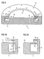
- FIGS 3a and 3b show details from Figure 2.
- Figure 4 shows an alternative embodiment to Figures 3a and 3b.
- FIG. 5 shows another alternative embodiment.
- Figure 6 shows a modification of the embodiment shown in Fig. 5.
- the combustor comprises a burner 10, including a burner head portion 11 attached to a radial inflow swirler portion 12, a transition section 13, and a main combustion chamber 14.
- the main chamber 14 has a diameter larger than that of the pre-chamber 13.
- the transition piece 13 may also be referred to as a pre-chamber in regard to the combustion chamber.
- the combustor shows, in general, a rotational symmetry with respect to a rotational axis S.
- compressed air flowing in the direction of the arrows 15 shown in Figure 1, is supplied to the combustor (usually from a gas turbine compressor) and enters the pre-chamber 13 in a direction substantially perpendicular to the symmetry axis S.
- a tangential component relative to a circle centred around a symmetry axis is imposed to the inflowing compressed air 15 by the swirler 12.
- the air taken in through the swirler 12 mixes with fuel injected into the swirler by fuel injectors 23, 27 and, on arriving in the pre-chamber 13, the mixture is ignited by means such as an electric ignitor unit 17. Once lit, the flame continues to burn without further assistance from such ignitor.
- the combustor shown in Figure 1 may either be operated with gaseous or liquid fuel.
- pilot gas is injected through a gaseous pilot fuel injection system comprising an annular pilot gas gallery 19 which is in flow connection via either a series of spaced-apart openings 32 or a continuous annular duct, to inject pilot gas to the underside of a directing means in the form of circumferential lip 20 extending radially inwards towards the symmetry axis S of the combustor.
- the pilot gas is fed from connectors 18 through interconnecting ducts, as shown in Figure 1. The lip deflects the pilot gas across a central portion 22 of the burner face 16, i.e. radially inwards in a direction generally normal to the symmetry axis S.
- the pilot gas mixes with incoming compressed air 15 and main gas-fuel exiting the swirler 12.
- the main gas fuel is introduced into the swirler by openings 23 which are located in the burner face 16 at the swirler air inlet region, i.e. in a radially outer part of the burner face 16 and are fed by connectors 24 through interconnecting ducts, as shown.
- the combustion flame envelope represented by the boundary line F and the flame front face FF.
- the flame front face FF is created by recirculation of fluid entering the combustion chamber along the radially outer parts of the chamber back along the central part of the chamber (along symmetry axis S) towards the burner face 16 and then back again towards the main chamber 14.
- the front face FF itself is the point at which the axial flow in the direction of the burner 10 turns back towards the main chamber 14.
- the burner 10 may also be operated with liquid fuel. Therefore, it comprises a liquid fuel injection system and a liquid pilot fuel injection system.
- the main liquid fuel injection system is formed from injection openings 27 in the burner face 16 which are located radially inwards with respect to the gas fuel inlet holes 23 at the swirler air inlet region.
- the liquid fuel injection openings 27 are fed from connectors 28 through interconnecting ducts.
- the liquid pilot fuel injection system (see Figure 2) comprises four liquid pilot fuel openings 25 which are fed from connectors 26 through interconnecting ducts, as shown in Figure 1.
- the liquid pilot fuel injections openings 25 are located in the central part 22 of the burner face 16. They are located symmetrically around the symmetry axis S.
- the liquid pilot fuel injection system comprises second liquid pilot fuel injection openings 50 which are located in a section of the central part 22 of the burner face 16 which is overlapped by the lip 20 of the gaseous pilot fuel injection system (see Figures 3a and 3b). These injection openings 50 are fed through ducts 52 extending through the burner head 11.
- liquid pilot fuel is, on the one hand, introduced into the pre-chamber through the first liquid pilot fuel injection openings 25 and, on the other hand, through the second liquid pilot fuel injection openings 50.
- air instead of gaseous fuel is injected into the pre-chamber 13 through the gallery 19 and the openings 32.
- the air is fed to the gallery 19 by bleed passages interconnecting the gallery 19 to a compressor section of the gas turbine engine.
- Pilot fuel injected through the openings 50 is introduced into the air stream streaming through the space 54 between the lip 20 and the overlapped part of the burner face 16. Thereby, an atomisation of the liquid pilot fuel introduced through the openings 50 takes place before it leaves the space 54.
- a second embodiment of the liquid pilot fuel injection system is shown in Figure 4. While, in the first embodiment, the second pilot fuel injection openings 50 are fed through ducts 52 extending through the gallery 19 and the burner head 11, in the second embodiment, shown in Figure 4, a macro-laminate structure is used for feeding second liquid pilot fuel injection openings 150.
- the laminate structure forms micro ducts 152 extending from a central duct 154 located in the burner heads 11 centre to the openings 150. This configuration improves the atomisation of the injected liquid fuel in the air stream in the space 54. In the central duct 154 and more so in the micro ducts 152 a preheating of the pilot fuel takes place which may also lead to an at least partial evaporation of the pilot fuel.
- the second liquid pilot fuel injections openings 250 are located in the face of the lip 20 which is directed to the burner face 16 rather than in the burner face 16 itself.
- the use of a macro-laminate structure of the lip in the configuration shown in Figure 5 in which micro ducts 252 lead to the injection openings 250 in the lips face ensure that all fuel so injected does not come into contact with the burner face 16 prior to reaching the intended atomisation region of the space 54 between the lip 20 and the burner face 16.
- micro ducts 256 may lead to injection openings 254 located in the front face 21 of the lip 20, i.e. the face which is directed towards the centre of the burner 10, instead to injection openings 250 located in the face of the lip 20 which is directed to the burner face 16.
- injection openings 250 located in the face of the lip 20 which is directed to the burner face 16.
- the micro ducts 250 leading to injection openings 250 located in the face of the lip 20 which is directed to the burner face 16 and/or the micro ducts 256 leading to the injection openings 254 located in the front face 21 of the lip 20 may extend from a central duct 154, as in the second embodiment. Note that a combination of the openings and micro ducts of the second embodiment with the openings and micro ducts of the third embodiment and its modifications is possible.
- the performance of liquid pilot fuel injection can be improved with minimal impact on the gaseous fuel operation of the burner.
- the annular gallery 19, which is used in the gaseous fuel mode for feeding the pilot gas is, in the liquid fuel mode, used for feeding the atomisation air for atomising the liquid pilot fuel, the design changes which are necessary with respect to a conventional burner as described in US 6,532,726 B2 to implement the inventive combustor concept are minimal.
Priority Applications (2)
| Application Number | Priority Date | Filing Date | Title |
|---|---|---|---|
| EP06005107A EP1835231A1 (fr) | 2006-03-13 | 2006-03-13 | Brûleur pour une chambre de combustion de turbine à gaz et procédé d'opération du brûleur |
| PCT/EP2007/050784 WO2007104599A1 (fr) | 2006-03-13 | 2007-01-26 | Brûleur, en particulier pour une chambre de combustion à turbine à gaz, et méthode d'utilisation d'un brûleur |
Applications Claiming Priority (1)
| Application Number | Priority Date | Filing Date | Title |
|---|---|---|---|
| EP06005107A EP1835231A1 (fr) | 2006-03-13 | 2006-03-13 | Brûleur pour une chambre de combustion de turbine à gaz et procédé d'opération du brûleur |
Publications (1)
| Publication Number | Publication Date |
|---|---|
| EP1835231A1 true EP1835231A1 (fr) | 2007-09-19 |
Family
ID=36778395
Family Applications (1)
| Application Number | Title | Priority Date | Filing Date |
|---|---|---|---|
| EP06005107A Withdrawn EP1835231A1 (fr) | 2006-03-13 | 2006-03-13 | Brûleur pour une chambre de combustion de turbine à gaz et procédé d'opération du brûleur |
Country Status (2)
| Country | Link |
|---|---|
| EP (1) | EP1835231A1 (fr) |
| WO (1) | WO2007104599A1 (fr) |
Cited By (5)
| Publication number | Priority date | Publication date | Assignee | Title |
|---|---|---|---|---|
| EP2246617A1 (fr) * | 2009-04-29 | 2010-11-03 | Siemens Aktiengesellschaft | Brûleur pour moteur de turbine à gaz |
| EP2629008A1 (fr) * | 2012-02-15 | 2013-08-21 | Siemens Aktiengesellschaft | Injection de carburant inclinée dans une fente de tourbillonnement |
| EP3184898A1 (fr) * | 2015-12-23 | 2017-06-28 | Siemens Aktiengesellschaft | Chambre de combustion pour turbine à gaz |
| EP3301374A1 (fr) * | 2016-09-29 | 2018-04-04 | Siemens Aktiengesellschaft | Ensemble de bruleur pilote dote d'une alimentation d'air pilote |
| EP3376109A1 (fr) * | 2017-03-16 | 2018-09-19 | General Electric Company | Buse à combustible bicombustible avec une extrémité injectant du combustible liquide |
Families Citing this family (5)
| Publication number | Priority date | Publication date | Assignee | Title |
|---|---|---|---|---|
| DE102011082884A1 (de) * | 2011-09-16 | 2013-03-21 | Man Diesel & Turbo Se | Brenner und Gasturbine mit einem solchen Brenner |
| US9518475B2 (en) | 2013-10-28 | 2016-12-13 | General Electric Company | Re-use of internal cooling by medium in turbine hot gas path components |
| EP2942563A1 (fr) | 2014-05-09 | 2015-11-11 | Siemens Aktiengesellschaft | Élément de tourbillonnement d'un brûleur de moteur de turbine à gaz, brûleur de moteur de turbine à gaz et moteur de turbine à gaz |
| DE102014211755B4 (de) * | 2014-06-18 | 2017-12-14 | Technische Universität Bergakademie Freiberg | Vergaserkopf für die Partialoxidation von gasförmigen und flüssigen Vergasungsstoffen |
| US10961967B1 (en) | 2017-12-12 | 2021-03-30 | Microfabrica Inc. | Fuel injector systems, fuel injectors, fuel injector nozzles, and methods for making fuel injector nozzles |
Citations (5)
| Publication number | Priority date | Publication date | Assignee | Title |
|---|---|---|---|---|
| GB2104641A (en) * | 1981-07-28 | 1983-03-09 | Cherny Anatoly A | Method and apparatus for feeding fuel into an oxidizing atmosphere during its combustion |
| US5450724A (en) * | 1993-08-27 | 1995-09-19 | Northern Research & Engineering Corporation | Gas turbine apparatus including fuel and air mixer |
| EP0728989A2 (fr) * | 1995-01-13 | 1996-08-28 | European Gas Turbines Limited | Appareil de combustion pour moteur de turbine à gaz |
| US20010027637A1 (en) * | 1998-01-31 | 2001-10-11 | Eric Roy Norster | Gas-turbine engine combustion system |
| DE10331575A1 (de) * | 2003-07-11 | 2005-02-10 | Webasto Thermosysteme Gmbh | Brenner für ein Heizgerät mit einer Brennstoffdüse |
-
2006
- 2006-03-13 EP EP06005107A patent/EP1835231A1/fr not_active Withdrawn
-
2007
- 2007-01-26 WO PCT/EP2007/050784 patent/WO2007104599A1/fr active Application Filing
Patent Citations (6)
| Publication number | Priority date | Publication date | Assignee | Title |
|---|---|---|---|---|
| GB2104641A (en) * | 1981-07-28 | 1983-03-09 | Cherny Anatoly A | Method and apparatus for feeding fuel into an oxidizing atmosphere during its combustion |
| US5450724A (en) * | 1993-08-27 | 1995-09-19 | Northern Research & Engineering Corporation | Gas turbine apparatus including fuel and air mixer |
| EP0728989A2 (fr) * | 1995-01-13 | 1996-08-28 | European Gas Turbines Limited | Appareil de combustion pour moteur de turbine à gaz |
| US20010027637A1 (en) * | 1998-01-31 | 2001-10-11 | Eric Roy Norster | Gas-turbine engine combustion system |
| US6532726B2 (en) | 1998-01-31 | 2003-03-18 | Alstom Gas Turbines, Ltd. | Gas-turbine engine combustion system |
| DE10331575A1 (de) * | 2003-07-11 | 2005-02-10 | Webasto Thermosysteme Gmbh | Brenner für ein Heizgerät mit einer Brennstoffdüse |
Cited By (15)
| Publication number | Priority date | Publication date | Assignee | Title |
|---|---|---|---|---|
| US8739545B2 (en) | 2009-04-29 | 2014-06-03 | Siemens Aktiengesellschaft | Burner for a gas turbine engine |
| EP2246617A1 (fr) * | 2009-04-29 | 2010-11-03 | Siemens Aktiengesellschaft | Brûleur pour moteur de turbine à gaz |
| US9810433B2 (en) | 2012-02-15 | 2017-11-07 | Siemens Aktiengesellschaft | Inclined fuel injection of fuel into a swirler slot |
| WO2013120558A1 (fr) * | 2012-02-15 | 2013-08-22 | Siemens Aktiengesellschaft | Injection inclinée de carburant dans une fente de coupelle de turbulence |
| EP2629008A1 (fr) * | 2012-02-15 | 2013-08-21 | Siemens Aktiengesellschaft | Injection de carburant inclinée dans une fente de tourbillonnement |
| EP3184898A1 (fr) * | 2015-12-23 | 2017-06-28 | Siemens Aktiengesellschaft | Chambre de combustion pour turbine à gaz |
| WO2017108454A1 (fr) * | 2015-12-23 | 2017-06-29 | Siemens Aktiengesellschaft | Chambre de combustion pour turbine à gaz |
| CN108431503A (zh) * | 2015-12-23 | 2018-08-21 | 西门子股份公司 | 用于燃气轮机的燃烧器 |
| EP3301374A1 (fr) * | 2016-09-29 | 2018-04-04 | Siemens Aktiengesellschaft | Ensemble de bruleur pilote dote d'une alimentation d'air pilote |
| WO2018060098A1 (fr) * | 2016-09-29 | 2018-04-05 | Siemens Aktiengesellschaft | Ensemble brûleur pilote doté d'alimentation en air pilote |
| CN109804201A (zh) * | 2016-09-29 | 2019-05-24 | 西门子股份公司 | 具有引燃空气供应的引燃器组件 |
| CN109804201B (zh) * | 2016-09-29 | 2021-06-04 | 西门子股份公司 | 具有引燃空气供应的引燃器组件 |
| US11371705B2 (en) | 2016-09-29 | 2022-06-28 | Siemens Energy Global GmbH & Co. KG | Pilot burner assembly with pilot-air supply |
| EP3376109A1 (fr) * | 2017-03-16 | 2018-09-19 | General Electric Company | Buse à combustible bicombustible avec une extrémité injectant du combustible liquide |
| US10697639B2 (en) | 2017-03-16 | 2020-06-30 | General Electric Compamy | Dual-fuel fuel nozzle with liquid fuel tip |
Also Published As
| Publication number | Publication date |
|---|---|
| WO2007104599A1 (fr) | 2007-09-20 |
Similar Documents
| Publication | Publication Date | Title |
|---|---|---|
| EP1835231A1 (fr) | Brûleur pour une chambre de combustion de turbine à gaz et procédé d'opération du brûleur | |
| US7716931B2 (en) | Method and apparatus for assembling gas turbine engine | |
| EP1431543B1 (fr) | Injecteur | |
| US6354072B1 (en) | Methods and apparatus for decreasing combustor emissions | |
| US6983605B1 (en) | Methods and apparatus for reducing gas turbine engine emissions | |
| EP1193449B1 (fr) | Ensemble de vrilles annulaires | |
| US7059135B2 (en) | Method to decrease combustor emissions | |
| US8099940B2 (en) | Low cross-talk gas turbine fuel injector | |
| EP2206958A2 (fr) | Procédé et appareil pour l'injection de carburant dans un moteur à turbine | |
| US20090272117A1 (en) | Burner | |
| CA2516753C (fr) | Methodes et dispositif de reduction des emissions d'une turbine a gaz | |
| JP2003262336A (ja) | ガスタービン燃焼器 | |
| EP1847778A1 (fr) | Système de combustion à prémélange d'une turbine à gaz et son procédé de fonctionnement | |
| JP2008190855A (ja) | ガスタービンエンジン燃焼器のミキサアセンブリ用センターボディ | |
| US6862889B2 (en) | Method and apparatus to decrease combustor emissions | |
| US8465276B2 (en) | Burner for fluid fuels and method for operating such a burner | |
| CN110878947A (zh) | 燃气轮机燃烧器 | |
| EP2664854B1 (fr) | Système de combustion secondaire | |
| JP5896443B2 (ja) | 燃料ノズル | |
| EP1243854B1 (fr) | Injecteur de carburant | |
| EP1994334B1 (fr) | Chambre de combustion et méthode d'utilisation d'une chambre de combustion |
Legal Events
| Date | Code | Title | Description |
|---|---|---|---|
| PUAI | Public reference made under article 153(3) epc to a published international application that has entered the european phase |
Free format text: ORIGINAL CODE: 0009012 |
|
| AK | Designated contracting states |
Kind code of ref document: A1 Designated state(s): AT BE BG CH CY CZ DE DK EE ES FI FR GB GR HU IE IS IT LI LT LU LV MC NL PL PT RO SE SI SK TR |
|
| AX | Request for extension of the european patent |
Extension state: AL BA HR MK YU |
|
| AKX | Designation fees paid | ||
| REG | Reference to a national code |
Ref country code: DE Ref legal event code: 8566 |
|
| STAA | Information on the status of an ep patent application or granted ep patent |
Free format text: STATUS: THE APPLICATION IS DEEMED TO BE WITHDRAWN |
|
| 18D | Application deemed to be withdrawn |
Effective date: 20080320 |