EP1834726B1 - Electric resistance welding gun - Google Patents
Electric resistance welding gun Download PDFInfo
- Publication number
- EP1834726B1 EP1834726B1 EP06380047A EP06380047A EP1834726B1 EP 1834726 B1 EP1834726 B1 EP 1834726B1 EP 06380047 A EP06380047 A EP 06380047A EP 06380047 A EP06380047 A EP 06380047A EP 1834726 B1 EP1834726 B1 EP 1834726B1
- Authority
- EP
- European Patent Office
- Prior art keywords
- welding gun
- arm
- linear actuator
- pivot shaft
- pivot
- Prior art date
- Legal status (The legal status is an assumption and is not a legal conclusion. Google has not performed a legal analysis and makes no representation as to the accuracy of the status listed.)
- Not-in-force
Links
Images


Classifications
-
- B—PERFORMING OPERATIONS; TRANSPORTING
- B23—MACHINE TOOLS; METAL-WORKING NOT OTHERWISE PROVIDED FOR
- B23K—SOLDERING OR UNSOLDERING; WELDING; CLADDING OR PLATING BY SOLDERING OR WELDING; CUTTING BY APPLYING HEAT LOCALLY, e.g. FLAME CUTTING; WORKING BY LASER BEAM
- B23K11/00—Resistance welding; Severing by resistance heating
- B23K11/30—Features relating to electrodes
- B23K11/31—Electrode holders and actuating devices therefor
- B23K11/314—Spot welding guns, e.g. mounted on robots
Definitions
- the present invention relates to an electrical resistance welding gun, especially for spot welding, of the type comprising a passive arm holding a first electrode and a moving arm holding a second electrode, wherein the moving arm is mounted to pivot with respect to the fixed arm in order to close and open the welding gun.
- a type of electrical resistance welding gun comprising a pair of electrode-holding arms, one of which is passive and remains fixed in place with respect to a base support during the welding operation and the other is active and is mounted to pivot about a rotation axis with respect to the passive arm.
- a main pneumatic cylinder has a casing connected to an extension of the passive arm and a rod connected to the active arm, so that operation of said main pneumatic cylinder causes the active arm to pivot between an open position, in which a tip of the electrode on the active arm is separated from a tip of the electrode on the passive arm, and a closed position, in which said tip of the electrode on the active arm is able to press a work piece against said tip of the electrode on the passive arm in order to perform a welding operation.
- the welding gun includes a transformer connected to electric power supply means adapted to provide a welding current to the electrodes when the active arm is in said closed position.
- Document ES-A-1055232 describes a welding gun of the type described above, in which the passive arm is mounted so that it can also rotate a certain angle about the mentioned rotation axis and a secondary pneumatic cylinder has a casing connected to the base support and a rod connected to the passive arm. Operation of said secondary pneumatic cylinder produces a certain pivoting of the assembly formed by both passive and active arms without altering the relative position between them, which enables compensation of the welding gun position at the moment of closing for welding.
- the main pneumatic cylinder has a double piston that allows an approach run and a short total closing and pressure run to perform the welding. However, the maximum aperture reached between electrodes, even after an opening run of both pistons, is limited and it only allows overcoming small obstacles existing on the parts to be welded between the base support of the welding gun and the electrodes.
- Document ES-A-1043749 describes an electrical resistance welding gun, the general structure of which is similar to that described in the previously cited document ES-A-1055232 , with the difference that here, each of the two arms has a proximal portion formed by two plates facing each other, with a plurality of aligned holes adapted for the installation of fixing screws for securing a distal portion of the respective arm.
- the multiplicity of such holes permits selectively mounting arms of different lengths and working depths, although the maximum opening angle remains unvaried. To a certain extent, this construction contributes to overcoming obstacles, in that for equal opening angles the maximum gap between the electrodes is increased. However, the maximum opening angle is limited.
- the welding guns of the two previously cited documents are adapted to be manipulated by a robot.
- the base body is coupled to an arm or moving member of the robot and the welding gun is connected to a control unit associated with said robot so that it executes an automatic welding gun handling program, including automatic command of positioning, closing, welding and opening operations.
- Patent ES-A-2215009 describes a welding gun of the type described above, which is adapted to be manually handled.
- the base body of the welding gun is linked to a counter-weighted suspension system that permits manual vertical movements of the welding gun with a moderate effort.
- the suspension system permits movements of the welding gun in at least one horizontal direction and rotation of the welding gun about three orthogonal axes.
- One or more handles are connected to the base body of the welding gun, at least one of which including command elements for controlling welding operations.
- this type of manually operated welding gun has the passive arm fixed with respect to the base support since any possible obstacles on the parts to be welded are easily dealt with by manually manipulating the welding gun.
- the maximum opening angle is limited.
- Patent JP-A-63299866 describes an electrical resistance welding gun that comprises a base support and a lower arm that is pivotingly supported on the base support by a first articulation pin.
- a link is pivotingly supported on said lower arm by a second articulation pin and the casing of a pneumatic cylinder is pivotingly supported on said lower arm by a third articulation pin.
- An upper arm is pivotingly connected at the end of the cylinder rod by means of a fourth articulation pin.
- a fifth articulation pin which is inserted into a first elongated hole formed in the link
- a sixth articulation pin which is inserted in a second elongated hole formed in the link and can fit into a cradle formed in the base
- the sixth pin is located close to the fourth pin and the second articulation pin is located in an intermediate area between the electrode on the upper arm and the fourth pin.
- the upper arm and the link integer into each other and rotate together about the second articulation pin, moving the sixth pin along the length of the third elongated hole and out of the cradle to close the welding gun and perform a welding operation.
- the mechanism of the cited Japanese patent a significantly large maximum open angle can be achieved.
- the mechanism employed is very complex compared to the welding guns commonly used in the industry.
- a kinematic chain that includes up to four articulation pins, two of which sliding in corresponding elongated holes, in addition to the two articulation pins that connect the cylinder casing and rod with the passive and active arms respectively.
- the large number of articulations, together with the relatively large forces to which they are subjected makes the mechanism prone to play and/or maladjustments appearing that could lead to imprecise welding operations.
- this welding gun could likely to be costly in both manufacturing and maintenance.
- One object of the present invention is to provide an electric resistance welding gun provided with closing and opening movements between open and closed positions to perform normal spot welding operations, and additional extra-opening movements between said open position and an extra-open position in order to perform a positioning of the welding gun capable of overcoming relatively large obstacles in the pieces to be welded.
- an electrical resistance welding gun comprising in combination a base support, a passive arm holding a first electrode, said passive arm being mounted on said base support; an active arm holding a second electrode, said active arm being mounted to pivot about a pivot shaft with respect to the passive arm; a first linear actuator having an extendible rod connected to the active arm by means of a first articulation pin, said linear actuator being operable to pivot the active arm about said pivot shaft between an open position and a closed position; electrical power supply means adapted to provide a welding current to the first and second electrodes when the active arm is in said closed position; guiding means to guide a movement of the pivot shaft with respect to the passive arm along a curved path having its centre at said first articulation pin when said extendible rod of the first linear actuator is in a retracted position; and a second linear actuator having an extendible rod connected to the active arm by means of a second articulation pin, said second linear actuator being operable to pivot the active arm about the first articulation pin
- the active arm pivots on the pivot shaft to carry out closing and opening operations for welding under the action of the first linear actuator, as it would do in most of the prior art welding guns.
- the active arm is able to pivot about the first articulation pin provided between the active arm and the rod end of the first linear actuator under the action of the second linear actuator in order to open the welding gun to an extra-open position.
- the mentioned guiding means are provided along which the pivot shaft may be moved when the active arm shifts from the open position to the extra-open position and vice versa.
- the welding gun preferably incorporates retaining means operated by actuators to secure the position of the pivot shaft during the closing and opening operations for welding.
- the welding gun in accordance with the present invention can be adapted for manual or robotic operation.
- the passive arm is fixed with respect to the base support and the casings of the first and second linear actuators are connected either to the base support or to the passive arm, which form a same structure, by means of respective articulation shafts.
- the passive arm is mounted to pivot about the pivot shaft with respect to the base support and a third linear actuator, or compensation actuator, is installed between the passive arm and the base support in order to produce small rotations of the passive arm with respect to the base support.
- the casings of the first and second linear actuators are connected to the passive arm by means of respective articulation shafts so that the rotation of the passive arm driven by the third linear actuator is produced without altering the relative positions of the active and passive arms.
- These small rotations of the passive arm are used to rectify the welding gun position when it closes for welding operation depending on which of the two electrodes first makes contact with the pieces to be welded so as to avoid deformation in the pieces to be welded caused by the movements of the electrodes. In the welding gun adapted for manual operation, these small rotations of the passive arm are not necessary because the welder operates the welding gun so that the passive arm makes first contact and then orders for the active arm to close.
- the term "passive arm” is used to designate that of the two arms of the welding gun that at the moment of welding, i.e. when one electrode is pressed against the other with interposition of the pieced to be welded while a welding current is applied, remains fixed with respect to the base support and acts as an anvil or backing plate, although in some welding gun types adapted for robotic operation the third linear actuator can make small corrections to the passive arm position with respect to the base support immediately before or during welding to prevent deformation in the pieces to be welded.
- active arm is used to designate the other of the two arms of the welding gun, which is pushed towards the passive arm with respect to the base body during welding.
- the welding gun of the present invention in addition to the habitual closing and opening welding movements between an open position prior to welding, and a closed welding position, the welding gun of the present invention also permits extra-open movements in order to facilitate a positioning of the welding gun overcoming relatively large obstacles located on the pieces to be welded between the electrodes and the base support. Moreover, this extra-open possibility is achieved in a relatively simple manner, without compromising welding gun robustness and precision, especially during welding operations.
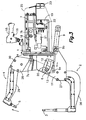
- FIGs. 1 to 3 show an electrical resistance welding gun in accordance with an exemplary embodiment of the present invention that is adapted for manual operation.
- the welding gun comprises a base support 1, a passive arm 2 that carries a first electrode 3 and an active arm 4 that carries a second electrode 5.
- the mentioned passive arm 2 is fixed to said base support 1 so that the base support 1 and the passive arm 2 form a same structure.
- the mentioned active arm 4 is mounted to pivot about a pivot shaft 6 with respect to the passive arm 2.
- a first liner actuator 7 has an extendible rod connected to the active arm 4 by a first articulation pin 7a and a casing connected to an appendix 18 forming part of the base support 1 by means of a first articulation shaft 7b, and the pivot shaft 6 is associated with guiding means 20 adapted to guide movement of the pivot shaft 6 with respect to the passive arm 2 in a curved path having its centre at said first articulation pin 7a when said extendible rod of the first linear actuator 7 is in a retracted position. Consequently, when the extendible rod of the first linear actuator 7 is in said retracted position (shown in Fig. 1 ) the active arm 4 is able to pivot about the first articulation pin 7a.
- a second linear actuator 9 has an extendible rod connected to the active arm 4 by means of a second articulation pin 9a and a casing connected to the passive arm 2 by means of a second articulation shaft 9b.
- the casing of the second linear actuator 9 could be connected to the base support 1 and/or the casing of the first linear actuator 7 could be connected to the passive arm 2 with an equivalent result, since the base support 1 and the passive arm 2 are mutually attached.
- the position of the passive and active arms 2, 4, shown in Fig. 1 is a neutral open position, ready to carry out closing and opening operations for spot welding.
- An action of the first linear actuator 7 for extending its rod from the position shown in Fig. 1 to the position shown in Fig. 2 makes the active arm 4 to pivot about said pivot shaft 6 from said open position to a closed position.
- this closed position shown in Fig. 2
- the continued force of the first linear actuator 7 is transmitted to the second electrode 5, which exerts considerable pressure on pieces to be welded (not shown) supported on the first electrode 3, which acts as an anvil or backing plate.
- the welding gun is fitted with electrical power supply means adapted to provide a high intensity welding current to the first and second electrodes 3, 5 when the active arm 4 is in the closed position shown in Fig. 2 .
- the mentioned electrical power supply means include a transformer 19 installed on the support base 1, as well as a connection port for connection to an external electrical power supply and a corresponding wiring (not shown). Subsequent action of the first linear actuator 7 in an opposite direction to take its rod to the retracted position makes the active arm 4 to pivot about the pivot shaft 6 from the closed position shown in Fig. 2 again to the neutral open position, shown in Fig. 1 .
- an action of the second linear actuator 9 to extend its rod makes the active arm 4 to pivot about the first articulation pin 7a, moving the pivot shaft 6 along said guiding means 20 between the open position shown in Fig. 1 and an extra-open position shown in Fig. 3 .
- a subsequent action of said second linear actuator 9 to retract its rod makes the active arm 4 to pivot about the first articulation pin 7a again to the neutral open position shown in Fig. 1 , thus moving the pivot shaft 6 along said guiding means 20 again to the position adequate to act as the pivot shaft for the closing and opening operations for welding.
- the first and second linear actuators 7, 9 are pneumatic cylinders connected to a pressurised air source through a connection port and a piping (not shown) and valve 21 systems.
- the pneumatic cylinder constituting the first linear actuator 7 comprises various axially coupled segments to provide a relatively short rod stroke with a comparatively large force
- the pneumatic cylinder constituting the second linear actuator 9 is a simple cylinder with a relatively small diameter and relatively large stroke.
- the first and second linear actuators 7, 9 could be of any other type, for example, an electric motor with a rod driven by a ball screw.
- the rod also incorporates an arm cooling system including a fluid circuit, generally water, with a branch for cold fluid and a return branch for hot fluid. Both branches of this fluid circuit are connected to an external fluid supply and evacuation system via corresponding connection ports, piping (not shown), and corresponding distributor and collector manifolds 22.
- a fluid circuit generally water
- Both branches of this fluid circuit are connected to an external fluid supply and evacuation system via corresponding connection ports, piping (not shown), and corresponding distributor and collector manifolds 22.
- the base body 1 is coupled to a conventional suspension system, which is generally adapted to permit movements of the welding gun in a vertical direction and at least one horizontal direction, and rotation of the welding gun about three orthogonal axes.
- This suspension system is fixed to a ring 24 mounted so that it can rotate about the base support 1.
- the base body 1 is fitted with at least one handle 15 by means of which the operator manually operates the welding gun.
- the mentioned handle 15 includes control members 16 to control the closing, opening and extra-opening welding operations.
- the welding gun includes electrical wiring between said control members 16, said valves 21, which are operated by, for example, a solenoid, and a connection port for connection to an external electrical power source.
- Most of the driving and control members, wiring, piping, etc., are covered by a removable hood 25 (represented by the broken lines in Figs. 1 to 3 ). All connection ports are accessible from the outside through a fairleader assembly 23 fitted to an aperture in said hood 25.
- the passive arm 2 comprises a proximal portion formed from two first separate, parallel plates 11 secured to the base support 1 (see Fig. 4 ), and a solid distal portion 26, on which the first electrode 3 is mounted.
- the mentioned distal portion 26 has one end placed between the two first plates 11 of the proximal portion and fixed thereto by securing nut and bolt assemblies 27 inserted through respective aligned holes.
- the active arm 4 comprises a proximal portion that defines two second separate, parallel plates 28 (see also Fig. 4 ), and a solid distal portion 29, on which the second electrode 5 is mounted.
- the mentioned distal portion 29 of the active arm 4 has one end placed between the two second plates 28 of the proximal portion and fixed to the same by securing nut and bolt assemblies 30 inserted through respective aligned holes.
- each of said first plates 11 of the proximal portion of the passive arm 2 there is an elongated hole 12, where both elongated holes 12 are equal and mutually facing each other and adapted to receive corresponding ends 6a of the pivot shaft 6.
- These elongated holes 12 constitute the mentioned guiding means 20 for the movements of pivot shaft 6.
- needle bearings 31 adapted to rotate over inner walls of said elongated holes 12 are installed on said ends 6a of the pivot shaft 6.
- said inner walls of the elongated holes 12 act as rolling tracks for the mentioned needle bearings 31.
- the elongated holes 12 can be directly formed in the first plates 11, it is preferred for the elongated holes 12 to be formed in respective supplementary parts 32, with at least one portion thereof fitting into corresponding openings 33 formed in the first plates 11 and fixed to the first plates 11 for example by screws.
- These supplementary parts 13 are made of tempered steel and are machined an eventually treated to withstand any possible pressure exerted by the needle bearings 31.
- the present invention comprises retaining means adapted to retain the pivot shaft 6 in a suitable fixed position to act as a pivot shaft for pivoting the active arm 4 between the open and closed positions during the closing and opening operations for welding.
- the cited retaining means comprise a pair of retaining parts 13 adapted to be lodged inside the respective elongated holes 12.
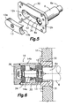
- Fig. 5 illustrates one of the mentioned supplementary parts 32 having the corresponding elongated hole 12 formed therein, the pivot shaft 6 with one end 6a inserted inside said elongated hole 12 and one of said retaining parts 13 arranged to be inserted inside the elongated hole 12.
- the corresponding needle bearing 31 is mounted on the end 6a of the pivot shaft 6.
- the other supplementary part 32 and the other retaining part 13 are identical to those shown in Fig. 5 and descriptions thereof are omitted.
- the elongated hole has two parallel, facing, curved inner walls, which are connected by two inner, rounded end walls 12a, 12b.
- the distance between said two parallel, curved inner walls is nominally equal to the outside diameter of the needle bearings 31 and the radius of said inner, rounded end walls 12a, 12b is nominally equal to the outside radius of the needle bearings 31.
- the retaining part 13 is adapted to retain the end 6a of the pivot shaft 6 against one of the end walls 12a, 12b of the elongated hole 12 (the second end wall 12b to the right of the elongated hole 12 in Fig. 5 ).
- the retaining part 13 comprises a first end 13a adapted to make contact with said first wall end 12a of the elongated hole 12 and a configuration 13b adapted to cooperate with the second end wall 12b of the elongated hole 12 in retaining the pivot shaft 6 in said fixed position.
- the mentioned configuration 13b of the retaining part 13 defines a curved wall with a radius is nominally equal to the outside radius of the needle bearing 31 and a centre aligned with the centre of the pivot shaft 6 when the same is in a fixed position against the second wall end 12b of the elongated hole 12.
- the ends 6a of the pivot shaft 6 are held in position and the configurations 13b of the retaining parts 13 act as part of the rolling tracks for the needle bearings 31, while the end walls 12b of the elongated holes 12 act as another part of the rolling tracks for the needle bearings 31 in order to guide the pivoting of the active arm 4 about the pivot shaft 6, during closing and opening movements for welding as described above.
- the ends 6a of the pivot shaft 6 can be freely moved along the elongated holes 12 permitting pivoting movements of the active arm 4 about the first articulation pin 7a during the movements between the previously described open and extra-open positions.
- the welding gun In order to automatically perform the movements of the retaining parts 13, the welding gun includes two retention actuators 14, exteriorly shown in Fig. 4 .
- each of the mentioned retention actuators 14 has a casing 14b that is fixed with respect to a corresponding one of the first plates 11 of the passive arm 2.
- the retention actuators 14 are expressly adapted for a maximum compactness and are fixed to the corresponding supplementary parts 32 which, in turn, are secured to the corresponding first plates 11 of the passive arm 2.
- the casing 14b of each retention actuator 14 defines a chamber containing a piston 34 and an extendible rod 14a is connected at one end to said piston 34 and at the other to the corresponding retaining part 13.
- the retention actuators 14 can comprise any other type of commercially available pneumatic cylinder or electric motors, with the sole condition that they can carry out the mentioned movements of the retaining parts 13.
- One movement of the retention actuators 14 to extend the rod 14a produces the insertion of the retaining parts 13 into the respective elongated holes 12.
- One movement of the retention actuators 14 in the opposite direction extracts the retaining parts 13 from the elongated holes 12.
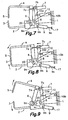
- the welding gun of Figs. 7 to 9 comprises, as for the exemplary embodiment previously described with respect to Figs. 1 to 3 , a base support 1, a passive arm 2, and an active arm 4 to which a pivot shaft 6 is connected which, in turn is coupled to rotation means 20 associated with the passive arm 2.
- the passive arm 2 is here mounted to pivot about a second pivot shaft 8 with respect to the base support 1.
- the first linear actuator 7 has an extendible rod 7a connected to the active arm 4 by means of a first articulation pin 7a and a casing connected to the passive arm 2 by means of a second articulation shaft 7b.
- the second linear actuator 9 has an extendible rod 9a connected to the active arm 4 by means of a second articulation pin 9a and a casing connected to the passive arm 2 by means of a second articulation shaft 9b.
- the welding gun also comprises a third linear actuator 10 with an extendible rod connected to the passive arm 2 by a third articulation pin 10a and a casing connected to the base support 1 by means of a third articulation shaft 10b.
- the mentioned third linear actuator 10 can be operated to jointly pivot the passive 2 and active 4 arms about said second pivot shaft 8 without altering the relative position between the passive 2 and active 4 arms.
- the welding gun schematically illustrated in Figs. 7 to 9 is suitable for robotic operation. To this end, the base body 1 is coupled to a moving member of the robot (not shown) and the welding gun is connected to a control unit associated with said robot to execute an automatic welding gun handling program including positioning and welding operations.
- the welding gun is shown in Fig. 7 in a neutral open position, from which closing and opening movements for welding and extra-open movements for positioning can be performed.
- an action of the first linear actuator 7 to extend its rod 7a and an action of the third linear actuator 10 to retract its rod 10a produce pivoting of the passive and active arms 2, 4 about the second and first pivot shafts 8, 6 respectively, from the open position shown in Fig. 7 to the closed position, shown in Fig. 8 , to perform a welding operation.
- a subsequent action of the first and third linear actuators 7, 10 in respective opposite directions return the welding gun to the open position shown in Fig. 7 .
- an action of the second linear actuator 9 to extend its rod 9a and an action of the third linear actuator 10 to retract its rod 10a produce pivoting of the passive and active arms 2, 4 about the second pivot shaft 8 and the first articulation pin 7a respectively, with a movement of the first pivot shaft 6 along the guiding means 20, from the open position shown in Fig. 7 to the extra-open position shown in Fig. 9 to carry out a welding gun positioning operation overcoming obstacles existing between the base support 1 and the point where the electrodes 3, 5 are going to perform the welding operation.
- a subsequent action of the second and third linear actuators 9, 10 in respective opposite directions return the welding gun to the open position shown in Fig. 7 .
- a second linear actuator 9 is a double-rod type and comprises a second extendible rod 9c that projects from the cylinder head, i.e. the end of the casing opposite said extendible rod connected to the active arm 4 by said second articulation pin 9a. Both rods are mutually connected so that when the first one extends the second one retracts, and vice versa.
- a stop 17 is mounted on said second rod 9c, said stop 17 being associated with regulation means adapted to regulate and fix the position of said stop 17 long the second rod 9c, for example, using a nut and locknut arrangement (not shown), or any other device that would easily occur to an skilled in the art.
- the stop 17 can be fixed on the second rod 9c in such a position that, during an extra-open operation, the stop 17 makes contact with the cylinder head of cylinder 9 before the pivot shaft has reached the end of the guiding means 20 (for example, at the first end 12a of the elongated holes 12 in accordance with the exemplary embodiment shown in Fig. 5 ), thereby limiting and regulating the maximum angle permitted to the active arm 4 in said extra-open position.
- the regulation means described with respect to the welding gun adapted for robotic operation shown in Figs. 7 to 9 including a double-rod type second linear actuator 9 and a stop 17 associated with the second rod 9c are as well applicable to the welding gun adapted for manual operation described with respect to Figs. 1 to 3 .
- Another significant feature of the welding gun of the present invention is that it is prepared to be easily and simply adapted to the configuration of new pieces to be welded or to a change in application.
- distal portions 26, 29 of the passive and active arms 2, 4 are provided with ends located between the two parallel plates 11, 28 of the respective proximal portions and are fixed to the same by securing nut and bolt assemblies 27, 30 respectively.
- this adaptation is achieved by simply removing the securing nut and bolt assemblies 27, 30 in order to replace only the distal portions 26, 29 by other ones suitable for the new configuration or application and then reinstalling the securing nut and bolt assemblies 27, 30, apart from, naturally, acting on the electric and cooling fluid connections.
- the new distal portions 26, 29 include the respective electrodes 3, 5 suitable for the new configuration or application.
- the welding gun of the present invention provides a wide range of possible combinations of both parameters for adaptation to a variety of configurations or applications.
- a table is given below that lists various welding gun working depth dimensions provided by arms of various lengths, with the corresponding maximum gaps between electrodes reached between the maximum extra-open position and corresponding closing force between the electrodes for a welding gun such as that shown in Figs. 1 to 3 , with the first pneumatic cylinder constituting the first linear actuator 7 working at a pressure of 6 bar.
- the working depth dimensions correspond to the distance normal to the first electrode 3 between the first electrode 3 and the pivot shaft 6 with the welding gun in the open or closed position shown in Figs. 1 and 2 .
- the maximum gap between electrodes corresponds to the distance normal to the line that joins the tip of the first electrode 3 to the pivot shaft 6 between the tips of the first and second electrodes 3 and 5 when the welding gun is in the extra-open position shown in Fig. 3 .
- Table Relationships between working depth, maximum opening and closing force Working depth (mm) Maximum gap (mm) Approximate force (daN) 400 221.0 950 500 274.1 875 600 327.7 800 700 381.6 710 800 435.8 640 900 490.2 555 1000 544.7 480 1100 593.3 300 1200 654.0 210
Priority Applications (4)
| Application Number | Priority Date | Filing Date | Title |
|---|---|---|---|
| EP06380047A EP1834726B1 (en) | 2006-03-13 | 2006-03-13 | Electric resistance welding gun |
| DE602006002246T DE602006002246D1 (de) | 2006-03-13 | 2006-03-13 | Elektrische Widerstandsschweisszange |
| ES06380047T ES2313597T3 (es) | 2006-03-13 | 2006-03-13 | Pinza de soldadura por resitencia electrica. |
| AT06380047T ATE404315T1 (de) | 2006-03-13 | 2006-03-13 | Elektrische widerstandsschweisszange |
Applications Claiming Priority (1)
| Application Number | Priority Date | Filing Date | Title |
|---|---|---|---|
| EP06380047A EP1834726B1 (en) | 2006-03-13 | 2006-03-13 | Electric resistance welding gun |
Publications (2)
| Publication Number | Publication Date |
|---|---|
| EP1834726A1 EP1834726A1 (en) | 2007-09-19 |
| EP1834726B1 true EP1834726B1 (en) | 2008-08-13 |
Family
ID=36699178
Family Applications (1)
| Application Number | Title | Priority Date | Filing Date |
|---|---|---|---|
| EP06380047A Not-in-force EP1834726B1 (en) | 2006-03-13 | 2006-03-13 | Electric resistance welding gun |
Country Status (4)
| Country | Link |
|---|---|
| EP (1) | EP1834726B1 (es) |
| AT (1) | ATE404315T1 (es) |
| DE (1) | DE602006002246D1 (es) |
| ES (1) | ES2313597T3 (es) |
Families Citing this family (1)
| Publication number | Priority date | Publication date | Assignee | Title |
|---|---|---|---|---|
| US11484964B2 (en) * | 2019-06-06 | 2022-11-01 | Joran Olsson | Resistance multi purpose welder attachment |
Family Cites Families (4)
| Publication number | Priority date | Publication date | Assignee | Title |
|---|---|---|---|---|
| US4525618A (en) * | 1983-10-26 | 1985-06-25 | Beneteau Donald J | Resistance welding apparatus |
| US5063278A (en) * | 1988-06-22 | 1991-11-05 | Honda Giken Kogyo Kabushiki Kaisha | Method and apparatus for supplying electric power to resistance welding gun |
| US5111020A (en) * | 1991-05-02 | 1992-05-05 | Ariel Stiebel | Method and apparatus for controlling electrical resistance spot welding |
| ES1055232Y (es) * | 2003-06-30 | 2004-02-16 | Dauden Antonio Jordan | Pinzas de soldadura por resistencia electrica con control de cierre. |
-
2006
- 2006-03-13 ES ES06380047T patent/ES2313597T3/es active Active
- 2006-03-13 EP EP06380047A patent/EP1834726B1/en not_active Not-in-force
- 2006-03-13 DE DE602006002246T patent/DE602006002246D1/de active Active
- 2006-03-13 AT AT06380047T patent/ATE404315T1/de not_active IP Right Cessation
Also Published As
| Publication number | Publication date |
|---|---|
| DE602006002246D1 (de) | 2008-09-25 |
| ATE404315T1 (de) | 2008-08-15 |
| ES2313597T3 (es) | 2009-03-01 |
| EP1834726A1 (en) | 2007-09-19 |
Similar Documents
| Publication | Publication Date | Title |
|---|---|---|
| EP2452772B1 (en) | Resistance spot welder | |
| KR101212827B1 (ko) | 저항 스폿 용접기 | |
| CN109578663B (zh) | 密集安装阀门的操作装置 | |
| EP1472040B1 (de) | Antriebsvorrichtung für eine schweisszange | |
| JPS5815277B2 (ja) | 工業用ロボツト | |
| EP1834726B1 (en) | Electric resistance welding gun | |
| US10357929B2 (en) | Device and method for adjusting the height of a mold of a tire curing press, and tire curing press | |
| KR102422557B1 (ko) | 인가된 힘을 연결 요소에 적용하기 위한 장치 | |
| CN111216098A (zh) | 一种带夹爪的自动装配机器人装置 | |
| US20180281164A1 (en) | Extractor and extraction process of an injector stuck in the engine cylinder head of a motor vehicle | |
| EP3898024B1 (en) | Apparatus to manipulate products to be forged | |
| JP2007260772A (ja) | テ−ブル電極を利用する自動スポット溶接機 | |
| CN107262894A (zh) | 具有中断式中心轴的钢轨闪光焊机 | |
| JP2010222911A (ja) | 側方案内式案内軌条調節装置 | |
| CN207806864U (zh) | 具有中断式中心轴的钢轨闪光焊机 | |
| WO2021081695A1 (zh) | 一种正火机 | |
| WO2020178158A1 (de) | Antriebssystem | |
| US7952046B2 (en) | Resistance welding gun with independent actuators | |
| CN220659779U (zh) | 一种侧围总成预拼柔性抓手 | |
| WO2012011231A1 (ja) | ヘミング装置 | |
| CN220782017U (zh) | 一种钣金旋转铆钳 | |
| CN214944093U (zh) | 一种复合式排管机用扶持机械手钳头 | |
| JP2002011580A (ja) | 抵抗溶接機と電極アームの懐高さ調整方法 | |
| JP2021178381A (ja) | クランプ装置 | |
| CN109290689B (zh) | 一种焊接夹具及焊接设备 |
Legal Events
| Date | Code | Title | Description |
|---|---|---|---|
| PUAI | Public reference made under article 153(3) epc to a published international application that has entered the european phase |
Free format text: ORIGINAL CODE: 0009012 |
|
| AK | Designated contracting states |
Kind code of ref document: A1 Designated state(s): AT BE BG CH CY CZ DE DK EE ES FI FR GB GR HU IE IS IT LI LT LU LV MC NL PL PT RO SE SI SK TR |
|
| AX | Request for extension of the european patent |
Extension state: AL BA HR MK YU |
|
| 17P | Request for examination filed |
Effective date: 20080130 |
|
| GRAP | Despatch of communication of intention to grant a patent |
Free format text: ORIGINAL CODE: EPIDOSNIGR1 |
|
| AKX | Designation fees paid |
Designated state(s): AT BE BG CH CY CZ DE DK EE ES FI FR GB GR HU IE IS IT LI LT LU LV MC NL PL PT RO SE SI SK TR |
|
| GRAS | Grant fee paid |
Free format text: ORIGINAL CODE: EPIDOSNIGR3 |
|
| GRAA | (expected) grant |
Free format text: ORIGINAL CODE: 0009210 |
|
| AK | Designated contracting states |
Kind code of ref document: B1 Designated state(s): AT BE BG CH CY CZ DE DK EE ES FI FR GB GR HU IE IS IT LI LT LU LV MC NL PL PT RO SE SI SK TR |
|
| REG | Reference to a national code |
Ref country code: GB Ref legal event code: FG4D |
|
| REG | Reference to a national code |
Ref country code: CH Ref legal event code: EP |
|
| REG | Reference to a national code |
Ref country code: IE Ref legal event code: FG4D |
|
| REF | Corresponds to: |
Ref document number: 602006002246 Country of ref document: DE Date of ref document: 20080925 Kind code of ref document: P |
|
| PG25 | Lapsed in a contracting state [announced via postgrant information from national office to epo] |
Ref country code: NL Free format text: LAPSE BECAUSE OF FAILURE TO SUBMIT A TRANSLATION OF THE DESCRIPTION OR TO PAY THE FEE WITHIN THE PRESCRIBED TIME-LIMIT Effective date: 20080813 Ref country code: IS Free format text: LAPSE BECAUSE OF FAILURE TO SUBMIT A TRANSLATION OF THE DESCRIPTION OR TO PAY THE FEE WITHIN THE PRESCRIBED TIME-LIMIT Effective date: 20081213 Ref country code: LT Free format text: LAPSE BECAUSE OF FAILURE TO SUBMIT A TRANSLATION OF THE DESCRIPTION OR TO PAY THE FEE WITHIN THE PRESCRIBED TIME-LIMIT Effective date: 20080813 |
|
| PG25 | Lapsed in a contracting state [announced via postgrant information from national office to epo] |
Ref country code: AT Free format text: LAPSE BECAUSE OF FAILURE TO SUBMIT A TRANSLATION OF THE DESCRIPTION OR TO PAY THE FEE WITHIN THE PRESCRIBED TIME-LIMIT Effective date: 20080813 Ref country code: FI Free format text: LAPSE BECAUSE OF FAILURE TO SUBMIT A TRANSLATION OF THE DESCRIPTION OR TO PAY THE FEE WITHIN THE PRESCRIBED TIME-LIMIT Effective date: 20080813 Ref country code: LV Free format text: LAPSE BECAUSE OF FAILURE TO SUBMIT A TRANSLATION OF THE DESCRIPTION OR TO PAY THE FEE WITHIN THE PRESCRIBED TIME-LIMIT Effective date: 20080813 Ref country code: SI Free format text: LAPSE BECAUSE OF FAILURE TO SUBMIT A TRANSLATION OF THE DESCRIPTION OR TO PAY THE FEE WITHIN THE PRESCRIBED TIME-LIMIT Effective date: 20080813 |
|
| REG | Reference to a national code |
Ref country code: ES Ref legal event code: FG2A Ref document number: 2313597 Country of ref document: ES Kind code of ref document: T3 |
|
| PG25 | Lapsed in a contracting state [announced via postgrant information from national office to epo] |
Ref country code: BE Free format text: LAPSE BECAUSE OF FAILURE TO SUBMIT A TRANSLATION OF THE DESCRIPTION OR TO PAY THE FEE WITHIN THE PRESCRIBED TIME-LIMIT Effective date: 20080813 |
|
| REG | Reference to a national code |
Ref country code: GB Ref legal event code: S117 Free format text: REQUEST FILED; REQUEST FOR CORRECTION UNDER SECTION 117 FILED ON 12 JANUARY 2009 |
|
| PG25 | Lapsed in a contracting state [announced via postgrant information from national office to epo] |
Ref country code: DK Free format text: LAPSE BECAUSE OF FAILURE TO SUBMIT A TRANSLATION OF THE DESCRIPTION OR TO PAY THE FEE WITHIN THE PRESCRIBED TIME-LIMIT Effective date: 20080813 Ref country code: BG Free format text: LAPSE BECAUSE OF FAILURE TO SUBMIT A TRANSLATION OF THE DESCRIPTION OR TO PAY THE FEE WITHIN THE PRESCRIBED TIME-LIMIT Effective date: 20081113 |
|
| PG25 | Lapsed in a contracting state [announced via postgrant information from national office to epo] |
Ref country code: RO Free format text: LAPSE BECAUSE OF FAILURE TO SUBMIT A TRANSLATION OF THE DESCRIPTION OR TO PAY THE FEE WITHIN THE PRESCRIBED TIME-LIMIT Effective date: 20080813 Ref country code: PT Free format text: LAPSE BECAUSE OF FAILURE TO SUBMIT A TRANSLATION OF THE DESCRIPTION OR TO PAY THE FEE WITHIN THE PRESCRIBED TIME-LIMIT Effective date: 20090113 Ref country code: CZ Free format text: LAPSE BECAUSE OF FAILURE TO SUBMIT A TRANSLATION OF THE DESCRIPTION OR TO PAY THE FEE WITHIN THE PRESCRIBED TIME-LIMIT Effective date: 20080813 Ref country code: SK Free format text: LAPSE BECAUSE OF FAILURE TO SUBMIT A TRANSLATION OF THE DESCRIPTION OR TO PAY THE FEE WITHIN THE PRESCRIBED TIME-LIMIT Effective date: 20080813 |
|
| PLBE | No opposition filed within time limit |
Free format text: ORIGINAL CODE: 0009261 |
|
| STAA | Information on the status of an ep patent application or granted ep patent |
Free format text: STATUS: NO OPPOSITION FILED WITHIN TIME LIMIT |
|
| 26N | No opposition filed |
Effective date: 20090514 |
|
| PG25 | Lapsed in a contracting state [announced via postgrant information from national office to epo] |
Ref country code: EE Free format text: LAPSE BECAUSE OF FAILURE TO SUBMIT A TRANSLATION OF THE DESCRIPTION OR TO PAY THE FEE WITHIN THE PRESCRIBED TIME-LIMIT Effective date: 20080813 |
|
| PG25 | Lapsed in a contracting state [announced via postgrant information from national office to epo] |
Ref country code: MC Free format text: LAPSE BECAUSE OF NON-PAYMENT OF DUE FEES Effective date: 20090331 |
|
| REG | Reference to a national code |
Ref country code: GB Ref legal event code: S117 Free format text: CORRECTIONS ALLOWED; REQUEST FOR CORRECTION UNDER SECTION 117 FILED ON 12 JANUARY 2009 ALLOWED ON 9 NOVEMBER 2009 |
|
| REG | Reference to a national code |
Ref country code: IE Ref legal event code: MM4A |
|
| PG25 | Lapsed in a contracting state [announced via postgrant information from national office to epo] |
Ref country code: IE Free format text: LAPSE BECAUSE OF NON-PAYMENT OF DUE FEES Effective date: 20090313 Ref country code: SE Free format text: LAPSE BECAUSE OF FAILURE TO SUBMIT A TRANSLATION OF THE DESCRIPTION OR TO PAY THE FEE WITHIN THE PRESCRIBED TIME-LIMIT Effective date: 20081113 |
|
| PG25 | Lapsed in a contracting state [announced via postgrant information from national office to epo] |
Ref country code: PL Free format text: LAPSE BECAUSE OF FAILURE TO SUBMIT A TRANSLATION OF THE DESCRIPTION OR TO PAY THE FEE WITHIN THE PRESCRIBED TIME-LIMIT Effective date: 20080813 |
|
| PG25 | Lapsed in a contracting state [announced via postgrant information from national office to epo] |
Ref country code: GR Free format text: LAPSE BECAUSE OF FAILURE TO SUBMIT A TRANSLATION OF THE DESCRIPTION OR TO PAY THE FEE WITHIN THE PRESCRIBED TIME-LIMIT Effective date: 20081114 |
|
| REG | Reference to a national code |
Ref country code: CH Ref legal event code: PL |
|
| PG25 | Lapsed in a contracting state [announced via postgrant information from national office to epo] |
Ref country code: LI Free format text: LAPSE BECAUSE OF NON-PAYMENT OF DUE FEES Effective date: 20100331 Ref country code: CH Free format text: LAPSE BECAUSE OF NON-PAYMENT OF DUE FEES Effective date: 20100331 |
|
| PG25 | Lapsed in a contracting state [announced via postgrant information from national office to epo] |
Ref country code: LU Free format text: LAPSE BECAUSE OF NON-PAYMENT OF DUE FEES Effective date: 20090313 |
|
| PG25 | Lapsed in a contracting state [announced via postgrant information from national office to epo] |
Ref country code: HU Free format text: LAPSE BECAUSE OF FAILURE TO SUBMIT A TRANSLATION OF THE DESCRIPTION OR TO PAY THE FEE WITHIN THE PRESCRIBED TIME-LIMIT Effective date: 20090214 |
|
| PG25 | Lapsed in a contracting state [announced via postgrant information from national office to epo] |
Ref country code: TR Free format text: LAPSE BECAUSE OF FAILURE TO SUBMIT A TRANSLATION OF THE DESCRIPTION OR TO PAY THE FEE WITHIN THE PRESCRIBED TIME-LIMIT Effective date: 20080813 |
|
| PG25 | Lapsed in a contracting state [announced via postgrant information from national office to epo] |
Ref country code: CY Free format text: LAPSE BECAUSE OF FAILURE TO SUBMIT A TRANSLATION OF THE DESCRIPTION OR TO PAY THE FEE WITHIN THE PRESCRIBED TIME-LIMIT Effective date: 20080813 |
|
| PGFP | Annual fee paid to national office [announced via postgrant information from national office to epo] |
Ref country code: ES Payment date: 20140319 Year of fee payment: 9 Ref country code: IT Payment date: 20140321 Year of fee payment: 9 |
|
| PGFP | Annual fee paid to national office [announced via postgrant information from national office to epo] |
Ref country code: GB Payment date: 20140324 Year of fee payment: 9 |
|
| PGFP | Annual fee paid to national office [announced via postgrant information from national office to epo] |
Ref country code: DE Payment date: 20140527 Year of fee payment: 9 Ref country code: FR Payment date: 20140327 Year of fee payment: 9 |
|
| REG | Reference to a national code |
Ref country code: DE Ref legal event code: R119 Ref document number: 602006002246 Country of ref document: DE |
|
| GBPC | Gb: european patent ceased through non-payment of renewal fee |
Effective date: 20150313 |
|
| PG25 | Lapsed in a contracting state [announced via postgrant information from national office to epo] |
Ref country code: IT Free format text: LAPSE BECAUSE OF NON-PAYMENT OF DUE FEES Effective date: 20150313 |
|
| REG | Reference to a national code |
Ref country code: FR Ref legal event code: ST Effective date: 20151130 |
|
| PG25 | Lapsed in a contracting state [announced via postgrant information from national office to epo] |
Ref country code: GB Free format text: LAPSE BECAUSE OF NON-PAYMENT OF DUE FEES Effective date: 20150313 Ref country code: DE Free format text: LAPSE BECAUSE OF NON-PAYMENT OF DUE FEES Effective date: 20151001 |
|
| PG25 | Lapsed in a contracting state [announced via postgrant information from national office to epo] |
Ref country code: FR Free format text: LAPSE BECAUSE OF NON-PAYMENT OF DUE FEES Effective date: 20150331 |
|
| REG | Reference to a national code |
Ref country code: ES Ref legal event code: FD2A Effective date: 20160426 |
|
| PG25 | Lapsed in a contracting state [announced via postgrant information from national office to epo] |
Ref country code: ES Free format text: LAPSE BECAUSE OF NON-PAYMENT OF DUE FEES Effective date: 20150314 |