EP1834701B1 - Actuator for a receptacle having a pressurized content and method for spraying a pressurized content - Google Patents
Actuator for a receptacle having a pressurized content and method for spraying a pressurized content Download PDFInfo
- Publication number
- EP1834701B1 EP1834701B1 EP06075598A EP06075598A EP1834701B1 EP 1834701 B1 EP1834701 B1 EP 1834701B1 EP 06075598 A EP06075598 A EP 06075598A EP 06075598 A EP06075598 A EP 06075598A EP 1834701 B1 EP1834701 B1 EP 1834701B1
- Authority
- EP
- European Patent Office
- Prior art keywords
- actuator
- orifice
- volume chamber
- inlet
- piston
- Prior art date
- Legal status (The legal status is an assumption and is not a legal conclusion. Google has not performed a legal analysis and makes no representation as to the accuracy of the status listed.)
- Active
Links
- 238000005507 spraying Methods 0.000 title claims abstract description 38
- 238000000034 method Methods 0.000 title description 4
- 230000009467 reduction Effects 0.000 claims description 10
- 230000007704 transition Effects 0.000 claims description 3
- 230000008878 coupling Effects 0.000 abstract description 3
- 238000010168 coupling process Methods 0.000 abstract description 3
- 238000005859 coupling reaction Methods 0.000 abstract description 3
- 239000012530 fluid Substances 0.000 description 25
- 239000000126 substance Substances 0.000 description 11
- 239000007788 liquid Substances 0.000 description 10
- IJGRMHOSHXDMSA-UHFFFAOYSA-N Atomic nitrogen Chemical compound N#N IJGRMHOSHXDMSA-UHFFFAOYSA-N 0.000 description 8
- 239000003380 propellant Substances 0.000 description 8
- 239000007789 gas Substances 0.000 description 6
- 239000000203 mixture Substances 0.000 description 6
- 239000000047 product Substances 0.000 description 5
- 229910052757 nitrogen Inorganic materials 0.000 description 4
- 239000000443 aerosol Substances 0.000 description 3
- 238000001746 injection moulding Methods 0.000 description 3
- 238000004519 manufacturing process Methods 0.000 description 3
- 238000007789 sealing Methods 0.000 description 3
- 238000011144 upstream manufacturing Methods 0.000 description 3
- 239000002360 explosive Substances 0.000 description 2
- 239000011261 inert gas Substances 0.000 description 2
- 239000000463 material Substances 0.000 description 2
- 238000012986 modification Methods 0.000 description 2
- 230000004048 modification Effects 0.000 description 2
- 230000009471 action Effects 0.000 description 1
- 230000001154 acute effect Effects 0.000 description 1
- 238000007792 addition Methods 0.000 description 1
- 239000003570 air Substances 0.000 description 1
- 238000006243 chemical reaction Methods 0.000 description 1
- 238000010276 construction Methods 0.000 description 1
- 239000006071 cream Substances 0.000 description 1
- 238000012217 deletion Methods 0.000 description 1
- 230000037430 deletion Effects 0.000 description 1
- 230000001419 dependent effect Effects 0.000 description 1
- 230000003467 diminishing effect Effects 0.000 description 1
- 239000003344 environmental pollutant Substances 0.000 description 1
- 238000002474 experimental method Methods 0.000 description 1
- 229920002457 flexible plastic Polymers 0.000 description 1
- 239000008266 hair spray Substances 0.000 description 1
- 231100001261 hazardous Toxicity 0.000 description 1
- 230000006872 improvement Effects 0.000 description 1
- 230000000977 initiatory effect Effects 0.000 description 1
- 239000004922 lacquer Substances 0.000 description 1
- 239000012263 liquid product Substances 0.000 description 1
- 231100000252 nontoxic Toxicity 0.000 description 1
- 230000003000 nontoxic effect Effects 0.000 description 1
- 231100000719 pollutant Toxicity 0.000 description 1
- 238000003825 pressing Methods 0.000 description 1
- 239000000243 solution Substances 0.000 description 1
- 239000007921 spray Substances 0.000 description 1
- 238000006467 substitution reaction Methods 0.000 description 1
Images

Classifications
-
- B—PERFORMING OPERATIONS; TRANSPORTING
- B05—SPRAYING OR ATOMISING IN GENERAL; APPLYING FLUENT MATERIALS TO SURFACES, IN GENERAL
- B05B—SPRAYING APPARATUS; ATOMISING APPARATUS; NOZZLES
- B05B11/00—Single-unit hand-held apparatus in which flow of contents is produced by the muscular force of the operator at the moment of use
- B05B11/01—Single-unit hand-held apparatus in which flow of contents is produced by the muscular force of the operator at the moment of use characterised by the means producing the flow
- B05B11/10—Pump arrangements for transferring the contents from the container to a pump chamber by a sucking effect and forcing the contents out through the dispensing nozzle
- B05B11/1042—Components or details
- B05B11/1073—Springs
- B05B11/1077—Springs characterised by a particular shape or material
-
- B—PERFORMING OPERATIONS; TRANSPORTING
- B05—SPRAYING OR ATOMISING IN GENERAL; APPLYING FLUENT MATERIALS TO SURFACES, IN GENERAL
- B05B—SPRAYING APPARATUS; ATOMISING APPARATUS; NOZZLES
- B05B11/00—Single-unit hand-held apparatus in which flow of contents is produced by the muscular force of the operator at the moment of use
- B05B11/0005—Components or details
- B05B11/0062—Outlet valves actuated by the pressure of the fluid to be sprayed
- B05B11/0064—Lift valves
- B05B11/0067—Lift valves having a valve seat located downstream the valve element
-
- B—PERFORMING OPERATIONS; TRANSPORTING
- B65—CONVEYING; PACKING; STORING; HANDLING THIN OR FILAMENTARY MATERIAL
- B65D—CONTAINERS FOR STORAGE OR TRANSPORT OF ARTICLES OR MATERIALS, e.g. BAGS, BARRELS, BOTTLES, BOXES, CANS, CARTONS, CRATES, DRUMS, JARS, TANKS, HOPPERS, FORWARDING CONTAINERS; ACCESSORIES, CLOSURES, OR FITTINGS THEREFOR; PACKAGING ELEMENTS; PACKAGES
- B65D83/00—Containers or packages with special means for dispensing contents
- B65D83/14—Containers or packages with special means for dispensing contents for delivery of liquid or semi-liquid contents by internal gaseous pressure, i.e. aerosol containers comprising propellant for a product delivered by a propellant
- B65D83/44—Valves specially adapted therefor; Regulating devices
-
- B—PERFORMING OPERATIONS; TRANSPORTING
- B65—CONVEYING; PACKING; STORING; HANDLING THIN OR FILAMENTARY MATERIAL
- B65D—CONTAINERS FOR STORAGE OR TRANSPORT OF ARTICLES OR MATERIALS, e.g. BAGS, BARRELS, BOTTLES, BOXES, CANS, CARTONS, CRATES, DRUMS, JARS, TANKS, HOPPERS, FORWARDING CONTAINERS; ACCESSORIES, CLOSURES, OR FITTINGS THEREFOR; PACKAGING ELEMENTS; PACKAGES
- B65D83/00—Containers or packages with special means for dispensing contents
- B65D83/14—Containers or packages with special means for dispensing contents for delivery of liquid or semi-liquid contents by internal gaseous pressure, i.e. aerosol containers comprising propellant for a product delivered by a propellant
- B65D83/75—Aerosol containers not provided for in groups B65D83/16 - B65D83/74
- B65D83/753—Aerosol containers not provided for in groups B65D83/16 - B65D83/74 characterised by details or accessories associated with outlets
- B65D83/7535—Outlet valves opened by the product to be delivered
-
- B—PERFORMING OPERATIONS; TRANSPORTING
- B05—SPRAYING OR ATOMISING IN GENERAL; APPLYING FLUENT MATERIALS TO SURFACES, IN GENERAL
- B05B—SPRAYING APPARATUS; ATOMISING APPARATUS; NOZZLES
- B05B11/00—Single-unit hand-held apparatus in which flow of contents is produced by the muscular force of the operator at the moment of use
- B05B11/01—Single-unit hand-held apparatus in which flow of contents is produced by the muscular force of the operator at the moment of use characterised by the means producing the flow
- B05B11/10—Pump arrangements for transferring the contents from the container to a pump chamber by a sucking effect and forcing the contents out through the dispensing nozzle
- B05B11/1001—Piston pumps
- B05B11/1016—Piston pumps the outlet valve having a valve seat located downstream a movable valve element controlled by a pressure actuated controlling element
Definitions
- the invention relates to an actuator for a dispenser device for spraying content of a receptacle that is pressurized or of a receptacle that has a pump, comprising a channel connectable to a receptacle outlet on one side of the actuator for receiving the pressurized content of the receptacle, said actuator having an orifice for spraying the contents on another side of the actuator connectable with the channel according to the preamble of claim 1.
- the invention also relates to an assembly of an actuator and receptacle.
- an aerosol can a vessel or a bag-in-box, be filled with a fluid to be sprayed.
- This fluid may be a gas as well as a liquid.
- a fluid is a liquid, this may also be a viscous liquid.
- a fluid' is also understood to mean a cream, paste, gel, powdery substance and possible combinations thereof.
- aerosol cans for spraying an atomized liquid, hair products, products suitable for consumption, etc.
- the receptacle contains the fluid to be sprayed mixed with a pressurized, compressible gas, preferably air or an inert propellant, such as nitrogen.
- a mixed substance is to be understood as at least two substances in one container space.
- the invention relates specifically to actuators for use on receptacles having a propellant such as air or inert gasses, as well as CO 2 , N X O, etc. filling mixed with a fluid to be sprayed.
- a propellant such as air or inert gasses, as well as CO 2 , N X O, etc. filling mixed with a fluid to be sprayed.
- the orifice of the actuator is adapted for spraying the mix of propellant and fluid.
- a channel in the actuator is connected to the orifice for creating a flow of contents from the outlet of the receptacle to the orifice.
- US 5,158,215 discloses an automatic lift valve for container containing a pressurized creamy or liquid product according to the preamble of claim 1 .
- the valve comprises a cylindrical chamber 2 in which a piston is cooperating with a spring for closing/opening the lift valve.
- a second valve 18 regulates the entry of the pressurized product into the chamber 2.
- a device for dispensing and spraying the contents of a receptacle that is pressurized or has a pump.
- the actuator is connected as dispensing head to the outlet of the receptacle.
- the actuator has a switch connected to a shutter which is mounted slidably in the actuator. The shutter closes the orifice.
- An actuator is coupled directly with the shutter for opening the orifice, resulting in spraying the contents flowing through the actuator.
- the object of the invention according to a first aspect is to provide a solution to the clogging of the sprayed substance.
- the invention also provides an actuator having an improved spraying pattern, in particular a spraying pattern indifferent of the filling or state of the receptacle. This includes known problems, such as spitting.
- the actuator is to be used with non-pollutant, e.g. air or nitrogen, propellants.
- the actuator comprises a volume chamber.
- the volume chamber can be part of the channel in the actuator.
- the contents of the receptacle can be collected.
- the orifice forms an outlet of the volume chamber.
- the volume chamber in the channel is positioned directly upstream from the orifice. If the contents in the volume chamber is allowed to flow out, it will be sprayed from the orifice.
- the orifice can be an interchangeable part of the actuator.
- the orifice has a valve for opening and closing the orifice or outlet of the volume chamber. This allows for a build-up of pressure in the volume chamber.
- the valve is biased by biasing means in the closed position of the valve, preventing the flow of substance through the channel.
- the valve is preferably coupled with a pressure sensor element for opening the valve upon reaching a threshold pressure in the volume chamber. This allows for a build-up of pressure in the chamber directly stream upwards from the orifice. Only after reaching a threshold value, the orifice is opened for spraying the contents. This retardation prevents a slow start of the spraying of the contents, when a user wishes to start spraying.
- the pressure at the orifice jumps directly to a desired over pressure corresponding to the over pressure in the chamber.
- the biasing means for closing the orifice are set a predetermined force or corresponding threshold pressure.
- the threshold pressure corresponds e.g. to a 0,5 - 20 Ato, preferably 1 - 12 Ato. If this pressure is build up in the chamber, the valve will be released.
- the orifice/actuator has a closed state and an opened state.
- the spraying can be initiated by the user pushing the actuator, resulting in the opening of the outlet of the receptacle.
- the actuator itself doesn't necessary have means to initiate or stop the flow of substance from the receptacle.
- the contents of the receptacle flow into the inlet of the actuator through the channel and is collected in the chamber.
- a pressure builds up. The pressure build up is sensed and from reaching the threshold value, the valve closing the orifice is opened, that orifice also being the outlet of the chamber.
- the pressure sensor element can be an electrical instrument coupled with a control for opening the valve.
- the pressure element can also be coupled with the biasing means for closing the valve, releasing the bias if a threshold pressure is reached.
- the volume chamber is an expandable volume chamber.
- the volume can be expanded in that at least one wall of the volume chamber is moveably mounted in the actuator.
- the volume chamber has at least one flexible wall, that can be elastically deformed. This also allows the volume chamber to have a small volume in the unexpanded state preventing clogging of leftover spraying contents.
- the volume of the chamber from inlet to outlet is preferably less than 5 mm 3 , advantageous less than 3 mm 3 .
- the pressure sensor element coupled with the expandable volume chamber. This allows the pressure sensor element to sense the expansion.
- the expansion corresponds to a pressure build-up in the volume chamber, and thus reaching a certain amount of expansion corresponds to reaching the threshold pressure for opening and closing the valve.
- An arm could be coupled with the pressure sensor, for sensing a predetermined amount of expansion, initiating the opening of the valve.
- the pressure sensor element has a surface, and the surface forms a moveable wall of the expandable volume chamber. If the wall is moved over a certain amount, e.g. overcoming a certain biasing force on said wall/surface, this indicates reaching a threshold pressure in the volume chamber.
- valve is adapted to essentially directly open the orifice completely. This could be a fast shutter. This allows the build-up pressure in the chamber to be immediately released through the orifice if opened.
- the biasing means could also be coupled with the moveable wall of the expandable chamber for biasing said wall in an unexpanded position of the chamber. The volume chamber is then biased in the unexpanded position.
- the valve comprises a piston having a piston body that is mounted moveable in the actuator, wherein the piston is received in and coupled with the actuator.
- the piston extends in the orifice and blocks the orifice in the closed/biased position. In the idle or standly position/state, the unexpanded chamber has a considerable smaller volume than prior art.
- the biasing means in a further embodiment are adapted for biasing the piston in a position closing the orifice.
- the biasing means can comprise spring means e.g. a leaf spring.
- the spring can be attached to the actuator, received in the actuator.
- the biasing means could be a gas chamber having a certain pressure.
- the piston forms e.g. the moveable wall of the expansion chamber. If the pressure build up in the chamber reaches a threshold value, overcoming the force exerted on the piston by the biasing means, the piston body moves.
- the piston has a pin extending from the piston body forming the valve for closing the orifice, resulting in the direct movement of the piston tip and opening the orifice if the threshold pressure value is reached.
- the piston body has a surface that forms the volume chamber wall, said surface extending preferably freely into the volume chamber in the closed state and the piston being moveable preferably acute to said surface.
- the surface dimensions and the force exerted by the biasing means correspond with the threshold value that should be reached to open the orifice.
- the actuator comprise guiding means for guiding the pin onto/into the orifice. This ascertains the movement of the pin back to the closed state if the pressure in the chamber drops under the threshold value.
- an actuator comprising inlet reduction means for reducing the size of an inlet to the channel and preferably to the volume chamber.
- the inlet closing means preferably reduce the inlet to the channel/chamber in an opened state of the orifice.
- the reduction of the inlet will lead to the decrease of pressure in the volume chamber. This reduces the pressure in the volume chamber under the pressure of the receptacle. This lowering and in turn controlling of the pressure in the actuator leads to better spraying patterns.
- the reduction of the inlet also stabilizes the pressure of the entire assembly of actuator and receptacle as known from EP 1 200 322 , which is included by reference.
- the pressure sensor element is coupled to the inlet reduction means for reducing the inlet.
- the size of the inlet is reduced.
- the reduction can be coupled with the same or a different threshold pressure in the volume chamber.
- the actuator comprises inlet enlargement means for enlarging the size of an inlet to the volume chamber in an closed state of the orifice, preferably in a transition from the opened state to the closed state.
- These enlargement means can be coupled to the biasing means.
- the pressure sensor element is coupled to the inlet enlargement means for enlarging the inlet size upon reaching a threshold pressure in the volume chamber.
- inlet to the volume chamber in the channel between the piston body and an interior, preferably a circular interior, wall of the actuator. This allows the use of the piston body for enlarging or reducing the inlet surface area in use during a transition from the closed state to the opened state and back.
- a seal such as a flat seal or O-ring is mounted on the piston and the seal, preferably the O-ring is adapted to reduce the size of the inlet of the volume chamber in the opened state.
- the O-ring is preferably mounted on the piston body.
- the piston body is preferably circular.
- the piston body with O-ring extends in the volume chamber. If a pressure is exerted on the piston the piston moves out of the volume chamber and the O-ring reduces the size of the inlet.
- the movement of the piston and O-ring is limited so that the O-ring does not fully block the inlet.
- the orifice cross sectional surface area is more than five time smaller than the volume chambers inlet cross sectional surface area. This allows the actuator to control in a limited fashion the pressure release from the receptacle.
- steps the pressure in the receptacle is reduced. In a first step the pressure is reduced to a pressure close to the threshold pressure in the volume chamber. The small orifice allows another pressure drop from the volume chamber pressure to the outside pressure. These pressure steps allow a better and more constant spraying pattern independent of the amount of the pressure in the receptacle.
- the actuator comprises at least an actuator hood, a first part receivable in the actuator hood having the orifice and the channel's inlet, a second part receivable in the first part for forming the channel from the inlet to the orifice and the piston receivable in the second part.
- These parts can be produced using injection moulding. Subsequent parts are received in the interior of the respective covers.
- the actuator hood comprises the orifice and channel inlet.
- the actuator can comprise a third part received in the second part for locking a spring that engages on the piston body biasing the piston for closing the orifice.
- the spring can engage on the flange of the piston body, preferably a circular surrounding flange extending outwardly from the piston body, while the spring is formed by helical spring surrounding the piston body.
- the invention also relates to an assembly of a pressurized receptacle and actuator comprising an actuator connected with the outlet of the receptacle.
- the receptacle can contain a pressurized content or has a pump for creating a pressure.
- the receptacle outlet can be opened.
- a flow of pressurized content preferably mixed with a fluid such a air or nitrogen or another suitable non-toxic propellant.
- the receptacle outlet is coupled with the actuator inlet to a channel through the actuator. The channel connects the actuator inlet with an orifice for spraying the content mixture.
- the invention also relates to a method for spraying contents of a receptacle comprising, providing a receptacle having contents that is pressurized or of a receptacle having a pump, flowing the pressurized contents into a volume chamber, building up of pressure in the volume chamber, opening an outlet of the volume chamber formed by an orifice for spraying the contents after reaching a threshold pressure in the volume chamber. This allows the spraying to be released at or near the threshold pressure, ensuring a better spraying pattern and resulting in less clogging of the contents on the actuator for spraying.
- the volume chamber is expanded by the flow of contents into the volume chamber.
- a wall of the volume chamber moves to expand the volume chamber.
- the wall and/or volume chamber is biased to the unexpanded state.
- the moving wall of the volume chamber couples the expansion to the opening of the orifice.
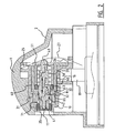
- Figure 1 shows the elements of an actuator according to a first embodiment.
- the actuator comprises an actuator hood 1 adapted to be fitted on top of a receptacle for spraying a substance.
- the actuator hood 1 comprises a press area 2 that the user can press in order to activate an assembly of actuator and receptacle for spraying or atomizing a substance.
- the actuator hood 1 is produced using an injection moulding technique.
- the hood 1 comprises an opening 3, wherein the orifice for spraying the substance can be received.
- the hood or cap 1 can be mounted on top of a receptacle and comprises a snap-on or clamping circular area 4 for clamping on the top part of a similar circular receptacle.
- a clamping flange 5 is formed on the inner side of the area 4.
- Other cross sections for hood 1 and receptacle are possible. The skilled person will be able to adapt the actuator to a corresponding receptacle.
- the actuator hood 1 is made of a flexible plastic. Other materials could be used.
- the hood 1 is primarily hollow in order to receive other parts of the actuator.
- a first part 10 has outside walls corresponding to the interior wall of hood 1 to be received in the interior of hood 1.
- First part 10 comprises the orifice 11 formed by a small opening in part 13.
- Part 13 could be an interchangeable part in order to differentiate the cross section of the orifice during manufacturing. By using a separate part 13 it is possible to mass produce first 10 and still obtain different orifices 11. Part 13 is locked into the opening 14 of first part 13.
- Part 13 has of general circular section.
- First part 10 is shown in cross section, as are the other elements in Figure 1 .
- an opening 16 connects the interior space 17 of first part 10 with the inlet space 18.
- Inlet space 18 comprises a space wherein the outlet 19 of a receptacle can be received in.
- the cross section of space 18 corresponds with the outlet cross section 19.
- the outlet 19 comprises a push button known per se, located on top of an aerosol can.
- the outlet 19 can comprises a shut-off valve for opening and closing the outlet. The shut-off valve is opened when, in the assembled state, a user presses the actuator down or sidewards on press area 2 of the actuator hood 1.
- the receptacle or package is not shown in Figure 1 is partially filled with a fluid possibly a liquid.
- the fluid is the product to be dispensed.
- the inner space of the receptacle can be filled with for example 85% liquid.
- an inert gas is present such as for example nitrogen.
- the outlet 19 dispenses the liquid/gas mixture from the top according to arrow 20.
- the mixture will be received in the first part 10 in the conduit 21 formed on top of space 18. From there the mixture will flow to the inlet opening 16.
- first part 10 comprises two receiving spaces 25,26 formed on the top and bottom end of the first part.
- the receiving spaces are adapted to hold a leaf spring 27 as will be described in more detail in the following.
- Second part 30 can be manufactured using injection moulding, but also other techniques can be used.
- the second part 30 is designed primarily as a guiding means for the piston 40.
- the second part, together with the first part form the volume chamber of the invention.
- Second part 30 has a conduit 32 leading from the outer side to the interior space 33.
- the second part 30 has a outside ridge 31 to engage and seal on the interior wall of the first part 10.
- the second part 30 has means for guiding the piston tip 34.
- the means comprise an opening 35 wherein the piston tip 41 can be received.
- the opening 35 comprises a tunnel directed at the orifice 11 is the assembled state.
- the piston 40 is received in the inner space 37 and space 33 of the second part 30.
- the piston tip 41 extends into the space 33 and into the opening 35.
- the piston comprises two O-rings 42,43 both having preferably a circular cross section.
- the piston can be completely cylindrical.
- the seal here O-ring 42 is received in the circular groove 44 on the piston body.
- the piston pin 41 extends beyond the groove 44.
- O-ring 43 is placed and clamps around piston 40 on the side 47. O-ring 43 will act as a seal sealing space 33 from space 37 if the piston 40 is received in the second part 30. The O-ring 43 is received in the area 36 in second part 30.
- a helical spring 50 and a closing body 51 can be received space 37 enclosing the piston 40 in the interior space of part 30.
- Closing body 51 has a ridge 52 that can be received in groove 38 in part 30 providing a snap connection locking the closing body 51 in the interior of second part 30.
- the spring 50 surrounds the body of piston 40 biasing the piston in the direction of arrow 55 towards the orifice 11. Spring 50 engages on edge 48 of the piston.
- the piston end part 49 extends through the opening 54 of the closing body 51.
- the spring leaf 27 will engage on this end and will also form a biasing means forcing the piston in the direction of arrow 55.
- the spring 50 is a biasing means for closing the valve.
- the leaf spring 27 additionally biases the valve in the closed position.
- spring 50 biases the volume chambers in the non-expanded state.
- Leaf spring 27 is bended if a user exerts force on area 2, allowing movement of the piston according to arrow 55. If the user stops pushing the actuator 1, the spring leaf immediately closes the valve pushing the piston on the orifice.
- the spring 50 holds the closed state directly, but temporally after actuation.
- the force exerted by leaf spring 27 corresponds to multiple time the force needed to close the orifice or to remove the piston to the non-expanded state of the volume chamber 71.
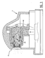
- Figure 2 shows the actuator hood in the assembled state, placed on the outlet 19 of a receptacle. Now the channel or conduit formed in the actuator will be discussed.
- the content can in this embodiment only flow through the opening 60 surround the second part 30 and surrounded by the interior wall of the first part 10.
- the opening 60 is connected with opening 32 in the second part 30. From the opening 32 the flow can continue through the inlet 64 between the piston 40 and second part 30.
- the inlet 64 is formed by side 63 of the piston and ridge 65 extending inwards from the second part 30.
- the inlet 64 has extends circularly around the piston body 40 and between the ridge 65. Even if the piston is moved a fraction sideways according to arrow 70, the inlet 64 maintains its original size.
- Piston 40 seals of the central part in actuator. For as far as the fluid can penetrate the space 37, O-ring 43 engages on the piston 40, sealing off any fluid path.
- the fluid can flow into the volume chamber 71, surrounding the piston 40 and O-ring 42, and received in the second part 30 and first part 10.
- the wall surrounding orifice 11 forms the lefthand side wall.
- Another ridge 31 of second part 30 engages on part 10 and seals off any fluid path between the two parts.
- the volume chamber fills up. A pressure build up occurs.
- Piston 40 extends into the volume chamber.
- the piston pin 41 extends into the guiding means 35 into the orifice 11.
- the orifice 11 is closed by the tip. The tip is received in the orifice.
- the piston 40 Since the piston 40 has a circular surface 72 surrounding the piston pin 41, and since the piston 40 is mounted moveably in the actuator according to arrow 70, the pressure build up in the volume chamber 71 will exert a pressure on said surface 72 against the biasing means formed by spring 50 and spring leaf 27. These spring bias the piston in the direction of the orifice, closing the orifice.
- the springs exert a force on the piston. This force in conjunction with the surface area of surface 72 correspond with the threshold pressure needed to overcome the biasing by these springs.
- the piston 40 will move according to arrow 70, withdrawing the piston pin 41 out of the orifice and the orifice 11 will be opened.
- the piston pin 41 functions as a valve for opening and closing the orifice.
- a pressure sensor element such as an electrical instrument can be used.
- Other biasing means can be used, such as pressure chambers or other flexible materials. Springs are preferred, since the springs allow for fast reactions.
- the spraying pattern and the advantages according to the invention are preferably obtained when the orifice is opened quickly allowing a direct outflow of the fluid collected in the chamber 71.
- the valve according to the shown embodiment is of the type allowing an explosive opening. The valve could be replaced by a fast shutter.
- the explosive character of the valve opening and closing the orifice in particular the valve also opening the outlet of the volume chamber, prevents the 'spitting' of fluid at the start and end of a spraying session of prior art actuators.
- the pressure sensor element here embodied by the biasing means and piston, does not react to outside actuation, but react only to reaching a certain threshold pressure in the volume chamber.
- the volume chamber 71 is allowed to expand, opposing the biasing means.
- one of the walls of the volume chamber, here surface 72 is formed by the moveable piston. Moving the wall expands the volume of the chamber.
- the expansion of the volume chamber is directly coupled via the piston and piston pin to open the valve
- this coupling could be formed indirectly.
- the expandable chamber could have a 'moving' wall. When the wall moves, a sensor could sense this movement and signal the opening of the valve, e.g. by releasing the tension on the valve closing the orifice, by taking away the biasing means or interrupting the biasing means.
- the flow of fluid is illustrated in Figure 3 .
- the fluid is atomized in the orifice 11.
- the volume chamber is located upstream from the orifice.
- the orifice is the outlet of the volume chamber.
- Figure 3 shows the actuator 1 having an inlet on one side 90 of the actuator, and having an orifice 11 on another side 91 of the actuator.
- a channel is formed in and through the different parts of the actuator.
- the channel comprises a volume chamber 71 that is expandable.
- the channel also comprises an inlet to the volume chamber, the size of which is variable, dependent on the opened or closed state of the orifice, as will be discussed in the following.
- One wall of the channel is formed by the moveable piston. The wall is moveable against the biasing means.
- the orifice 11 is opened not directly e.g. by a coupling of pressing area 2 and the valve closing the orifice, but the orifice is opened only after pressure build up in a volume chamber in the actuator, directly upstream from the orifice.
- the fluid is first collected in a first chamber 32 formed in second part 30. From there, through inlet 64, the fluid is allowed into the expandable volume chamber 71. From an initial pressure in the receptacle, the pressure is lowered in three steps to outside pressure. The pressure in chamber 32 is lower than the pressure in the receptacle. The pressure in chamber 71 is lower than the pressure in chamber 32, but higher than outside.
- the actuator according to the embodiment shown comprises yet another aspect that improves the spraying of the fluid.
- the O-ring 42 will, if the piston moves to expand the volume chamber 71, move towards the ridge 65.
- the inlet 64 between the piston wall 63 and ridge 65, will eventually reduce in size, if the O-ring 42 moves into the position shown in figure 3 .
- the O-ring reduces the size of the inlet, allowing a further pressure difference between the volume chamber 71 on the one side and chamber 32 and the receptacle on the other side. This allows for a further improvement of the spraying pattern.
- the controlled lowering of the pressure in the fluid allows for a controlled flow.
- the pressure difference with outside air and volume chamber 71 depends on the properties of the orifice.
- a preferred orifice works at 0,2 - 10 bar, preferably 0,4 - 5 bar, and more preferably 0,5 - 2,5 bar. Lowering the pressure difference allows a better spraying pattern.
- the piston/biasing means construction allows to obtain such lowered pressures independent of the filling level of the receptacle. The biasing means will only allow outflow of fluid from the orifice if the threshold pressure value is reached.
- the inlet opening between O-ring 42 and ridge 65 was less than 0,1 mm for liquids, and preferably less than 0.05 mm for gases.
- the inlet to the volume chamber has preferably a width of 0,03 - 0,07 mm for liquids and 0,01 - 0,03 mm for gases.
Landscapes
- Chemical & Material Sciences (AREA)
- Dispersion Chemistry (AREA)
- Engineering & Computer Science (AREA)
- Mechanical Engineering (AREA)
- Containers And Packaging Bodies Having A Special Means To Remove Contents (AREA)
- Application Of Or Painting With Fluid Materials (AREA)
- Nozzles (AREA)
- Pens And Brushes (AREA)
- Aiming, Guidance, Guns With A Light Source, Armor, Camouflage, And Targets (AREA)
- Secondary Cells (AREA)
- Reciprocating Pumps (AREA)
Abstract
Description
- The invention relates to an actuator for a dispenser device for spraying content of a receptacle that is pressurized or of a receptacle that has a pump, comprising a channel connectable to a receptacle outlet on one side of the actuator for receiving the pressurized content of the receptacle, said actuator having an orifice for spraying the contents on another side of the actuator connectable with the channel according to the preamble of claim 1. The invention also relates to an assembly of an actuator and receptacle.
- In this respect one may think an aerosol can, a vessel or a bag-in-box, be filled with a fluid to be sprayed. This fluid may be a gas as well as a liquid. When a fluid is a liquid, this may also be a viscous liquid. In this patent application 'a fluid' is also understood to mean a cream, paste, gel, powdery substance and possible combinations thereof. Known examples are aerosol cans for spraying an atomized liquid, hair products, products suitable for consumption, etc. The receptacle contains the fluid to be sprayed mixed with a pressurized, compressible gas, preferably air or an inert propellant, such as nitrogen. A mixed substance is to be understood as at least two substances in one container space.
- The invention relates specifically to actuators for use on receptacles having a propellant such as air or inert gasses, as well as CO2, NXO, etc. filling mixed with a fluid to be sprayed.
- The orifice of the actuator is adapted for spraying the mix of propellant and fluid. A channel in the actuator is connected to the orifice for creating a flow of contents from the outlet of the receptacle to the orifice.
-
US 5,158,215 discloses an automatic lift valve for container containing a pressurized creamy or liquid product according to the preamble of claim 1. The valve comprises acylindrical chamber 2 in which a piston is cooperating with a spring for closing/opening the lift valve. Asecond valve 18 regulates the entry of the pressurized product into thechamber 2. - From
US 5,624,055 a device is known for dispensing and spraying the contents of a receptacle that is pressurized or has a pump. The actuator is connected as dispensing head to the outlet of the receptacle. The actuator has a switch connected to a shutter which is mounted slidably in the actuator. The shutter closes the orifice. An actuator is coupled directly with the shutter for opening the orifice, resulting in spraying the contents flowing through the actuator. - A problem of known devices, in particular a known actuator for use with a receptacle having an air or inert propellant mixture, is the clogging of the especially 'sticky' products/fluids such as a hairspray or hair lacquer in or on the actuator, in particular near the orifice. In prior art system this problem is avoided by the use of other, environment hazardous propellants.
- The object of the invention according to a first aspect is to provide a solution to the clogging of the sprayed substance. According to a second aspect the invention also provides an actuator having an improved spraying pattern, in particular a spraying pattern indifferent of the filling or state of the receptacle. This includes known problems, such as spitting. According to a third aspect the actuator is to be used with non-pollutant, e.g. air or nitrogen, propellants.
- These and other objects are obtained by an actuator according to claim 1. The actuator comprises a volume chamber. The volume chamber can be part of the channel in the actuator. In the volume chamber, the contents of the receptacle can be collected. Preferably the orifice forms an outlet of the volume chamber. The volume chamber in the channel is positioned directly upstream from the orifice. If the contents in the volume chamber is allowed to flow out, it will be sprayed from the orifice. The orifice can be an interchangeable part of the actuator.
- According to a preferred embodiment the orifice has a valve for opening and closing the orifice or outlet of the volume chamber. This allows for a build-up of pressure in the volume chamber. In a preferred embodiment the valve is biased by biasing means in the closed position of the valve, preventing the flow of substance through the channel.
- The valve is preferably coupled with a pressure sensor element for opening the valve upon reaching a threshold pressure in the volume chamber. This allows for a build-up of pressure in the chamber directly stream upwards from the orifice. Only after reaching a threshold value, the orifice is opened for spraying the contents. This retardation prevents a slow start of the spraying of the contents, when a user wishes to start spraying. The pressure at the orifice jumps directly to a desired over pressure corresponding to the over pressure in the chamber.
- The prior art system involving an orifice valve is operated directly from the start of the spraying.
- It has been recognized that a direct build up of pressure near the orifice in the actuator prevents the clogging of a sticky substance in actuator, diminishing subsequent use.
- The biasing means for closing the orifice are set a predetermined force or corresponding threshold pressure. The threshold pressure corresponds e.g. to a 0,5 - 20 Ato, preferably 1 - 12 Ato. If this pressure is build up in the chamber, the valve will be released.
- Since the valve is biased for closing, a lowering of the pressure, the result of the user ending a spraying session, wherein the flow of substance through the channel is stopped, directly cuts of the spraying action, as soon as the pressure in the volume chamber adjacent the orifice drops under the threshold pressure. This prevents a low-pressure last spray from the orifice, directly after the user stops spraying. The orifice/actuator has a closed state and an opened state.
- The spraying can be initiated by the user pushing the actuator, resulting in the opening of the outlet of the receptacle. The actuator itself doesn't necessary have means to initiate or stop the flow of substance from the receptacle. The contents of the receptacle flow into the inlet of the actuator through the channel and is collected in the chamber. A pressure builds up. The pressure build up is sensed and from reaching the threshold value, the valve closing the orifice is opened, that orifice also being the outlet of the chamber.
- The pressure sensor element can be an electrical instrument coupled with a control for opening the valve. The pressure element can also be coupled with the biasing means for closing the valve, releasing the bias if a threshold pressure is reached.
- In a preferred embodiment the volume chamber is an expandable volume chamber. The volume can be expanded in that at least one wall of the volume chamber is moveably mounted in the actuator. In another embodiment the volume chamber has at least one flexible wall, that can be elastically deformed. This also allows the volume chamber to have a small volume in the unexpanded state preventing clogging of leftover spraying contents. The volume of the chamber from inlet to outlet is preferably less than 5 mm3, advantageous less than 3 mm3.
- It is advantageous to have the pressure sensor element coupled with the expandable volume chamber. This allows the pressure sensor element to sense the expansion. The expansion corresponds to a pressure build-up in the volume chamber, and thus reaching a certain amount of expansion corresponds to reaching the threshold pressure for opening and closing the valve. An arm could be coupled with the pressure sensor, for sensing a predetermined amount of expansion, initiating the opening of the valve.
- Preferably the pressure sensor element has a surface, and the surface forms a moveable wall of the expandable volume chamber. If the wall is moved over a certain amount, e.g. overcoming a certain biasing force on said wall/surface, this indicates reaching a threshold pressure in the volume chamber.
- In a preferred embodiment the valve is adapted to essentially directly open the orifice completely. This could be a fast shutter. This allows the build-up pressure in the chamber to be immediately released through the orifice if opened.
- The biasing means could also be coupled with the moveable wall of the expandable chamber for biasing said wall in an unexpanded position of the chamber. The volume chamber is then biased in the unexpanded position.
- In a preferred embodiment the valve comprises a piston having a piston body that is mounted moveable in the actuator, wherein the piston is received in and coupled with the actuator. The piston extends in the orifice and blocks the orifice in the closed/biased position. In the idle or standly position/state, the unexpanded chamber has a considerable smaller volume than prior art.
- The biasing means in a further embodiment are adapted for biasing the piston in a position closing the orifice. The biasing means can comprise spring means e.g. a leaf spring. The spring can be attached to the actuator, received in the actuator. In another embodiment the biasing means could be a gas chamber having a certain pressure.
- It is preferred to adapt the piston so that it also forms the pressure sensor element. The piston forms e.g. the moveable wall of the expansion chamber. If the pressure build up in the chamber reaches a threshold value, overcoming the force exerted on the piston by the biasing means, the piston body moves. Favorably the piston has a pin extending from the piston body forming the valve for closing the orifice, resulting in the direct movement of the piston tip and opening the orifice if the threshold pressure value is reached.
- In an embodiment the piston body has a surface that forms the volume chamber wall, said surface extending preferably freely into the volume chamber in the closed state and the piston being moveable preferably acute to said surface. The surface dimensions and the force exerted by the biasing means correspond with the threshold value that should be reached to open the orifice.
- It is further favored to have the actuator comprise guiding means for guiding the pin onto/into the orifice. This ascertains the movement of the pin back to the closed state if the pressure in the chamber drops under the threshold value.
- In combination with the orifice closing/opening or separately, it is preferred to have an actuator comprising inlet reduction means for reducing the size of an inlet to the channel and preferably to the volume chamber. The inlet closing means preferably reduce the inlet to the channel/chamber in an opened state of the orifice. The reduction of the inlet will lead to the decrease of pressure in the volume chamber. This reduces the pressure in the volume chamber under the pressure of the receptacle. This lowering and in turn controlling of the pressure in the actuator leads to better spraying patterns. The reduction of the inlet also stabilizes the pressure of the entire assembly of actuator and receptacle as known from
EP 1 200 322 , which is included by reference. - Preferably the pressure sensor element is coupled to the inlet reduction means for reducing the inlet. Preferably the size of the inlet is reduced. The reduction can be coupled with the same or a different threshold pressure in the volume chamber.
- In a different embodiment the actuator comprises inlet enlargement means for enlarging the size of an inlet to the volume chamber in an closed state of the orifice, preferably in a transition from the opened state to the closed state. These enlargement means can be coupled to the biasing means.
- In an embodiment the pressure sensor element is coupled to the inlet enlargement means for enlarging the inlet size upon reaching a threshold pressure in the volume chamber.
- It is advantageous to form the inlet to the volume chamber in the channel between the piston body and an interior, preferably a circular interior, wall of the actuator. This allows the use of the piston body for enlarging or reducing the inlet surface area in use during a transition from the closed state to the opened state and back.
- Preferably a seal, such as a flat seal or O-ring is mounted on the piston and the seal, preferably the O-ring is adapted to reduce the size of the inlet of the volume chamber in the opened state. The O-ring is preferably mounted on the piston body. The piston body is preferably circular. The piston body with O-ring extends in the volume chamber. If a pressure is exerted on the piston the piston moves out of the volume chamber and the O-ring reduces the size of the inlet. Preferably the movement of the piston and O-ring is limited so that the O-ring does not fully block the inlet.
- In a preferred embodiment the orifice cross sectional surface area is more than five time smaller than the volume chambers inlet cross sectional surface area. This allows the actuator to control in a limited fashion the pressure release from the receptacle. In steps the pressure in the receptacle is reduced. In a first step the pressure is reduced to a pressure close to the threshold pressure in the volume chamber. The small orifice allows another pressure drop from the volume chamber pressure to the outside pressure. These pressure steps allow a better and more constant spraying pattern independent of the amount of the pressure in the receptacle.
- According to yet another aspect the actuator comprises at least an actuator hood, a first part receivable in the actuator hood having the orifice and the channel's inlet, a second part receivable in the first part for forming the channel from the inlet to the orifice and the piston receivable in the second part. These parts can be produced using injection moulding. Subsequent parts are received in the interior of the respective covers.
- In another embodiment the actuator hood comprises the orifice and channel inlet.
- Further the actuator can comprise a third part received in the second part for locking a spring that engages on the piston body biasing the piston for closing the orifice. The spring can engage on the flange of the piston body, preferably a circular surrounding flange extending outwardly from the piston body, while the spring is formed by helical spring surrounding the piston body.
- The invention also relates to an assembly of a pressurized receptacle and actuator comprising an actuator connected with the outlet of the receptacle. The receptacle can contain a pressurized content or has a pump for creating a pressure. The receptacle outlet can be opened. A flow of pressurized content, preferably mixed with a fluid such a air or nitrogen or another suitable non-toxic propellant. The receptacle outlet is coupled with the actuator inlet to a channel through the actuator. The channel connects the actuator inlet with an orifice for spraying the content mixture.
- The invention also relates to a method for spraying contents of a receptacle comprising, providing a receptacle having contents that is pressurized or of a receptacle having a pump, flowing the pressurized contents into a volume chamber, building up of pressure in the volume chamber, opening an outlet of the volume chamber formed by an orifice for spraying the contents after reaching a threshold pressure in the volume chamber. This allows the spraying to be released at or near the threshold pressure, ensuring a better spraying pattern and resulting in less clogging of the contents on the actuator for spraying.
- Preferably the volume chamber is expanded by the flow of contents into the volume chamber. Preferably a wall of the volume chamber moves to expand the volume chamber. Preferably the wall and/or volume chamber is biased to the unexpanded state. Preferably the moving wall of the volume chamber couples the expansion to the opening of the orifice.
- It is advantageous to couple the expansion of the chamber to reducing the size of the inlet, preferably the inlet to the volume chamber. This limits the flow to the volume chamber leading to a pressure reduction in the volume chamber.
- The invention is disclosed using preferred embodiments. The person skilled in the art will understand however that several modifications of the embodiments are possible within the scope of protection, defined solely by the appended claims. Divisional applications are possible, for example relating to the inlet reduction, possibly in combination with the expanding volume chamber or moving piston.
- The invention will now be described in conjunction with the figures, wherein:
- Figure 1
- shows a first embodiment of the actuator according to the invention;
- Figure 2
- shows a first embodiment of an assembly according to the invention in a closed state;
- Figure 3
- shows a first embodiment of an assembly according to the invention in a opened state.
-
Figure 1 shows the elements of an actuator according to a first embodiment. The actuator comprises an actuator hood 1 adapted to be fitted on top of a receptacle for spraying a substance. The actuator hood 1 comprises apress area 2 that the user can press in order to activate an assembly of actuator and receptacle for spraying or atomizing a substance. - The actuator hood 1 is produced using an injection moulding technique. The hood 1 comprises an
opening 3, wherein the orifice for spraying the substance can be received. The hood or cap 1 can be mounted on top of a receptacle and comprises a snap-on or clampingcircular area 4 for clamping on the top part of a similar circular receptacle. A clamping flange 5 is formed on the inner side of thearea 4. Other cross sections for hood 1 and receptacle are possible. The skilled person will be able to adapt the actuator to a corresponding receptacle. - The actuator hood 1 is made of a flexible plastic. Other materials could be used. The hood 1 is primarily hollow in order to receive other parts of the actuator.
- A
first part 10 has outside walls corresponding to the interior wall of hood 1 to be received in the interior of hood 1.First part 10 comprises theorifice 11 formed by a small opening inpart 13.Part 13 could be an interchangeable part in order to differentiate the cross section of the orifice during manufacturing. By using aseparate part 13 it is possible to mass produce first 10 and still obtaindifferent orifices 11.Part 13 is locked into the opening 14 offirst part 13.Part 13 has of general circular section. -
First part 10 is shown in cross section, as are the other elements inFigure 1 . In the cross section anopening 16 connects theinterior space 17 offirst part 10 with theinlet space 18.Inlet space 18 comprises a space wherein theoutlet 19 of a receptacle can be received in. The cross section ofspace 18 corresponds with theoutlet cross section 19. Theoutlet 19 comprises a push button known per se, located on top of an aerosol can. Theoutlet 19 can comprises a shut-off valve for opening and closing the outlet. The shut-off valve is opened when, in the assembled state, a user presses the actuator down or sidewards onpress area 2 of the actuator hood 1. - The receptacle or package is not shown in
Figure 1 is partially filled with a fluid possibly a liquid. The fluid is the product to be dispensed. The inner space of the receptacle can be filled with for example 85% liquid. In the remaining space of theinner space 10 an inert gas is present such as for example nitrogen. By means of the inert gas or any other propellant there is created in the inner space of the receptacle a high pressure for dispensing the liquid via theoutlet 19, when the push button/actuator is actuated. - The
outlet 19 dispenses the liquid/gas mixture from the top according toarrow 20. The mixture will be received in thefirst part 10 in theconduit 21 formed on top ofspace 18. From there the mixture will flow to theinlet opening 16. - Further the
first part 10 comprises two receivingspaces leaf spring 27 as will be described in more detail in the following. - In the interior space 17 a
second part 30 can be received.Second part 30 can be manufactured using injection moulding, but also other techniques can be used. - The
second part 30 is designed primarily as a guiding means for thepiston 40. The second part, together with the first part form the volume chamber of the invention. -
Second part 30 has aconduit 32 leading from the outer side to theinterior space 33. Thesecond part 30 has aoutside ridge 31 to engage and seal on the interior wall of thefirst part 10. - The
second part 30 has means for guiding thepiston tip 34. The means comprise anopening 35 wherein thepiston tip 41 can be received. Theopening 35 comprises a tunnel directed at theorifice 11 is the assembled state. - The
piston 40 is received in theinner space 37 andspace 33 of thesecond part 30. Thepiston tip 41 extends into thespace 33 and into theopening 35. The piston comprises two O-rings - The seal, here O-
ring 42 is received in thecircular groove 44 on the piston body. Thepiston pin 41 extends beyond thegroove 44. - O-
ring 43 is placed and clamps aroundpiston 40 on theside 47. O-ring 43 will act as aseal sealing space 33 fromspace 37 if thepiston 40 is received in thesecond part 30. The O-ring 43 is received in thearea 36 insecond part 30. - A
helical spring 50 and aclosing body 51 can be receivedspace 37 enclosing thepiston 40 in the interior space ofpart 30. Closingbody 51 has aridge 52 that can be received ingroove 38 inpart 30 providing a snap connection locking the closingbody 51 in the interior ofsecond part 30. - The
spring 50 surrounds the body ofpiston 40 biasing the piston in the direction ofarrow 55 towards theorifice 11.Spring 50 engages onedge 48 of the piston. - The
piston end part 49 extends through theopening 54 of the closingbody 51. Thespring leaf 27 will engage on this end and will also form a biasing means forcing the piston in the direction ofarrow 55. Thespring 50 is a biasing means for closing the valve. Theleaf spring 27 additionally biases the valve in the closed position. Also spring 50 biases the volume chambers in the non-expanded state.Leaf spring 27 is bended if a user exerts force onarea 2, allowing movement of the piston according toarrow 55. If the user stops pushing the actuator 1, the spring leaf immediately closes the valve pushing the piston on the orifice. Thespring 50 holds the closed state directly, but temporally after actuation. The force exerted byleaf spring 27 corresponds to multiple time the force needed to close the orifice or to remove the piston to the non-expanded state of thevolume chamber 71. -
Figure 2 shows the actuator hood in the assembled state, placed on theoutlet 19 of a receptacle. Now the channel or conduit formed in the actuator will be discussed. - From the
outlet 19 the content of the receptacle is guided to theorifice 11. It will first be received inspace 21 and guided to theinlet 16. - From the
inlet 16ridge 31 seals off the flow to the right side as shown inFigure 2 . Tolerance in mass-production allow the manufacture of such sealing using two moulded pieces such asfirst part 10 andsecond part 30. - The content can in this embodiment only flow through the
opening 60 surround thesecond part 30 and surrounded by the interior wall of thefirst part 10. - The
opening 60 is connected with opening 32 in thesecond part 30. From theopening 32 the flow can continue through theinlet 64 between thepiston 40 andsecond part 30. Theinlet 64 is formed by side 63 of the piston andridge 65 extending inwards from thesecond part 30. - The
inlet 64 has extends circularly around thepiston body 40 and between theridge 65. Even if the piston is moved a fraction sideways according to arrow 70, theinlet 64 maintains its original size. -
Piston 40 seals of the central part in actuator. For as far as the fluid can penetrate thespace 37, O-ring 43 engages on thepiston 40, sealing off any fluid path. - From the
inlet 64, the fluid can flow into thevolume chamber 71, surrounding thepiston 40 and O-ring 42, and received in thesecond part 30 andfirst part 10. Thewall surrounding orifice 11 forms the lefthand side wall. Anotherridge 31 ofsecond part 30 engages onpart 10 and seals off any fluid path between the two parts. - In operation, as shown in
figure 3 , the volume chamber fills up. A pressure build up occurs. -
Piston 40 extends into the volume chamber. Thepiston pin 41 extends into the guiding means 35 into theorifice 11. Theorifice 11 is closed by the tip. The tip is received in the orifice. - Since the
piston 40 has a circular surface 72 surrounding thepiston pin 41, and since thepiston 40 is mounted moveably in the actuator according to arrow 70, the pressure build up in thevolume chamber 71 will exert a pressure on said surface 72 against the biasing means formed byspring 50 andspring leaf 27. These spring bias the piston in the direction of the orifice, closing the orifice. - The springs exert a force on the piston. This force in conjunction with the surface area of surface 72 correspond with the threshold pressure needed to overcome the biasing by these springs. When the pressure in
chamber 71 has reached the threshold pressure, thepiston 40 will move according to arrow 70, withdrawing thepiston pin 41 out of the orifice and theorifice 11 will be opened. Thepiston pin 41 functions as a valve for opening and closing the orifice. - In another embodiment a pressure sensor element, such as an electrical instrument can be used. Other biasing means can be used, such as pressure chambers or other flexible materials. Springs are preferred, since the springs allow for fast reactions. The spraying pattern and the advantages according to the invention are preferably obtained when the orifice is opened quickly allowing a direct outflow of the fluid collected in the
chamber 71. The valve according to the shown embodiment is of the type allowing an explosive opening. The valve could be replaced by a fast shutter. - The explosive character of the valve opening and closing the orifice in particular the valve also opening the outlet of the volume chamber, prevents the 'spitting' of fluid at the start and end of a spraying session of prior art actuators.
- Contrary to prior art, the pressure sensor element, here embodied by the biasing means and piston, does not react to outside actuation, but react only to reaching a certain threshold pressure in the volume chamber.
- The
volume chamber 71 is allowed to expand, opposing the biasing means. In the shown embodiment, one of the walls of the volume chamber, here surface 72 is formed by the moveable piston. Moving the wall expands the volume of the chamber. - Although illustrated with an embodiment wherein the expansion of the volume chamber is directly coupled via the piston and piston pin to open the valve, in an less preferred embodiment this coupling could be formed indirectly. The expandable chamber could have a 'moving' wall. When the wall moves, a sensor could sense this movement and signal the opening of the valve, e.g. by releasing the tension on the valve closing the orifice, by taking away the biasing means or interrupting the biasing means.
- The flow of fluid is illustrated in
Figure 3 . The fluid is atomized in theorifice 11. The volume chamber is located upstream from the orifice. The orifice is the outlet of the volume chamber. -
Figure 3 shows the actuator 1 having an inlet on oneside 90 of the actuator, and having anorifice 11 on anotherside 91 of the actuator. In the actuator a channel is formed in and through the different parts of the actuator. The channel comprises avolume chamber 71 that is expandable. The channel also comprises an inlet to the volume chamber, the size of which is variable, dependent on the opened or closed state of the orifice, as will be discussed in the following. One wall of the channel is formed by the moveable piston. The wall is moveable against the biasing means. - Contrary to the prior art the
orifice 11 is opened not directly e.g. by a coupling ofpressing area 2 and the valve closing the orifice, but the orifice is opened only after pressure build up in a volume chamber in the actuator, directly upstream from the orifice. - From the receptacle the fluid is released into the actuator following actuation of a user that opens the receptacle outlet.
- The fluid is first collected in a
first chamber 32 formed insecond part 30. From there, throughinlet 64, the fluid is allowed into theexpandable volume chamber 71. From an initial pressure in the receptacle, the pressure is lowered in three steps to outside pressure. The pressure inchamber 32 is lower than the pressure in the receptacle. The pressure inchamber 71 is lower than the pressure inchamber 32, but higher than outside. - The actuator according to the embodiment shown comprises yet another aspect that improves the spraying of the fluid. The O-
ring 42 will, if the piston moves to expand thevolume chamber 71, move towards theridge 65. Theinlet 64 between the piston wall 63 andridge 65, will eventually reduce in size, if the O-ring 42 moves into the position shown infigure 3 . The O-ring reduces the size of the inlet, allowing a further pressure difference between thevolume chamber 71 on the one side andchamber 32 and the receptacle on the other side. This allows for a further improvement of the spraying pattern. The controlled lowering of the pressure in the fluid allows for a controlled flow. - The pressure difference with outside air and
volume chamber 71 depends on the properties of the orifice. A preferred orifice works at 0,2 - 10 bar, preferably 0,4 - 5 bar, and more preferably 0,5 - 2,5 bar. Lowering the pressure difference allows a better spraying pattern. The piston/biasing means construction allows to obtain such lowered pressures independent of the filling level of the receptacle. The biasing means will only allow outflow of fluid from the orifice if the threshold pressure value is reached. - In experiments it was measured that the inlet opening between O-
ring 42 andridge 65 was less than 0,1 mm for liquids, and preferably less than 0.05 mm for gases. The inlet to the volume chamber has preferably a width of 0,03 - 0,07 mm for liquids and 0,01 - 0,03 mm for gases. - Although the present invention has been described in connection with preferred embodiments thereof, it will be appreciated by those skilled in the art that addition, modifications, substitutions and deletions not specifically described may be made without departing from the scope of the invention, limited only by the appending claims.
Claims (19)
- Actuator for a dispenser device for spraying contents of a receptacle that is pressurized or of a receptacle that has a pump, the actuator comprising a channel connectable to a receptacle outlet (19) on one side of the actuator for receiving the pressurized contents of the receptacle, said channel having an orifice (11) for spraying the contents on another side of the actuator (91), wherein the channel comprises a volume chamber (71), said orifice forming an outlet of the volume chamber, wherein the orifice has a valve (41) for opening and closing the orifice, characterized in that the valve is biased by first biasing means (27) and second biasing means (50) in the closed position, wherein the valve is coupled with the second biasing means for opening the valve upon reaching a threshold pressure in the volume chamber, and wherein the first biasing means are arranged for:- attenuating the bias on the valve, if a user actuates the actuator, when the valve is in the closed position; and- closing the valve, if a user stops actuating the actuator.
- Actuator according to claim 1, wherein the volume chamber (71) is an expandable volume chamber, and the pressure sensor element is coupled with the expandable volume chamber.
- Actuator according to any of the claims 1-2, wherein the pressure sensor element has a surface (72), and the surface forms a moveable wall of the expandable volume chamber.
- Actuator according to any of the claims 1-3, wherein the first biasing means are also coupled with the moveable wall of the expandable chamber for biasing said wall in an unexpanded position of the chamber.
- Actuator according to any of the claims 1-4, wherein the valve is formed by a piston (40) having a piston body that is mounted moveable in the actuator, wherein the piston is received in and coupled with the actuator.
- Actuator according to claim 5, wherein the first biasing means are adapted for biasing the piston in a position closing the orifice.
- Actuator according to claim 5 or 6, wherein the pressure sensor element is formed by the piston (40) and second biasing means (50).
- Actuator according to any of the claims 6-7, wherein the piston has a pin (41) extending from the piston body forming the valve for closing the orifice.
- Actuator according to any of the claims 1-8, wherein the actuator comprises inlet reduction means (42) for reducing the size of an inlet to the volume chamber in an opened state of the orifice.
- Actuator according to claim 9, wherein the pressure sensor element is coupled to the inlet reduction means for reducing the inlet size upon reaching a threshold pressure in the volume chamber.
- Actuator according to any of the claims 1-10,
wherein the actuator comprises inlet enlargement means for enlarging the size of an inlet to the volume chamber in a closed state of the orifice, preferably in a transition from the opened state to the closed state. - Actuator according to claim 11, wherein the pressure sensor element is coupled to the inlet enlargement means for enlarging the inlet size upon reaching a threshold pressure in the volume chamber.
- Actuator according to any of the claims 9-12,
wherein the inlet is formed by the piston body and circular interior wall of the actuator. - Actuator according to claim 9 or 13, wherein an O-ring is mounted on the piston and the O-ring forms the inlet reduction means adapted to reduce the size of the inlet of the volume chamber in the opened state.
- Actuator according to any of the claims 9-14,
wherein the orifice cross sectional surface area is more than five time smaller than the volume chambers inlet cross sectional surface area. - Actuator according to any of the claims 2-15,
wherein the inlet of the expanded volume chamber has a width of less than 0,1 mm. - Actuator according to any of the claims 1-16,
wherein the actuator comprises at least an actuator hood (1), a first part (10) receivable in the actuator hood having the orifice and the channel's inlet, a second part (20) receivable in the first part for forming the channel from the inlet to the orifice and the piston receivable in the second part. - Actuator according to claim 17, wherein the actuator comprises a third part (51) received in the second part for locking a spring (50) that engages on the piston body biasing the piston for closing the orifice
- Pressurized receptacle and actuator assembly comprising an actuator according to any of the preceding claims.
Priority Applications (26)
| Application Number | Priority Date | Filing Date | Title |
|---|---|---|---|
| PL06075598T PL1834701T3 (en) | 2006-03-14 | 2006-03-14 | Actuator for a receptacle having a pressurized content and method for spraying a pressurized content |
| EP06075598A EP1834701B1 (en) | 2006-03-14 | 2006-03-14 | Actuator for a receptacle having a pressurized content and method for spraying a pressurized content |
| ES06075598T ES2358679T3 (en) | 2006-03-14 | 2006-03-14 | ACTUATOR FOR A CONTAINER CONTAINING A PRESSURIZED PRODUCT AND SPRAYING METHOD OF THE PRESSURIZED PRODUCT. |
| DE602006019197T DE602006019197D1 (en) | 2006-03-14 | 2006-03-14 | Actuator for a container with pressurized contents and method for spraying the contents |
| PT06075598T PT1834701E (en) | 2006-03-14 | 2006-03-14 | Actuator for a receptacle having a pressurized content and method for spraying a pressurized content |
| AT06075598T ATE493207T1 (en) | 2006-03-14 | 2006-03-14 | ACTUATOR FOR A CONTAINER WITH PRESSURIZED CONTENTS AND METHOD FOR SPRAYING THE CONTENTS |
| PL06076815T PL1834702T3 (en) | 2006-03-14 | 2006-10-03 | Actuator for a receptacle having a pressurized content and method for spraying a pressurized content |
| EP06076815A EP1834702B1 (en) | 2006-03-14 | 2006-10-03 | Actuator for a receptacle having a pressurized content and method for spraying a pressurized content |
| ES06076815T ES2369565T3 (en) | 2006-03-14 | 2006-10-03 | ACTUATOR FOR A DEPOSIT THAT HAS A PRESSURIZED CONTENT AND PROCEDURE FOR SPRAYING A PRESSURIZED CONTENT. |
| PT06076815T PT1834702E (en) | 2006-03-14 | 2006-10-03 | Actuator for a receptacle having a pressurized content and method for spraying a pressurized content |
| AT06076815T ATE516885T1 (en) | 2006-03-14 | 2006-10-03 | ACTUATOR FOR A CONTAINER WITH PRESSURIZED CONTENTS AND METHOD FOR SPRAYING THE CONTENTS |
| EP07075184A EP1837082B1 (en) | 2006-03-14 | 2007-03-12 | Actuator for a receptacle having a pressurized content and method for spraying a pressurized content |
| US11/685,508 US8328120B2 (en) | 2006-03-14 | 2007-03-13 | Actuator for a receptacle having a pressurized content and method for spraying a pressurized content |
| BRPI0708910-4A BRPI0708910B1 (en) | 2006-03-14 | 2007-03-13 | ACTUATOR FOR A DISPENSING DEVICE TO BORAGE CONTENT OF A PRESSURE RECEIVER OR A RECEIVER THAT HAS A PUMP, PRESSURED RECEIVER AND ASSEMBLY METHOD AND METHOD |
| CA002642975A CA2642975A1 (en) | 2006-03-14 | 2007-03-13 | Actuator for a receptacle having a pressurized content and method for spraying a pressurized content |
| NZ571317A NZ571317A (en) | 2006-03-14 | 2007-03-13 | Actuator for a receptacle having a pressurized content with mechanical coupling between actuator and bias for closing valve |
| EA200870353A EA016025B1 (en) | 2006-03-14 | 2007-03-13 | Actuator for a receptacle having a pressurized content and method for spraying a pressurized content |
| MX2008011765A MX2008011765A (en) | 2006-03-14 | 2007-03-13 | Actuator for a receptacle having a pressurized content and method for spraying a pressurized content. |
| PCT/BE2007/000024 WO2007104113A2 (en) | 2006-03-14 | 2007-03-13 | Actuator for a receptacle having a pressurized content and method for spraying a pressurized content |
| CN200780009204XA CN101495240B (en) | 2006-03-14 | 2007-03-13 | Actuator for a receptacle having a pressurized content and method for spraying a pressurized content |
| US12/282,823 US7950597B2 (en) | 2006-03-14 | 2007-03-13 | Actuator for a receptacle having a pressurized content and method for spraying a pressurized content |
| KR1020087024987A KR20080110808A (en) | 2006-03-14 | 2007-03-13 | Actuator for a receptacle having a pressurized content and method for spraying a pressurized content |
| JP2008558594A JP2009536568A (en) | 2006-03-14 | 2007-03-13 | Actuator for container containing pressurized content and method for spraying pressurized content |
| AU2007225030A AU2007225030B2 (en) | 2006-03-14 | 2007-03-13 | Actuator for a receptacle having a pressurized content and method for spraying a pressurized content |
| JP2007063512A JP5073326B2 (en) | 2006-03-14 | 2007-03-13 | Actuator for dispenser device for spraying the contents of a container to be pressurized or a container having a pump, and pressurized container and actuator assembly comprising the actuator |
| ZA200807999A ZA200807999B (en) | 2006-03-14 | 2008-09-17 | Actuator for a receptacle having a pressurized content and method for spaying a pressurized content |
Applications Claiming Priority (1)
| Application Number | Priority Date | Filing Date | Title |
|---|---|---|---|
| EP06075598A EP1834701B1 (en) | 2006-03-14 | 2006-03-14 | Actuator for a receptacle having a pressurized content and method for spraying a pressurized content |
Publications (2)
| Publication Number | Publication Date |
|---|---|
| EP1834701A1 EP1834701A1 (en) | 2007-09-19 |
| EP1834701B1 true EP1834701B1 (en) | 2010-12-29 |
Family
ID=36218691
Family Applications (2)
| Application Number | Title | Priority Date | Filing Date |
|---|---|---|---|
| EP06075598A Active EP1834701B1 (en) | 2006-03-14 | 2006-03-14 | Actuator for a receptacle having a pressurized content and method for spraying a pressurized content |
| EP06076815A Not-in-force EP1834702B1 (en) | 2006-03-14 | 2006-10-03 | Actuator for a receptacle having a pressurized content and method for spraying a pressurized content |
Family Applications After (1)
| Application Number | Title | Priority Date | Filing Date |
|---|---|---|---|
| EP06076815A Not-in-force EP1834702B1 (en) | 2006-03-14 | 2006-10-03 | Actuator for a receptacle having a pressurized content and method for spraying a pressurized content |
Country Status (17)
| Country | Link |
|---|---|
| US (1) | US7950597B2 (en) |
| EP (2) | EP1834701B1 (en) |
| JP (1) | JP2009536568A (en) |
| KR (1) | KR20080110808A (en) |
| CN (1) | CN101495240B (en) |
| AT (2) | ATE493207T1 (en) |
| AU (1) | AU2007225030B2 (en) |
| BR (1) | BRPI0708910B1 (en) |
| CA (1) | CA2642975A1 (en) |
| DE (1) | DE602006019197D1 (en) |
| EA (1) | EA016025B1 (en) |
| ES (2) | ES2358679T3 (en) |
| MX (1) | MX2008011765A (en) |
| NZ (1) | NZ571317A (en) |
| PL (2) | PL1834701T3 (en) |
| PT (2) | PT1834701E (en) |
| ZA (1) | ZA200807999B (en) |
Cited By (1)
| Publication number | Priority date | Publication date | Assignee | Title |
|---|---|---|---|---|
| US11484900B2 (en) | 2021-01-07 | 2022-11-01 | S. C. Johnson & Son, Inc. | Dispenser |
Families Citing this family (12)
| Publication number | Priority date | Publication date | Assignee | Title |
|---|---|---|---|---|
| EP1837082B1 (en) * | 2006-03-14 | 2012-08-29 | Packaging Technology Participation SA | Actuator for a receptacle having a pressurized content and method for spraying a pressurized content |
| BRPI0924438A2 (en) | 2009-03-19 | 2016-01-26 | Lumson Spa | dispensing device for fluid substances |
| EP2570190A1 (en) | 2011-09-15 | 2013-03-20 | Braun GmbH | Spray nozzle for dispensing a fluid and sprayer comprising such a spray nozzle |
| CH705799A1 (en) * | 2011-11-24 | 2013-05-31 | Luso Pharma Sagl | multi-dose dispensing head with shutter elastic membrane. Original: dispensing head multi-dose perfected. |
| FR2985201B1 (en) | 2012-01-03 | 2016-01-08 | Oreal | HOLLOW DISTRIBUTION HEAD |
| FR2985202A1 (en) * | 2012-01-03 | 2013-07-05 | Oreal | HEAD OF DISTRIBUTION |
| WO2014210309A2 (en) | 2013-06-28 | 2014-12-31 | The Procter & Gamble Company | Aerosol hairspray product comprising a spraying device |
| US9808817B2 (en) | 2014-05-02 | 2017-11-07 | Graco Minnesota Inc. | Paint sprayer floating pump |
| US20150360245A1 (en) * | 2014-06-12 | 2015-12-17 | Derjin (Hong Kong) Holding Company Limited | Spray head assembly |
| CA2987878C (en) | 2015-06-01 | 2020-07-21 | The Procter & Gamble Company | Aerosol hairspray product comprising a spraying device |
| WO2019043144A1 (en) * | 2017-09-04 | 2019-03-07 | Ki Development Aps | Closed preservation system |
| US12128118B2 (en) | 2021-07-29 | 2024-10-29 | The Procter & Gamble Company | Aerosol dispenser containing a hairspray composition and a nitrogen propellant |
Family Cites Families (22)
| Publication number | Priority date | Publication date | Assignee | Title |
|---|---|---|---|---|
| US3053461A (en) * | 1959-11-12 | 1962-09-11 | Bruce D Inglis | Pressure controlled spray device |
| JPS5616209Y2 (en) * | 1976-03-22 | 1981-04-15 | ||
| US4182496A (en) * | 1977-12-16 | 1980-01-08 | Ethyl Products Company | Actuator button for fluid dispenser |
| CH650469A5 (en) * | 1982-11-10 | 1985-07-31 | Werding Winfried J | DEVICE FOR CONTROLLING THE THRUST OF A FLUID USING TURBULENCE. |
| JP2521724Y2 (en) * | 1989-06-08 | 1997-01-08 | 株式会社三谷バルブ | Aerosol injection device |
| US5158215A (en) * | 1989-11-08 | 1992-10-27 | Paul Comment | Automatic lift valve |
| JPH089033Y2 (en) * | 1990-10-05 | 1996-03-13 | 誠一 北林 | Intermittent injection type valve |
| US5127579A (en) * | 1990-11-06 | 1992-07-07 | Mobacc B. V. | Low propellant aerosol spray head |
| US5273191A (en) * | 1991-08-20 | 1993-12-28 | Philip Meshberg | Dispensing head for a squeeze dispenser |
| FR2716873B1 (en) | 1994-03-03 | 1996-04-19 | Frank Clanet | Sealing device for sealing the contents of a pressurized container or a pump container. |
| IT1270138B (en) * | 1994-05-25 | 1997-04-29 | Giovanni Albini | NEBULIZED PRESSURE FLUID DISPENSER, PROVIDED WITH MOBILE SHUTTER FOR PRESSURE FLUID ACTION |
| US6026850A (en) * | 1996-02-27 | 2000-02-22 | Global Agricultural Technology And Engineering, Llc | Pressure regulating valve |
| US5842616A (en) * | 1996-04-24 | 1998-12-01 | Ter S.R.L. | Atomized liquid dispenser applicable to manually operated pumps |
| EP0826608B1 (en) * | 1996-08-28 | 2002-04-03 | Kyowa Industrial Co., Ltd. | Spray mechanism for an aerosol product |
| FR2774077B1 (en) * | 1998-01-23 | 2000-04-07 | Oreal | VALVE WITH OUTLET FLOW REGULATION, AND CONTAINER PROVIDED WITH SUCH A VALVE |
| NL1012754C2 (en) | 1999-07-30 | 2001-02-01 | Presstech N V | Pressure control device. |
| US6588627B2 (en) | 2001-10-31 | 2003-07-08 | S.C. Johnson & Son, Inc. | Automatic intermittent aerosol dispensing valve |
| US6832704B2 (en) * | 2002-06-17 | 2004-12-21 | Summit Packaging Systems, Inc. | Metering valve for aerosol container |
| ES2612209T3 (en) | 2004-08-30 | 2017-05-12 | Airopack Technology Group B.V. | Pressure control device |
| JP4974175B2 (en) | 2005-09-26 | 2012-07-11 | 株式会社三谷バルブ | Flow regulator unit and aerosol type product equipped with this flow regulator unit |
| EP1837082B1 (en) * | 2006-03-14 | 2012-08-29 | Packaging Technology Participation SA | Actuator for a receptacle having a pressurized content and method for spraying a pressurized content |
| FR2930526B1 (en) | 2008-04-25 | 2010-05-21 | Valois Sas | DEVICE FOR DISPENSING FLUID PRODUCT |
-
2006
- 2006-03-14 DE DE602006019197T patent/DE602006019197D1/en active Active
- 2006-03-14 ES ES06075598T patent/ES2358679T3/en active Active
- 2006-03-14 AT AT06075598T patent/ATE493207T1/en not_active IP Right Cessation
- 2006-03-14 EP EP06075598A patent/EP1834701B1/en active Active
- 2006-03-14 PT PT06075598T patent/PT1834701E/en unknown
- 2006-03-14 PL PL06075598T patent/PL1834701T3/en unknown
- 2006-10-03 EP EP06076815A patent/EP1834702B1/en not_active Not-in-force
- 2006-10-03 PT PT06076815T patent/PT1834702E/en unknown
- 2006-10-03 AT AT06076815T patent/ATE516885T1/en not_active IP Right Cessation
- 2006-10-03 PL PL06076815T patent/PL1834702T3/en unknown
- 2006-10-03 ES ES06076815T patent/ES2369565T3/en active Active
-
2007
- 2007-03-13 AU AU2007225030A patent/AU2007225030B2/en not_active Ceased
- 2007-03-13 NZ NZ571317A patent/NZ571317A/en not_active IP Right Cessation
- 2007-03-13 JP JP2008558594A patent/JP2009536568A/en active Pending
- 2007-03-13 KR KR1020087024987A patent/KR20080110808A/en not_active Application Discontinuation
- 2007-03-13 CN CN200780009204XA patent/CN101495240B/en not_active Expired - Fee Related
- 2007-03-13 BR BRPI0708910-4A patent/BRPI0708910B1/en not_active IP Right Cessation
- 2007-03-13 US US12/282,823 patent/US7950597B2/en not_active Expired - Fee Related
- 2007-03-13 MX MX2008011765A patent/MX2008011765A/en active IP Right Grant
- 2007-03-13 EA EA200870353A patent/EA016025B1/en not_active IP Right Cessation
- 2007-03-13 CA CA002642975A patent/CA2642975A1/en not_active Abandoned
-
2008
- 2008-09-17 ZA ZA200807999A patent/ZA200807999B/en unknown
Cited By (1)
| Publication number | Priority date | Publication date | Assignee | Title |
|---|---|---|---|---|
| US11484900B2 (en) | 2021-01-07 | 2022-11-01 | S. C. Johnson & Son, Inc. | Dispenser |
Also Published As
| Publication number | Publication date |
|---|---|
| PT1834702E (en) | 2011-10-17 |
| US7950597B2 (en) | 2011-05-31 |
| ES2358679T3 (en) | 2011-05-12 |
| BRPI0708910A8 (en) | 2017-09-19 |
| EP1834702A1 (en) | 2007-09-19 |
| AU2007225030A1 (en) | 2007-09-20 |
| BRPI0708910B1 (en) | 2019-07-09 |
| AU2007225030B2 (en) | 2011-10-06 |
| ZA200807999B (en) | 2009-08-26 |
| CA2642975A1 (en) | 2007-09-20 |
| JP2009536568A (en) | 2009-10-15 |
| CN101495240A (en) | 2009-07-29 |
| CN101495240B (en) | 2013-01-16 |
| EP1834701A1 (en) | 2007-09-19 |
| US20090084872A1 (en) | 2009-04-02 |
| EA200870353A1 (en) | 2009-02-27 |
| NZ571317A (en) | 2011-06-30 |
| ATE516885T1 (en) | 2011-08-15 |
| ATE493207T1 (en) | 2011-01-15 |
| BRPI0708910A2 (en) | 2011-06-14 |
| ES2369565T3 (en) | 2011-12-02 |
| DE602006019197D1 (en) | 2011-02-10 |
| KR20080110808A (en) | 2008-12-19 |
| EP1834702B1 (en) | 2011-07-20 |
| PL1834702T3 (en) | 2012-04-30 |
| PT1834701E (en) | 2011-02-22 |
| PL1834701T3 (en) | 2011-05-31 |
| EA016025B1 (en) | 2012-01-30 |
| MX2008011765A (en) | 2009-01-15 |
Similar Documents
| Publication | Publication Date | Title |
|---|---|---|
| EP1834701B1 (en) | Actuator for a receptacle having a pressurized content and method for spraying a pressurized content | |
| EP1837082B1 (en) | Actuator for a receptacle having a pressurized content and method for spraying a pressurized content | |
| CA2806384C (en) | High flow aerosol valve | |
| US9254954B2 (en) | Metering valve | |
| WO2004076312A1 (en) | Two-liquid distributing aerosol device | |
| CA2595847C (en) | Dispensing head for a pressurised container receiving a pressurised free-flowing medium | |
| US6145704A (en) | Spray cap for aerosol container | |
| EP1638751B1 (en) | Improvements relating to dispensing apparatus | |
| WO1999004906A1 (en) | Push-button comprising a movable nozzle for dispensing pressurized fluids |
Legal Events
| Date | Code | Title | Description |
|---|---|---|---|
| PUAI | Public reference made under article 153(3) epc to a published international application that has entered the european phase |
Free format text: ORIGINAL CODE: 0009012 |
|
| AK | Designated contracting states |
Kind code of ref document: A1 Designated state(s): AT BE BG CH CY CZ DE DK EE ES FI FR GB GR HU IE IS IT LI LT LU LV MC NL PL PT RO SE SI SK TR |
|
| AX | Request for extension of the european patent |
Extension state: AL BA HR MK YU |
|
| 17P | Request for examination filed |
Effective date: 20080311 |
|
| 17Q | First examination report despatched |
Effective date: 20080409 |
|
| RAP1 | Party data changed (applicant data changed or rights of an application transferred) |
Owner name: PACKAGING TECHNOLOGY PARTICIPATION SA |
|
| AKX | Designation fees paid |
Designated state(s): AT BE BG CH CY CZ DE DK EE ES FI FR GB GR HU IE IS IT LI LT LU LV MC NL PL PT RO SE SI SK TR |
|
| GRAP | Despatch of communication of intention to grant a patent |
Free format text: ORIGINAL CODE: EPIDOSNIGR1 |
|
| GRAS | Grant fee paid |
Free format text: ORIGINAL CODE: EPIDOSNIGR3 |
|
| GRAA | (expected) grant |
Free format text: ORIGINAL CODE: 0009210 |
|
| AK | Designated contracting states |
Kind code of ref document: B1 Designated state(s): AT BE BG CH CY CZ DE DK EE ES FI FR GB GR HU IE IS IT LI LT LU LV MC NL PL PT RO SE SI SK TR |
|
| REG | Reference to a national code |
Ref country code: GB Ref legal event code: FG4D |
|
| REG | Reference to a national code |
Ref country code: CH Ref legal event code: EP |
|
| REG | Reference to a national code |
Ref country code: IE Ref legal event code: FG4D |
|
| REF | Corresponds to: |
Ref document number: 602006019197 Country of ref document: DE Date of ref document: 20110210 Kind code of ref document: P |
|
| REG | Reference to a national code |
Ref country code: DE Ref legal event code: R096 Ref document number: 602006019197 Country of ref document: DE Effective date: 20110210 |
|
| REG | Reference to a national code |
Ref country code: PT Ref legal event code: SC4A Free format text: AVAILABILITY OF NATIONAL TRANSLATION Effective date: 20110211 |
|
| REG | Reference to a national code |
Ref country code: NL Ref legal event code: T3 |
|
| PG25 | Lapsed in a contracting state [announced via postgrant information from national office to epo] |
Ref country code: LT Free format text: LAPSE BECAUSE OF FAILURE TO SUBMIT A TRANSLATION OF THE DESCRIPTION OR TO PAY THE FEE WITHIN THE PRESCRIBED TIME-LIMIT Effective date: 20101229 |
|
| REG | Reference to a national code |
Ref country code: ES Ref legal event code: FG2A Ref document number: 2358679 Country of ref document: ES Kind code of ref document: T3 Effective date: 20110429 |
|
| LTIE | Lt: invalidation of european patent or patent extension |
Effective date: 20101229 |
|
| PG25 | Lapsed in a contracting state [announced via postgrant information from national office to epo] |
Ref country code: CY Free format text: LAPSE BECAUSE OF FAILURE TO SUBMIT A TRANSLATION OF THE DESCRIPTION OR TO PAY THE FEE WITHIN THE PRESCRIBED TIME-LIMIT Effective date: 20101229 Ref country code: SE Free format text: LAPSE BECAUSE OF FAILURE TO SUBMIT A TRANSLATION OF THE DESCRIPTION OR TO PAY THE FEE WITHIN THE PRESCRIBED TIME-LIMIT Effective date: 20101229 Ref country code: SI Free format text: LAPSE BECAUSE OF FAILURE TO SUBMIT A TRANSLATION OF THE DESCRIPTION OR TO PAY THE FEE WITHIN THE PRESCRIBED TIME-LIMIT Effective date: 20101229 Ref country code: FI Free format text: LAPSE BECAUSE OF FAILURE TO SUBMIT A TRANSLATION OF THE DESCRIPTION OR TO PAY THE FEE WITHIN THE PRESCRIBED TIME-LIMIT Effective date: 20101229 Ref country code: AT Free format text: LAPSE BECAUSE OF FAILURE TO SUBMIT A TRANSLATION OF THE DESCRIPTION OR TO PAY THE FEE WITHIN THE PRESCRIBED TIME-LIMIT Effective date: 20101229 Ref country code: BG Free format text: LAPSE BECAUSE OF FAILURE TO SUBMIT A TRANSLATION OF THE DESCRIPTION OR TO PAY THE FEE WITHIN THE PRESCRIBED TIME-LIMIT Effective date: 20110329 Ref country code: LV Free format text: LAPSE BECAUSE OF FAILURE TO SUBMIT A TRANSLATION OF THE DESCRIPTION OR TO PAY THE FEE WITHIN THE PRESCRIBED TIME-LIMIT Effective date: 20101229 |
|
| REG | Reference to a national code |
Ref country code: PL Ref legal event code: T3 |
|
| PG25 | Lapsed in a contracting state [announced via postgrant information from national office to epo] |
Ref country code: CZ Free format text: LAPSE BECAUSE OF FAILURE TO SUBMIT A TRANSLATION OF THE DESCRIPTION OR TO PAY THE FEE WITHIN THE PRESCRIBED TIME-LIMIT Effective date: 20101229 Ref country code: GR Free format text: LAPSE BECAUSE OF FAILURE TO SUBMIT A TRANSLATION OF THE DESCRIPTION OR TO PAY THE FEE WITHIN THE PRESCRIBED TIME-LIMIT Effective date: 20110330 Ref country code: IS Free format text: LAPSE BECAUSE OF FAILURE TO SUBMIT A TRANSLATION OF THE DESCRIPTION OR TO PAY THE FEE WITHIN THE PRESCRIBED TIME-LIMIT Effective date: 20110429 Ref country code: EE Free format text: LAPSE BECAUSE OF FAILURE TO SUBMIT A TRANSLATION OF THE DESCRIPTION OR TO PAY THE FEE WITHIN THE PRESCRIBED TIME-LIMIT Effective date: 20101229 |
|
| PG25 | Lapsed in a contracting state [announced via postgrant information from national office to epo] |
Ref country code: SK Free format text: LAPSE BECAUSE OF FAILURE TO SUBMIT A TRANSLATION OF THE DESCRIPTION OR TO PAY THE FEE WITHIN THE PRESCRIBED TIME-LIMIT Effective date: 20101229 Ref country code: RO Free format text: LAPSE BECAUSE OF FAILURE TO SUBMIT A TRANSLATION OF THE DESCRIPTION OR TO PAY THE FEE WITHIN THE PRESCRIBED TIME-LIMIT Effective date: 20101229 |
|
| PG25 | Lapsed in a contracting state [announced via postgrant information from national office to epo] |
Ref country code: MC Free format text: LAPSE BECAUSE OF NON-PAYMENT OF DUE FEES Effective date: 20110331 Ref country code: DK Free format text: LAPSE BECAUSE OF FAILURE TO SUBMIT A TRANSLATION OF THE DESCRIPTION OR TO PAY THE FEE WITHIN THE PRESCRIBED TIME-LIMIT Effective date: 20101229 |
|
| REG | Reference to a national code |
Ref country code: CH Ref legal event code: PL |
|
| PLBE | No opposition filed within time limit |
Free format text: ORIGINAL CODE: 0009261 |
|
| STAA | Information on the status of an ep patent application or granted ep patent |
Free format text: STATUS: NO OPPOSITION FILED WITHIN TIME LIMIT |
|
| 26N | No opposition filed |
Effective date: 20110930 |
|
| REG | Reference to a national code |
Ref country code: IE Ref legal event code: MM4A |
|
| REG | Reference to a national code |
Ref country code: DE Ref legal event code: R097 Ref document number: 602006019197 Country of ref document: DE Effective date: 20110930 |
|
| PG25 | Lapsed in a contracting state [announced via postgrant information from national office to epo] |
Ref country code: CH Free format text: LAPSE BECAUSE OF NON-PAYMENT OF DUE FEES Effective date: 20110331 Ref country code: LI Free format text: LAPSE BECAUSE OF NON-PAYMENT OF DUE FEES Effective date: 20110331 Ref country code: IE Free format text: LAPSE BECAUSE OF NON-PAYMENT OF DUE FEES Effective date: 20110314 |
|
| PGFP | Annual fee paid to national office [announced via postgrant information from national office to epo] |
Ref country code: LU Payment date: 20120328 Year of fee payment: 7 |
|
| PG25 | Lapsed in a contracting state [announced via postgrant information from national office to epo] |
Ref country code: HU Free format text: LAPSE BECAUSE OF FAILURE TO SUBMIT A TRANSLATION OF THE DESCRIPTION OR TO PAY THE FEE WITHIN THE PRESCRIBED TIME-LIMIT Effective date: 20101229 |
|
| PG25 | Lapsed in a contracting state [announced via postgrant information from national office to epo] |
Ref country code: LU Free format text: LAPSE BECAUSE OF NON-PAYMENT OF DUE FEES Effective date: 20130314 |
|
| REG | Reference to a national code |
Ref country code: FR Ref legal event code: PLFP Year of fee payment: 11 |
|
| REG | Reference to a national code |
Ref country code: DE Ref legal event code: R082 Ref document number: 602006019197 Country of ref document: DE Representative=s name: STOLMAR & PARTNER PATENTANWAELTE PARTG MBB, DE Ref country code: DE Ref legal event code: R081 Ref document number: 602006019197 Country of ref document: DE Owner name: PACKAGING TECHNOLOGY PARTICIPATION NETHERLANDS, NL Free format text: FORMER OWNER: PACKAGING TECHNOLOGY PARTICIPATION S.A., LUXEMBOURG, LU |
|
| REG | Reference to a national code |
Ref country code: FR Ref legal event code: PLFP Year of fee payment: 12 |
|
| REG | Reference to a national code |
Ref country code: GB Ref legal event code: 732E Free format text: REGISTERED BETWEEN 20170331 AND 20170405 |
|
| REG | Reference to a national code |
Ref country code: NL Ref legal event code: PD Owner name: PACKAGING TECHNOLOGY PARTICIPATION NETHERLANDS B.V Free format text: DETAILS ASSIGNMENT: CHANGE OF OWNER(S), ASSIGNMENT; FORMER OWNER NAME: PACKAGING TECHNOLOGY PARTICIPATION SA Effective date: 20170328 |
|
| REG | Reference to a national code |
Ref country code: ES Ref legal event code: PC2A Owner name: PACKAGING TECHNOLOGY PARTICIPATION NETHERLANDS B.V Effective date: 20171005 |
|
| REG | Reference to a national code |
Ref country code: FR Ref legal event code: TP Owner name: PACKAGING TECHNOLOGY PARTICIPATION NETHERLANDS, NL Effective date: 20170914 |
|
| REG | Reference to a national code |
Ref country code: FR Ref legal event code: PLFP Year of fee payment: 13 |
|
| PGFP | Annual fee paid to national office [announced via postgrant information from national office to epo] |
Ref country code: PT Payment date: 20200210 Year of fee payment: 15 Ref country code: GB Payment date: 20200330 Year of fee payment: 15 Ref country code: PL Payment date: 20200221 Year of fee payment: 15 Ref country code: NL Payment date: 20200326 Year of fee payment: 15 Ref country code: DE Payment date: 20200326 Year of fee payment: 15 Ref country code: IT Payment date: 20200326 Year of fee payment: 15 |
|
| PGFP | Annual fee paid to national office [announced via postgrant information from national office to epo] |
Ref country code: BE Payment date: 20200330 Year of fee payment: 15 |
|
| PGFP | Annual fee paid to national office [announced via postgrant information from national office to epo] |
Ref country code: FR Payment date: 20200327 Year of fee payment: 15 Ref country code: TR Payment date: 20200219 Year of fee payment: 15 |
|
| PGFP | Annual fee paid to national office [announced via postgrant information from national office to epo] |
Ref country code: ES Payment date: 20201224 Year of fee payment: 15 |
|
| REG | Reference to a national code |
Ref country code: DE Ref legal event code: R119 Ref document number: 602006019197 Country of ref document: DE |
|
| REG | Reference to a national code |
Ref country code: NL Ref legal event code: MM Effective date: 20210401 |
|
| GBPC | Gb: european patent ceased through non-payment of renewal fee |
Effective date: 20210314 |
|
| PG25 | Lapsed in a contracting state [announced via postgrant information from national office to epo] |
Ref country code: PT Free format text: LAPSE BECAUSE OF NON-PAYMENT OF DUE FEES Effective date: 20210914 |
|
| REG | Reference to a national code |
Ref country code: BE Ref legal event code: MM Effective date: 20210331 |
|
| PG25 | Lapsed in a contracting state [announced via postgrant information from national office to epo] |
Ref country code: DE Free format text: LAPSE BECAUSE OF NON-PAYMENT OF DUE FEES Effective date: 20211001 Ref country code: GB Free format text: LAPSE BECAUSE OF NON-PAYMENT OF DUE FEES Effective date: 20210314 Ref country code: FR Free format text: LAPSE BECAUSE OF NON-PAYMENT OF DUE FEES Effective date: 20210331 Ref country code: NL Free format text: LAPSE BECAUSE OF NON-PAYMENT OF DUE FEES Effective date: 20210401 |
|
| PG25 | Lapsed in a contracting state [announced via postgrant information from national office to epo] |
Ref country code: IT Free format text: LAPSE BECAUSE OF NON-PAYMENT OF DUE FEES Effective date: 20210314 |
|
| REG | Reference to a national code |
Ref country code: ES Ref legal event code: FD2A Effective date: 20220523 |
|
| PG25 | Lapsed in a contracting state [announced via postgrant information from national office to epo] |
Ref country code: ES Free format text: LAPSE BECAUSE OF NON-PAYMENT OF DUE FEES Effective date: 20210315 Ref country code: BE Free format text: LAPSE BECAUSE OF NON-PAYMENT OF DUE FEES Effective date: 20210331 |
|
| PG25 | Lapsed in a contracting state [announced via postgrant information from national office to epo] |
Ref country code: PL Free format text: LAPSE BECAUSE OF NON-PAYMENT OF DUE FEES Effective date: 20210314 |