EP1833710B1 - Railway bogies - Google Patents
Railway bogies Download PDFInfo
- Publication number
- EP1833710B1 EP1833710B1 EP06709540A EP06709540A EP1833710B1 EP 1833710 B1 EP1833710 B1 EP 1833710B1 EP 06709540 A EP06709540 A EP 06709540A EP 06709540 A EP06709540 A EP 06709540A EP 1833710 B1 EP1833710 B1 EP 1833710B1
- Authority
- EP
- European Patent Office
- Prior art keywords
- bogie
- springs
- axle
- spring
- suspension
- Prior art date
- Legal status (The legal status is an assumption and is not a legal conclusion. Google has not performed a legal analysis and makes no representation as to the accuracy of the status listed.)
- Expired - Lifetime
Links
Images




Classifications
-
- B—PERFORMING OPERATIONS; TRANSPORTING
- B61—RAILWAYS
- B61F—RAIL VEHICLE SUSPENSIONS, e.g. UNDERFRAMES, BOGIES OR ARRANGEMENTS OF WHEEL AXLES; RAIL VEHICLES FOR USE ON TRACKS OF DIFFERENT WIDTH; PREVENTING DERAILING OF RAIL VEHICLES; WHEEL GUARDS, OBSTRUCTION REMOVERS OR THE LIKE FOR RAIL VEHICLES
- B61F5/00—Constructional details of bogies; Connections between bogies and vehicle underframes; Arrangements or devices for adjusting or allowing self-adjustment of wheel axles or bogies when rounding curves
- B61F5/26—Mounting or securing axle-boxes in vehicle or bogie underframes
- B61F5/30—Axle-boxes mounted for movement under spring control in vehicle or bogie underframes
- B61F5/301—Axle-boxes mounted for movement under spring control in vehicle or bogie underframes incorporating metal springs
-
- B—PERFORMING OPERATIONS; TRANSPORTING
- B61—RAILWAYS
- B61F—RAIL VEHICLE SUSPENSIONS, e.g. UNDERFRAMES, BOGIES OR ARRANGEMENTS OF WHEEL AXLES; RAIL VEHICLES FOR USE ON TRACKS OF DIFFERENT WIDTH; PREVENTING DERAILING OF RAIL VEHICLES; WHEEL GUARDS, OBSTRUCTION REMOVERS OR THE LIKE FOR RAIL VEHICLES
- B61F5/00—Constructional details of bogies; Connections between bogies and vehicle underframes; Arrangements or devices for adjusting or allowing self-adjustment of wheel axles or bogies when rounding curves
- B61F5/26—Mounting or securing axle-boxes in vehicle or bogie underframes
- B61F5/30—Axle-boxes mounted for movement under spring control in vehicle or bogie underframes
-
- B—PERFORMING OPERATIONS; TRANSPORTING
- B61—RAILWAYS
- B61F—RAIL VEHICLE SUSPENSIONS, e.g. UNDERFRAMES, BOGIES OR ARRANGEMENTS OF WHEEL AXLES; RAIL VEHICLES FOR USE ON TRACKS OF DIFFERENT WIDTH; PREVENTING DERAILING OF RAIL VEHICLES; WHEEL GUARDS, OBSTRUCTION REMOVERS OR THE LIKE FOR RAIL VEHICLES
- B61F5/00—Constructional details of bogies; Connections between bogies and vehicle underframes; Arrangements or devices for adjusting or allowing self-adjustment of wheel axles or bogies when rounding curves
- B61F5/26—Mounting or securing axle-boxes in vehicle or bogie underframes
- B61F5/30—Axle-boxes mounted for movement under spring control in vehicle or bogie underframes
- B61F5/308—Axle-boxes mounted for movement under spring control in vehicle or bogie underframes incorporating damping devices
-
- B—PERFORMING OPERATIONS; TRANSPORTING
- B61—RAILWAYS
- B61F—RAIL VEHICLE SUSPENSIONS, e.g. UNDERFRAMES, BOGIES OR ARRANGEMENTS OF WHEEL AXLES; RAIL VEHICLES FOR USE ON TRACKS OF DIFFERENT WIDTH; PREVENTING DERAILING OF RAIL VEHICLES; WHEEL GUARDS, OBSTRUCTION REMOVERS OR THE LIKE FOR RAIL VEHICLES
- B61F5/00—Constructional details of bogies; Connections between bogies and vehicle underframes; Arrangements or devices for adjusting or allowing self-adjustment of wheel axles or bogies when rounding curves
- B61F5/50—Other details
- B61F5/52—Bogie frames
Definitions
- the present invention relates to bogies for railway rolling stock, and particularly but not solely to bogies for railway freight wagons.
- Railway bogies typically comprise a generally rectangular frame, arranged to be mounted via a bearing to the underside of the railway wagon chassis for turning about a central vertical axis, this bogie frame being mounted on a pair of wheelsets, each consisting of an axle having a wheel and a bearing fixed to it adjacent to each of its opposite ends.
- the wheelset is attached to the bogie frame via a saddle or axlebox assembly which encloses the bearing at each end of the wheelset.
- the saddle or axlebox has a number of coil suspension springs standing vertically.
- the bogie frame is provided with pedestal formations adjacent its four corners, the four pedestals being supported on the upper ends of the suspension springs of the four saddle or axlebox assemblies. This suspension arrangement is known as a primary suspension.
- the suspension springs are disposed at a common level, either above or below the level of the axle centreline, such that the suspension therefore has a single plane of spring interaction and the springs can both shear and bend.
- the springs are arranged purely to bend in their axial planes.
- the deflection due to the bending moment and the deflection produced by the shearing force both have to be taken into account.
- the lateral force response can be considered equal at the 0,90,180 and 270 degree directions.
- the lateral spring rate varies with the seating conditions of the spring ends and with their rocking behaviour.
- US-A-4932330 describes a suspension for a railcart wheel axle including a pair of springs on respective sides of the axle which are in turn mounted by further lower differently rated springs.
- US-A-2900924 describes a suspension for a railcart includes pairs of springs on respective sides of the axle in which the springs in the pairs are differently rated.
- the springs of each suspension arrangement exhibit a first overall stiffness against forces laterally of the bogie, and a second, lower, overall stiffness against forces longitudinally of the bogie: the springs thus exhibit less deflection laterally than longitudinally.
- the bogie wheelset exhibits good resistance to lateral movement or hunting on straight track, and moves more readily longitudinally on curved track, so exhibiting improved self-steering. As a consequence, wheel wear is reduced.
- each suspension arrangement comprises two inner springs, one either side of the wheelset axle, and two outer springs each side of the axle, further from the axle than the inner springs,
- the inner spring and two outer springs, each side of the axle are arranged as a group in a triangle.
- each of the inner springs has twice the axial stiffness of each of the outer springs of the same group, so that the axial stiffness of the inner spring is matched by the combined axial stiffnesses of the two outer springs.
- the bogie frame rests on the tops of the inner springs via respective friction wedges, which give the bogie a floating control property, providing vertical and lateral friction damping, thus permitting and damping longitudinal or yaw motion of the wheelset.
- each suspension arrangement comprises two lower springs, one either side of the wheelset axle, and at least one upper spring disposed above the wheelset axle.
- the overall stiffness against forces laterally of the bogie is relatively high.
- the bogie frame preferably rests on the tops of the lower springs via respective friction wedges.
- the upper springs are constrained, over part of their lengths, such that pure shear will take place in the lateral plane.
- suspension arrangements of either the first or second embodiments of the invention include a proportional load valve (PLV) to measure apparent load on an axle.
- PLV proportional load valve
- the proportional load valve is fitted in vertical alignment with an axle, preferably substantially above a suspension spring fitted to a suspension frame or is arranged to measure the load applied directly through the axle e.g. by being connected to a point in the plane passing through the vertical centreline of the axle by a one to one lever,
- the proportional load valve sends a pneumatic signal to a brake control valve which controls the force applied to brake blocks acting on the wheels.
- Conventional railway bogie friction wedges have their inclined contact surfaces cambered or convex-curved from end-to-end, but these surfaces are straight across the width of the wedge.
- the inclined contact surface of each friction wedge is cambered or convex-curved both longitudinally and transversely, providing a generally domed surface and therefore a reduction in the contact area and an increase in mean maximum pressure thereby reducing resistance to longitudinal movement of the wheelset: this leads to a further improvement in the self-steering performance of the bogie.
- a self-steering bogie comprises two wheelsets, one wheel of one such wheelset being shown at 10.
- a saddle 13a or axlebox assembly 13b is mounted to the end of the axle of the wheelset via a bearing 11 and a bearing adapter 12, the saddle 13a or axlebox assembly 13b, (see Figure 3 ) collectively referred to as 13 which provides flat seats, to either side of the axle, for respective sets of coiled suspension springs.
- Each set of suspension springs comprises three such springs, namely a first or inner spring 14, adjacent the axle, and then second and third or outer springs 15, 16 which are disposed side-by-side, parallel to the axle, further from the axle than the first spring 14 and symmetrically to either side of that springs
- the bases of the suspension springs are all below the axle centreline and may be all on the same level as each other, or slightly offset: for example, in the embodiment shown, the bases of the inner springs 14 are at a slightly higher level than the bases of the outer springs 15,16.
- the inner springs 14 support respective friction wedges 17, the upper surfaces of which are inclined downwardly away from the axle.
- the bogie further comprises a generally rectangular frame 19, arranged to be mounted via a bearing to the underside of the wagon chassis for turning about a central vertical axis in conventional manner: the bogie frame is provided with a pedestal formation 20 adjacent each of its four corners.
- the pedestal 20 is supported directly on the upper ends of the suspension springs 15,16 and indirectly, via the friction wedges 17, on the upper ends of the suspension springs 14.
- bogie suspension uses a floating control wedge principle, the arrangement of the friction wedges 17 providing vertical and lateral friction damping and permitting and damping longitudinal or yaw motion of the respective wheelset.
- the inner springs 14 have twice the axial stiffness of each of the outer springs 15,16, throughout the spring travel: thus the stiffness of the single inner spring 14 is matched by the combined stiffness of the two outer springs 15, 16, in each triangular group or nest of three: as a result, the damping factor provided by the friction wedged 17 is maintained at the required level.
- each triangular group of springs is displaced to the centre of the triangle and this effectively increases the overall lateral stiffness: in particular, the overall lateral stiffness of each triangular group of springs is greater than the combined lateral stiffnesses of the individual springs of the group, whilst the overall longitudinal stiffness of the group is less than the combined lateral stiffness of the individual springs of the group.
- Lateral vehicle generated forces are accordingly resisted, by shear and bending of the groups of springs, to a greater degree than longitudinal track-generated (traction and creepage) forces. Consequently, each wheelset of the bogie is more resistant to lateral movement or hunting on straight track, and more ready to move longitudinally on curved track, giving good self-steering properties. As a further consequence, wheel wear is reduced.
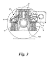
- Figure 3 shows the suspension arrangement of a second embodiment of bogie in accordance with the present invention and parts thereof which correspond to parts of the bogle shown in Figures 1 and 2 are denoted by the same reference numerals.
- the suspension arrangement shown in Figure 3 differs from that shown in Figures 1 and 2 by comprising different springs respectively above and below the axle centreline, which increases control of the lateral and longitudinal movements of the wheelset and hence the dynamic performance of the bogie.
- the suspension comprises two springs 21 which have their bases seated flat on the saddle or axlebox 13 above the axle, and two springs 14, one either side of the axle, which have their bases seated flat on the saddle or axlebox 13 below the axle centreline: all four springs 14,21 are aligned In the same longitudinal plane.
- the respective pedestal 20 of the bogie frame is supported directly on the upper ends of the springs 21 and indirectly, via friction wedges 17, on the tops of the springs 14.
- the two upper springs 21 may be replaced by a single such spring. In either case, the upper spring 21, or upper springs 21 overall, have a higher lateral spring rate than the lower springs 14.
- the bogie frame can accommodate a much greater load, for a particular spring of given dimension and rate, than they could in the conventional arrangement where such springs sit outside the inner wedge supporting springs. This is important, because the trend is towards a requirement to support greater loads per axle than before.
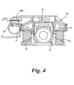
- a proportional load valve (PLV) 18 measures the apparent load on an axle and sends a pneumatic signal to the brake control valve which in turn controls the force, in response to the measured pressure, applied to the brake blocks which act on the wheels to slow the wagon.
- PLV proportional load valve
- the signal from the PLV 18 is generated by the compressive load applied to the coil suspension springs 14, 21 located in the saddle or axlebox assembly 13.
- the PLV is located on the top of one of the coil suspension springs 14, 21. This can lead to margins of error in recording the load acting on the axle.
- each bogie has a PLV.
- the load acting on a bogie is half the total mass of the wagon.
- a bogie has two axles therefore each axle sees one quarter of the total mass of the wagon. This is where the margin of error can arise.
- the PLV is located on top of one of the suspension springs it actually sees either a quarter of the load acting on the axle, in the case of Y25 bogie i.e. one spring either side of the saddle or axle box or on eighth of the load acting on the axle in the case of an Axle Motion Bogie i.e. two springs either side of the saddle or axle box.
- the error can arise because it is possible for the springs to be compressed in an unequal manner i.e. one side of the saddle or axle box could be compressed more than the other because of track deformities etc.
- the PLV to be fitted immediately above the axle when one spring is located above the centreline of the axle therefore to measure directly one quarter of the load acting on the axle or it can be fitted on the bogie frame and actuated by a 1:1 ratio lever 18a, which responds to the load applied to the axle on its vertical centreline. If two springs are used directly above the axle a 1:0.5 ratio lever activated by both springs simultaneously measures on quarter of the axle load.
- the novel approach of direct load sensing over the axle eliminates the margin of error associated with traditional load sensing from the side of the saddle or axlebox.
- the floating control arrangement of the friction wedges again provides vertical and lateral friction damping and permits and dampens longitudinal or yaw motion of the respective wheelset. Lateral forces are resisted by the upper springs in a double shear plane; such that the bending component of spring flexure is at a minimum.
- the overall lateral spring rate is relatively high such that the wheelset is better able to resist rail-to-wheel lateral forces and, in particular, any tendency for hunting on straight track.
- the upper and lower springs When subjected to longitudinal forces, the upper and lower springs deflect readily due to the combined action of bending moment and shear on two planes spaced about the axle centreline: the upper springs deflect, overall, at a lower rate than the lower springs, due to the axle forces on the saddle or axlebox causing rotation; the effect is a lowering of the overall spring rate, producing easier longitudinal wheelset steering.
- the response of the suspension to vertical loads is unchanged, as the vertical spring rates are equal for all springs.
- the bases of the springs rest flat and planar on their supports and, on the upper springs, they are constrained over part of their lengths such that pure shear will take place in the lateral planes.
- the lateral load portion on the upper spring plane is greater than on the lower spring plane, due to a larger bending couple from the top of the upper spring seat to the axle centreline.
- There is a larger load at the bases of the upper springs due to the larger bending couple, as the saddle or axlebox is caused to move in a level and co-planar manner under the action of lateral loads.
- bending is restricted and the overall lateral spring rate is increased because of the predominant shearing action, giving greater stability of the wheelset particularly when running in tare on straight track.
- the spring seats are still flat and planar but their ends are not constrained: the upper springs have a larger bending moment, for the reasons previously explained.
- the saddle or axlebox is caused to rotate slightly when displaced longitudinally and a more pure bending of the upper springs results: this is because the upper springs are closer to the vertical centroid of the axle longitudinal motion than the outer, lower springs, which are also under wedge action as a result of the longitudinal displacement.
- Both the upper and lower springs deflect by bending and in some part shear, with the upper springs taking a larger proportion of the forces and purely bending.
- the overall lateral spring rate in the longitudinal direction is reduced, leading to relatively easier steering, with the longitudinal forces arising from wheel-to-rail friction on curves, leading to effective self-steering.
- Figures 5 and 6 show one of the friction wedges 17 used in the suspensions of the two embodiments of bogie which have been described.
- Conventional friction wedges 17 are cambered along the inclined support surface 30 of the wedge 17 as shown in Figure 5 , but this surface is straight across the width of the wedge 17.
- the inclined surface 30 is cambered both along the inclined surface 30 of the wedge 17, and is also cambered across the width of the wedge, as shown in Figure 6 .
- the surface is thus convex-curved in both its longitudinal and transverse directions, providing a generally domed or spherical contact surface: there is therefore a reduction in the frictional contact area and an increase in the mean maximum pressure and thereby a reduction in the resistance of the wheelset to longitudinal movement and a more ready accommodation of saddle or axlebox 13 rotation in the horizontal plane.
- the bogie frame 19 accommodates various bogie equipment and in general is fabricated by welding together two side beams, one beam or bolster into an H shaped frame.
- the welded connection between an existing bolster and a side frame is achieved by fillet welding as shown in Figure 7A .
- Side frame 40 is welded to bolster 41 by fillet welds 42.
- fillet welds 42 the allowable stress level permitted on the joint between side frame and bolster is governed by the classification of a fillet weld (fillet welds are low classification welds).
- the bolster 45 is formed with an annular flange 46 that can be disposed within a generally circular aperture 47 of a wall of the side frame 40.
- the edges of the aperture 47 and the flange 46 are pointed so that they leave appropriate spaces for a circular double sided full pen weld 49.
- I-beams The strength/weight advantages of I-beams are well known and this novel approach to the interface between the bolster and the side frame takes full advantage of them. Once again it also places the weld in a low stress position and enables a high classification weld to be formed.
- the invention is intended to cover not only individual embodiments but also, combinations of the embodiments herein defined.
Landscapes
- Engineering & Computer Science (AREA)
- Mechanical Engineering (AREA)
- Springs (AREA)
- Devices For Conveying Motion By Means Of Endless Flexible Members (AREA)
- Gears, Cams (AREA)
- Pulleys (AREA)
- Vehicle Body Suspensions (AREA)
- Control Of Vehicles With Linear Motors And Vehicles That Are Magnetically Levitated (AREA)
Abstract
Description
- The present invention relates to bogies for railway rolling stock, and particularly but not solely to bogies for railway freight wagons.
- Railway bogies typically comprise a generally rectangular frame, arranged to be mounted via a bearing to the underside of the railway wagon chassis for turning about a central vertical axis, this bogie frame being mounted on a pair of wheelsets, each consisting of an axle having a wheel and a bearing fixed to it adjacent to each of its opposite ends. The wheelset is attached to the bogie frame via a saddle or axlebox assembly which encloses the bearing at each end of the wheelset. The saddle or axlebox has a number of coil suspension springs standing vertically. The bogie frame is provided with pedestal formations adjacent its four corners, the four pedestals being supported on the upper ends of the suspension springs of the four saddle or axlebox assemblies. This suspension arrangement is known as a primary suspension.
- In current arrangements, the suspension springs are disposed at a common level, either above or below the level of the axle centreline, such that the suspension therefore has a single plane of spring interaction and the springs can both shear and bend. In some other suspensions, the springs are arranged purely to bend in their axial planes. In considering the response of a helical coil spring to a lateral force, the deflection due to the bending moment and the deflection produced by the shearing force both have to be taken into account. In the case of a free helical spring supported flat at each end, the lateral force response can be considered equal at the 0,90,180 and 270 degree directions. The lateral spring rate varies with the seating conditions of the spring ends and with their rocking behaviour.
-
US-A-4932330 describes a suspension for a railcart wheel axle including a pair of springs on respective sides of the axle which are in turn mounted by further lower differently rated springs. -
US-A-2900924 describes a suspension for a railcart includes pairs of springs on respective sides of the axle in which the springs in the pairs are differently rated. - We have now devised bogies which exhibit improved performance in response to forces to which, in use, the suspension springs are subjected, such that the bogie exhibits improved self-steering and more easily absorbs lateral forces.
- In accordance with the present invention, there is a railway bogie as claimed in claim 1.
- In one embodiment, the springs of each suspension arrangement exhibit a first overall stiffness against forces laterally of the bogie, and a second, lower, overall stiffness against forces longitudinally of the bogie: the springs thus exhibit less deflection laterally than longitudinally. As a result, the bogie wheelset exhibits good resistance to lateral movement or hunting on straight track, and moves more readily longitudinally on curved track, so exhibiting improved self-steering. As a consequence, wheel wear is reduced.
- In one embodiment, each suspension arrangement comprises two inner springs, one either side of the wheelset axle, and two outer springs each side of the axle, further from the axle than the inner springs, Preferably the inner spring and two outer springs, each side of the axle, are arranged as a group in a triangle. Preferably each of the inner springs has twice the axial stiffness of each of the outer springs of the same group, so that the axial stiffness of the inner spring is matched by the combined axial stiffnesses of the two outer springs. Preferably the bogie frame rests on the tops of the inner springs via respective friction wedges, which give the bogie a floating control property, providing vertical and lateral friction damping, thus permitting and damping longitudinal or yaw motion of the wheelset.
- In a second embodiment, each suspension arrangement comprises two lower springs, one either side of the wheelset axle, and at least one upper spring disposed above the wheelset axle. In this arrangements, the overall stiffness against forces laterally of the bogie is relatively high. The bogie frame preferably rests on the tops of the lower springs via respective friction wedges. Preferably the upper springs are constrained, over part of their lengths, such that pure shear will take place in the lateral plane.
- It is preferred that the suspension arrangements of either the first or second embodiments of the invention include a proportional load valve (PLV) to measure apparent load on an axle.
- It is envisaged that the proportional load valve is fitted in vertical alignment with an axle, preferably substantially above a suspension spring fitted to a suspension frame or is arranged to measure the load applied directly through the axle e.g. by being connected to a point in the plane passing through the vertical centreline of the axle by a one to one lever,
- Preferably, the proportional load valve sends a pneumatic signal to a brake control valve which controls the force applied to brake blocks acting on the wheels.
- Conventional railway bogie friction wedges have their inclined contact surfaces cambered or convex-curved from end-to-end, but these surfaces are straight across the width of the wedge. Preferably, the inclined contact surface of each friction wedge is cambered or convex-curved both longitudinally and transversely, providing a generally domed surface and therefore a reduction in the contact area and an increase in mean maximum pressure thereby reducing resistance to longitudinal movement of the wheelset: this leads to a further improvement in the self-steering performance of the bogie.
- Embodiments of the present invention will now be described by way of examples only and with reference to the accompanying drawings, in which:
-
Figure 1 is a side view of the suspension arrangement at one corner of a first embodiment of self-steering railway bogie in accordance with the present invention; -
Figure 2 is a plan view of the arrangement shown inFigure 1 ; -
Figure 3 is a view, similar toFigure 1 , of the suspension arrangement of a second embodiment of self-steering railway bogie in accordance with the present invention; -
Figure 4 is a side view of the suspension arrangement at one corner of a modified second embodiment of self-steering railway bogie in accordance with the present invention; -
Figure 5 is a side view of one of the friction wedges (not claimed) used in the suspension arrangements of the bogies shown inFigures 1 to 3 ; -
Figure 6 is a section through the friction wedge, on the line V-V shown inFigure 5 ; -
Figure 7A shows a conventional weld joint between an existing bolster and side frame of a bogie; -
Figure 7B shows a weld join (not claimed) used in embodiments of the current invention where a full penetration butt weld is used; and -
Figure 8 illustrates an improvement ofFigure 7B wherein the interface is constructed to form an I-beam. - Referring firstly to
Figures 1 and2 of the drawings, a self-steering bogie comprises two wheelsets, one wheel of one such wheelset being shown at 10. Asaddle 13a oraxlebox assembly 13b is mounted to the end of the axle of the wheelset via a bearing 11 and abearing adapter 12, thesaddle 13a oraxlebox assembly 13b, (seeFigure 3 ) collectively referred to as 13 which provides flat seats, to either side of the axle, for respective sets of coiled suspension springs. Each set of suspension springs comprises three such springs, namely a first orinner spring 14, adjacent the axle, and then second and third orouter springs first spring 14 and symmetrically to either side of that springs The bases of the suspension springs are all below the axle centreline and may be all on the same level as each other, or slightly offset: for example, in the embodiment shown, the bases of theinner springs 14 are at a slightly higher level than the bases of theouter springs inner springs 14 supportrespective friction wedges 17, the upper surfaces of which are inclined downwardly away from the axle. The bogie further comprises a generallyrectangular frame 19, arranged to be mounted via a bearing to the underside of the wagon chassis for turning about a central vertical axis in conventional manner: the bogie frame is provided with apedestal formation 20 adjacent each of its four corners. Thepedestal 20 is supported directly on the upper ends of thesuspension springs friction wedges 17, on the upper ends of thesuspension springs 14. - It will be appreciated that bogie suspension uses a floating control wedge principle, the arrangement of the
friction wedges 17 providing vertical and lateral friction damping and permitting and damping longitudinal or yaw motion of the respective wheelset. Theinner springs 14 have twice the axial stiffness of each of theouter springs inner spring 14 is matched by the combined stiffness of the twoouter springs friction wedged 17 is maintained at the required level. It will be appreciated that the centre of resistive movement of each triangular group of springs is displaced to the centre of the triangle and this effectively increases the overall lateral stiffness: in particular, the overall lateral stiffness of each triangular group of springs is greater than the combined lateral stiffnesses of the individual springs of the group, whilst the overall longitudinal stiffness of the group is less than the combined lateral stiffness of the individual springs of the group. Lateral vehicle generated forces are accordingly resisted, by shear and bending of the groups of springs, to a greater degree than longitudinal track-generated (traction and creepage) forces. Consequently, each wheelset of the bogie is more resistant to lateral movement or hunting on straight track, and more ready to move longitudinally on curved track, giving good self-steering properties. As a further consequence, wheel wear is reduced. -
Figure 3 shows the suspension arrangement of a second embodiment of bogie in accordance with the present invention and parts thereof which correspond to parts of the bogle shown inFigures 1 and2 are denoted by the same reference numerals. The suspension arrangement shown inFigure 3 differs from that shown inFigures 1 and2 by comprising different springs respectively above and below the axle centreline, which increases control of the lateral and longitudinal movements of the wheelset and hence the dynamic performance of the bogie. In particular, the suspension comprises twosprings 21 which have their bases seated flat on the saddle oraxlebox 13 above the axle, and twosprings 14, one either side of the axle, which have their bases seated flat on the saddle oraxlebox 13 below the axle centreline: all foursprings respective pedestal 20 of the bogie frame is supported directly on the upper ends of thesprings 21 and indirectly, viafriction wedges 17, on the tops of thesprings 14. In a modification, the twoupper springs 21 may be replaced by a single such spring. In either case, theupper spring 21, orupper springs 21 overall, have a higher lateral spring rate than thelower springs 14. - It will be appreciated that by disposing the
springs 21 almost directly over the axle, the bogie frame can accommodate a much greater load, for a particular spring of given dimension and rate, than they could in the conventional arrangement where such springs sit outside the inner wedge supporting springs. This is important, because the trend is towards a requirement to support greater loads per axle than before. - It will also be observed that the distance between the axis of the axle and the centres of the
springs spring springs Figure 1 by having the basis of thesprings springs 14, as previously mentioned. - In
Figure 4 a proportional load valve (PLV) 18 measures the apparent load on an axle and sends a pneumatic signal to the brake control valve which in turn controls the force, in response to the measured pressure, applied to the brake blocks which act on the wheels to slow the wagon. When the wagon is unloaded, for example, this prevents 'over braking' and hence reduces the likelihood of flats being formed on the wheel. - The signal from the
PLV 18 is generated by the compressive load applied to the coil suspension springs 14, 21 located in the saddle oraxlebox assembly 13. The PLV is located on the top of one of the coil suspension springs 14, 21. This can lead to margins of error in recording the load acting on the axle. - Normally each bogie has a PLV. The load acting on a bogie is half the total mass of the wagon. A bogie has two axles therefore each axle sees one quarter of the total mass of the wagon. This is where the margin of error can arise. If the PLV is located on top of one of the suspension springs it actually sees either a quarter of the load acting on the axle, in the case of Y25 bogie i.e. one spring either side of the saddle or axle box or on eighth of the load acting on the axle in the case of an Axle Motion Bogie i.e. two springs either side of the saddle or axle box. The error can arise because it is possible for the springs to be compressed in an unequal manner i.e. one side of the saddle or axle box could be compressed more than the other because of track deformities etc.
- In a preferred arrangement the PLV to be fitted immediately above the axle when one spring is located above the centreline of the axle therefore to measure directly one quarter of the load acting on the axle or it can be fitted on the bogie frame and actuated by a 1:1
ratio lever 18a, which responds to the load applied to the axle on its vertical centreline. If two springs are used directly above the axle a 1:0.5 ratio lever activated by both springs simultaneously measures on quarter of the axle load. The novel approach of direct load sensing over the axle eliminates the margin of error associated with traditional load sensing from the side of the saddle or axlebox. - The floating control arrangement of the friction wedges again provides vertical and lateral friction damping and permits and dampens longitudinal or yaw motion of the respective wheelset. Lateral forces are resisted by the upper springs in a double shear plane; such that the bending component of spring flexure is at a minimum. The overall lateral spring rate is relatively high such that the wheelset is better able to resist rail-to-wheel lateral forces and, in particular, any tendency for hunting on straight track. When subjected to longitudinal forces, the upper and lower springs deflect readily due to the combined action of bending moment and shear on two planes spaced about the axle centreline: the upper springs deflect, overall, at a lower rate than the lower springs, due to the axle forces on the saddle or axlebox causing rotation; the effect is a lowering of the overall spring rate, producing easier longitudinal wheelset steering. In either condition of lateral or longitudinal loading or forces, the response of the suspension to vertical loads is unchanged, as the vertical spring rates are equal for all springs.
- The bases of the springs rest flat and planar on their supports and, on the upper springs, they are constrained over part of their lengths such that pure shear will take place in the lateral planes. As has been previously mentioned, the lateral load portion on the upper spring plane is greater than on the lower spring plane, due to a larger bending couple from the top of the upper spring seat to the axle centreline. There is a larger load at the bases of the upper springs due to the larger bending couple, as the saddle or axlebox is caused to move in a level and co-planar manner under the action of lateral loads. However, bending is restricted and the overall lateral spring rate is increased because of the predominant shearing action, giving greater stability of the wheelset particularly when running in tare on straight track. Under longitudinal forces, the spring seats are still flat and planar but their ends are not constrained: the upper springs have a larger bending moment, for the reasons previously explained. In addition, the saddle or axlebox is caused to rotate slightly when displaced longitudinally and a more pure bending of the upper springs results: this is because the upper springs are closer to the vertical centroid of the axle longitudinal motion than the outer, lower springs, which are also under wedge action as a result of the longitudinal displacement. Both the upper and lower springs deflect by bending and in some part shear, with the upper springs taking a larger proportion of the forces and purely bending. The overall lateral spring rate in the longitudinal direction is reduced, leading to relatively easier steering, with the longitudinal forces arising from wheel-to-rail friction on curves, leading to effective self-steering.
-
Figures 5 and 6 show one of thefriction wedges 17 used in the suspensions of the two embodiments of bogie which have been described.Conventional friction wedges 17 are cambered along theinclined support surface 30 of thewedge 17 as shown inFigure 5 , but this surface is straight across the width of thewedge 17. In accordance with the present invention, theinclined surface 30 is cambered both along theinclined surface 30 of thewedge 17, and is also cambered across the width of the wedge, as shown inFigure 6 . The surface is thus convex-curved in both its longitudinal and transverse directions, providing a generally domed or spherical contact surface: there is therefore a reduction in the frictional contact area and an increase in the mean maximum pressure and thereby a reduction in the resistance of the wheelset to longitudinal movement and a more ready accommodation of saddle oraxlebox 13 rotation in the horizontal plane. These factors lead to a further improvement in the self-steering performance of the bogie. - The
bogie frame 19 accommodates various bogie equipment and in general is fabricated by welding together two side beams, one beam or bolster into an H shaped frame. Conventionally, the welded connection between an existing bolster and a side frame is achieved by fillet welding as shown inFigure 7A .Side frame 40 is welded to bolster 41 by fillet welds 42. By using fillet welds 42, the allowable stress level permitted on the joint between side frame and bolster is governed by the classification of a fillet weld (fillet welds are low classification welds). However with applicants arrangement as shown inFigure 7B there is the ability to increase the level of weld classification by using a butt weld, such as a full (or complete) penetration butt weld which gives an increase in the allowable stress. This is achieved by forming part of the inner wall of theframe 40 integrally on the bolster so that thewelds 43 are moved outwardly to form butt welds. Further by cutting away the outer walls from 40 further butt welds can be formed at 44. The applicants construction also moves the welded connection into a lower stress region. The combination of improved weld classification and position thereby provides a more structurally efficient design. A further improvement is shown inFigure 8 where the bolster side frame interface is constructed to form an I-beam with the side frame; the web of the I-beam being located in the plane of the bogie journals. - Thus the bolster 45 is formed with an
annular flange 46 that can be disposed within a generallycircular aperture 47 of a wall of theside frame 40. The edges of theaperture 47 and theflange 46 are pointed so that they leave appropriate spaces for a circular double sidedfull pen weld 49. - The strength/weight advantages of I-beams are well known and this novel approach to the interface between the bolster and the side frame takes full advantage of them. Once again it also places the weld in a low stress position and enables a high classification weld to be formed.
- The invention is intended to cover not only individual embodiments but also, combinations of the embodiments herein defined.
Claims (9)
- A railway bogie including an elongate bogie frame (19) supported on a plurality of wheelset axles by respective suspension arrangements, each arrangement including a plurality of springs (14, 15, 16, 21) which exhibit a first overall response to forces laterally of the bogie and a second different response to forces longitudinally of the bogie wherein each suspension arrangement includes two lower springs (14) on either side of its wheel axle and at least one upper spring (21) disposed above the wheel axle characterised in that the bogie further includes a proportional load valve (PLV) (18) for producing an output signal indicative of the load applied to the axle in its vertical centre plane.
- A bogie as claimed in claim 1 wherein each suspension arrangement exhibits a first overall stiffness against forces laterally of the bogie and a second, lower, overall stiffness against forces longitudinally of the bogie.
- A bogie as claimed in claim 1 or claim 2 wherein each suspension arrangement includes a group of springs (14,15,18) on either side of its axle, each group comprising an inner spring (14) adjacent the axle and a pair of fore and aft outer springs (15,16).
- A bogie as claimed in claim 3 wherein the springs (14, 15, 16) in a group are arranged in a triangle.
- A bogie as claimed in claim 3 or claim 4 wherein the inner spring (14) in a group has twice the axial stiffness of each of the outer springs (15,16).
- A bogie as claimed in claim 5 wherein the bogie frame (19) rests on the top of the inner springs (14) via respective friction wedges (17).
- A bogie as claimed in claim 1 wherein the bogie frame (19) rests on the top of the lower spring via (14) respective friction wedges (17)
- A bogie as claimed in claim 6 wherein the surface of the friction wedge (17) that supports the bogie frame (19) is cambered or convex curved both longitudinal and laterally.
- A bogie as claimed in any one of the preceding claims wherein at least one of the springs (14, 15, 16, 21) is received in a pocket or pockets to reduce its effective length in shear.
Applications Claiming Priority (2)
| Application Number | Priority Date | Filing Date | Title |
|---|---|---|---|
| GBGB0500236.5A GB0500236D0 (en) | 2005-01-07 | 2005-01-07 | Railway bogies |
| PCT/GB2006/000052 WO2006072800A1 (en) | 2005-01-07 | 2006-01-06 | Railway bogies |
Publications (2)
| Publication Number | Publication Date |
|---|---|
| EP1833710A1 EP1833710A1 (en) | 2007-09-19 |
| EP1833710B1 true EP1833710B1 (en) | 2011-03-09 |
Family
ID=34203722
Family Applications (1)
| Application Number | Title | Priority Date | Filing Date |
|---|---|---|---|
| EP06709540A Expired - Lifetime EP1833710B1 (en) | 2005-01-07 | 2006-01-06 | Railway bogies |
Country Status (11)
| Country | Link |
|---|---|
| US (1) | US7908974B2 (en) |
| EP (1) | EP1833710B1 (en) |
| CN (1) | CN101098808A (en) |
| AT (1) | ATE501012T1 (en) |
| AU (1) | AU2006204395A1 (en) |
| BR (1) | BRPI0606498A2 (en) |
| CA (1) | CA2593147A1 (en) |
| DE (1) | DE602006020541D1 (en) |
| GB (1) | GB0500236D0 (en) |
| RU (1) | RU2007129922A (en) |
| WO (1) | WO2006072800A1 (en) |
Families Citing this family (22)
| Publication number | Priority date | Publication date | Assignee | Title |
|---|---|---|---|---|
| US20090242335A1 (en) * | 2006-07-11 | 2009-10-01 | Sct Europe Limited | Railway Bogies |
| GB0708257D0 (en) * | 2007-04-28 | 2007-06-06 | Sct Europ Ltd | Suspension for a rail vehicle |
| GB0711383D0 (en) * | 2007-06-13 | 2007-07-25 | Sct Europ Ltd | Suspension for a rail vehicle |
| RU2375223C2 (en) * | 2007-11-09 | 2009-12-10 | Открытое акционерное общество "Кировский Машзавод 1 Мая" | Bogie |
| US8104409B2 (en) | 2008-08-19 | 2012-01-31 | Bradken Resources Pty Limited | Rail car suspension damping |
| US8443735B2 (en) * | 2009-01-14 | 2013-05-21 | General Electric Company | Vehicle and truck assembly |
| US8136456B2 (en) * | 2009-08-13 | 2012-03-20 | Wabtec Corporation | Friction wedge for railroad car truck |
| US8905386B2 (en) * | 2011-11-21 | 2014-12-09 | Chrysler Group Llc | Three-stage concentric coil spring system |
| US8661988B2 (en) * | 2012-02-29 | 2014-03-04 | Electromotive-Diesel, Inc. | Railway truck having axle-pinned equalizer |
| WO2014165173A1 (en) * | 2013-03-12 | 2014-10-09 | Subsidence, Inc. | Mechanical strain-based weather sensor |
| JP5820842B2 (en) * | 2013-05-08 | 2015-11-24 | 富士重工業株式会社 | Wheel reaction force detection device |
| US9434395B2 (en) * | 2013-06-27 | 2016-09-06 | Electro-Motive Diesel, Inc. | Fabricated frame for railway truck |
| WO2015159085A1 (en) * | 2014-04-16 | 2015-10-22 | Wabtec Rail Scotland Limited | Suspension module for a rail vehicle |
| EP3045372B1 (en) | 2015-01-19 | 2020-02-26 | VR-Yhtymä Oy | Spring-enhanched friction damper supported by a joint |
| EP3045374B1 (en) | 2015-01-19 | 2020-02-26 | VR-Yhtymä Oy | Weighing arrangement |
| EP3045373B1 (en) | 2015-01-19 | 2020-03-04 | VR-Yhtymä Oy | Friction damper supported by a joint |
| RU2607901C1 (en) * | 2015-07-31 | 2017-01-11 | Федеральное государственное бюджетное образовательное учреждение высшего профессионального образования "Елецкий государственный университет им. И.А. Бунина" | Three-axle non-pedestal diesel locomotive bogie |
| JP6577834B2 (en) * | 2015-10-29 | 2019-09-18 | 川崎重工業株式会社 | Railcar steering wheel |
| EP3752402B1 (en) | 2018-03-27 | 2022-03-23 | Siemens Mobility Austria GmbH | Running gear for a rail vehicle |
| RU184309U1 (en) * | 2018-05-14 | 2018-10-22 | Акционерное общество "Научно-внедренческий центр "Вагоны" (АО "НВЦ "Вагоны") | TRUCK CAR |
| US11414107B2 (en) * | 2019-10-22 | 2022-08-16 | National Steel Car Limited | Railroad car truck damper wedge fittings |
| CN112849190B (en) * | 2021-03-29 | 2024-10-11 | 中车齐齐哈尔车辆有限公司 | Axle box suspension device and bogie |
Family Cites Families (21)
| Publication number | Priority date | Publication date | Assignee | Title |
|---|---|---|---|---|
| US2132387A (en) * | 1938-01-20 | 1938-10-11 | Symington Gould Corp | Railway truck |
| US2355450A (en) * | 1942-02-14 | 1944-08-08 | Standard Car Truck Co | Car truck |
| US2900924A (en) * | 1956-06-13 | 1959-08-25 | Acf Ind Inc | Vehicle truck |
| US3936097A (en) * | 1973-05-30 | 1976-02-03 | Jidosha Kiki Co., Ltd. | Relay valve combined with a load-sensing proportion valve |
| GB1439655A (en) | 1973-06-22 | 1976-06-16 | British Steel Corp | Railway bogies |
| US3862606A (en) * | 1973-06-29 | 1975-01-28 | Brian T Scales | Radial truck |
| FR2302225A1 (en) | 1975-02-25 | 1976-09-24 | Paris & Outreau Acieries | BOGIE FOR RAILWAY ROLLING STOCK AS WELL AS ITS MANUFACTURING PROCESS |
| GB2078646B (en) | 1980-06-04 | 1983-09-07 | British Steel Corp | Railway bogie |
| US4932330A (en) | 1983-08-12 | 1990-06-12 | Bombardier Corporation | Primary suspension system for a railway car |
| US4676172A (en) * | 1983-12-02 | 1987-06-30 | Standard Research And Design Corp. | Frameless radial truck |
| SE446708B (en) * | 1984-11-22 | 1986-10-06 | Asea Ab | DAMAGE DEVICE BAGGY FOR RELAYING VEHICLES |
| FR2658471B1 (en) * | 1990-02-21 | 1992-06-12 | Sambre & Meuse Usines | LOAD WEIGHING BOGIE FOR RAILWAY VEHICLES. |
| US5176083A (en) * | 1991-04-23 | 1993-01-05 | Standard Car Truck Company | Railroad car truck damping member with open cavity and support rib construction |
| US5239932A (en) | 1992-06-15 | 1993-08-31 | National Castings Inc. | Force dampening mechanism of a railroad car truck |
| US5522468A (en) * | 1993-09-22 | 1996-06-04 | Dohrmann; David K. | Onboard weight indicator for measuring the load applied to a vehicle axle |
| US5611284A (en) | 1996-01-19 | 1997-03-18 | Atchison Casting Corporation | Rail truck suspension and journal housing retention assembly |
| US6092469A (en) * | 1998-05-13 | 2000-07-25 | Monsell; Dale | Radially side mounted railway car truck |
| US7129425B2 (en) * | 2003-03-26 | 2006-10-31 | Ensco, Inc. | Axle vertical load measurement device and method |
| JP4517648B2 (en) * | 2003-05-22 | 2010-08-04 | 日本精工株式会社 | Load measuring device for rolling bearing units |
| US7416262B2 (en) * | 2004-06-09 | 2008-08-26 | Wabtec Holding Corp. | Brake system with integrated car load compensating arrangement |
| GB0708257D0 (en) * | 2007-04-28 | 2007-06-06 | Sct Europ Ltd | Suspension for a rail vehicle |
-
2005
- 2005-01-07 GB GBGB0500236.5A patent/GB0500236D0/en not_active Ceased
-
2006
- 2006-01-06 AU AU2006204395A patent/AU2006204395A1/en not_active Abandoned
- 2006-01-06 US US11/794,388 patent/US7908974B2/en not_active Expired - Fee Related
- 2006-01-06 CA CA002593147A patent/CA2593147A1/en not_active Abandoned
- 2006-01-06 AT AT06709540T patent/ATE501012T1/en not_active IP Right Cessation
- 2006-01-06 RU RU2007129922/11A patent/RU2007129922A/en not_active Application Discontinuation
- 2006-01-06 DE DE602006020541T patent/DE602006020541D1/en not_active Expired - Lifetime
- 2006-01-06 BR BRPI0606498-1A patent/BRPI0606498A2/en not_active IP Right Cessation
- 2006-01-06 EP EP06709540A patent/EP1833710B1/en not_active Expired - Lifetime
- 2006-01-06 WO PCT/GB2006/000052 patent/WO2006072800A1/en not_active Ceased
- 2006-01-06 CN CNA2006800018403A patent/CN101098808A/en active Pending
Also Published As
| Publication number | Publication date |
|---|---|
| BRPI0606498A2 (en) | 2010-01-26 |
| WO2006072800A1 (en) | 2006-07-13 |
| RU2007129922A (en) | 2009-02-20 |
| DE602006020541D1 (en) | 2011-04-21 |
| CN101098808A (en) | 2008-01-02 |
| GB0500236D0 (en) | 2005-02-16 |
| EP1833710A1 (en) | 2007-09-19 |
| CA2593147A1 (en) | 2006-07-13 |
| ATE501012T1 (en) | 2011-03-15 |
| AU2006204395A1 (en) | 2006-07-13 |
| US7908974B2 (en) | 2011-03-22 |
| US20090031918A1 (en) | 2009-02-05 |
Similar Documents
| Publication | Publication Date | Title |
|---|---|---|
| US7908974B2 (en) | Railway bogies | |
| AU2004202601B2 (en) | Three-piece Motion Control Truck System | |
| US7610862B2 (en) | Rail road car truck with rocking sideframe | |
| EP1556265B1 (en) | Railroad freight car truck suspension yaw stabilizer, and corresponding method | |
| US4003316A (en) | Articulated railway car trucks | |
| US20160001796A1 (en) | Truck and sideframe therefor | |
| WO1993000243A1 (en) | Stabilized swing-motion truck for railway cars | |
| CN102700560A (en) | Rail road car truck and members thereof | |
| US5331902A (en) | Truck boltser with laterally wider friction show pocket and mechanism for lateral travel of the friction shoe | |
| CN111301471A (en) | Railway vehicle bogie | |
| AU2004202641B2 (en) | Multi-purpose Universal Sideframe for Railway Trucks | |
| US4771704A (en) | Damping device in a bogie for a railbound vehicle | |
| WO2000013954A1 (en) | 3-piece rail bogie | |
| RU2292282C1 (en) | Freight-car bogie | |
| US12570334B2 (en) | Multi-unit railroad car and railroad car trucks therefor | |
| CA2797275C (en) | Rail road car truck with rocking sideframe | |
| RU223227U1 (en) | FREIGHT CAR | |
| RU2275308C2 (en) | Freight car two-axle bogie | |
| CN119428782A (en) | Three-axle welded bogie and rail vehicle | |
| UA82338C2 (en) | Cart of freight railroad car | |
| CA2872781A1 (en) | Rail road car truck with rocking sideframe | |
| AU1240192A (en) | Stabilized swing-motion truck for railway cars | |
| UA19122U (en) | Four-wheel bogie for freight railroad cars of main railroads |
Legal Events
| Date | Code | Title | Description |
|---|---|---|---|
| PUAI | Public reference made under article 153(3) epc to a published international application that has entered the european phase |
Free format text: ORIGINAL CODE: 0009012 |
|
| 17P | Request for examination filed |
Effective date: 20070726 |
|
| AK | Designated contracting states |
Kind code of ref document: A1 Designated state(s): AT BE BG CH CY CZ DE DK EE ES FI FR GB GR HU IE IS IT LI LT LU LV MC NL PL PT RO SE SI SK TR |
|
| DAX | Request for extension of the european patent (deleted) | ||
| 17Q | First examination report despatched |
Effective date: 20090212 |
|
| GRAP | Despatch of communication of intention to grant a patent |
Free format text: ORIGINAL CODE: EPIDOSNIGR1 |
|
| GRAC | Information related to communication of intention to grant a patent modified |
Free format text: ORIGINAL CODE: EPIDOSCIGR1 |
|
| GRAS | Grant fee paid |
Free format text: ORIGINAL CODE: EPIDOSNIGR3 |
|
| GRAA | (expected) grant |
Free format text: ORIGINAL CODE: 0009210 |
|
| AK | Designated contracting states |
Kind code of ref document: B1 Designated state(s): AT BE BG CH CY CZ DE DK EE ES FI FR GB GR HU IE IS IT LI LT LU LV MC NL PL PT RO SE SI SK TR |
|
| REG | Reference to a national code |
Ref country code: GB Ref legal event code: FG4D |
|
| REG | Reference to a national code |
Ref country code: CH Ref legal event code: EP |
|
| REG | Reference to a national code |
Ref country code: IE Ref legal event code: FG4D |
|
| REF | Corresponds to: |
Ref document number: 602006020541 Country of ref document: DE Date of ref document: 20110421 Kind code of ref document: P |
|
| REG | Reference to a national code |
Ref country code: DE Ref legal event code: R096 Ref document number: 602006020541 Country of ref document: DE Effective date: 20110421 |
|
| REG | Reference to a national code |
Ref country code: SE Ref legal event code: TRGR |
|
| REG | Reference to a national code |
Ref country code: NL Ref legal event code: VDEP Effective date: 20110309 |
|
| PG25 | Lapsed in a contracting state [announced via postgrant information from national office to epo] |
Ref country code: LV Free format text: LAPSE BECAUSE OF FAILURE TO SUBMIT A TRANSLATION OF THE DESCRIPTION OR TO PAY THE FEE WITHIN THE PRESCRIBED TIME-LIMIT Effective date: 20110309 Ref country code: ES Free format text: LAPSE BECAUSE OF FAILURE TO SUBMIT A TRANSLATION OF THE DESCRIPTION OR TO PAY THE FEE WITHIN THE PRESCRIBED TIME-LIMIT Effective date: 20110620 Ref country code: LT Free format text: LAPSE BECAUSE OF FAILURE TO SUBMIT A TRANSLATION OF THE DESCRIPTION OR TO PAY THE FEE WITHIN THE PRESCRIBED TIME-LIMIT Effective date: 20110309 Ref country code: GR Free format text: LAPSE BECAUSE OF FAILURE TO SUBMIT A TRANSLATION OF THE DESCRIPTION OR TO PAY THE FEE WITHIN THE PRESCRIBED TIME-LIMIT Effective date: 20110610 |
|
| LTIE | Lt: invalidation of european patent or patent extension |
Effective date: 20110309 |
|
| PG25 | Lapsed in a contracting state [announced via postgrant information from national office to epo] |
Ref country code: BG Free format text: LAPSE BECAUSE OF FAILURE TO SUBMIT A TRANSLATION OF THE DESCRIPTION OR TO PAY THE FEE WITHIN THE PRESCRIBED TIME-LIMIT Effective date: 20110609 Ref country code: AT Free format text: LAPSE BECAUSE OF FAILURE TO SUBMIT A TRANSLATION OF THE DESCRIPTION OR TO PAY THE FEE WITHIN THE PRESCRIBED TIME-LIMIT Effective date: 20110309 Ref country code: NL Free format text: LAPSE BECAUSE OF FAILURE TO SUBMIT A TRANSLATION OF THE DESCRIPTION OR TO PAY THE FEE WITHIN THE PRESCRIBED TIME-LIMIT Effective date: 20110309 Ref country code: FI Free format text: LAPSE BECAUSE OF FAILURE TO SUBMIT A TRANSLATION OF THE DESCRIPTION OR TO PAY THE FEE WITHIN THE PRESCRIBED TIME-LIMIT Effective date: 20110309 Ref country code: CY Free format text: LAPSE BECAUSE OF FAILURE TO SUBMIT A TRANSLATION OF THE DESCRIPTION OR TO PAY THE FEE WITHIN THE PRESCRIBED TIME-LIMIT Effective date: 20110309 Ref country code: SI Free format text: LAPSE BECAUSE OF FAILURE TO SUBMIT A TRANSLATION OF THE DESCRIPTION OR TO PAY THE FEE WITHIN THE PRESCRIBED TIME-LIMIT Effective date: 20110309 |
|
| PG25 | Lapsed in a contracting state [announced via postgrant information from national office to epo] |
Ref country code: BE Free format text: LAPSE BECAUSE OF FAILURE TO SUBMIT A TRANSLATION OF THE DESCRIPTION OR TO PAY THE FEE WITHIN THE PRESCRIBED TIME-LIMIT Effective date: 20110309 |
|
| PG25 | Lapsed in a contracting state [announced via postgrant information from national office to epo] |
Ref country code: PT Free format text: LAPSE BECAUSE OF FAILURE TO SUBMIT A TRANSLATION OF THE DESCRIPTION OR TO PAY THE FEE WITHIN THE PRESCRIBED TIME-LIMIT Effective date: 20110711 Ref country code: EE Free format text: LAPSE BECAUSE OF FAILURE TO SUBMIT A TRANSLATION OF THE DESCRIPTION OR TO PAY THE FEE WITHIN THE PRESCRIBED TIME-LIMIT Effective date: 20110309 |
|
| PG25 | Lapsed in a contracting state [announced via postgrant information from national office to epo] |
Ref country code: SK Free format text: LAPSE BECAUSE OF FAILURE TO SUBMIT A TRANSLATION OF THE DESCRIPTION OR TO PAY THE FEE WITHIN THE PRESCRIBED TIME-LIMIT Effective date: 20110309 Ref country code: CZ Free format text: LAPSE BECAUSE OF FAILURE TO SUBMIT A TRANSLATION OF THE DESCRIPTION OR TO PAY THE FEE WITHIN THE PRESCRIBED TIME-LIMIT Effective date: 20110309 Ref country code: IS Free format text: LAPSE BECAUSE OF FAILURE TO SUBMIT A TRANSLATION OF THE DESCRIPTION OR TO PAY THE FEE WITHIN THE PRESCRIBED TIME-LIMIT Effective date: 20110709 Ref country code: RO Free format text: LAPSE BECAUSE OF FAILURE TO SUBMIT A TRANSLATION OF THE DESCRIPTION OR TO PAY THE FEE WITHIN THE PRESCRIBED TIME-LIMIT Effective date: 20110309 |
|
| PLBE | No opposition filed within time limit |
Free format text: ORIGINAL CODE: 0009261 |
|
| STAA | Information on the status of an ep patent application or granted ep patent |
Free format text: STATUS: NO OPPOSITION FILED WITHIN TIME LIMIT |
|
| 26N | No opposition filed |
Effective date: 20111212 |
|
| PG25 | Lapsed in a contracting state [announced via postgrant information from national office to epo] |
Ref country code: DK Free format text: LAPSE BECAUSE OF FAILURE TO SUBMIT A TRANSLATION OF THE DESCRIPTION OR TO PAY THE FEE WITHIN THE PRESCRIBED TIME-LIMIT Effective date: 20110309 Ref country code: PL Free format text: LAPSE BECAUSE OF FAILURE TO SUBMIT A TRANSLATION OF THE DESCRIPTION OR TO PAY THE FEE WITHIN THE PRESCRIBED TIME-LIMIT Effective date: 20110309 |
|
| REG | Reference to a national code |
Ref country code: DE Ref legal event code: R097 Ref document number: 602006020541 Country of ref document: DE Effective date: 20111212 |
|
| PG25 | Lapsed in a contracting state [announced via postgrant information from national office to epo] |
Ref country code: IT Free format text: LAPSE BECAUSE OF FAILURE TO SUBMIT A TRANSLATION OF THE DESCRIPTION OR TO PAY THE FEE WITHIN THE PRESCRIBED TIME-LIMIT Effective date: 20110309 |
|
| PG25 | Lapsed in a contracting state [announced via postgrant information from national office to epo] |
Ref country code: MC Free format text: LAPSE BECAUSE OF NON-PAYMENT OF DUE FEES Effective date: 20120131 |
|
| REG | Reference to a national code |
Ref country code: CH Ref legal event code: PL |
|
| REG | Reference to a national code |
Ref country code: IE Ref legal event code: MM4A |
|
| PG25 | Lapsed in a contracting state [announced via postgrant information from national office to epo] |
Ref country code: LI Free format text: LAPSE BECAUSE OF NON-PAYMENT OF DUE FEES Effective date: 20120131 Ref country code: CH Free format text: LAPSE BECAUSE OF NON-PAYMENT OF DUE FEES Effective date: 20120131 |
|
| PG25 | Lapsed in a contracting state [announced via postgrant information from national office to epo] |
Ref country code: IE Free format text: LAPSE BECAUSE OF NON-PAYMENT OF DUE FEES Effective date: 20120106 |
|
| PGFP | Annual fee paid to national office [announced via postgrant information from national office to epo] |
Ref country code: FR Payment date: 20130211 Year of fee payment: 8 |
|
| PG25 | Lapsed in a contracting state [announced via postgrant information from national office to epo] |
Ref country code: TR Free format text: LAPSE BECAUSE OF FAILURE TO SUBMIT A TRANSLATION OF THE DESCRIPTION OR TO PAY THE FEE WITHIN THE PRESCRIBED TIME-LIMIT Effective date: 20110309 |
|
| PG25 | Lapsed in a contracting state [announced via postgrant information from national office to epo] |
Ref country code: LU Free format text: LAPSE BECAUSE OF NON-PAYMENT OF DUE FEES Effective date: 20120106 |
|
| PG25 | Lapsed in a contracting state [announced via postgrant information from national office to epo] |
Ref country code: HU Free format text: LAPSE BECAUSE OF FAILURE TO SUBMIT A TRANSLATION OF THE DESCRIPTION OR TO PAY THE FEE WITHIN THE PRESCRIBED TIME-LIMIT Effective date: 20060106 |
|
| REG | Reference to a national code |
Ref country code: FR Ref legal event code: ST Effective date: 20140930 |
|
| PG25 | Lapsed in a contracting state [announced via postgrant information from national office to epo] |
Ref country code: FR Free format text: LAPSE BECAUSE OF NON-PAYMENT OF DUE FEES Effective date: 20140131 |
|
| PGFP | Annual fee paid to national office [announced via postgrant information from national office to epo] |
Ref country code: GB Payment date: 20171221 Year of fee payment: 13 |
|
| PGFP | Annual fee paid to national office [announced via postgrant information from national office to epo] |
Ref country code: DE Payment date: 20180123 Year of fee payment: 13 |
|
| PGFP | Annual fee paid to national office [announced via postgrant information from national office to epo] |
Ref country code: SE Payment date: 20180126 Year of fee payment: 13 |
|
| REG | Reference to a national code |
Ref country code: DE Ref legal event code: R119 Ref document number: 602006020541 Country of ref document: DE |
|
| GBPC | Gb: european patent ceased through non-payment of renewal fee |
Effective date: 20190106 |
|
| PG25 | Lapsed in a contracting state [announced via postgrant information from national office to epo] |
Ref country code: DE Free format text: LAPSE BECAUSE OF NON-PAYMENT OF DUE FEES Effective date: 20190801 Ref country code: SE Free format text: LAPSE BECAUSE OF NON-PAYMENT OF DUE FEES Effective date: 20190107 |
|
| PG25 | Lapsed in a contracting state [announced via postgrant information from national office to epo] |
Ref country code: GB Free format text: LAPSE BECAUSE OF NON-PAYMENT OF DUE FEES Effective date: 20190106 |