EP1833659B1 - Method and apparatus for controlling the gap between the horn and the anvil of an ultrasonic welding system - Google Patents
Method and apparatus for controlling the gap between the horn and the anvil of an ultrasonic welding system Download PDFInfo
- Publication number
- EP1833659B1 EP1833659B1 EP05855841.2A EP05855841A EP1833659B1 EP 1833659 B1 EP1833659 B1 EP 1833659B1 EP 05855841 A EP05855841 A EP 05855841A EP 1833659 B1 EP1833659 B1 EP 1833659B1
- Authority
- EP
- European Patent Office
- Prior art keywords
- horn
- anvil
- freedom
- longitudinal axis
- ultrasonic welding
- Prior art date
- Legal status (The legal status is an assumption and is not a legal conclusion. Google has not performed a legal analysis and makes no representation as to the accuracy of the status listed.)
- Active
Links
- 238000003466 welding Methods 0.000 title claims description 48
- 238000000034 method Methods 0.000 title claims description 21
- 230000008569 process Effects 0.000 description 8
- 238000000429 assembly Methods 0.000 description 5
- 230000001276 controlling effect Effects 0.000 description 4
- 239000000758 substrate Substances 0.000 description 4
- 230000007246 mechanism Effects 0.000 description 3
- 210000004712 air sac Anatomy 0.000 description 2
- 230000000712 assembly Effects 0.000 description 2
- 238000005304 joining Methods 0.000 description 2
- 238000004519 manufacturing process Methods 0.000 description 2
- 230000004044 response Effects 0.000 description 2
- 238000013519 translation Methods 0.000 description 2
- NCGICGYLBXGBGN-UHFFFAOYSA-N 3-morpholin-4-yl-1-oxa-3-azonia-2-azanidacyclopent-3-en-5-imine;hydrochloride Chemical compound Cl.[N-]1OC(=N)C=[N+]1N1CCOCC1 NCGICGYLBXGBGN-UHFFFAOYSA-N 0.000 description 1
- 230000008878 coupling Effects 0.000 description 1
- 238000010168 coupling process Methods 0.000 description 1
- 238000005859 coupling reaction Methods 0.000 description 1
- 238000010586 diagram Methods 0.000 description 1
- 238000004049 embossing Methods 0.000 description 1
- 239000004744 fabric Substances 0.000 description 1
- 238000012886 linear function Methods 0.000 description 1
- 238000012986 modification Methods 0.000 description 1
- 230000004048 modification Effects 0.000 description 1
- 238000012544 monitoring process Methods 0.000 description 1
- 230000002093 peripheral effect Effects 0.000 description 1
- 230000001105 regulatory effect Effects 0.000 description 1
- 229920001169 thermoplastic Polymers 0.000 description 1
- 239000004416 thermosoftening plastic Substances 0.000 description 1
Images


Classifications
-
- B—PERFORMING OPERATIONS; TRANSPORTING
- B06—GENERATING OR TRANSMITTING MECHANICAL VIBRATIONS IN GENERAL
- B06B—METHODS OR APPARATUS FOR GENERATING OR TRANSMITTING MECHANICAL VIBRATIONS OF INFRASONIC, SONIC, OR ULTRASONIC FREQUENCY, e.g. FOR PERFORMING MECHANICAL WORK IN GENERAL
- B06B3/00—Methods or apparatus specially adapted for transmitting mechanical vibrations of infrasonic, sonic, or ultrasonic frequency
-
- B—PERFORMING OPERATIONS; TRANSPORTING
- B23—MACHINE TOOLS; METAL-WORKING NOT OTHERWISE PROVIDED FOR
- B23K—SOLDERING OR UNSOLDERING; WELDING; CLADDING OR PLATING BY SOLDERING OR WELDING; CUTTING BY APPLYING HEAT LOCALLY, e.g. FLAME CUTTING; WORKING BY LASER BEAM
- B23K20/00—Non-electric welding by applying impact or other pressure, with or without the application of heat, e.g. cladding or plating
- B23K20/10—Non-electric welding by applying impact or other pressure, with or without the application of heat, e.g. cladding or plating making use of vibrations, e.g. ultrasonic welding
- B23K20/103—Non-electric welding by applying impact or other pressure, with or without the application of heat, e.g. cladding or plating making use of vibrations, e.g. ultrasonic welding using a roller
-
- B—PERFORMING OPERATIONS; TRANSPORTING
- B23—MACHINE TOOLS; METAL-WORKING NOT OTHERWISE PROVIDED FOR
- B23K—SOLDERING OR UNSOLDERING; WELDING; CLADDING OR PLATING BY SOLDERING OR WELDING; CUTTING BY APPLYING HEAT LOCALLY, e.g. FLAME CUTTING; WORKING BY LASER BEAM
- B23K20/00—Non-electric welding by applying impact or other pressure, with or without the application of heat, e.g. cladding or plating
- B23K20/26—Auxiliary equipment
-
- B—PERFORMING OPERATIONS; TRANSPORTING
- B29—WORKING OF PLASTICS; WORKING OF SUBSTANCES IN A PLASTIC STATE IN GENERAL
- B29C—SHAPING OR JOINING OF PLASTICS; SHAPING OF MATERIAL IN A PLASTIC STATE, NOT OTHERWISE PROVIDED FOR; AFTER-TREATMENT OF THE SHAPED PRODUCTS, e.g. REPAIRING
- B29C65/00—Joining or sealing of preformed parts, e.g. welding of plastics materials; Apparatus therefor
- B29C65/02—Joining or sealing of preformed parts, e.g. welding of plastics materials; Apparatus therefor by heating, with or without pressure
- B29C65/08—Joining or sealing of preformed parts, e.g. welding of plastics materials; Apparatus therefor by heating, with or without pressure using ultrasonic vibrations
- B29C65/083—Joining or sealing of preformed parts, e.g. welding of plastics materials; Apparatus therefor by heating, with or without pressure using ultrasonic vibrations using a rotary sonotrode or a rotary anvil
- B29C65/087—Joining or sealing of preformed parts, e.g. welding of plastics materials; Apparatus therefor by heating, with or without pressure using ultrasonic vibrations using a rotary sonotrode or a rotary anvil using both a rotary sonotrode and a rotary anvil
-
- B—PERFORMING OPERATIONS; TRANSPORTING
- B29—WORKING OF PLASTICS; WORKING OF SUBSTANCES IN A PLASTIC STATE IN GENERAL
- B29C—SHAPING OR JOINING OF PLASTICS; SHAPING OF MATERIAL IN A PLASTIC STATE, NOT OTHERWISE PROVIDED FOR; AFTER-TREATMENT OF THE SHAPED PRODUCTS, e.g. REPAIRING
- B29C65/00—Joining or sealing of preformed parts, e.g. welding of plastics materials; Apparatus therefor
- B29C65/56—Joining or sealing of preformed parts, e.g. welding of plastics materials; Apparatus therefor using mechanical means or mechanical connections, e.g. form-fits
- B29C65/64—Joining a non-plastics element to a plastics element, e.g. by force
-
- B—PERFORMING OPERATIONS; TRANSPORTING
- B29—WORKING OF PLASTICS; WORKING OF SUBSTANCES IN A PLASTIC STATE IN GENERAL
- B29C—SHAPING OR JOINING OF PLASTICS; SHAPING OF MATERIAL IN A PLASTIC STATE, NOT OTHERWISE PROVIDED FOR; AFTER-TREATMENT OF THE SHAPED PRODUCTS, e.g. REPAIRING
- B29C66/00—General aspects of processes or apparatus for joining preformed parts
- B29C66/40—General aspects of joining substantially flat articles, e.g. plates, sheets or web-like materials; Making flat seams in tubular or hollow articles; Joining single elements to substantially flat surfaces
- B29C66/41—Joining substantially flat articles ; Making flat seams in tubular or hollow articles
-
- B—PERFORMING OPERATIONS; TRANSPORTING
- B29—WORKING OF PLASTICS; WORKING OF SUBSTANCES IN A PLASTIC STATE IN GENERAL
- B29C—SHAPING OR JOINING OF PLASTICS; SHAPING OF MATERIAL IN A PLASTIC STATE, NOT OTHERWISE PROVIDED FOR; AFTER-TREATMENT OF THE SHAPED PRODUCTS, e.g. REPAIRING
- B29C66/00—General aspects of processes or apparatus for joining preformed parts
- B29C66/80—General aspects of machine operations or constructions and parts thereof
- B29C66/81—General aspects of the pressing elements, i.e. the elements applying pressure on the parts to be joined in the area to be joined, e.g. the welding jaws or clamps
- B29C66/816—General aspects of the pressing elements, i.e. the elements applying pressure on the parts to be joined in the area to be joined, e.g. the welding jaws or clamps characterised by the mounting of the pressing elements, e.g. of the welding jaws or clamps
- B29C66/8163—Self-aligning to the joining plane, e.g. mounted on a ball and socket
-
- B—PERFORMING OPERATIONS; TRANSPORTING
- B29—WORKING OF PLASTICS; WORKING OF SUBSTANCES IN A PLASTIC STATE IN GENERAL
- B29C—SHAPING OR JOINING OF PLASTICS; SHAPING OF MATERIAL IN A PLASTIC STATE, NOT OTHERWISE PROVIDED FOR; AFTER-TREATMENT OF THE SHAPED PRODUCTS, e.g. REPAIRING
- B29C66/00—General aspects of processes or apparatus for joining preformed parts
- B29C66/80—General aspects of machine operations or constructions and parts thereof
- B29C66/82—Pressure application arrangements, e.g. transmission or actuating mechanisms for joining tools or clamps
- B29C66/822—Transmission mechanisms
- B29C66/8222—Pinion or rack mechanisms
-
- B—PERFORMING OPERATIONS; TRANSPORTING
- B29—WORKING OF PLASTICS; WORKING OF SUBSTANCES IN A PLASTIC STATE IN GENERAL
- B29C—SHAPING OR JOINING OF PLASTICS; SHAPING OF MATERIAL IN A PLASTIC STATE, NOT OTHERWISE PROVIDED FOR; AFTER-TREATMENT OF THE SHAPED PRODUCTS, e.g. REPAIRING
- B29C66/00—General aspects of processes or apparatus for joining preformed parts
- B29C66/80—General aspects of machine operations or constructions and parts thereof
- B29C66/82—Pressure application arrangements, e.g. transmission or actuating mechanisms for joining tools or clamps
- B29C66/822—Transmission mechanisms
- B29C66/8226—Cam mechanisms; Wedges; Eccentric mechanisms
-
- B—PERFORMING OPERATIONS; TRANSPORTING
- B29—WORKING OF PLASTICS; WORKING OF SUBSTANCES IN A PLASTIC STATE IN GENERAL
- B29C—SHAPING OR JOINING OF PLASTICS; SHAPING OF MATERIAL IN A PLASTIC STATE, NOT OTHERWISE PROVIDED FOR; AFTER-TREATMENT OF THE SHAPED PRODUCTS, e.g. REPAIRING
- B29C66/00—General aspects of processes or apparatus for joining preformed parts
- B29C66/80—General aspects of machine operations or constructions and parts thereof
- B29C66/82—Pressure application arrangements, e.g. transmission or actuating mechanisms for joining tools or clamps
- B29C66/824—Actuating mechanisms
- B29C66/8242—Pneumatic or hydraulic drives
- B29C66/82421—Pneumatic or hydraulic drives using an inflatable element positioned between the joining tool and a backing-up part
-
- B—PERFORMING OPERATIONS; TRANSPORTING
- B29—WORKING OF PLASTICS; WORKING OF SUBSTANCES IN A PLASTIC STATE IN GENERAL
- B29C—SHAPING OR JOINING OF PLASTICS; SHAPING OF MATERIAL IN A PLASTIC STATE, NOT OTHERWISE PROVIDED FOR; AFTER-TREATMENT OF THE SHAPED PRODUCTS, e.g. REPAIRING
- B29C66/00—General aspects of processes or apparatus for joining preformed parts
- B29C66/80—General aspects of machine operations or constructions and parts thereof
- B29C66/83—General aspects of machine operations or constructions and parts thereof characterised by the movement of the joining or pressing tools
- B29C66/834—General aspects of machine operations or constructions and parts thereof characterised by the movement of the joining or pressing tools moving with the parts to be joined
- B29C66/8341—Roller, cylinder or drum types; Band or belt types; Ball types
- B29C66/83411—Roller, cylinder or drum types
- B29C66/83413—Roller, cylinder or drum types cooperating rollers, cylinders or drums
-
- B—PERFORMING OPERATIONS; TRANSPORTING
- B29—WORKING OF PLASTICS; WORKING OF SUBSTANCES IN A PLASTIC STATE IN GENERAL
- B29C—SHAPING OR JOINING OF PLASTICS; SHAPING OF MATERIAL IN A PLASTIC STATE, NOT OTHERWISE PROVIDED FOR; AFTER-TREATMENT OF THE SHAPED PRODUCTS, e.g. REPAIRING
- B29C66/00—General aspects of processes or apparatus for joining preformed parts
- B29C66/90—Measuring or controlling the joining process
- B29C66/92—Measuring or controlling the joining process by measuring or controlling the pressure, the force, the mechanical power or the displacement of the joining tools
- B29C66/924—Measuring or controlling the joining process by measuring or controlling the pressure, the force, the mechanical power or the displacement of the joining tools by controlling or regulating the pressure, the force, the mechanical power or the displacement of the joining tools
- B29C66/9241—Measuring or controlling the joining process by measuring or controlling the pressure, the force, the mechanical power or the displacement of the joining tools by controlling or regulating the pressure, the force, the mechanical power or the displacement of the joining tools by controlling or regulating the pressure, the force or the mechanical power
- B29C66/92441—Measuring or controlling the joining process by measuring or controlling the pressure, the force, the mechanical power or the displacement of the joining tools by controlling or regulating the pressure, the force, the mechanical power or the displacement of the joining tools by controlling or regulating the pressure, the force or the mechanical power the pressure, the force or the mechanical power being non-constant over time
-
- B—PERFORMING OPERATIONS; TRANSPORTING
- B29—WORKING OF PLASTICS; WORKING OF SUBSTANCES IN A PLASTIC STATE IN GENERAL
- B29C—SHAPING OR JOINING OF PLASTICS; SHAPING OF MATERIAL IN A PLASTIC STATE, NOT OTHERWISE PROVIDED FOR; AFTER-TREATMENT OF THE SHAPED PRODUCTS, e.g. REPAIRING
- B29C66/00—General aspects of processes or apparatus for joining preformed parts
- B29C66/90—Measuring or controlling the joining process
- B29C66/92—Measuring or controlling the joining process by measuring or controlling the pressure, the force, the mechanical power or the displacement of the joining tools
- B29C66/924—Measuring or controlling the joining process by measuring or controlling the pressure, the force, the mechanical power or the displacement of the joining tools by controlling or regulating the pressure, the force, the mechanical power or the displacement of the joining tools
- B29C66/9261—Measuring or controlling the joining process by measuring or controlling the pressure, the force, the mechanical power or the displacement of the joining tools by controlling or regulating the pressure, the force, the mechanical power or the displacement of the joining tools by controlling or regulating the displacement of the joining tools
- B29C66/92611—Measuring or controlling the joining process by measuring or controlling the pressure, the force, the mechanical power or the displacement of the joining tools by controlling or regulating the pressure, the force, the mechanical power or the displacement of the joining tools by controlling or regulating the displacement of the joining tools by controlling or regulating the gap between the joining tools
-
- B—PERFORMING OPERATIONS; TRANSPORTING
- B29—WORKING OF PLASTICS; WORKING OF SUBSTANCES IN A PLASTIC STATE IN GENERAL
- B29C—SHAPING OR JOINING OF PLASTICS; SHAPING OF MATERIAL IN A PLASTIC STATE, NOT OTHERWISE PROVIDED FOR; AFTER-TREATMENT OF THE SHAPED PRODUCTS, e.g. REPAIRING
- B29C66/00—General aspects of processes or apparatus for joining preformed parts
- B29C66/90—Measuring or controlling the joining process
- B29C66/92—Measuring or controlling the joining process by measuring or controlling the pressure, the force, the mechanical power or the displacement of the joining tools
- B29C66/924—Measuring or controlling the joining process by measuring or controlling the pressure, the force, the mechanical power or the displacement of the joining tools by controlling or regulating the pressure, the force, the mechanical power or the displacement of the joining tools
- B29C66/9261—Measuring or controlling the joining process by measuring or controlling the pressure, the force, the mechanical power or the displacement of the joining tools by controlling or regulating the pressure, the force, the mechanical power or the displacement of the joining tools by controlling or regulating the displacement of the joining tools
- B29C66/92651—Measuring or controlling the joining process by measuring or controlling the pressure, the force, the mechanical power or the displacement of the joining tools by controlling or regulating the pressure, the force, the mechanical power or the displacement of the joining tools by controlling or regulating the displacement of the joining tools by using stops
- B29C66/92653—Measuring or controlling the joining process by measuring or controlling the pressure, the force, the mechanical power or the displacement of the joining tools by controlling or regulating the pressure, the force, the mechanical power or the displacement of the joining tools by controlling or regulating the displacement of the joining tools by using stops said stops being adjustable
-
- B—PERFORMING OPERATIONS; TRANSPORTING
- B29—WORKING OF PLASTICS; WORKING OF SUBSTANCES IN A PLASTIC STATE IN GENERAL
- B29C—SHAPING OR JOINING OF PLASTICS; SHAPING OF MATERIAL IN A PLASTIC STATE, NOT OTHERWISE PROVIDED FOR; AFTER-TREATMENT OF THE SHAPED PRODUCTS, e.g. REPAIRING
- B29C66/00—General aspects of processes or apparatus for joining preformed parts
- B29C66/90—Measuring or controlling the joining process
- B29C66/92—Measuring or controlling the joining process by measuring or controlling the pressure, the force, the mechanical power or the displacement of the joining tools
- B29C66/924—Measuring or controlling the joining process by measuring or controlling the pressure, the force, the mechanical power or the displacement of the joining tools by controlling or regulating the pressure, the force, the mechanical power or the displacement of the joining tools
- B29C66/9261—Measuring or controlling the joining process by measuring or controlling the pressure, the force, the mechanical power or the displacement of the joining tools by controlling or regulating the pressure, the force, the mechanical power or the displacement of the joining tools by controlling or regulating the displacement of the joining tools
- B29C66/92651—Measuring or controlling the joining process by measuring or controlling the pressure, the force, the mechanical power or the displacement of the joining tools by controlling or regulating the pressure, the force, the mechanical power or the displacement of the joining tools by controlling or regulating the displacement of the joining tools by using stops
- B29C66/92655—Measuring or controlling the joining process by measuring or controlling the pressure, the force, the mechanical power or the displacement of the joining tools by controlling or regulating the pressure, the force, the mechanical power or the displacement of the joining tools by controlling or regulating the displacement of the joining tools by using stops by using several stops
-
- B—PERFORMING OPERATIONS; TRANSPORTING
- B29—WORKING OF PLASTICS; WORKING OF SUBSTANCES IN A PLASTIC STATE IN GENERAL
- B29C—SHAPING OR JOINING OF PLASTICS; SHAPING OF MATERIAL IN A PLASTIC STATE, NOT OTHERWISE PROVIDED FOR; AFTER-TREATMENT OF THE SHAPED PRODUCTS, e.g. REPAIRING
- B29C66/00—General aspects of processes or apparatus for joining preformed parts
- B29C66/90—Measuring or controlling the joining process
- B29C66/95—Measuring or controlling the joining process by measuring or controlling specific variables not covered by groups B29C66/91 - B29C66/94
- B29C66/951—Measuring or controlling the joining process by measuring or controlling specific variables not covered by groups B29C66/91 - B29C66/94 by measuring or controlling the vibration frequency and/or the vibration amplitude of vibrating joining tools, e.g. of ultrasonic welding tools
- B29C66/9511—Measuring or controlling the joining process by measuring or controlling specific variables not covered by groups B29C66/91 - B29C66/94 by measuring or controlling the vibration frequency and/or the vibration amplitude of vibrating joining tools, e.g. of ultrasonic welding tools by measuring their vibration frequency
-
- B—PERFORMING OPERATIONS; TRANSPORTING
- B23—MACHINE TOOLS; METAL-WORKING NOT OTHERWISE PROVIDED FOR
- B23K—SOLDERING OR UNSOLDERING; WELDING; CLADDING OR PLATING BY SOLDERING OR WELDING; CUTTING BY APPLYING HEAT LOCALLY, e.g. FLAME CUTTING; WORKING BY LASER BEAM
- B23K2101/00—Articles made by soldering, welding or cutting
- B23K2101/16—Bands or sheets of indefinite length
-
- B—PERFORMING OPERATIONS; TRANSPORTING
- B29—WORKING OF PLASTICS; WORKING OF SUBSTANCES IN A PLASTIC STATE IN GENERAL
- B29C—SHAPING OR JOINING OF PLASTICS; SHAPING OF MATERIAL IN A PLASTIC STATE, NOT OTHERWISE PROVIDED FOR; AFTER-TREATMENT OF THE SHAPED PRODUCTS, e.g. REPAIRING
- B29C59/00—Surface shaping of articles, e.g. embossing; Apparatus therefor
- B29C59/02—Surface shaping of articles, e.g. embossing; Apparatus therefor by mechanical means, e.g. pressing
- B29C59/04—Surface shaping of articles, e.g. embossing; Apparatus therefor by mechanical means, e.g. pressing using rollers or endless belts
-
- B—PERFORMING OPERATIONS; TRANSPORTING
- B29—WORKING OF PLASTICS; WORKING OF SUBSTANCES IN A PLASTIC STATE IN GENERAL
- B29C—SHAPING OR JOINING OF PLASTICS; SHAPING OF MATERIAL IN A PLASTIC STATE, NOT OTHERWISE PROVIDED FOR; AFTER-TREATMENT OF THE SHAPED PRODUCTS, e.g. REPAIRING
- B29C65/00—Joining or sealing of preformed parts, e.g. welding of plastics materials; Apparatus therefor
- B29C65/02—Joining or sealing of preformed parts, e.g. welding of plastics materials; Apparatus therefor by heating, with or without pressure
- B29C65/08—Joining or sealing of preformed parts, e.g. welding of plastics materials; Apparatus therefor by heating, with or without pressure using ultrasonic vibrations
- B29C65/083—Joining or sealing of preformed parts, e.g. welding of plastics materials; Apparatus therefor by heating, with or without pressure using ultrasonic vibrations using a rotary sonotrode or a rotary anvil
- B29C65/085—Joining or sealing of preformed parts, e.g. welding of plastics materials; Apparatus therefor by heating, with or without pressure using ultrasonic vibrations using a rotary sonotrode or a rotary anvil using a rotary sonotrode
-
- B—PERFORMING OPERATIONS; TRANSPORTING
- B29—WORKING OF PLASTICS; WORKING OF SUBSTANCES IN A PLASTIC STATE IN GENERAL
- B29C—SHAPING OR JOINING OF PLASTICS; SHAPING OF MATERIAL IN A PLASTIC STATE, NOT OTHERWISE PROVIDED FOR; AFTER-TREATMENT OF THE SHAPED PRODUCTS, e.g. REPAIRING
- B29C65/00—Joining or sealing of preformed parts, e.g. welding of plastics materials; Apparatus therefor
- B29C65/02—Joining or sealing of preformed parts, e.g. welding of plastics materials; Apparatus therefor by heating, with or without pressure
- B29C65/08—Joining or sealing of preformed parts, e.g. welding of plastics materials; Apparatus therefor by heating, with or without pressure using ultrasonic vibrations
- B29C65/083—Joining or sealing of preformed parts, e.g. welding of plastics materials; Apparatus therefor by heating, with or without pressure using ultrasonic vibrations using a rotary sonotrode or a rotary anvil
- B29C65/086—Joining or sealing of preformed parts, e.g. welding of plastics materials; Apparatus therefor by heating, with or without pressure using ultrasonic vibrations using a rotary sonotrode or a rotary anvil using a rotary anvil
-
- B—PERFORMING OPERATIONS; TRANSPORTING
- B29—WORKING OF PLASTICS; WORKING OF SUBSTANCES IN A PLASTIC STATE IN GENERAL
- B29C—SHAPING OR JOINING OF PLASTICS; SHAPING OF MATERIAL IN A PLASTIC STATE, NOT OTHERWISE PROVIDED FOR; AFTER-TREATMENT OF THE SHAPED PRODUCTS, e.g. REPAIRING
- B29C66/00—General aspects of processes or apparatus for joining preformed parts
- B29C66/80—General aspects of machine operations or constructions and parts thereof
- B29C66/82—Pressure application arrangements, e.g. transmission or actuating mechanisms for joining tools or clamps
- B29C66/824—Actuating mechanisms
- B29C66/8242—Pneumatic or hydraulic drives
-
- B—PERFORMING OPERATIONS; TRANSPORTING
- B29—WORKING OF PLASTICS; WORKING OF SUBSTANCES IN A PLASTIC STATE IN GENERAL
- B29C—SHAPING OR JOINING OF PLASTICS; SHAPING OF MATERIAL IN A PLASTIC STATE, NOT OTHERWISE PROVIDED FOR; AFTER-TREATMENT OF THE SHAPED PRODUCTS, e.g. REPAIRING
- B29C66/00—General aspects of processes or apparatus for joining preformed parts
- B29C66/90—Measuring or controlling the joining process
- B29C66/92—Measuring or controlling the joining process by measuring or controlling the pressure, the force, the mechanical power or the displacement of the joining tools
- B29C66/922—Measuring or controlling the joining process by measuring or controlling the pressure, the force, the mechanical power or the displacement of the joining tools by measuring the pressure, the force, the mechanical power or the displacement of the joining tools
- B29C66/9231—Measuring or controlling the joining process by measuring or controlling the pressure, the force, the mechanical power or the displacement of the joining tools by measuring the pressure, the force, the mechanical power or the displacement of the joining tools by measuring the displacement of the joining tools
- B29C66/92311—Measuring or controlling the joining process by measuring or controlling the pressure, the force, the mechanical power or the displacement of the joining tools by measuring the pressure, the force, the mechanical power or the displacement of the joining tools by measuring the displacement of the joining tools with special measurement means or methods
-
- B—PERFORMING OPERATIONS; TRANSPORTING
- B29—WORKING OF PLASTICS; WORKING OF SUBSTANCES IN A PLASTIC STATE IN GENERAL
- B29C—SHAPING OR JOINING OF PLASTICS; SHAPING OF MATERIAL IN A PLASTIC STATE, NOT OTHERWISE PROVIDED FOR; AFTER-TREATMENT OF THE SHAPED PRODUCTS, e.g. REPAIRING
- B29C66/00—General aspects of processes or apparatus for joining preformed parts
- B29C66/90—Measuring or controlling the joining process
- B29C66/96—Measuring or controlling the joining process characterised by the method for implementing the controlling of the joining process
- B29C66/961—Measuring or controlling the joining process characterised by the method for implementing the controlling of the joining process involving a feedback loop mechanism, e.g. comparison with a desired value
Definitions
- the present Invention relates to ultrasonic welding, and more particularly to a system and device for adjusting the position of an ultrasonic welding horn in response to changing process conditions.
- ultrasonic welding In ultrasonic welding (sometimes referred to as “acoustic welding” or “sonic welding"), two parts to be joined (typically thermoplastic parts) are placed proximate a tool called an ultrasonic "horn” for delivering vibratory energy. These parts (or “workpieces”) are constrained between the horn and an anvil. Oftentimes, the horn is positioned vertically above the workpiece and the anvil. The horn vibrates, typically at 20,000 Hz to 40,000 Hz, transferring energy, typically in the form of frictional heat, under pressure, to the parts. Due to the frictional heat and pressure, a portion of at least one of the parts softens or is melted, thus joining the parts.
- an alternating current (AC) signal is supplied to a horn stack, which includes a converter, booster, and horn.
- the converter also referred to as a "transducer” receives the AC signal and responds thereto by compressing and expanding at a frequency equal to that of the AC signal. Therefore, acoustic waves travel through the converter to the booster. As the acoustic wavefront propagates through the booster, it is amplified, and is received by the horn. Finally, the wavefront propagates through the horn, and is imparted upon the workpieces, thereby welding them together, as previously described.
- ultrasonic welding Another type of ultrasonic welding is “continuous ultrasonic welding”. This type of ultrasonic welding is typically used for joining fabrics and films, or other "web" workpieces, which can be fed through the welding apparatus in a generally continuous manner.
- the ultrasonic horn In continuous welding, the ultrasonic horn is typically stationary and the part to be welded is moved beneath it.
- One type of continuous ultrasonic welding uses a rotationally fixed bar horn and a rotating anvil. The workpiece is pulled between the bar horn and the anvil. The horn typically extends longitudinally towards the workpiece and the vibrations travel axially along the horn into the workpiece.
- the horn is a rotary type, which is cylindrical and rotates about a longitudinal axis.
- the input vibration is in the axial direction of the horn and the output vibration is in the radial direction of the horn.
- the horn is placed close to an anvil, which typically is also able to rotate so that the workpiece to be welded passes between the cylindrical surfaces at a linear velocity, which substantially equals the tangential velocity of the cylindrical surfaces.
- This type of ultrasonic welding system is described in U.S. Pat. No: 5,976,316 .
- EP 0 689 930 A discloses an apparatus and a method for bonding at least two continuously moving substrate webs together.
- the apparatus comprises a rotatable bonding roll which is located adjacent the substrate webs and configured to rotate about a bonding axis.
- a rotatable anvil roll has an anvil surface and is configured to rotate about an anvil axis to press the substrate webs against an outer peripheral bonding surface of the bonding roll thereby bonding the substrate webs together.
- the anvil roll is pivotally connected to a pivotal support mechanism which is configured to maintain the anvil surface in a substantially parallel relationship with the bonding surface.
- the pivotal support mechanism is configured to allow the anvil roll to pivot such that the anvil roll maintains a substantially constant force on the bonding surface of the bonding roll across the width of the anvil roll.
- US 2003/057259 A1 discloses an apparatus comprising an ultrasonic horn.
- the horn is mounted to a support structure and includes a first mounting surface.
- An anvil is mounted to the support structure and spaced from the ultrasonic horn.
- the anvil has a first bearer surface.
- a bearer assembly supportably links the first mounting surface to the first bearer surface.
- US 2002/062903 A1 discloses apparatus and methods for effecting ultrasonic bonds in sequentially advancing workpiece segments, in a nip defined by a rotary ultrasonic horn and a rotary anvil roll.
- the ultrasonic bonding apparatus comprises a support structure comprising an anvil support apparatus and a horn support apparatus.
- a closed loop control apparatus is connected to one or both of the anvil support apparatus and horn support apparatus.
- the closed loop control apparatus comprises a programmable logic controller, a load cell, and an adjustor.
- Information output from the load cell triggers the closed loop control apparatus through the programmable logic computer and the adjustor to move one or both of the anvil support apparatus and horn support apparatus toward or away from the other in dynamic response to the information output from the load cell, thereby regulating pressure in the nip with ongoing real-time adjustments to distance between the anvil support apparatus and the horn support apparatus.
- the workpieces to be joined are disposed between the horn and the anvil, during the welding process.
- the gap between the horn and anvil creates a pinching force that holds and compresses the workpieces while they are being joined.
- the physical characteristics of the product generated by an ultrasonic welding process are, in part, a function of the gap between the horn and the anvil.
- a mounting system for an ultrasonic welding system allow for the horn to be adjustably positioned along a vector, so that the horn is either closer to, or further from, the anvil, depending upon the desired gap.
- the longitudinal axis of the horn should be substantially parallel to the longitudinal axis of the anvil.
- Such an arrangement generally ensures that the gap exhibited between the anvil and the horn is substantially constant along the length of the horn. Accordingly, it is further desired that a mounting system permit the longitudinal axis of the horn to be adjusted, so as to be substantially parallel with the longitudinal axis of the anvil.
- the mounting system substantially eliminates degrees of freedom of the horn and anvil not needed to either adjust the gap between the horn and the anvil or to bring the longitudinal axis of the horn into a parallel relation to the longitudinal axis of the anvil.
- the apparatus generally includes a rotatable tool roll having a first axis.
- the apparatus also includes a mounting system for supporting the rotatable tool roll so that it can rotate about its first axis and such that the rotatable tool roll has only two additional degrees of freedom.
- the first additional degree of freedom is translational motion in a direction perpendicular to the first axis.
- the second additional degree of freedom being rotational motion about a second axis that is both perpendicular to the first axis and the direction of the first additional degree of freedom.
- a method of treating a web of indefinite length is described.
- the method includes providing a mounting system for supporting a rotatable tool roll so that it can rotate about its first axis and such that the rotatable tool roll has only two additional degrees of freedom.
- the first additional degree of freedom is translational motion in a direction perpendicular to the first axis.
- the second additional degree of freedom is rotational motion about a second axis that is both perpendicular to the first axis and the direction of the first additional degree of freedom.
- the method further includes mounting a rotatable tool roll having an first axis within the mounting system, and contacting the web with the tool roll so as to treat the web.
- the present invention relates to an apparatus for ultrasonic welding according to claim 1 and to a method of ultrasonic welding according to claim 7.
- the present invention is directed to various improvements in ultrasonic welding and methods.
- the improvements can be used in conjunction with continuous ultrasonic welding or with rotary type ultrasonic welding having one or both of the anvil and the horn rotate.
- the improvements are directed to various configurations for better measuring, sensing, and controlling the gap and the movement between the horn and the anvil.
- an apparatus having reduced degrees of freedom is described using a rotary ultrasonic apparatus, where both the anvil and horn are rotary.
- the features that provide the reduced degrees of freedom could likewise be incorporated into an apparatus where, for example, the horn is rotary and the anvil is stationary.
- a method for monitoring and adjusting the gap between the anvil and horn, using resonant frequency feedback is described using a stationary apparatus, having both the horn and the anvil stationary.
- the features that monitor and adjust the gap could likewise be incorporated in a rotary apparatus.
- a method for fixing the gap between the anvil and horn is described using a stationary apparatus, having both the horn and the anvil stationary.
- the features that set the gap could likewise be incorporated in a rotary apparatus.
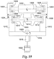
- Figure 19 depicts a simplified embodiment of the mounting system depicted in Figures 1-18 , below.
- the system of Figure 19 omits details found in Figures 1-18 , for the sake of providing a conceptual understanding of the system.
- the purpose of the discussion corresponding to Figure 19 is to generally orient the reader to certain salient features of the mounting system without immersing the reader in the details presented in the discussion relating to Figures 1-18 .
- the system includes a horn 1900 and an anvil 1902.
- a gap separates the horn 1900 from the anvil 1902.
- the anvil 1902 is mounted in a housing 1904 that is fastened to ground.
- the anvil 1902 is free to rotate about its longitudinal axis 1906, by virtue of ball bearings 1908 interposed between the anvil 1902 and the housing 1904.
- the anvil 1902 exhibits no other degrees of freedom, due to being mounted within a structure fastened to ground.
- the horn 1900 is mounted within a frame 1910.
- Ball bearings 1912 permit the horn to rotate about its longitudinal axis 1914.
- a linking member 1916 joins the two halves of the frame 1910.
- the linking member 1916 is attached to a translator 1918 by a pivot 1920.
- the frame 1910, linking member 1916, and horn 1900 may rotate about an axis defined by the pivot 1920 (the axis extends in and out of the page).
- the translator 1918 is constrained by a structure fastened to earth, so that it exhibits a single degree of freedom: it may move along a vector perpendicular to the longitudinal axis 1906 of the anvil 1902.
- the frame 1910, linking member 1916, and horn 1900 may move along the aforementioned vector.
- the horn 1900 (and frame 1910 and linking member 1916) may advance toward, or withdraw from, the anvil 1902.
- An actuator 1922 imparts a force upon the translator 1918, so as to urge the horn 1900 toward the anvil 1902.
- the length of the gap between the horn 1900 and the anvil 1902 is controlled by a pair of threaded fasteners 1924, 1926, which extend through the horn's frame 1910 and engage the housing 1904 in which the anvil 1902 is mounted.
- the frame 1910, linking member 1916, and horn 1900 are rotated about the aforementioned axis defined by the pivot 1920.
- the threaded fasteners 1924 and 1926 the longitudinal axis 1914 of the horn 1900 may be adjusted, so as to be substantially parallel to that of the anvil 1902.
- both threaded fasteners 1924 and 1926 in the same fashion, the horn 1900 may be advanced toward, or withdrawn from, the anvil 1902 without adjusting the angle of the horn 1900.
- the mounting system of Figure 19 permits only two degrees of freedom for positioning of the horn 1900.
- the horn 1900 may be advanced toward, or withdrawn from, the anvil 1902. This degree of freedom is permitted by virtue of coupling of the housing 1910 to the translator 1918, which is confined to motion in one direction.
- the longitudinal axis 1914 of the horn 1900 may be rotated about an axis perpendicular to the longitudinal axis 1906 of the anvil 1902. This degree of freedom is permitted by virtue of the pivot 1920.
- the various components of the system depicted in Figure 19 functionally correspond to components found in the system depicted in Figures 1-18 .
- the anvil 1902 corresponds to the anvil identified by reference numeral 21 in Figure 2 and 3 .
- the housing 1904 in which the anvil 1902 is mounted corresponds to the structures identified by reference numerals 24 and 25 in Figures 2 and 3 (i.e., the anvil 21 is mounted within the structures identified by reference numerals 24 and 25, thus making them analogous to the housing 1904 in Figure 19 ).
- the horn 1900 corresponds to the horn identified by reference numeral 42 in Figure 11 .
- the frame 1910 in which the horn 1900 is mounted corresponds to the structure identified by reference numeral 32 in Figure 7 .
- the linking member 1916 corresponds to the structure identified by reference numeral 31 in Figure 7 (i.e., the structure identified by reference numeral 31 joins both halves of the frame 32, thus making it analogous to the linking member 1916).
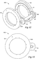
- the ball bearings 1912 upon which the horn 1900 rides correspond to the nodal mount identified by reference numerals 43, 44, and 45 in Figure 11 (i.e., the nodal mounts 43, 44, and 45 permit rotation of the horn 42, in a manner appropriate for a vibrating body.
- a vibrating body such as a horn, would damage the ball bearings if riding thereupon.
- the need for nodal mount 43, 44, and 45. would damage the ball bearings if riding thereupon. Hence, the need for nodal mount 43, 44, and 45.).
- the pivot 1920 corresponds to the pivot identified by reference numeral M12 in Figure 16A .
- the pivot M12 permits rotation of the frame 32, and therefore rotation of the horn 42.
- Translator 1918 corresponds to translation member M11, also depicted in Figure 16A .
- the frame 32 is joined to translation member M11, which is permitted one degree of freedom-it may advance toward or withdraw from the anvil 21.
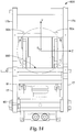
- the actuator 1922 corresponds to the air bladder identified by reference numeral 61 in Figure 14 . In other words, the air bladder 61 generates a force to urge the translator M11 toward the anvil 21.
- the threaded fasteners 1924 and 1926 correspond to the cams identified by reference numeral 50 in Figures 12 and 13 .
- the cams 50 ride upon the cam followers 27 (shown in Figure 3 ) attached to the frame 24, 25 in which the anvil 21 is mounted, and thereby alter the distance between the horn 42 and the anvil 21 and/or the orientation of the longitudinal axis of the horn 42 when rotated.
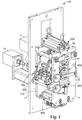
- Rotary welding module 100 includes features that limit the degrees-of-freedom of the horn in relation to the anvil, thus better controlling the gap and the movement between the horn and the anvil during the welding process.
- Module 100 includes a first sub-assembly, particularly an anvil assembly 200, a second sub-assembly, particularly a horn mount assembly 300, a third sub-assembly, particularly a horn assembly 400, a fourth sub-assembly, particularly a horn-anvil gap adjustment assembly 500, a fifth sub-assembly, particularly a horn lifting assembly 600, and a sixth sub-assembly, particularly a nip assembly 700. Additional details regarding each of these sub-assemblies are provided below. Also illustrated in Figure 1 as a part of rotary welding module 100 are side plates 17, tie rods 18, a horn servomotor 19, and an anvil servomotor and gearbox 11.
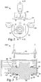
- FIGS 2 and 3 provide a detailed view of anvil assembly 200.
- Anvil assembly 200 includes an anvil roll 21 having a roll face 22 and journals 23.
- Anvil roll 21 can be any suitable roll, such as a die roll, embossing roll, printing roll, or welding rolls.
- Anvil bearing blocks 24 are mounted to anvil frame 25.
- Anvil roll 21 is mounted to bearing blocks 24 using by means of precision duplex ball bearings 26.
- Anvil roll 21 is configured to rotate around an axis, preferably an axis extending longitudinally through the center of roll 21.
- Bearing locknuts 28 hold the duplex pairs 26 together and on journals 23.
- Anvil assembly 200 also includes two cam-follower bearing assemblies 27 mounted on anvil-roll journals 23. These cam follower assemblies 27 are held onto journals 23 using bearing locknuts 29.
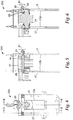
- FIG. 4 through 6 additional views of anvil roll assembly 200, supported by side plates 17, are illustrated.
- Anvil roll 21 is mounted on tie rods 18 and to side plates 17, in a manner so that roll 21 can rotate around its longitudinal axis.
- bearing blocks 24 are supported by tie rods 18.
- Anvil roll 21 is fixed to tie rods 18 by way of shaft clamps M1.
- clamps M1 are in a loosened condition, anvil roll assembly 200 can be moved in relation to side plates 17, for example by using a threaded rod 80 attached to a handle 81.
- a threaded bar 82 is fixed to the side plates 17 and bearings 83 are attached to one of bearing blocks 24.
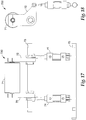
- FIG 7 shows horn mount assembly 300, which includes a mount frame 31, horn-bearing blocks 32, a horn drive motor 19, a horn drive means, such as belt 34, and horn-anvil gap adjustment assembly 500.
- Figures 8 and 9 show additional views and features of horn mount assembly 300.
- slots M2 (as shown in Figure 15 ) in side plates 17 as shown in Fig. 1 guide and allow horn mount assembly 300 to move.
- surfaces 36 on bearing blocks 32 contact surfaces M3 of side plates 17; preferably, at least a portion of bearing block 32 fits within slot M2.
- surfaces 36 are cylindrical surfaces, though this is not essential.
- Bearing blocks 32 also have a second set of surfaces 38, which also in an exemplary embodiment are cylindrical surfaces.
- the radius of these surfaces 38 is half the distance between the inside or bearing surfaces 17b of side plates 17 ( Figure 1A ).
- Surfaces 38 remove a translational degree of freedom along the Z-axis.
- the two remaining available degrees of freedom are translational movement along the Y-axis (towards and away from the anvil) and rotational movement along the X-axis.
- the combination of these two degrees-of-freedom allow the gap between horn 30 and the anvil to be adjusted independently on both sides of horn 30.
- Figures 10 and 11 shows horn assembly 400, which includes horn 42, nodal mounts 43, horn bearing rings 44, horn bearings 45, and horn drive sprocket 46.
- Horn 42 and nodal mounts 43 (which are described in U.S. Pat. No. 6,786,384, to Gopal Haregoppa, which is herein incorporated by reference in its entirety) illustrated are one of several possible designs, but are preferred for this embodiment.
- Figures 12 and 13 show horn gap or horn-anvil gap adjustment assembly 500.
- Assembly 500 includes first and second cams 50 and a drive gear 51 attached to the cams.
- the inner cylindrical surface of the cams, M6, rests on the cylindrical surfaces M5 of assembly 300 ( Fig. 7 ). Clearance between surfaces M5 and M6 allows the cams 50 to rotate about the z-axis.
- Gear shaft 53 is a non-rotating shaft that is mounted between bearing blocks 32 using holes M7 ( Fig. 7 ).
- Driving gears 52 are rotatably mounted to gear shaft 53. the driving gears 52 are rotated independently using a wrench the hex feature M8 to substantially parallel the z-axis of the anvil. Rotation of the driving gears 52 causes the cams 50 to rotate.
- cams 50 generate a rise of 0.100 inch (about 2.5 mm) over 300 degrees of cam rotation. This provides an adjustment resolution of 3/10000 inch per degree (about 0.0076 mm per degree).
- Figure 14 shows horn lift assembly 600, which is used to move, generally raise and lower, horn mount assembly 300 in relation to side plates 17. The motion of horn mounting assembly 300 is stopped when cam surface 50a contact cam followers 27 of anvil assembly 200.
- horn lift assembly 600 includes lift frame 60 fixedly attached to side plates 17. Attached to lift frame 60 is pneumatic bellows 61, which is configured to expand and decrease, as desired. In use, pressurizing bellows 61 applies force to horn mount assembly 300 to push assembly 300 towards anvil roll 21; other force generators, such as linear actuators, pneumatic cylinders and hydraulic cylinders could alternately be used. As discussed previously, horn mount assembly 300 has two remaining degrees-of-freedom. One is translational along the Y axis and one rotational along the X( ⁇ x )-axis ( Figure 14 ).
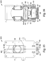
- FIGS 15 and 16 show additional views of horn lift assembly 600.
- a geared 7-bar linkage is used to control the rotation of horn mount assembly 300 in relation to side plates 17 and mount frame 31.
- This linkage includes connecting link arms 62, pivot arms 63, pivot shafts 64, gears 65, and pivot connections 66, 67.
- connecting link arms 62 raise the ends of pivot arms 63, which rotate an equal amount, due to arms 63 being geared together. If there were no clearance or slop in the pivot joints 66, 67, horn mount assembly 300 would only move vertically and the rotational degree-of-freedom ( ⁇ x) would be removed. However, by the inclusion of clearance to joints 66, 67, an amount of rotation is allowed.
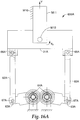
- Figure 16A and B shows the geared 7-bar linkage 600A,along with the horn mount assembly 300 in more basic kinematic form.
- link 1 is ground.
- Linkage 600A includes connecting link arms 62A, pivot arms 63A, pivot shafts 64A, and pivot connects 66A, 67A. Connecting link arms 62A raise the ends of pivot arms 63A at joint 67A, arms 63A which rotate an equal amount, due to arms 63A being geared together.
- Pivot arms 63A are two binary links that are connected to ground and to link arms 62A via joints 64A and 67A, respectively. Pivot arms 63A are also connected to each other using a gear joint. The ratio of the gear joint is 1:1.
- Link arms 62A are also binary links that are connected to pivot arms 63A and to mount frame 31A via revolute joints 67A, 66A respectively.
- Mount frame 31A is a ternary link that is connected to arms 62A and slide block M11 with pivot joints 67A and M12. Slider block M11 is connected to ground and mount frame 31A using joints M10 and M12. Slider block M11 controls the motion of mount frame 31A so that mount frame 31A has only a translational and rotational degree-of-freedom.
- Linkage 600A includes joint clearance at joints 66A by including an oversized hole. Additionally or alternatively, joint clearance could be present at pivot joints 67A. In a conventional geared-7-bar linkage mechanism without joint clearances, the motion of mount frame 31A would only be translational as pivot arms 63 A are rotated. By having the joint clearance, the horn 42 of the horn mount assembly300, which is connected to mount frame 31A, can be adjusted with limited angular motion.
- the clearance in the joint may also be accomplished using clearance controls/limits angular motion ⁇ x, with the use of a slot, as is illustrated in Figure 16B .
- linkage 600B includes connecting link arms 62B, pivot arms 63B, pivot shafts 64B, and pivot connections 66B, 67B.
- C is equal to 0.762 mm (0.03 inch) and L is 301.8 mm (11.88 inch), thus providing ⁇ as 0.3 degrees.
- the clearance either an oversized hole, a slot, or other, is selected so that the rotation allows variations in the gap between horn 42 and the anvil to adjust for manufacturing tolerances and process variations.
- the clearance is not, however, so great as to prevent or inhibit mounting of horn 42 and stopping correctly on cams 50.
- Nip assembly 700 includes nip roller 71, nip arms 72, pivot shaft 73, nip cylinders 74, and cylinder support shaft 75.
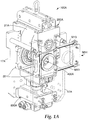
- FIG. 1A An alternate exemplary rotary welding module is illustrated in Figure 1A as apparatus 100A. Similar to apparatus 100 of Figure 1 , apparatus 100A has multiple sub-assemblies. Shown in Figure 1A are anvil assembly 200A which includes anvil roll 21A, horn assembly 400A, and horn lifting assembly 600A. Also shown in Figure 1A are side plates 17A. An alternate method of limiting the horn assembly to two degrees of freedom uses leaf springs M13 and M14. Apparatus 100A includes leaf springs M13, typically at least two pairs of leaf springs M14. Each pair of leaf springs M14 is attached to different bearing blocks 32 and different side plates 17A.
- a welding apparatus based on reducing the degrees-of-freedom available to better control the gap between the anvil and the horn, generally includes anvil roll 21 or other rotatable tool roll having an first axis, and a mounting system for supporting anvil roll 21 so that it can rotate about its first axis.
- the mounting system is configured such that anvil roll 21 has only two additional degrees of freedom, the first additional degree of freedom being translational motion in a direction perpendicular to the first axis, and the second additional degree of freedom being rotational motion about a second axis that is both perpendicular to the first axis and the direction of the first additional degree of freedom. This limited range of movement stabilizes the distance between the anvil and the horn.
- gap control for a system can be achieved by measuring the operating frequency of the horn, and then adjusting the force, for example, pressure, that controls the gap.
- the specific equations can be derived or determined empirically for any horn geometry, including linear and rotary horns.
Landscapes
- Engineering & Computer Science (AREA)
- Mechanical Engineering (AREA)
- Physics & Mathematics (AREA)
- Fluid Mechanics (AREA)
- Lining Or Joining Of Plastics Or The Like (AREA)
- Pressure Welding/Diffusion-Bonding (AREA)
Applications Claiming Priority (2)
| Application Number | Priority Date | Filing Date | Title |
|---|---|---|---|
| US64097905P | 2005-01-03 | 2005-01-03 | |
| PCT/US2005/047347 WO2006074031A1 (en) | 2005-01-03 | 2005-12-29 | Method and apparatus for controlling the gap between the horn and the anvil of an ultrasonic welding system |
Publications (2)
| Publication Number | Publication Date |
|---|---|
| EP1833659A1 EP1833659A1 (en) | 2007-09-19 |
| EP1833659B1 true EP1833659B1 (en) | 2017-09-20 |
Family
ID=36218610
Family Applications (1)
| Application Number | Title | Priority Date | Filing Date |
|---|---|---|---|
| EP05855841.2A Active EP1833659B1 (en) | 2005-01-03 | 2005-12-29 | Method and apparatus for controlling the gap between the horn and the anvil of an ultrasonic welding system |
Country Status (10)
| Country | Link |
|---|---|
| US (1) | US7690548B2 (ar) |
| EP (1) | EP1833659B1 (ar) |
| JP (1) | JP2008526514A (ar) |
| KR (1) | KR101197995B1 (ar) |
| CN (1) | CN100586703C (ar) |
| AR (1) | AR053535A1 (ar) |
| BR (1) | BRPI0518538B1 (ar) |
| MX (1) | MX2007007979A (ar) |
| TW (1) | TWI436880B (ar) |
| WO (1) | WO2006074031A1 (ar) |
Families Citing this family (32)
| Publication number | Priority date | Publication date | Assignee | Title |
|---|---|---|---|---|
| PL1854618T3 (pl) | 2006-05-11 | 2013-05-31 | Indag Gesellschaft Fuer Ind Mbh & Co Betriebs Kg | Urządzenie do zgrzewania ultradźwiękowego |
| ATE485155T1 (de) * | 2008-04-18 | 2010-11-15 | Cavanna Spa | Vorrichtung zur unterstützung von gegenlaufelementen |
| DE102009002296A1 (de) * | 2009-04-09 | 2010-10-14 | Robert Bosch Gmbh | Vorrichtung und Verfahren zum Bearbeiten eines Packstoffs mittels Ultraschall |
| DE102009002298A1 (de) * | 2009-04-09 | 2010-10-14 | Robert Bosch Gmbh | Vorrichtung zum Bearbeiten eines Packstoffs mittels Ultraschall |
| DE102009002295A1 (de) | 2009-04-09 | 2010-10-14 | Robert Bosch Gmbh | Vorrichtung zum Bearbeiten eines Packstoffs mittels Ultraschall |
| US8945457B2 (en) | 2009-04-27 | 2015-02-03 | Sca Hygiene Products Ab | Method and system for creating an apertured web-shaped material |
| US9005799B2 (en) | 2010-08-25 | 2015-04-14 | Lg Chem, Ltd. | Battery module and methods for bonding cell terminals of battery cells together |
| DE102010043089A1 (de) * | 2010-10-29 | 2012-05-03 | Robert Bosch Gmbh | Siegelbacke zur Siegelung eines Packstoffs mittels Ultraschall |
| US9034129B2 (en) | 2011-01-13 | 2015-05-19 | Lg Chem, Ltd. | Ultrasonic welding system and method for forming a weld joint utilizing the ultrasonic welding system |
| US8821149B2 (en) * | 2011-05-05 | 2014-09-02 | Kimberly-Clark Worldwide, Inc. | Web treatment apparatus having center bearer ring |
| US8640760B2 (en) * | 2011-08-19 | 2014-02-04 | Lg Chem, Ltd. | Ultrasonic welding machine and method of aligning an ultrasonic welding horn relative to an anvil |
| US8695867B2 (en) | 2011-08-31 | 2014-04-15 | Lg Chem, Ltd. | Ultrasonic welding machine and method of assembling the ultrasonic welding machine |
| ITTO20130524A1 (it) * | 2013-06-26 | 2014-12-27 | Soremartec Sa | Gruppo di posaggio |
| CN104148798B (zh) * | 2014-09-04 | 2016-05-04 | 芜湖新宝超声波设备有限公司 | 汽车仪表盘超声波焊接机 |
| CN107073639B (zh) * | 2014-10-15 | 2019-08-23 | 远景Aesc日本有限公司 | 超声波接合装置和超声波接合方法 |
| US10259165B2 (en) | 2015-04-01 | 2019-04-16 | Aurizon Ultrasonics, LLC | Apparatus for fabricating an elastic nonwoven material |
| DE102015110387A1 (de) * | 2015-06-29 | 2016-12-29 | Sig Technology Ag | Vorrichtung zur Bearbeitung, insbesondere zur Ultraschallverschweißung, von Packungsmänteln |
| EP3368294B1 (en) * | 2015-10-29 | 2021-05-12 | Kimberly-Clark Worldwide, Inc. | Ultrasonic anvil having low transmissibility |
| US10537479B2 (en) | 2016-09-15 | 2020-01-21 | Curt G. Joa, Inc. | Dual bonder |
| CN106298685B (zh) * | 2016-09-29 | 2019-01-04 | 中国船舶重工集团公司第七一九研究所 | 一种采用超声波焊接的电子芯片封装结构 |
| JP7050768B2 (ja) | 2016-09-30 | 2022-04-08 | デューケイン アイエーエス エルエルシー | 弾性不織材料を製造するための装置 |
| EP3672796A4 (en) | 2017-08-25 | 2021-05-26 | 3M Innovative Properties Company | ADHESIVE ARTICLES ALLOWING REMOVAL WITHOUT DAMAGE |
| US11517977B2 (en) * | 2017-09-15 | 2022-12-06 | Tech-Sonic, Inc. | Dual cam servo weld splicer |
| US11426992B2 (en) | 2018-10-04 | 2022-08-30 | Curt G. Joa, Inc. | Closed-loop adjustment system and method for gap control and leveling of ultrasonic devices |
| EP3941738A4 (en) | 2019-03-22 | 2023-06-14 | Dukane IAS, LLC | DEVICE FOR PRODUCTION OF AN ELASTIC NON-WOVEN FABRIC |
| CN109848541B (zh) * | 2019-03-27 | 2024-02-09 | 晋江海纳机械有限公司 | 一种连续式超声波焊接机 |
| WO2021212130A1 (en) * | 2020-04-17 | 2021-10-21 | Curt G. Joa, Inc. | Closed-loop multi-axis adjustment system and method for gap control and leveling of ultrasonic devices |
| US11311960B2 (en) * | 2020-08-10 | 2022-04-26 | Fabrisonic Llc | High-efficiency welding assembly for use in ultrasonic additive manufacturing |
| CN114643715A (zh) * | 2020-12-17 | 2022-06-21 | 沈阳新松机器人自动化股份有限公司 | 一种口罩机封边焊齿机构 |
| CN114799468A (zh) * | 2021-01-28 | 2022-07-29 | 无锡鼎加弘思饮品科技有限公司 | 一种超声波焊接装置及超声波焊接测试设备 |
| CN115958332B (zh) * | 2021-10-13 | 2024-06-04 | 宁德时代新能源科技股份有限公司 | 一种焊接设备 |
| CN115740725B (zh) * | 2022-12-28 | 2023-09-15 | 苏州泽术智能自动化科技有限公司 | 一种用于焊头安装全自动焊头夹紧装置 |
Family Cites Families (17)
| Publication number | Priority date | Publication date | Assignee | Title |
|---|---|---|---|---|
| US4553461A (en) * | 1982-10-12 | 1985-11-19 | Magna-Graphics Corporation | Rotary web processing apparatus |
| DE3501631C2 (de) * | 1985-01-19 | 1987-05-14 | VEGLA Vereinigte Glaswerke GmbH, 5100 Aachen | Vorrichtung zum Zusammenwalzen von Glasscheiben mit einer Kunststoffolie |
| JP2705423B2 (ja) * | 1992-01-24 | 1998-01-28 | 株式会社日立製作所 | 超音波接合装置及び品質モニタリング方法 |
| US5552013A (en) * | 1994-06-29 | 1996-09-03 | Kimberly-Clark Corporation | Apparatus and method for rotary bonding |
| JP2837126B2 (ja) * | 1996-01-23 | 1998-12-14 | 三菱重工業株式会社 | シングルフェーサの糊付調整方法及び装置 |
| PT907509E (pt) * | 1996-05-29 | 2001-11-30 | Alusuisse Tech & Man Ag | Mecanismo de laminacao para produzir um composito laminado |
| DE19803638A1 (de) * | 1998-02-02 | 1999-08-05 | Kuesters Eduard Maschf | Vorrichtung zum Bearbeiten einer Materialbahn mit Ultraschall |
| JP3600431B2 (ja) | 1998-03-09 | 2004-12-15 | 三島 大二 | 超音波溶接装置 |
| JP3290632B2 (ja) * | 1999-01-06 | 2002-06-10 | 株式会社アルテクス | 超音波振動接合装置 |
| US6287403B1 (en) * | 2000-02-15 | 2001-09-11 | Kimberly-Clark Worldwide, Inc. | Support system for rotary function rolls |
| US6540854B2 (en) * | 2000-11-30 | 2003-04-01 | Kimberly-Clark Worldwide, Inc. | Load cell closed loop control for rotary ultrasonic bonding apparatus |
| JP3597476B2 (ja) | 2001-01-16 | 2004-12-08 | 三島 大二 | 超音波溶接装置における超音波振動ホーン |
| US6634539B2 (en) * | 2001-09-21 | 2003-10-21 | 3M Innovative Properties Company | Adjustable-gap rotary ultrasonic horn mounting apparatus and method for mounting |
| US7998528B2 (en) * | 2002-02-14 | 2011-08-16 | Massachusetts Institute Of Technology | Method for direct fabrication of nanostructures |
| EP1447204A1 (de) * | 2003-02-12 | 2004-08-18 | Telsonic Holding AG | Vorrichtung und Verfahren zum Bearbeiten von Bauteilen |
| JP4297715B2 (ja) * | 2003-03-31 | 2009-07-15 | ユニ・チャーム株式会社 | シール装置および前記シール装置を用いたシール方法 |
| US6786384B1 (en) * | 2003-06-13 | 2004-09-07 | 3M Innovative Properties Company | Ultrasonic horn mount |
-
2005
- 2005-12-29 BR BRPI0518538A patent/BRPI0518538B1/pt not_active IP Right Cessation
- 2005-12-29 EP EP05855841.2A patent/EP1833659B1/en active Active
- 2005-12-29 MX MX2007007979A patent/MX2007007979A/es not_active Application Discontinuation
- 2005-12-29 WO PCT/US2005/047347 patent/WO2006074031A1/en active Application Filing
- 2005-12-29 US US11/321,265 patent/US7690548B2/en active Active
- 2005-12-29 CN CN200580045835A patent/CN100586703C/zh active Active
- 2005-12-29 JP JP2007549610A patent/JP2008526514A/ja not_active Withdrawn
- 2005-12-29 KR KR1020077017857A patent/KR101197995B1/ko active IP Right Grant
-
2006
- 2006-01-02 TW TW095100123A patent/TWI436880B/zh not_active IP Right Cessation
- 2006-01-03 AR ARP060100009A patent/AR053535A1/es not_active Application Discontinuation
Non-Patent Citations (1)
| Title |
|---|
| None * |
Also Published As
| Publication number | Publication date |
|---|---|
| JP2008526514A (ja) | 2008-07-24 |
| KR20070104904A (ko) | 2007-10-29 |
| US7690548B2 (en) | 2010-04-06 |
| US20060144904A1 (en) | 2006-07-06 |
| CN100586703C (zh) | 2010-02-03 |
| TWI436880B (zh) | 2014-05-11 |
| MX2007007979A (es) | 2007-08-22 |
| AR053535A1 (es) | 2007-05-09 |
| TW200639043A (en) | 2006-11-16 |
| WO2006074031A1 (en) | 2006-07-13 |
| KR101197995B1 (ko) | 2012-11-05 |
| EP1833659A1 (en) | 2007-09-19 |
| CN101094761A (zh) | 2007-12-26 |
| BRPI0518538B1 (pt) | 2016-12-20 |
| BRPI0518538A2 (pt) | 2008-12-02 |
Similar Documents
| Publication | Publication Date | Title |
|---|---|---|
| EP1833659B1 (en) | Method and apparatus for controlling the gap between the horn and the anvil of an ultrasonic welding system | |
| US6547903B1 (en) | Rotary ultrasonic bonder or processor capable of high speed intermittent processing | |
| EP1455956B1 (en) | Control of processing force and process gap in rigid rotary ultrasonic systems | |
| CA2148641C (en) | Rotary sealing system | |
| US5421924A (en) | Apparatus and method for ultrasonic sealing disposable diapers | |
| US6287403B1 (en) | Support system for rotary function rolls | |
| JP2008526514A5 (ar) | ||
| WO2006074116A1 (en) | An elastic laminate material, and method of making | |
| EP1432545B1 (en) | Rotary ultrasonic horn mounting apparatus and method for mounting | |
| EP1455984B1 (en) | Nip adjustment for a rigid ultrasonic bonding apparatus and method | |
| JP2002355270A (ja) | シール装置およびシール部を有する軟質物品の製造方法 | |
| US6517650B2 (en) | Ultrasonic bonding apparatus and methods | |
| KR20040105828A (ko) | 라미네이팅 롤의 간격 조절기 | |
| WO2017131725A1 (en) | Ultrasonic sealer | |
| AU715601B2 (en) | Rotary sealing system |
Legal Events
| Date | Code | Title | Description |
|---|---|---|---|
| PUAI | Public reference made under article 153(3) epc to a published international application that has entered the european phase |
Free format text: ORIGINAL CODE: 0009012 |
|
| 17P | Request for examination filed |
Effective date: 20070704 |
|
| AK | Designated contracting states |
Kind code of ref document: A1 Designated state(s): AT BE BG CH CY CZ DE DK EE ES FI FR GB GR HU IE IS IT LI LT LU LV MC NL PL PT RO SE SI SK TR |
|
| DAX | Request for extension of the european patent (deleted) | ||
| 17Q | First examination report despatched |
Effective date: 20081008 |
|
| STAA | Information on the status of an ep patent application or granted ep patent |
Free format text: STATUS: EXAMINATION IS IN PROGRESS |
|
| GRAP | Despatch of communication of intention to grant a patent |
Free format text: ORIGINAL CODE: EPIDOSNIGR1 |
|
| STAA | Information on the status of an ep patent application or granted ep patent |
Free format text: STATUS: GRANT OF PATENT IS INTENDED |
|
| INTG | Intention to grant announced |
Effective date: 20170329 |
|
| RIN1 | Information on inventor provided before grant (corrected) |
Inventor name: FETTIG, PAUL, M. Inventor name: POCHARDT, DONALD, L. Inventor name: MLINAR, JOHN, R. Inventor name: NAYAR, SATINDER K. Inventor name: OBLAK, DONALD, S. |
|
| GRAS | Grant fee paid |
Free format text: ORIGINAL CODE: EPIDOSNIGR3 |
|
| GRAA | (expected) grant |
Free format text: ORIGINAL CODE: 0009210 |
|
| STAA | Information on the status of an ep patent application or granted ep patent |
Free format text: STATUS: THE PATENT HAS BEEN GRANTED |
|
| AK | Designated contracting states |
Kind code of ref document: B1 Designated state(s): AT BE BG CH CY CZ DE DK EE ES FI FR GB GR HU IE IS IT LI LT LU LV MC NL PL PT RO SE SI SK TR |
|
| REG | Reference to a national code |
Ref country code: GB Ref legal event code: FG4D |
|
| REG | Reference to a national code |
Ref country code: CH Ref legal event code: EP |
|
| REG | Reference to a national code |
Ref country code: AT Ref legal event code: REF Ref document number: 929816 Country of ref document: AT Kind code of ref document: T Effective date: 20171015 |
|
| REG | Reference to a national code |
Ref country code: IE Ref legal event code: FG4D |
|
| REG | Reference to a national code |
Ref country code: DE Ref legal event code: R096 Ref document number: 602005052772 Country of ref document: DE |
|
| REG | Reference to a national code |
Ref country code: NL Ref legal event code: MP Effective date: 20170920 |
|
| PG25 | Lapsed in a contracting state [announced via postgrant information from national office to epo] |
Ref country code: FI Free format text: LAPSE BECAUSE OF FAILURE TO SUBMIT A TRANSLATION OF THE DESCRIPTION OR TO PAY THE FEE WITHIN THE PRESCRIBED TIME-LIMIT Effective date: 20170920 Ref country code: LT Free format text: LAPSE BECAUSE OF FAILURE TO SUBMIT A TRANSLATION OF THE DESCRIPTION OR TO PAY THE FEE WITHIN THE PRESCRIBED TIME-LIMIT Effective date: 20170920 Ref country code: SE Free format text: LAPSE BECAUSE OF FAILURE TO SUBMIT A TRANSLATION OF THE DESCRIPTION OR TO PAY THE FEE WITHIN THE PRESCRIBED TIME-LIMIT Effective date: 20170920 |
|
| REG | Reference to a national code |
Ref country code: LT Ref legal event code: MG4D |
|
| REG | Reference to a national code |
Ref country code: AT Ref legal event code: MK05 Ref document number: 929816 Country of ref document: AT Kind code of ref document: T Effective date: 20170920 |
|
| PG25 | Lapsed in a contracting state [announced via postgrant information from national office to epo] |
Ref country code: GR Free format text: LAPSE BECAUSE OF FAILURE TO SUBMIT A TRANSLATION OF THE DESCRIPTION OR TO PAY THE FEE WITHIN THE PRESCRIBED TIME-LIMIT Effective date: 20171221 Ref country code: BG Free format text: LAPSE BECAUSE OF FAILURE TO SUBMIT A TRANSLATION OF THE DESCRIPTION OR TO PAY THE FEE WITHIN THE PRESCRIBED TIME-LIMIT Effective date: 20171220 Ref country code: LV Free format text: LAPSE BECAUSE OF FAILURE TO SUBMIT A TRANSLATION OF THE DESCRIPTION OR TO PAY THE FEE WITHIN THE PRESCRIBED TIME-LIMIT Effective date: 20170920 |
|
| PG25 | Lapsed in a contracting state [announced via postgrant information from national office to epo] |
Ref country code: NL Free format text: LAPSE BECAUSE OF FAILURE TO SUBMIT A TRANSLATION OF THE DESCRIPTION OR TO PAY THE FEE WITHIN THE PRESCRIBED TIME-LIMIT Effective date: 20170920 |
|
| PG25 | Lapsed in a contracting state [announced via postgrant information from national office to epo] |
Ref country code: ES Free format text: LAPSE BECAUSE OF FAILURE TO SUBMIT A TRANSLATION OF THE DESCRIPTION OR TO PAY THE FEE WITHIN THE PRESCRIBED TIME-LIMIT Effective date: 20170920 Ref country code: CZ Free format text: LAPSE BECAUSE OF FAILURE TO SUBMIT A TRANSLATION OF THE DESCRIPTION OR TO PAY THE FEE WITHIN THE PRESCRIBED TIME-LIMIT Effective date: 20170920 Ref country code: PL Free format text: LAPSE BECAUSE OF FAILURE TO SUBMIT A TRANSLATION OF THE DESCRIPTION OR TO PAY THE FEE WITHIN THE PRESCRIBED TIME-LIMIT Effective date: 20170920 Ref country code: RO Free format text: LAPSE BECAUSE OF FAILURE TO SUBMIT A TRANSLATION OF THE DESCRIPTION OR TO PAY THE FEE WITHIN THE PRESCRIBED TIME-LIMIT Effective date: 20170920 |
|
| PG25 | Lapsed in a contracting state [announced via postgrant information from national office to epo] |
Ref country code: SK Free format text: LAPSE BECAUSE OF FAILURE TO SUBMIT A TRANSLATION OF THE DESCRIPTION OR TO PAY THE FEE WITHIN THE PRESCRIBED TIME-LIMIT Effective date: 20170920 Ref country code: EE Free format text: LAPSE BECAUSE OF FAILURE TO SUBMIT A TRANSLATION OF THE DESCRIPTION OR TO PAY THE FEE WITHIN THE PRESCRIBED TIME-LIMIT Effective date: 20170920 Ref country code: IT Free format text: LAPSE BECAUSE OF FAILURE TO SUBMIT A TRANSLATION OF THE DESCRIPTION OR TO PAY THE FEE WITHIN THE PRESCRIBED TIME-LIMIT Effective date: 20170920 Ref country code: IS Free format text: LAPSE BECAUSE OF FAILURE TO SUBMIT A TRANSLATION OF THE DESCRIPTION OR TO PAY THE FEE WITHIN THE PRESCRIBED TIME-LIMIT Effective date: 20180120 Ref country code: AT Free format text: LAPSE BECAUSE OF FAILURE TO SUBMIT A TRANSLATION OF THE DESCRIPTION OR TO PAY THE FEE WITHIN THE PRESCRIBED TIME-LIMIT Effective date: 20170920 |
|
| REG | Reference to a national code |
Ref country code: DE Ref legal event code: R097 Ref document number: 602005052772 Country of ref document: DE |
|
| PLBE | No opposition filed within time limit |
Free format text: ORIGINAL CODE: 0009261 |
|
| STAA | Information on the status of an ep patent application or granted ep patent |
Free format text: STATUS: NO OPPOSITION FILED WITHIN TIME LIMIT |
|
| PG25 | Lapsed in a contracting state [announced via postgrant information from national office to epo] |
Ref country code: DK Free format text: LAPSE BECAUSE OF FAILURE TO SUBMIT A TRANSLATION OF THE DESCRIPTION OR TO PAY THE FEE WITHIN THE PRESCRIBED TIME-LIMIT Effective date: 20170920 |
|
| REG | Reference to a national code |
Ref country code: CH Ref legal event code: PL |
|
| 26N | No opposition filed |
Effective date: 20180621 |
|
| REG | Reference to a national code |
Ref country code: IE Ref legal event code: MM4A |
|
| PG25 | Lapsed in a contracting state [announced via postgrant information from national office to epo] |
Ref country code: LU Free format text: LAPSE BECAUSE OF NON-PAYMENT OF DUE FEES Effective date: 20171229 |
|
| REG | Reference to a national code |
Ref country code: FR Ref legal event code: ST Effective date: 20180831 |
|
| REG | Reference to a national code |
Ref country code: BE Ref legal event code: MM Effective date: 20171231 |
|
| PG25 | Lapsed in a contracting state [announced via postgrant information from national office to epo] |
Ref country code: FR Free format text: LAPSE BECAUSE OF NON-PAYMENT OF DUE FEES Effective date: 20180102 Ref country code: IE Free format text: LAPSE BECAUSE OF NON-PAYMENT OF DUE FEES Effective date: 20171229 |
|
| PG25 | Lapsed in a contracting state [announced via postgrant information from national office to epo] |
Ref country code: LI Free format text: LAPSE BECAUSE OF NON-PAYMENT OF DUE FEES Effective date: 20171231 Ref country code: SI Free format text: LAPSE BECAUSE OF FAILURE TO SUBMIT A TRANSLATION OF THE DESCRIPTION OR TO PAY THE FEE WITHIN THE PRESCRIBED TIME-LIMIT Effective date: 20170920 Ref country code: BE Free format text: LAPSE BECAUSE OF NON-PAYMENT OF DUE FEES Effective date: 20171231 Ref country code: CH Free format text: LAPSE BECAUSE OF NON-PAYMENT OF DUE FEES Effective date: 20171231 |
|
| PGFP | Annual fee paid to national office [announced via postgrant information from national office to epo] |
Ref country code: DE Payment date: 20181218 Year of fee payment: 14 |
|
| PG25 | Lapsed in a contracting state [announced via postgrant information from national office to epo] |
Ref country code: HU Free format text: LAPSE BECAUSE OF FAILURE TO SUBMIT A TRANSLATION OF THE DESCRIPTION OR TO PAY THE FEE WITHIN THE PRESCRIBED TIME-LIMIT; INVALID AB INITIO Effective date: 20051229 Ref country code: MC Free format text: LAPSE BECAUSE OF FAILURE TO SUBMIT A TRANSLATION OF THE DESCRIPTION OR TO PAY THE FEE WITHIN THE PRESCRIBED TIME-LIMIT Effective date: 20170920 |
|
| PG25 | Lapsed in a contracting state [announced via postgrant information from national office to epo] |
Ref country code: CY Free format text: LAPSE BECAUSE OF NON-PAYMENT OF DUE FEES Effective date: 20170920 |
|
| PG25 | Lapsed in a contracting state [announced via postgrant information from national office to epo] |
Ref country code: TR Free format text: LAPSE BECAUSE OF FAILURE TO SUBMIT A TRANSLATION OF THE DESCRIPTION OR TO PAY THE FEE WITHIN THE PRESCRIBED TIME-LIMIT Effective date: 20170920 |
|
| PG25 | Lapsed in a contracting state [announced via postgrant information from national office to epo] |
Ref country code: PT Free format text: LAPSE BECAUSE OF FAILURE TO SUBMIT A TRANSLATION OF THE DESCRIPTION OR TO PAY THE FEE WITHIN THE PRESCRIBED TIME-LIMIT Effective date: 20170920 |
|
| REG | Reference to a national code |
Ref country code: DE Ref legal event code: R119 Ref document number: 602005052772 Country of ref document: DE |
|
| PG25 | Lapsed in a contracting state [announced via postgrant information from national office to epo] |
Ref country code: DE Free format text: LAPSE BECAUSE OF NON-PAYMENT OF DUE FEES Effective date: 20200701 |
|
| PGFP | Annual fee paid to national office [announced via postgrant information from national office to epo] |
Ref country code: GB Payment date: 20231124 Year of fee payment: 19 |