EP1832872A1 - Plate for biological sample analysis - Google Patents
Plate for biological sample analysis Download PDFInfo
- Publication number
- EP1832872A1 EP1832872A1 EP05814150A EP05814150A EP1832872A1 EP 1832872 A1 EP1832872 A1 EP 1832872A1 EP 05814150 A EP05814150 A EP 05814150A EP 05814150 A EP05814150 A EP 05814150A EP 1832872 A1 EP1832872 A1 EP 1832872A1
- Authority
- EP
- European Patent Office
- Prior art keywords
- biological sample
- chamber
- analysis plate
- sample
- microchannel
- Prior art date
- Legal status (The legal status is an assumption and is not a legal conclusion. Google has not performed a legal analysis and makes no representation as to the accuracy of the status listed.)
- Withdrawn
Links
Images



Classifications
-
- G—PHYSICS
- G01—MEASURING; TESTING
- G01N—INVESTIGATING OR ANALYSING MATERIALS BY DETERMINING THEIR CHEMICAL OR PHYSICAL PROPERTIES
- G01N35/00—Automatic analysis not limited to methods or materials provided for in any single one of groups G01N1/00 - G01N33/00; Handling materials therefor
- G01N35/08—Automatic analysis not limited to methods or materials provided for in any single one of groups G01N1/00 - G01N33/00; Handling materials therefor using a stream of discrete samples flowing along a tube system, e.g. flow injection analysis
-
- B—PERFORMING OPERATIONS; TRANSPORTING
- B01—PHYSICAL OR CHEMICAL PROCESSES OR APPARATUS IN GENERAL
- B01L—CHEMICAL OR PHYSICAL LABORATORY APPARATUS FOR GENERAL USE
- B01L3/00—Containers or dishes for laboratory use, e.g. laboratory glassware; Droppers
- B01L3/50—Containers for the purpose of retaining a material to be analysed, e.g. test tubes
- B01L3/502—Containers for the purpose of retaining a material to be analysed, e.g. test tubes with fluid transport, e.g. in multi-compartment structures
- B01L3/5027—Containers for the purpose of retaining a material to be analysed, e.g. test tubes with fluid transport, e.g. in multi-compartment structures by integrated microfluidic structures, i.e. dimensions of channels and chambers are such that surface tension forces are important, e.g. lab-on-a-chip
- B01L3/50273—Containers for the purpose of retaining a material to be analysed, e.g. test tubes with fluid transport, e.g. in multi-compartment structures by integrated microfluidic structures, i.e. dimensions of channels and chambers are such that surface tension forces are important, e.g. lab-on-a-chip characterised by the means or forces applied to move the fluids
-
- G—PHYSICS
- G01—MEASURING; TESTING
- G01N—INVESTIGATING OR ANALYSING MATERIALS BY DETERMINING THEIR CHEMICAL OR PHYSICAL PROPERTIES
- G01N15/00—Investigating characteristics of particles; Investigating permeability, pore-volume or surface-area of porous materials
- G01N15/10—Investigating individual particles
- G01N15/14—Optical investigation techniques, e.g. flow cytometry
- G01N15/1429—Signal processing
- G01N15/1433—Signal processing using image recognition
-
- G—PHYSICS
- G01—MEASURING; TESTING
- G01N—INVESTIGATING OR ANALYSING MATERIALS BY DETERMINING THEIR CHEMICAL OR PHYSICAL PROPERTIES
- G01N35/00—Automatic analysis not limited to methods or materials provided for in any single one of groups G01N1/00 - G01N33/00; Handling materials therefor
- G01N35/00029—Automatic analysis not limited to methods or materials provided for in any single one of groups G01N1/00 - G01N33/00; Handling materials therefor provided with flat sample substrates, e.g. slides
-
- B—PERFORMING OPERATIONS; TRANSPORTING
- B01—PHYSICAL OR CHEMICAL PROCESSES OR APPARATUS IN GENERAL
- B01L—CHEMICAL OR PHYSICAL LABORATORY APPARATUS FOR GENERAL USE
- B01L2200/00—Solutions for specific problems relating to chemical or physical laboratory apparatus
- B01L2200/06—Fluid handling related problems
- B01L2200/0605—Metering of fluids
-
- B—PERFORMING OPERATIONS; TRANSPORTING
- B01—PHYSICAL OR CHEMICAL PROCESSES OR APPARATUS IN GENERAL
- B01L—CHEMICAL OR PHYSICAL LABORATORY APPARATUS FOR GENERAL USE
- B01L2200/00—Solutions for specific problems relating to chemical or physical laboratory apparatus
- B01L2200/06—Fluid handling related problems
- B01L2200/0621—Control of the sequence of chambers filled or emptied
-
- B—PERFORMING OPERATIONS; TRANSPORTING
- B01—PHYSICAL OR CHEMICAL PROCESSES OR APPARATUS IN GENERAL
- B01L—CHEMICAL OR PHYSICAL LABORATORY APPARATUS FOR GENERAL USE
- B01L2200/00—Solutions for specific problems relating to chemical or physical laboratory apparatus
- B01L2200/06—Fluid handling related problems
- B01L2200/0689—Sealing
-
- B—PERFORMING OPERATIONS; TRANSPORTING
- B01—PHYSICAL OR CHEMICAL PROCESSES OR APPARATUS IN GENERAL
- B01L—CHEMICAL OR PHYSICAL LABORATORY APPARATUS FOR GENERAL USE
- B01L2300/00—Additional constructional details
- B01L2300/06—Auxiliary integrated devices, integrated components
- B01L2300/0627—Sensor or part of a sensor is integrated
- B01L2300/0645—Electrodes
-
- B—PERFORMING OPERATIONS; TRANSPORTING
- B01—PHYSICAL OR CHEMICAL PROCESSES OR APPARATUS IN GENERAL
- B01L—CHEMICAL OR PHYSICAL LABORATORY APPARATUS FOR GENERAL USE
- B01L2300/00—Additional constructional details
- B01L2300/06—Auxiliary integrated devices, integrated components
- B01L2300/0627—Sensor or part of a sensor is integrated
- B01L2300/0654—Lenses; Optical fibres
-
- B—PERFORMING OPERATIONS; TRANSPORTING
- B01—PHYSICAL OR CHEMICAL PROCESSES OR APPARATUS IN GENERAL
- B01L—CHEMICAL OR PHYSICAL LABORATORY APPARATUS FOR GENERAL USE
- B01L2300/00—Additional constructional details
- B01L2300/08—Geometry, shape and general structure
- B01L2300/0803—Disc shape
-
- B—PERFORMING OPERATIONS; TRANSPORTING
- B01—PHYSICAL OR CHEMICAL PROCESSES OR APPARATUS IN GENERAL
- B01L—CHEMICAL OR PHYSICAL LABORATORY APPARATUS FOR GENERAL USE
- B01L2300/00—Additional constructional details
- B01L2300/08—Geometry, shape and general structure
- B01L2300/0861—Configuration of multiple channels and/or chambers in a single devices
- B01L2300/0867—Multiple inlets and one sample wells, e.g. mixing, dilution
-
- B—PERFORMING OPERATIONS; TRANSPORTING
- B01—PHYSICAL OR CHEMICAL PROCESSES OR APPARATUS IN GENERAL
- B01L—CHEMICAL OR PHYSICAL LABORATORY APPARATUS FOR GENERAL USE
- B01L2400/00—Moving or stopping fluids
- B01L2400/04—Moving fluids with specific forces or mechanical means
- B01L2400/0403—Moving fluids with specific forces or mechanical means specific forces
- B01L2400/0409—Moving fluids with specific forces or mechanical means specific forces centrifugal forces
-
- B—PERFORMING OPERATIONS; TRANSPORTING
- B01—PHYSICAL OR CHEMICAL PROCESSES OR APPARATUS IN GENERAL
- B01L—CHEMICAL OR PHYSICAL LABORATORY APPARATUS FOR GENERAL USE
- B01L2400/00—Moving or stopping fluids
- B01L2400/04—Moving fluids with specific forces or mechanical means
- B01L2400/0403—Moving fluids with specific forces or mechanical means specific forces
- B01L2400/0415—Moving fluids with specific forces or mechanical means specific forces electrical forces, e.g. electrokinetic
- B01L2400/0421—Moving fluids with specific forces or mechanical means specific forces electrical forces, e.g. electrokinetic electrophoretic flow
-
- B—PERFORMING OPERATIONS; TRANSPORTING
- B01—PHYSICAL OR CHEMICAL PROCESSES OR APPARATUS IN GENERAL
- B01L—CHEMICAL OR PHYSICAL LABORATORY APPARATUS FOR GENERAL USE
- B01L2400/00—Moving or stopping fluids
- B01L2400/04—Moving fluids with specific forces or mechanical means
- B01L2400/0475—Moving fluids with specific forces or mechanical means specific mechanical means and fluid pressure
- B01L2400/0487—Moving fluids with specific forces or mechanical means specific mechanical means and fluid pressure fluid pressure, pneumatics
-
- B—PERFORMING OPERATIONS; TRANSPORTING
- B01—PHYSICAL OR CHEMICAL PROCESSES OR APPARATUS IN GENERAL
- B01L—CHEMICAL OR PHYSICAL LABORATORY APPARATUS FOR GENERAL USE
- B01L3/00—Containers or dishes for laboratory use, e.g. laboratory glassware; Droppers
- B01L3/50—Containers for the purpose of retaining a material to be analysed, e.g. test tubes
- B01L3/502—Containers for the purpose of retaining a material to be analysed, e.g. test tubes with fluid transport, e.g. in multi-compartment structures
- B01L3/5025—Containers for the purpose of retaining a material to be analysed, e.g. test tubes with fluid transport, e.g. in multi-compartment structures for parallel transport of multiple samples
-
- B—PERFORMING OPERATIONS; TRANSPORTING
- B01—PHYSICAL OR CHEMICAL PROCESSES OR APPARATUS IN GENERAL
- B01L—CHEMICAL OR PHYSICAL LABORATORY APPARATUS FOR GENERAL USE
- B01L3/00—Containers or dishes for laboratory use, e.g. laboratory glassware; Droppers
- B01L3/50—Containers for the purpose of retaining a material to be analysed, e.g. test tubes
- B01L3/502—Containers for the purpose of retaining a material to be analysed, e.g. test tubes with fluid transport, e.g. in multi-compartment structures
- B01L3/5027—Containers for the purpose of retaining a material to be analysed, e.g. test tubes with fluid transport, e.g. in multi-compartment structures by integrated microfluidic structures, i.e. dimensions of channels and chambers are such that surface tension forces are important, e.g. lab-on-a-chip
- B01L3/502707—Containers for the purpose of retaining a material to be analysed, e.g. test tubes with fluid transport, e.g. in multi-compartment structures by integrated microfluidic structures, i.e. dimensions of channels and chambers are such that surface tension forces are important, e.g. lab-on-a-chip characterised by the manufacture of the container or its components
-
- B—PERFORMING OPERATIONS; TRANSPORTING
- B01—PHYSICAL OR CHEMICAL PROCESSES OR APPARATUS IN GENERAL
- B01L—CHEMICAL OR PHYSICAL LABORATORY APPARATUS FOR GENERAL USE
- B01L3/00—Containers or dishes for laboratory use, e.g. laboratory glassware; Droppers
- B01L3/50—Containers for the purpose of retaining a material to be analysed, e.g. test tubes
- B01L3/502—Containers for the purpose of retaining a material to be analysed, e.g. test tubes with fluid transport, e.g. in multi-compartment structures
- B01L3/5027—Containers for the purpose of retaining a material to be analysed, e.g. test tubes with fluid transport, e.g. in multi-compartment structures by integrated microfluidic structures, i.e. dimensions of channels and chambers are such that surface tension forces are important, e.g. lab-on-a-chip
- B01L3/502715—Containers for the purpose of retaining a material to be analysed, e.g. test tubes with fluid transport, e.g. in multi-compartment structures by integrated microfluidic structures, i.e. dimensions of channels and chambers are such that surface tension forces are important, e.g. lab-on-a-chip characterised by interfacing components, e.g. fluidic, electrical, optical or mechanical interfaces
-
- B—PERFORMING OPERATIONS; TRANSPORTING
- B01—PHYSICAL OR CHEMICAL PROCESSES OR APPARATUS IN GENERAL
- B01L—CHEMICAL OR PHYSICAL LABORATORY APPARATUS FOR GENERAL USE
- B01L3/00—Containers or dishes for laboratory use, e.g. laboratory glassware; Droppers
- B01L3/50—Containers for the purpose of retaining a material to be analysed, e.g. test tubes
- B01L3/502—Containers for the purpose of retaining a material to be analysed, e.g. test tubes with fluid transport, e.g. in multi-compartment structures
- B01L3/5027—Containers for the purpose of retaining a material to be analysed, e.g. test tubes with fluid transport, e.g. in multi-compartment structures by integrated microfluidic structures, i.e. dimensions of channels and chambers are such that surface tension forces are important, e.g. lab-on-a-chip
- B01L3/502753—Containers for the purpose of retaining a material to be analysed, e.g. test tubes with fluid transport, e.g. in multi-compartment structures by integrated microfluidic structures, i.e. dimensions of channels and chambers are such that surface tension forces are important, e.g. lab-on-a-chip characterised by bulk separation arrangements on lab-on-a-chip devices, e.g. for filtration or centrifugation
Definitions
- proteins exist in cells, tissues, and bio-fluids, and are involved in control of organic activities, supply of energies to cells, combination of important substances, maintenance of organic structures, and further, intercellular communication, and intracellular signal transmission. Recently, it is becoming obvious that proteins have multiple functions according to various environments, existences of other proteins for mutual reaction, degrees and kinds of modifications given to proteins.
- injection of the sample is generally performed by pressurization or aspiration, and it is necessary to inject a predetermined amount of sample.
- the injection is controlled by time, the injection amount undesirably varies from experiment to experiment because of variations in the viscosity of the buffer agent in the capillary or variations in temperature. Since the sample amount significantly affects the measurement result, it is a very important item.
- an opening of the second chamber communicating to the first chamber is formed on a portion of an outer wall of the second chamber, which portion is on the outer circumference side of the analysis plate.
- a second microchannel is further connected to the first microchannel that is connected to the second chamber, and the biological sample held in the second chamber is movable through the first microchannel and the second microchannel.
- a third chamber is connected to the second microchannel, the third chamber is disposed in a position closer to the rotation center of the biological sample analysis plate than the first chamber, and the biological sample is movable from the second chamber to the third chamber through the second microchannel.
- a buffer agent supply channel which has a portion connected to a sample supply channel that is formed by the first microchannel and the second microchannel, and forms a sample quantity determination and holding part at the connected portion, has an arc portion with the gravity of the biological sample analysis plate being the center of the arc.
- the second channel has an arc portion with the gravity of the biological sample analysis plate being the center of the arc.
- the biological sample analysis plate according to the present invention is for antigen-antibody reaction analysis.
- the biological sample analysis plate according to the present invention is for blood component analysis.
- biological sample analysis plate according to the present invention is for gene analysis.
- the second channel is shaped in an arc with the gravity of the biological sample analysis plate being the center of the arc, and therefore, approximately the entirety of the second channel for electrophoresis of the biological sample can be scanned.
- Figure 2 is a diagram illustrating a specific shape of a channel pattern 200 formed on the biological sample analysis plate 100 of the first embodiment shown in figure 1.
- the channel pattern comprises fine channels that are formed by grooves having minute width and depth, which channels are to be used for discrimination of a biological sample.
- the depth of the channels of the channel pattern 200 is 50 microns.
- a hole 4 is formed to make the outer shape of the plate 100 asymmetrical so that the positions of the patterns can be specified.
- a material of the plate 100 an acrylic plastic is adopted, and its thickness is 2mm. Further, grooves are formed on the channel formation surface, and an acrylic film having a thickness of 50 ⁇ m is adhered onto the surface, thereby producing hermetically closed channels. Furthermore, a hole 3 for fixing the biological sample analysis plate 100 onto a rotation unit is produced around a gravity center 5 of the plate 100.
- a DNA conjugate as a buffer agent is injected from a buffer agent inlet 6, and the injected buffer agent is temporarily stored in a buffer agent injection part 7.
- a DNA sample injected from a sample inlet 8 is temporarily stored in a sample injection part 9.
- the buffer agent injection part 7 and the sample injection part 9 are similar in shape, and a peripheral cross section thereof is shown in figure 3.
- Figure 3 is a diagram illustrating a cross section of the buffer agent injection part 7 or the sample injection part 9 and its vicinity, wherein diagonally hatched portions correspond to the biological sample analysis plate 100.
- a portion 35 corresponds to the buffer agent inlet 6 and the sample inlet 8
- a portion 36 corresponds to the buffer agent injection part 7 and the sample injection part 9.
- a film 37 is the above-mentioned acrylic film, and a closed channel is formed by adhering the film 37 so as to cover the groove 24. The channel formation surface is on the lower side.
- a sample holding part 20 is connected to the chamber part 16 through a channel 17 and a channel 18, and the channel 17 is narrow while the channel 18 is wider than the channel 17.
- the width of the channel 17 is 100 ⁇ m while the width of the channel 18 is 200 ⁇ m.
- a sample quantity determination part 23 is provided at a junction between the channel 14 and the channel 19, and determines a quantity of the DNA sample.
- the chamber part 16, the sample holding part 20, and the buffer part 21 are identical in shape, and a cross-sectional view of each part and its vicinity is shown in figure 4.
- the channel formation surface is on the lower side.
- a groove 24 corresponds to the chamber part 16, the sample holding part 20, or the buffer part 21, and it has a vassal shape having a depth of 1.5mm.
- a channel 25 and a channel 26 extend from each part.
- An electrode part 30 corresponds to the positive electrode part 12 or the negative electrode part 13, and it is a hole penetrating through the biological sample analysis plate 100.
- a film 37 and a film 27 are attached to the both surfaces, and the film 37 is required to be made of a non-conductive material while the film 27 may be made of a conductive material.
- the film 27 is conductive, voltage can be applied to the sample inside the electrode part 30 by applying voltage to the film 27 from the outside.
- a needle-shaped electrode is inserted through the film 27 into the electrode part 30, whereby voltage application is realized.
- the film 37 is attached to the entire surface of the biological sample analysis plate 100 while the film 27 is attached to only a portion in the vicinity of the electrode part 30.
- a DNA sample as an analyte is prepared.
- DNA has a duplex-strand helical structure.
- single-strand DNA having a base length of about 60 bases including SNP sites to be discriminated is prepared.
- a DNA conjugate is prepared as a buffer agent.
- a DNA conjugate is obtained by covalently bonding a high-molecular linear polymer to a 5' end of single-strand DNA having a base length of 6 ⁇ 12 bases. Further, the DNA conjugate has a sequence that is complemental to normal DNA but non-complemental to mutant DNA, and the bonding force to the normal DNA is strong while the bonding force to the mutant DNA is weak. Further, when performing electrophoresis, the electrophoresis speed is considerably reduced because the linear polymer bonded to the 5' end acts as a weight. It is assumed that the "DNA conjugate” described hereinafter is a material containing a pH buffer agent that also serves as an electrolyte, and a DNA bonding force control agent such as MgCl 2 .
- the DNA conjugate and the DNA sample are injected into the plate 100.
- a predetermined amount of the DNA conjugate is dispensed from the buffer agent inlet 6 into the buffer agent injection part 7 using a pipeter or the like.
- a predetermined amount of the DNA sample is dispensed from the sample inlet 8 into the sample injection part 9.
- the dispensing amount depends on the scale of the pattern, it is assumed that, in this first embodiment, the amount of the DNA conjugate is 18 microliters and the amount of the DNA sample is 2 microliters.
- the biological sample analysis plate 100 is fixed to a motor or the like, and rotated around the gravity center 5. At this time, the dispensed DNA conjugate and DNA sample migrate toward the outer circumference due to a centrifugal force.
- the DNA conjugate in the buffer agent injection part 7 passes through the channel 10 and the channel 11, and is equally separated to the positive electrode part 12 and the negative electrode part 13.
- the DNA conjugate that migrates into the positive electrode part 12 further passes through the channel 14 to reach the sample quantity determination part 23.
- the DNA conjugate that migrates into the negative electrode part 13 also passes through the channel 14 to reach the sample quantity determination part 23.
- Figure 6(a) shows the state where the migration of the DNA conjugate is stopped two minutes after the start of rotation. Further, figure 6(b) is an enlarged value of the sample quantity determination part 23 and its vicinity.
- the DNA conjugate 31 is filled up to about 70% of the positive electrode part 12 and the negative electrode part 13, and further, it is filled in the channel 14 to reach the sample quantity determination part 23 as shown in figure 6(b).
- the fluid surface level of the DNA conjugate existing in the positive electrode part 12 and the negative electrode part 13 and the fluid surface level of the DNA conjugate existing in the sample quantity determination part 23 are on the same circumference with the gravity center 5 as its center.
- the DNA sample in the sample injection part 9 passes through the channel 15 to reach the chamber part 16, and further, it passes through the channels 17 and 18 to reach the sample holding part 20 that is positioned on the outer circumference side. At this time, the air in the chamber part 16 is released through the channels 50 and 19. However, as shown in figure 7, the channel 18 is connected to the outer circumference side of the sample holding part 20, and the sample holding part 20 has no hole for air releasing. Therefore, the air remaining in the sample holding part 20 is not released but compressed.
- Figure 7 shows the states of the DNA sample 32 and the DNA sample 33 two minutes after the start of rotation. Air 34 is compressed, and the state where the centrifugal force and the pressurization force are balanced is maintained only during rotation.
- the rotation speed is 4000rpm.
- the DNA sample 32 migrates to the channel 17 and the channel 19 until the air 34 in the sample holding part 20 becomes equal to the atmosphere pressure. At this time, since the channel 17 is narrower than the channel 19, more DNA sample 32 is apt to flow into the channel 19 than into the channel 17.
- the DNA sample 32 in the sample holding part 20 passes through the channels 18 and 19 to reach the sample quantity determination part 23 and the buffer part 21 due to expansion of the air 34.
- the channel 14 is filled with the DNA conjugate, and the DNA sample 32 performs electrophoresis while repeating bonding with the DNA conjugate.
- the electrophoresis speed of the normal DNA in the DNA sample 32 is reduced because the bonding force of the normal DNA with the DNA conjugate is strong, while the electrophoresis speed of the mutant DNA is increased relative to the normal DNA because the bonding force of the mutant DNA with the DNA conjugate is weak. That is, when both the normal DNA and the mutant DNA exist in the DNA sample, the normal DNA and the mutant DNA are separated from each other, thereby performing discrimination of SNPs.
- Figure 11 is a graph obtained by scanning the DNA 32 while the DNA sample performs electrophoresis in an arc portion 40 of the channel 14 shown in figure 10.
- Detection of DNA is carried out by exciting the fluorescent-label (FITC) modified DNA with light of 470nm, and performing detection of light in the vicinity of 520nm. This DNA detection may be carried out by detecting absorption of light at 260nm.
- FITC fluorescent-label
- the abscissa indicates the position of the arc portion 40, and the DNA migrates from left to right. That is, the sample quantity determination part 23 is on the left side, and the positive electrode part 12 is on the right side.
- the ordinate indicates the fluorescence intensity, showing the waveform that varies with time for every one minute. It is found that two peaks are gradually separated from each other. In this case, it is determined that the same quantities of the normal DNA and the mutant DNA exist in the DNA sample 32.
- the right-side peak shows the mutant DNA because the electrophoresis speed thereof is high, while the left-side peak shows the normal DNA because the electrophoresis speed thereof is low.
- the sample quantity determination part 23 for holding a predetermined volume of the biological sample is provided at the junction between the second channel 90 in which the buffer agent flows and the first channel 80 in which the biological sample flows, and the biological sample is supplied to the sample quantity determination part 23, and further, the sample holding part 20 having the opening 20a on the outer circumference side of the biological sample analysis plate 100 is provided contacting the channel 18 for supplying the biological sample to the sample quantity determination part 23.
- a predetermined amount of the DNA sample 32 can be held in the sample quantity determination part 23 on the biological sample analysis plate 100 by only the rotating operation of the plate 100, and the DNA sample 32 can be made to perform electrophoresis by the positive electrode part 12, the negative electrode part 13, and the channel 14. Furthermore, since a portion of the channel 14 for electrophoresis which is the second channel 90 where the buffer agent flows is shaped in an arc, an extremely accurate detection result can be obtained when the DNA sample which is a specific DNA taken out of cells or blood is measured on the biological sample analysis plate.
- a biological sample analysis plate according to the present invention is very useful for performing discrimination of a biological sample such as a DNA sample inexpensively and easily.
Landscapes
- Chemical & Material Sciences (AREA)
- Health & Medical Sciences (AREA)
- Analytical Chemistry (AREA)
- General Health & Medical Sciences (AREA)
- Physics & Mathematics (AREA)
- Life Sciences & Earth Sciences (AREA)
- Biochemistry (AREA)
- General Physics & Mathematics (AREA)
- Immunology (AREA)
- Pathology (AREA)
- Dispersion Chemistry (AREA)
- Hematology (AREA)
- Clinical Laboratory Science (AREA)
- Chemical Kinetics & Catalysis (AREA)
- Engineering & Computer Science (AREA)
- Signal Processing (AREA)
- Apparatus Associated With Microorganisms And Enzymes (AREA)
- Automatic Analysis And Handling Materials Therefor (AREA)
- Investigating Or Analysing Biological Materials (AREA)
- Sampling And Sample Adjustment (AREA)
Abstract
Description
- The present invention relates to a biological sample analysis plate which makes a biological sample such as DNA, protein, or the like migrate in a buffer agent, and detects a transport reaction of the biological sample to discriminate the biological sample.
- When considering general biological samples, DNA and protein exist broadly. In recent years, with a rapid progress of molecular biology, involvement of genome in various diseases has been understood with a fair degree of precision, and medical cares targeted at genome have attracted attention. With respect to DNA, SNPs (Single Nucleotide Polymorphisms: a general term for a difference of a single code (a single nucleotide) in genome) attract attention presently. The reason is as follows. By classification of SNPs, the prevalence rates of many diseases, and the effects or sensitivities of individuals to medical agents can be predicated, and furthermore, perfect identification of individuals can be performed because plural human beings having completely the same SNPs never exist on the planet even among parents and children or brothers.
- As a method for examining SNPs, "sequencing" (determination of base sequence) for directly reading a base sequence of DNA from an end is adopted most commonly. As a method for performing the sequencing, although several methods have been reported, "dideoxy sequencing" (Sanger method) is performed most commonly. The sequencing is, in any method including the Sanger method, established on the basis of a technique for separating/ discriminating a difference in single-base lengths by modified polyacrylamide gel electrophoresis having high separative efficiency, or capillary electrophoresis.
- As another method, there is an affinity ligand capillary electrophoresis method.
- The affinity ligand capillary electrophoresis uses intermolecular affinity, particularly, specific affinity in ecosystem (such as enzyme-substrate affinity or antigen-antibody affinity) to give specificity to separation. To be specific, analysis is performed focusing attention on a phenomenon as follows. That is, when an affinity ligand that specifically recognizes a base sequence is applied to an electrophoresis solution filled in a capillary tube and a sample is migrated in the solution by electrophoresis, only molecular species that mutually react in the sample mixture have variations in the migration speeds (for example, refer to
Japanese Published Patent Application No. Hei.7-311198 - On the other hand, proteins exist in cells, tissues, and bio-fluids, and are involved in control of organic activities, supply of energies to cells, combination of important substances, maintenance of organic structures, and further, intercellular communication, and intracellular signal transmission. Recently, it is becoming obvious that proteins have multiple functions according to various environments, existences of other proteins for mutual reaction, degrees and kinds of modifications given to proteins.
- A protein is produced by connecting twenty kinds of amino acids sequentially according to a genetic instruction (sequence information), and it is said that there are tens of millions of proteins. If the genetic sequence is found, it is possible to obtain information as to what amino acids are connected in what order. A set of proteins produced by biotic genomes is called "proteome". Now that decoding of base sequences of human genomes has been completed, analysis of proteome is increasingly promoted.
- With respect to the analysis and study for the functions of proteins, it is necessary to perform not only identification and characterization but also biochemical assay, study for protein-protein interaction, elucidation for protein network or signaling in and out of cells, and the like. Various fields of technologies are adopted for the study of the protein functions. For example, enzyme assay, yeast two-hybrid assay, purification by chromatography, information tool and data base, and the like are adopted, and particularly, discrimination of proteins by electrophoresis is an important scheme. There are various reports with respect to fluid transportation and orientation for the case where a transport reaction that is obtained when a fluid in a capillary tube, such as a sample, an analyte, a buffer agent, or a reagent, is transferred by such as electrophoresis is detected to perform analysis, discrimination, or determination of the sample (for example, refer to
Japanese Published Patent Application No.2000-513813 Japanese Published Patent Application No.2001-523341 Japanese Published Patent Application No.2000-514928 Japanese Published Patent Application No.2003- 28883 - As described above, the method using a capillary electrophoresis apparatus has been widely used for analysis of biological samples. A glass tube having an outer diameter of about 300µ and an inner diameter of about 100µ is often used as a capillary which is a part for actually performing a transport reaction, and its surface is coated with polyimide or the like to make the tube infrangible.
- However, in order to detect the internal sample, a portion of the coating is removed by burning or melting with a chemical to produce a detection window. At this time, since the portion where the coating is removed becomes frangible, careful handling is required. If the tube is broken, it is more dangerous.
- Further, injection of the sample is generally performed by pressurization or aspiration, and it is necessary to inject a predetermined amount of sample. Although the injection is controlled by time, the injection amount undesirably varies from experiment to experiment because of variations in the viscosity of the buffer agent in the capillary or variations in temperature. Since the sample amount significantly affects the measurement result, it is a very important item.
- Furthermore, in the case of adopting the apparatus using such capillary, it is structurally difficult to perform electrophoresis in short channels, and therefore, measurement should be carried out with excessive electrophoresis distance and time.
- Furthermore, also in the case of using channels on a plate, in the methods described in
Patent Documents - Further, in the methods described in
Patent Documents - The present invention is made to solve the above-described problems and has for its object to provide an easy-to-handle, compact, lightweight, and inexpensive biological sample analysis plate which can provide an accurate detection result in a short time, when detecting a transport reaction that is obtained by making a biological sample migrate in a buffer agent filled in channels.
- In order to solve the above-mentioned problems, according to the present invention, there is provided a biological sample analysis plate in which microchannels are formed, having a construction for optically or electrochemically analyzing a biological sample that flows in the microchannels, wherein a first chamber that is provided on an inner circumference side with respect to a rotation center of the biological sample analysis plate and a second chamber that is provided on an outer circumference side thereof are connected by a first microchannel so as to permit the biological sample to move between the first chamber and the second chamber through the first microchannel; and the second chamber previously contains air inside, and when the biological sample moves from the first chamber toward the second chamber due to a centrifugal force that is caused by rotation of the biological sample analysis plate, the air in the second chamber is compressed and held in the second chamber.
- Further, in the biological sample analysis plate according to the present invention, an opening of the second chamber communicating to the first chamber is formed on a portion of an outer wall of the second chamber, which portion is on the outer circumference side of the analysis plate.
- Further, in the biological sample analysis plate according to the present invention, a second microchannel is further connected to the first microchannel that is connected to the second chamber, and the biological sample held in the second chamber is movable through the first microchannel and the second microchannel.
- Further, in the biological sample analysis plate according to the present invention, a third chamber is connected to the second microchannel, the third chamber is disposed in a position closer to the rotation center of the biological sample analysis plate than the first chamber, and the biological sample is movable from the second chamber to the third chamber through the second microchannel.
- Further, in the biological sample analysis plate according to the present invention, a buffer agent supply channel which has a portion connected to a sample supply channel that is formed by the first microchannel and the second microchannel, and forms a sample quantity determination and holding part at the connected portion, has an arc portion with the gravity of the biological sample analysis plate being the center of the arc.
- Further, in the biological sample analysis plate according to the present invention, the second channel has an arc portion with the gravity of the biological sample analysis plate being the center of the arc.
- Further, the biological sample analysis plate according to the present invention is for antigen-antibody reaction analysis.
- Further, the biological sample analysis plate according to the present invention is for blood component analysis.
- Further, the biological sample analysis plate according to the present invention is for gene analysis.
- According to the present invention, by rotating the biological sample analysis plate, the biological sample that is held in the holding means provided on the outer circumference side of the plate can be transferred to the quantity determination and holding part by utilizing a centrifugal force.
- Further, according to the present invention, in the biological sample discrimination utilizing the centrifugal force, the second channel is shaped in an arc with the gravity of the biological sample analysis plate being the center of the arc, and therefore, approximately the entirety of the second channel for electrophoresis of the biological sample can be scanned.
- Thereby, the reaction situation in the middle of the second channel or at the end of the second channel can be detected, and an extremely accurate observation result can be obtained by observing the process of the reaction.
-
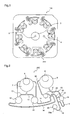
- Figure 1 is a diagram illustrating a pattern formation surface of a biological sample analysis plate according to a first embodiment of the present invention.
- Figure 2 is a diagram illustrating a pattern that is formed on the biological sample analysis plate according to the first embodiment of the present invention.
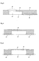
- Figure 3 is a cross-sectional view of a sample injection part or a buffer agent injection part in the biological sample analysis plate according to the first embodiment of the present invention.
- Figure 4 is a cross-sectional view illustrating a chamber part, or a sample holding part, or a buffer part in the biological sample analysis plate according to the first embodiment of the present invention.
- Figure 5 is a cross-sectional view illustrating a positive electrode part or a negative electrode part in the biological sample analysis plate according to the first embodiment of the present invention.
- Figure 6(a) is a diagram illustrating the state of a DNA conjugate when the biological sample analysis plate pattern according to the first embodiment is filled with a sample.
- Figure 6(b) is an enlarged view of a sample quantity determination part, illustrating the state of the DNA conjugate when the biological sample analysis plate pattern according to the first embodiment is filled with the sample.
- Figure 7 is a diagram illustrating the states of the respective samples when the biological sample analysis plate according to the first embodiment which is filled with the DNA conjugate and the DNA sample is rotated at 4000rpm.
- Figure 8 is a diagram illustrating the states of the respective samples when the biological sample analysis plate according to the first embodiment which is filled with the DNA conjugate and the DNA sample is rotated at 4000rpm and then suddenly stopped.
- Figure 9 is a diagram illustrating the states of the respective samples when the biological sample analysis plate according to the first embodiment which is filled with the DNA conjugate and the DNA sample is rotated at 4000rpm, suddenly stopped, and again rotated.
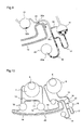
- Figure 10 is a diagram illustrating a part for performing DNA scanning, of the biological sample analysis plate pattern according to the first embodiment of the present invention.
- Figure 11 is a diagram illustrating the state where the sample quantity determination part formed in the biological sample analysis plate according to the first embodiment is filled with the DNA sample, and the DNA sample migrates in the DNA conjugate for separation that is filled in the first channel.
-
- 100
- biological sample analysis plate
- 200
- pattern
- 3
- hole for fixing a rotation part
- 4
- positioning hole
- 5
- plate gravity
- 6
- buffer agent inlet
- 7
- buffer agent injection part
- 8
- sample inlet
- 9
- sample injection part
- 10
- first channel
- 11
- second channel
- 12
- positive electrode part
- 13
- negative electrode part
- 14
- third channel
- 15
- channel
- 16
- chamber part (first chamber)
- 17
- channel
- 18
- channel (first microchannel)
- 19
- channel (second microchannel)
- 20
- sample holding part (second chamber)
- 20a
- opening
- 21
- buffer part (third chamber)
- 22, 50
- channel
- 23
- sample quantity determination part
- 24
- groove
- 25
- channel
- 26
- channel
- 27
- film
- 28
- channel
- 29
- channel
- 30
- electrode part
- 31
- DNA conjugate
- 32
- DNA sample
- 34
- air
- 35
- portion
- 36
- portion
- 37
- film
- 40
- arc portion
- 80
- sample supply channel
- 90
- buffer agent supply channel
- A
- electrophoresis direction
- Hereinafter, a biological sample analysis plate according to a first embodiment of the present invention will be described with reference to figures 1~14.
- In the present invention, a biological sample is migrated in a buffer agent to promote biological, enzymatical, immunological, and chemical reactions, thereby to discriminate the biological sample easily, inexpensively, and accurately in a short time.
- In this first embodiment, in order to specify the description, it is assumed that the biological sample is a DNA sample, and the buffer agent includes a DNA conjugate for separation and a DNA bonding control agent. The biological sample analysis plate adds a predetermined quantity of the DNA sample into the DNA conjugate for separation which is filled in a channel to make the sample perform electrophoresis in the conjugate, and detects fluorescence or absorbance in the channel to determine presence/absence of SNPs (Single Nucleotide Polymorphisms) in the DNA sample.
- Initially, the construction of the biological
sample analysis plate 100 according to the first embodiment will be described with reference to figures 1~5. Figure 1 is a diagram illustrating the biologicalsample analysis plate 100 viewed from a channel formation surface, according to the first embodiment. - Figure 2 is a diagram illustrating a specific shape of a
channel pattern 200 formed on the biologicalsample analysis plate 100 of the first embodiment shown in figure 1. The channel pattern comprises fine channels that are formed by grooves having minute width and depth, which channels are to be used for discrimination of a biological sample. In this first embodiment, the depth of the channels of thechannel pattern 200 is 50 microns. - On the biological
sample analysis plate 100 according to the first embodiment, eight channel patterns identical to thepattern 200 shown in figure 2 are radially formed, whereby DNA discriminations for eight analytes can be performed simultaneously. - As shown in figure 1, the outer shape of the biological
sample analysis plate 100 according to the first embodiment is an 8cm square, three corners out of four corners thereof are rounded, and remaining one corner is chamfered. - Further, a
hole 4 is formed to make the outer shape of theplate 100 asymmetrical so that the positions of the patterns can be specified. As a material of theplate 100, an acrylic plastic is adopted, and its thickness is 2mm. Further, grooves are formed on the channel formation surface, and an acrylic film having a thickness of 50 µm is adhered onto the surface, thereby producing hermetically closed channels. Furthermore, ahole 3 for fixing the biologicalsample analysis plate 100 onto a rotation unit is produced around agravity center 5 of theplate 100. - As shown in figure 2, a DNA conjugate as a buffer agent is injected from a
buffer agent inlet 6, and the injected buffer agent is temporarily stored in a bufferagent injection part 7. A DNA sample injected from asample inlet 8 is temporarily stored in asample injection part 9. The bufferagent injection part 7 and thesample injection part 9 are similar in shape, and a peripheral cross section thereof is shown in figure 3. - Figure 3 is a diagram illustrating a cross section of the buffer
agent injection part 7 or thesample injection part 9 and its vicinity, wherein diagonally hatched portions correspond to the biologicalsample analysis plate 100. In figure 3, aportion 35 corresponds to thebuffer agent inlet 6 and thesample inlet 8, and aportion 36 corresponds to the bufferagent injection part 7 and thesample injection part 9. Afilm 37 is the above-mentioned acrylic film, and a closed channel is formed by adhering thefilm 37 so as to cover thegroove 24. The channel formation surface is on the lower side. - A
positive electrode part 12 is an insertion part for a positive electrode, and anegative electrode part 13 is an insertion part of a negative electrode. Theseelectrode parts channel 14, and further connected to the bufferagent insertion part 7 through achannel 10 and achannel 11. Achamber part 16 is connected to thesample injection part 9 through achannel 15. - Further, a
sample holding part 20 is connected to thechamber part 16 through achannel 17 and achannel 18, and thechannel 17 is narrow while thechannel 18 is wider than thechannel 17. In this first embodiment, the width of thechannel 17 is 100µm while the width of thechannel 18 is 200µm. - A
buffer part 21 is connected to thechamber part 16 and to thesample holding part 20 through thechannels chamber part 16 is realized by achannel 50 while air releasing from thebuffer part 21 is realized by achannel 22. - A sample
quantity determination part 23 is provided at a junction between thechannel 14 and thechannel 19, and determines a quantity of the DNA sample. - The
chamber part 16, thesample holding part 20, and thebuffer part 21 are identical in shape, and a cross-sectional view of each part and its vicinity is shown in figure 4. In figure 4, the channel formation surface is on the lower side. - A
groove 24 corresponds to thechamber part 16, thesample holding part 20, or thebuffer part 21, and it has a vassal shape having a depth of 1.5mm. Achannel 25 and achannel 26 extend from each part. - Next, the
positive electrode part 12 and thenegative electrode part 13 will be described with reference to figure 5. - Figure 5 is a cross-sectional view illustrating the
positive electrode part 12 or thenegative electrode part 13 and its vicinity. The channel formation surface is on the lower side. - An
electrode part 30 corresponds to thepositive electrode part 12 or thenegative electrode part 13, and it is a hole penetrating through the biologicalsample analysis plate 100. Afilm 37 and afilm 27 are attached to the both surfaces, and thefilm 37 is required to be made of a non-conductive material while thefilm 27 may be made of a conductive material. When thefilm 27 is conductive, voltage can be applied to the sample inside theelectrode part 30 by applying voltage to thefilm 27 from the outside. When thefilm 27 is non-conductive, a needle-shaped electrode is inserted through thefilm 27 into theelectrode part 30, whereby voltage application is realized. - Further, the
film 37 is attached to the entire surface of the biologicalsample analysis plate 100 while thefilm 27 is attached to only a portion in the vicinity of theelectrode part 30. - Hereinafter, a description will be given of examples of specific control and operation to be performed until presence/absence of SNPs (Single Nucleotide Polymorphisms) in the DNA sample is determined, with reference to figure 2.
- Initially, a DNA sample as an analyte is prepared.
- Essentially, DNA has a duplex-strand helical structure. In this first embodiment, however, single-strand DNA having a base length of about 60 bases including SNP sites to be discriminated is prepared.
- Since extraction and denaturation for the single-strand DND are not directly related to the present invention, specific description thereof will be omitted.
- Next, a DNA conjugate is prepared as a buffer agent.
- A DNA conjugate is obtained by covalently bonding a high-molecular linear polymer to a 5' end of single-strand DNA having a base length of 6~12 bases. Further, the DNA conjugate has a sequence that is complemental to normal DNA but non-complemental to mutant DNA, and the bonding force to the normal DNA is strong while the bonding force to the mutant DNA is weak. Further, when performing electrophoresis, the electrophoresis speed is considerably reduced because the linear polymer bonded to the 5' end acts as a weight. It is assumed that the "DNA conjugate" described hereinafter is a material containing a pH buffer agent that also serves as an electrolyte, and a DNA bonding force control agent such as MgCl2.
- When preparation of the samples is completed, the DNA conjugate and the DNA sample are injected into the
plate 100. A predetermined amount of the DNA conjugate is dispensed from thebuffer agent inlet 6 into the bufferagent injection part 7 using a pipeter or the like. Likewise, a predetermined amount of the DNA sample is dispensed from thesample inlet 8 into thesample injection part 9. - Although the dispensing amount depends on the scale of the pattern, it is assumed that, in this first embodiment, the amount of the DNA conjugate is 18 microliters and the amount of the DNA sample is 2 microliters.
- Next, the biological
sample analysis plate 100 is fixed to a motor or the like, and rotated around thegravity center 5. At this time, the dispensed DNA conjugate and DNA sample migrate toward the outer circumference due to a centrifugal force. - The DNA conjugate in the buffer
agent injection part 7 passes through thechannel 10 and thechannel 11, and is equally separated to thepositive electrode part 12 and thenegative electrode part 13. The DNA conjugate that migrates into thepositive electrode part 12 further passes through thechannel 14 to reach the samplequantity determination part 23. Likewise, the DNA conjugate that migrates into thenegative electrode part 13 also passes through thechannel 14 to reach the samplequantity determination part 23. - Figure 6(a) shows the state where the migration of the DNA conjugate is stopped two minutes after the start of rotation. Further, figure 6(b) is an enlarged value of the sample
quantity determination part 23 and its vicinity. - The
DNA conjugate 31 is filled up to about 70% of thepositive electrode part 12 and thenegative electrode part 13, and further, it is filled in thechannel 14 to reach the samplequantity determination part 23 as shown in figure 6(b). - The fluid surface level of the DNA conjugate existing in the
positive electrode part 12 and thenegative electrode part 13 and the fluid surface level of the DNA conjugate existing in the samplequantity determination part 23 are on the same circumference with thegravity center 5 as its center. - Next, migration of the injected DNA sample will be described with reference to figures 2 and 7.
- The DNA sample in the
sample injection part 9 passes through thechannel 15 to reach thechamber part 16, and further, it passes through thechannels sample holding part 20 that is positioned on the outer circumference side. At this time, the air in thechamber part 16 is released through thechannels channel 18 is connected to the outer circumference side of thesample holding part 20, and thesample holding part 20 has no hole for air releasing. Therefore, the air remaining in thesample holding part 20 is not released but compressed. - Figure 7 shows the states of the
DNA sample 32 and theDNA sample 33 two minutes after the start of rotation.Air 34 is compressed, and the state where the centrifugal force and the pressurization force are balanced is maintained only during rotation. In this first embodiment, the rotation speed is 4000rpm. - Next, the subsequent operation will be described.
- The biological
sample analysis plate 100 is rotated for a predetermined period of time, and the rotation is suddenly stopped under the state where the migrations of the DNA conjugate and the DNA sample are stopped. For example, the rotation at 4000rpm is stopped within two seconds. - The
DNA sample 32 existing in thesample holding part 20 loses the centrifugal force, and starts to flow back into thechannel 18 from thesample holding part 20 due to the pressure of theair 34. - Further, the
DNA sample 32 migrates to thechannel 17 and thechannel 19 until theair 34 in thesample holding part 20 becomes equal to the atmosphere pressure. At this time, since thechannel 17 is narrower than thechannel 19,more DNA sample 32 is apt to flow into thechannel 19 than into thechannel 17. - Figure 8 shows the state immediately after the sudden stop.
- The
DNA sample 32 in thesample holding part 20 passes through thechannels quantity determination part 23 and thebuffer part 21 due to expansion of theair 34. - Especially in the sample
quantity determination part 23, theDNA sample 32 contacts the filledDNA conjugate 31. At this time, there exists a certain quantity of theDNA sample 32 which passes through thechannel 17 to reach thechamber part 16. - Next, the biological
sample analysis plate 100 is again rotated at a medium speed for a few seconds. At this time, it is important to perform deceleration smoothly. Figure 9 shows the state after the rotation is stopped. - While the
DNA sample 32 filled in thechannel 19 flows to thechamber part 16, a slight quantity of theDNA sample 32 remains in the samplequantity determination part 23. The remainingDNA sample 32a is electrically isolated from theother DNA samples - The reason why the second rotation is performed at a speed different from that of the first rotation is as follows. That is, when the rotation speed of the second rotation is reduced and the deceleration speed thereof is smoothed, the air 74 in the sample holding part 60 is prevented from being strongly compressed. Accordingly, the
channel 19 is prevented from being filled again with the DNA sample in thesample holding part 20 which flows back to thechannel 19. - The
sample DNA 32 that remains in the samplequantity determination part 23 after the above-mentioned operation is used as a final sample to be subjected to discrimination of SNPs. - Next, electrophoresis is carried out as follows. A positive electrode and a negative electrode are inserted in the
positive electrode part 12 and thenegative electrode part 13, respectively, and a voltage of several hundreds volts is applied. Then, electrical fields occur in thechannel 14 and in the samplequantity determination part 23, whereby a predetermined amount of theDNA sample 32 that remains in the samplequantity determination part 23 migrates in thechannel 14 toward the positive electrode side (direction A in figure 9). - The
channel 14 is filled with the DNA conjugate, and theDNA sample 32 performs electrophoresis while repeating bonding with the DNA conjugate. At this time, as described above, the electrophoresis speed of the normal DNA in theDNA sample 32 is reduced because the bonding force of the normal DNA with the DNA conjugate is strong, while the electrophoresis speed of the mutant DNA is increased relative to the normal DNA because the bonding force of the mutant DNA with the DNA conjugate is weak. That is, when both the normal DNA and the mutant DNA exist in the DNA sample, the normal DNA and the mutant DNA are separated from each other, thereby performing discrimination of SNPs. - Figure 11 is a graph obtained by scanning the
DNA 32 while the DNA sample performs electrophoresis in anarc portion 40 of thechannel 14 shown in figure 10. - Detection of DNA is carried out by exciting the fluorescent-label (FITC) modified DNA with light of 470nm, and performing detection of light in the vicinity of 520nm. This DNA detection may be carried out by detecting absorption of light at 260nm.
- In figure 11, the abscissa indicates the position of the
arc portion 40, and the DNA migrates from left to right. That is, the samplequantity determination part 23 is on the left side, and thepositive electrode part 12 is on the right side. The ordinate indicates the fluorescence intensity, showing the waveform that varies with time for every one minute. It is found that two peaks are gradually separated from each other. In this case, it is determined that the same quantities of the normal DNA and the mutant DNA exist in theDNA sample 32. - In the graph, the right-side peak shows the mutant DNA because the electrophoresis speed thereof is high, while the left-side peak shows the normal DNA because the electrophoresis speed thereof is low.
- As described above, according to the biological
sample analysis plate 100 of the first embodiment, in the biologicalsample analysis plate 100 for discriminating a biological sample by detecting a transport reaction that is obtained when the biological sample is migrated in a buffer agent, the samplequantity determination part 23 for holding a predetermined volume of the biological sample is provided at the junction between the second channel 90 in which the buffer agent flows and the first channel 80 in which the biological sample flows, and the biological sample is supplied to the samplequantity determination part 23, and further, thesample holding part 20 having theopening 20a on the outer circumference side of the biologicalsample analysis plate 100 is provided contacting thechannel 18 for supplying the biological sample to the samplequantity determination part 23. Thereby, a predetermined amount of theDNA sample 32 can be held in the samplequantity determination part 23 on the biologicalsample analysis plate 100 by only the rotating operation of theplate 100, and theDNA sample 32 can be made to perform electrophoresis by thepositive electrode part 12, thenegative electrode part 13, and thechannel 14. Furthermore, since a portion of thechannel 14 for electrophoresis which is the second channel 90 where the buffer agent flows is shaped in an arc, an extremely accurate detection result can be obtained when the DNA sample which is a specific DNA taken out of cells or blood is measured on the biological sample analysis plate. - A biological sample analysis plate according to the present invention is very useful for performing discrimination of a biological sample such as a DNA sample inexpensively and easily.
Claims (9)
- A biological sample analysis plate in which microchannels are formed, having a construction for optically or electrochemically analyzing a biological sample that flows in the microchannels, wherein
a first chamber that is provided on an inner circumference side with respect to a rotation center of the biological sample analysis plate and a second chamber that is provided on an outer circumference side thereof are connected by a first microchannel so as to permit the biological sample to move between the first chamber and the second chamber through the first microchannel, and
the second chamber previously contains air inside, and when the biological sample moves from the first chamber toward the second chamber due to a centrifugal force that is caused by rotation of the biological sample analysis plate, the air in the second chamber is compressed and held in the second chamber. - A biological sample analysis plate as defined in Claim 1 wherein an opening of the second chamber communicating to the first chamber is formed on a portion of an outer wall of the second chamber, which portion is on the outer circumference side of the analysis plate.
- A biological sample analysis plate as defined in Claim 1 wherein
a second microchannel is further connected to the first microchannel that is connected to the second chamber, and
the biological sample held in the second chamber is movable through the first microchannel and the second microchannel. - A biological sample analysis plate as defined in Claim 2 wherein
a second microchannel is further connected to the first microchannel that is connected to the second chamber, and
the biological sample held in the second chamber is movable through the first microchannel and the second microchannel. - A biological sample analysis plate as defined in Claim 4 wherein
a third chamber is connected to the second microchannel,
said third chamber is disposed in a position closer to the rotation center of the biological sample analysis plate than the first chamber, and
the biological sample is movable from the second chamber to the third chamber through the second microchannel. - A biological sample analysis plate as defined in any of Claims 3 to 5 wherein a buffer agent supply channel which has a portion connected to a sample supply channel that comprises the first microchannel and the second microchannel, and forms a sample quantity determination and holding part at the connected portion, has an arc portion with the gravity of the biological sample analysis plate being a center of the arc.
- A biological sample analysis plate as defined in any of Claims 1 to 6, said biological sample analysis plate being for antigen-antibody reaction analysis.
- A biological sample analysis plate as defined in any of Claims 1 to 6, said biological sample analysis plate being for blood component analysis.
- A biological sample analysis plate as defined in any of Claims 1 to 6, said biological sample analysis plate being for gene analysis.
Applications Claiming Priority (2)
| Application Number | Priority Date | Filing Date | Title |
|---|---|---|---|
| JP2004355142 | 2004-12-08 | ||
| PCT/JP2005/022525 WO2006062149A1 (en) | 2004-12-08 | 2005-12-08 | Plate for biological sample analysis |
Publications (2)
| Publication Number | Publication Date |
|---|---|
| EP1832872A1 true EP1832872A1 (en) | 2007-09-12 |
| EP1832872A4 EP1832872A4 (en) | 2009-07-29 |
Family
ID=36577972
Family Applications (1)
| Application Number | Title | Priority Date | Filing Date |
|---|---|---|---|
| EP05814150A Withdrawn EP1832872A4 (en) | 2004-12-08 | 2005-12-08 | PLATE OF ANALYSIS OF BIOLOGICAL SAMPLES |
Country Status (5)
| Country | Link |
|---|---|
| US (1) | US20080075632A1 (en) |
| EP (1) | EP1832872A4 (en) |
| JP (1) | JPWO2006062149A1 (en) |
| CN (1) | CN101073003B (en) |
| WO (1) | WO2006062149A1 (en) |
Cited By (3)
| Publication number | Priority date | Publication date | Assignee | Title |
|---|---|---|---|---|
| DE102008010436A1 (en) * | 2008-02-21 | 2009-09-03 | Berthold Technologies Gmbh & Co. Kg | Apparatus and method for measuring luminescence and fluorescence of transfected cells or organ parts |
| WO2013149762A1 (en) * | 2012-04-04 | 2013-10-10 | Robert Bosch Gmbh | Chamber component for a reagent vessel, and use thereof |
| WO2015049112A1 (en) * | 2013-10-01 | 2015-04-09 | Hahn-Schickard-Gesellschaft für angewandte Forschung e.V. | Fluidic module, device and method for aliquoting a liquid |
Families Citing this family (5)
| Publication number | Priority date | Publication date | Assignee | Title |
|---|---|---|---|---|
| JP4597091B2 (en) * | 2006-05-24 | 2010-12-15 | 株式会社日立ハイテクノロジーズ | Biochemical analyzer and inspection cartridge used therefor |
| JP2007330201A (en) * | 2006-06-16 | 2007-12-27 | Ab Size:Kk | Microchip for collecting cell and method for collecting cell |
| DE102012202775B4 (en) * | 2012-02-23 | 2016-08-25 | Hahn-Schickard-Gesellschaft für angewandte Forschung e.V. | FLUIDIKMODUL, DEVICE AND METHOD FOR PUMPING A LIQUID |
| GB2516675A (en) | 2013-07-29 | 2015-02-04 | Atlas Genetics Ltd | A valve which depressurises, and a valve system |
| GB2516672B (en) * | 2013-07-29 | 2015-05-20 | Atlas Genetics Ltd | A system and method for expelling liquid from a fluidic cartridge |
Family Cites Families (13)
| Publication number | Priority date | Publication date | Assignee | Title |
|---|---|---|---|---|
| DE69422604T2 (en) * | 1994-03-08 | 2000-06-08 | Zeptosens Ag, Witterwil | Apparatus and method that combine bioaffinity assay and electrophoretic separation |
| US20010055812A1 (en) * | 1995-12-05 | 2001-12-27 | Alec Mian | Devices and method for using centripetal acceleration to drive fluid movement in a microfluidics system with on-board informatics |
| JP3623479B2 (en) * | 1999-06-22 | 2005-02-23 | テカン トレーディング アーゲー | Apparatus and method for performing miniaturized in vitro amplification assays |
| JP2003533681A (en) * | 2000-05-15 | 2003-11-11 | テカン・トレーディング・アクチェンゲゼルシャフト | Microfluidic device and method for performing cell-based analysis |
| WO2002075776A1 (en) * | 2001-03-19 | 2002-09-26 | Gyros Ab | A microfluidic system (ms) |
| JP3749991B2 (en) * | 2001-10-18 | 2006-03-01 | アイダエンジニアリング株式会社 | Micro liquid weighing structure and microchip having the structure |
| DE60200822T2 (en) * | 2001-10-18 | 2005-09-15 | Aida Engineering, Ltd., Sagamihara | Microdosing and sampling device and microchip with this device |
| JP4095886B2 (en) * | 2002-05-08 | 2008-06-04 | 株式会社日立ハイテクノロジーズ | Chemical analysis device and genetic diagnosis device |
| CN1477400A (en) * | 2002-08-23 | 2004-02-25 | 汶 连 | Microfluid system and method for controlling movement of microfluid in microfluid system |
| CN1482465A (en) * | 2002-09-13 | 2004-03-17 | 上海博N微晶科技有限公司 | Axial center variable micro-fluid system and method for controlling movement of micro-fluid in the same system |
| WO2004113871A2 (en) * | 2003-06-19 | 2004-12-29 | Nagaoka & Co., Ltd. | Fluidic circuits for sample preparation including bio-discs and methods relating thereto |
| US20040265172A1 (en) * | 2003-06-27 | 2004-12-30 | Pugia Michael J. | Method and apparatus for entry and storage of specimens into a microfluidic device |
| JP4336834B2 (en) * | 2003-10-03 | 2009-09-30 | 独立行政法人物質・材料研究機構 | Chip usage and inspection chip |
-
2005
- 2005-12-08 EP EP05814150A patent/EP1832872A4/en not_active Withdrawn
- 2005-12-08 WO PCT/JP2005/022525 patent/WO2006062149A1/en not_active Ceased
- 2005-12-08 US US11/792,521 patent/US20080075632A1/en not_active Abandoned
- 2005-12-08 JP JP2006546748A patent/JPWO2006062149A1/en active Pending
- 2005-12-08 CN CN2005800421851A patent/CN101073003B/en not_active Expired - Fee Related
Cited By (4)
| Publication number | Priority date | Publication date | Assignee | Title |
|---|---|---|---|---|
| DE102008010436A1 (en) * | 2008-02-21 | 2009-09-03 | Berthold Technologies Gmbh & Co. Kg | Apparatus and method for measuring luminescence and fluorescence of transfected cells or organ parts |
| WO2013149762A1 (en) * | 2012-04-04 | 2013-10-10 | Robert Bosch Gmbh | Chamber component for a reagent vessel, and use thereof |
| WO2015049112A1 (en) * | 2013-10-01 | 2015-04-09 | Hahn-Schickard-Gesellschaft für angewandte Forschung e.V. | Fluidic module, device and method for aliquoting a liquid |
| US10882039B2 (en) | 2013-10-01 | 2021-01-05 | Hahn-Schickard-Gesellschaft Fuer Angewandte Forschung E.V. | Fluidic module, device and method for aliquoting a liquid |
Also Published As
| Publication number | Publication date |
|---|---|
| JPWO2006062149A1 (en) | 2008-06-12 |
| CN101073003B (en) | 2011-07-06 |
| EP1832872A4 (en) | 2009-07-29 |
| WO2006062149A1 (en) | 2006-06-15 |
| CN101073003A (en) | 2007-11-14 |
| US20080075632A1 (en) | 2008-03-27 |
Similar Documents
| Publication | Publication Date | Title |
|---|---|---|
| EP1181541B1 (en) | Apparatus and method for sample analysis | |
| US6207031B1 (en) | Methods and apparatus for processing a sample of biomolecular analyte using a microfabricated device | |
| US6150180A (en) | High throughput screening assay systems in microscale fluidic devices | |
| EP1313552B1 (en) | Capillary array and related methods | |
| AU2003228395B2 (en) | Methods and apparatus for separation and isolation of components from a biological sample | |
| EP1404448B1 (en) | Microfluidic chemical assay apparatus and method | |
| EP2008090B1 (en) | Method for introducing a plurality of solutions into a microfluidic channel | |
| Jayamohan et al. | Advances in microfluidics and lab-on-a-chip technologies | |
| KR19990072013A (en) | Apparatus and method using centripetal acceleration to drive fluid flow in microfluidic systems by informatics | |
| EP1712916A1 (en) | Biological sample discriminating device, biological sample discriminating method, and biological sample discriminating plate | |
| AU2002329526A1 (en) | Microfluidic chemical assay apparatus and method | |
| US20020076806A1 (en) | Sample injector system and method | |
| US20080075632A1 (en) | Biological Sample Analysis Plate | |
| KR101718951B1 (en) | Biomolecular preconcentration device and fabrication method thereof | |
| CA2362412C (en) | Test card for analysis of chemical, biochemical or biological analytes | |
| Ricco et al. | Application of disposable plastic microfluidic device arrays with customized chemistries to multiplexed biochemical assays | |
| US20060160210A1 (en) | Biological sample analysis plate | |
| US20070163885A1 (en) | Electrophoresis apparatus | |
| EP4327090B1 (en) | Device for volume coupling in epitachophoresis | |
| JP2006242612A (en) | Biological sample discrimination plate | |
| EP1902784B1 (en) | Method of removing air bubbles from hybridization solution of microarray-coverslip assembly | |
| JP2006308447A (en) | Biological sample analysis plate and biological sample analysis method | |
| JP2007075051A (en) | Biological sample discrimination plate | |
| JP2006220531A (en) | Biological sample discrimination plate | |
| EP1419821A1 (en) | Method, system and reaction vessel for processing a biological sample contained in a liquid |
Legal Events
| Date | Code | Title | Description |
|---|---|---|---|
| PUAI | Public reference made under article 153(3) epc to a published international application that has entered the european phase |
Free format text: ORIGINAL CODE: 0009012 |
|
| 17P | Request for examination filed |
Effective date: 20070625 |
|
| AK | Designated contracting states |
Kind code of ref document: A1 Designated state(s): DE FR GB |
|
| RIN1 | Information on inventor provided before grant (corrected) |
Inventor name: MORI, KAZUYOSHIC/O MATSUSHITA ELECTRIC INDUST. CO. Inventor name: NANJO, TOSHIFUMIC/O MATSUSHITA ELECT. IND. CO., LT Inventor name: SHIMIZU, RYUJIC/O MATSUSHITA ELECT. IND. CO., LTD. Inventor name: YAMASHITA, MOTOHIROC/O MATSUSHITA ELECT. IND. CO., |
|
| RBV | Designated contracting states (corrected) |
Designated state(s): DE FR GB |
|
| DAX | Request for extension of the european patent (deleted) | ||
| RAP1 | Party data changed (applicant data changed or rights of an application transferred) |
Owner name: PANASONIC CORPORATION |
|
| A4 | Supplementary search report drawn up and despatched |
Effective date: 20090629 |
|
| 17Q | First examination report despatched |
Effective date: 20091007 |
|
| RAP1 | Party data changed (applicant data changed or rights of an application transferred) |
Owner name: PANASONIC HEALTHCARE CO., LTD. |
|
| STAA | Information on the status of an ep patent application or granted ep patent |
Free format text: STATUS: THE APPLICATION IS DEEMED TO BE WITHDRAWN |
|
| 18D | Application deemed to be withdrawn |
Effective date: 20141015 |