EP1832864B1 - Accelerated weathering test apparatus and method with power level control based on full spectrum calibration - Google Patents
Accelerated weathering test apparatus and method with power level control based on full spectrum calibration Download PDFInfo
- Publication number
- EP1832864B1 EP1832864B1 EP07109363A EP07109363A EP1832864B1 EP 1832864 B1 EP1832864 B1 EP 1832864B1 EP 07109363 A EP07109363 A EP 07109363A EP 07109363 A EP07109363 A EP 07109363A EP 1832864 B1 EP1832864 B1 EP 1832864B1
- Authority
- EP
- European Patent Office
- Prior art keywords
- light source
- level
- irradiance
- data set
- group
- Prior art date
- Legal status (The legal status is an assumption and is not a legal conclusion. Google has not performed a legal analysis and makes no representation as to the accuracy of the status listed.)
- Expired - Lifetime
Links
- 238000012360 testing method Methods 0.000 title claims abstract description 98
- 238000000034 method Methods 0.000 title claims abstract description 18
- 238000001228 spectrum Methods 0.000 title claims abstract description 7
- 230000004044 response Effects 0.000 claims abstract description 13
- 238000005259 measurement Methods 0.000 claims description 21
- 229910052724 xenon Inorganic materials 0.000 claims description 7
- FHNFHKCVQCLJFQ-UHFFFAOYSA-N xenon atom Chemical compound [Xe] FHNFHKCVQCLJFQ-UHFFFAOYSA-N 0.000 claims description 7
- QSHDDOUJBYECFT-UHFFFAOYSA-N mercury Chemical compound [Hg] QSHDDOUJBYECFT-UHFFFAOYSA-N 0.000 claims description 5
- 229910052753 mercury Inorganic materials 0.000 claims description 5
- 229910001507 metal halide Inorganic materials 0.000 claims description 5
- 150000005309 metal halides Chemical class 0.000 claims description 5
- 238000012545 processing Methods 0.000 claims description 5
- 230000005465 channeling Effects 0.000 claims description 2
- 230000006870 function Effects 0.000 claims description 2
- -1 fluorescent Inorganic materials 0.000 claims 3
- 238000012544 monitoring process Methods 0.000 abstract description 5
- 239000000463 material Substances 0.000 description 5
- 230000005855 radiation Effects 0.000 description 4
- XLYOFNOQVPJJNP-UHFFFAOYSA-N water Substances O XLYOFNOQVPJJNP-UHFFFAOYSA-N 0.000 description 4
- 230000003287 optical effect Effects 0.000 description 3
- 230000032683 aging Effects 0.000 description 2
- 238000001914 filtration Methods 0.000 description 2
- WFKWXMTUELFFGS-UHFFFAOYSA-N tungsten Chemical compound [W] WFKWXMTUELFFGS-UHFFFAOYSA-N 0.000 description 2
- 229910052721 tungsten Inorganic materials 0.000 description 2
- 239000010937 tungsten Substances 0.000 description 2
- 230000001143 conditioned effect Effects 0.000 description 1
- 238000001816 cooling Methods 0.000 description 1
- 238000011161 development Methods 0.000 description 1
- 230000018109 developmental process Effects 0.000 description 1
- 239000004744 fabric Substances 0.000 description 1
- 238000007620 mathematical function Methods 0.000 description 1
- 238000005192 partition Methods 0.000 description 1
- 230000035945 sensitivity Effects 0.000 description 1
- 239000007921 spray Substances 0.000 description 1
- 238000005507 spraying Methods 0.000 description 1
- 229910001220 stainless steel Inorganic materials 0.000 description 1
- 239000010935 stainless steel Substances 0.000 description 1
- 238000007655 standard test method Methods 0.000 description 1
- 230000003068 static effect Effects 0.000 description 1
- 239000000126 substance Substances 0.000 description 1
- 230000009897 systematic effect Effects 0.000 description 1
Images





Classifications
-
- G—PHYSICS
- G01—MEASURING; TESTING
- G01N—INVESTIGATING OR ANALYSING MATERIALS BY DETERMINING THEIR CHEMICAL OR PHYSICAL PROPERTIES
- G01N21/00—Investigating or analysing materials by the use of optical means, i.e. using sub-millimetre waves, infrared, visible or ultraviolet light
- G01N21/17—Systems in which incident light is modified in accordance with the properties of the material investigated
- G01N21/25—Colour; Spectral properties, i.e. comparison of effect of material on the light at two or more different wavelengths or wavelength bands
- G01N21/27—Colour; Spectral properties, i.e. comparison of effect of material on the light at two or more different wavelengths or wavelength bands using photo-electric detection ; circuits for computing concentration
- G01N21/274—Calibration, base line adjustment, drift correction
-
- G—PHYSICS
- G01—MEASURING; TESTING
- G01N—INVESTIGATING OR ANALYSING MATERIALS BY DETERMINING THEIR CHEMICAL OR PHYSICAL PROPERTIES
- G01N17/00—Investigating resistance of materials to the weather, to corrosion, or to light
- G01N17/002—Test chambers
-
- G—PHYSICS
- G01—MEASURING; TESTING
- G01N—INVESTIGATING OR ANALYSING MATERIALS BY DETERMINING THEIR CHEMICAL OR PHYSICAL PROPERTIES
- G01N17/00—Investigating resistance of materials to the weather, to corrosion, or to light
- G01N17/004—Investigating resistance of materials to the weather, to corrosion, or to light to light
Definitions
- the present invention is directed to an accelerated weathering test apparatus and, more particularly, to an indoor accelerated weathering test apparatus which uses a full spectrum power distribution ("SPD") of an artificial light source for calibration, monitoring and control of the apparatus.
- SPD full spectrum power distribution
- Indoor accelerated weathering test apparatus are known to test the accelerated aging - characteristics of painted surfaces, fabrics, plastic sheeting and other materials. Such testing is accomplished by exposing the materials to be tested to high intensity radiation from an artificial light source that approximates sunlight, under conditions of controlled and sometimes high temperature and/or humidity.
- test apparatus of the present invention can be used to obtain such weathering data on an accelerated time basis, to permit product manufacturers to gain information as to how their products will stand up to weathering conditions over the months or years.
- an accelerated weathering test apparatus may use air which circulates through the system to control the temperature of samples being tested, so that they are not underheated or overheated by heater or radiation source which may be present, typically a high-intensity plasma lamp such as a xenon lamp. It is desirable for the samples being tested to be exposed to precisely predetermined conditions, to permit more accurate comparison between various testing runs and so that the weathering conditions provided by the test apparatus can be accurately predetermined and thus recreated when desired for comparison of various samples over the years.
- a rotatable rack for carrying the samples to be .tested surrounds a light source, often a xenon lamp, which emits irradiation having a substantial ultraviolet component.
- the rack is rotated typically about one revolution per minute, to avoid any systematic differences of positioning of the samples in the system.
- the typical level of irradiation imposed on the samples is approximately one SUN, which is defined in The Society of Automotive Engineers J-1885 weathering testing method to be 0.55 watt per square meter at 340 nanometers ultraviolet radiation.
- accelerated weathering test apparatus further accelerate the aging of materials by exposing such materials to an irradiance level that is higher than one SUN, for example two SUNs (or about 1.1 watts per square meter in accordance with the previous definition). It has been noted that at such higher light intensities, the irregularity of light irradiance around the rack at the area of the samples becomes larger, contributing to sample temperature variations, As a result, the- samples may be affected in their testing program by these variables.
- test apparatus monitor and control irradiance of the light source only at three discrete points of the light source SPD.
- prior art test apparatus measure light source irradiance only at 340 nanometers ("nm"), 420 nm and 300-400 nm. Measurements are made a fixed band-pass optical filter and associated closed loop feedback electronics. Standard test methods as in ISO 9370 and ISO 4892 specify one of the three control points and are not user selectable.
- test monitoring and controlling methods are particularly disadvantageous for several reasons. For example, test specimen materià1s. currently under development are sensitive to, age or degrade as a result of exposure to irradiance from the light source at specific wavelengths other than the set standard.
- test apparatus can be used to provide accurately predetermined conditions which are substantially predictable and invariant throughout a run and from run to run.
- FIG. 1 is a perspective view of a prior art accelerated weathering test apparatus.
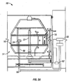
- FIG. 2A is an elevation view of an accelerated weathering test apparatus in accordance with one embodiment of the present invention.
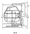
- FIG. 2B is an elevation view of an accelerated weathering test apparatus in accordance with another embodiment of the present invention.
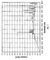
- FIG. 3 is a graphical representation of a portion of the SPD for a calibration light source monitored by a traceable spectroradiometer.
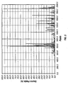
- FIG. 4 is a graphical representation of a second group of measurements from a second full SPD for the calibration light source operated in a client accelerated weathering test apparatus.
- FIG. 5 is a graphical representation of the first full SPD of the calibration light source after filtering.
- FIG. 6 is a graphical representation of the second full SPD of the calibration light source of FIG. 6 after filtering.
- FIG. 7 is a graphical representation of a system response factor of the client accelerated weathering test apparatus.
- FIG. 8 is a graphical representation of the full SPD of the client accelerated weathering test apparatus after calibration.
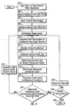
- FIG. 9 is a flow chart directed to the steps in accordance with the present invention for operating the calibrated client accelerated weathering test apparatus
- a method of exposing test specimens in a client accelerated weathering test apparatus to an accurate preselected level of irradiance includes the following steps: determining a power level for generating a preselected level of irradiance from a light source based upon a type of light source filter assembly, a first data set for a calibrated light source and a desired irradiance level set point at a control wavelength from the light source; determining a measured irradiance level from the light source based upon a second data set for the light source adjusted by a system response factor; comparing the power level against the measured irradiance level at the control wavelength; generating a light source power control signal; and repeating the above steps at preselected intervals for a desired period of time.
- an accelerated weathering test apparatus includes a test chamber.
- a test specimen mount for supporting test specimens is disposed in the test chamber.
- a light source is also disposed within the test chamber for generator irradiance.
- a controller generates a light source power control signal based upon the plurality of inputs.
- a power source is responsive to the light source power control signal for outputting power to the light source.
- a spectroradiometer collects a full SPD of the light source then generates a data set representative of the full SPD in order to output the data set to the controller as one of the plurality of inputs.
- a weathering testing device 10 which comprises a housing 12 defining an upper chamber 14 in which a rack 16 resides, comprising a roughly spherical array of stainless steel struts, to which test specimens 18 may be attached in a manner substantially equidistant from a central light source 22, which may be a xenon, fluorescent, metal halide, mercury or tungsten lamp.
- a central light source 22 which may be a xenon, fluorescent, metal halide, mercury or tungsten lamp.
- a circular arrangement of apertures 26 are provided, plus a conical baffle 24, to assist in directing air passing through apertures 26 along test samples 18 carried on the rack.
- a conventional resistance-type heater element 30 may be positioned under apertures 26 and the partition that carries them, for helping to control the temperature of the air surrounding the specimens 18.
- the fitting of the light source 22 may be in accordance with U.S. Pat. No. 5,226,318 , including both electrical and water flaw conduits for providing the same to the light source 22.
- Rack 16 is carried by a first support member or shaft 34 which extends through the top wall 36 of the upper chamber 14.
- first support member or shaft 34 which extends through the top wall 36 of the upper chamber 14.
- the connections of various electronic devices carried on rack 16 may pass with shaft 34 through top wall 36 to a microprocessor 38 that is carried in the weathering testing system above top wall 36, in a manner that is safely spaced from both the flowing water and the high electric currents and voltages used with respect to the light source 22.
- Test rack 16 may carry a black panel temperature sensor 40, which is a sensor particularly adapted to sense the temperature directly imparted by the radiation from the light source.
- a dry bulb sensor may also be provided at a position more remote from light source 22 to monitor air temperature.
- a direct percentage relative humidity sensor may be provided. Each of these can provide signal data to microprocessor 38.
- the top wall also defines wall apertures which represent the inlet of a circulatory plenum 46 that circulates air, driven by blower 28, from top to the bottom of chamber 14 and through apertures 26, as propelled by blower 28.
- plenum 46 Within plenum 46 is a variably openable cooling air supply vent 48, having a movable damper 50, and comprising air inlet 48b and air outlet 48a.
- the position of the damper 50 can be controlled by a control member 51 which is, in turn, controlled by the microprocessor 38 in a conventional manner.
- Rack water spray or atomizer unit 52 is also provided in upper chamber 14, along with a specimen water sprayer atomizer unit 53, provided for added specific spraying of the specimens when that is desired.
- weathering test machine 10 may be as disclosed in the previously cited U.S. Pat. Nos. 5,503,032 and 5,854,433 .
- FIGS. 2A and 2B an elevation view of an accelerated weathering test apparatus 10 in accordance with embodiments of the present invention are illustrated.
- the structural and functional aspects of the embodiments of the present invention are as set forth above with respect to such aspects described and explained in connection with FIG. 1 , except for the further details set forth below. Accordingly, further description of this embodiment will be directed to only those structural and functional aspects of the present embodiment and such aspects of the embodiment described in FIG. 1 necessary to support and enable the description of the embodiments in FIGS. 2A and 2B . It is within the teachings of the present invention that the structural and functional aspects of the apparatus described with respect to FIG. 1 shall apply and enable any of the embodiments of the present invention.
- the accelerated weathering test apparatus 10 of these embodiments include an upper or test chamber 14, a rack or test specimen mount 16 for supporting test specimens 18 in the test chamber 14.
- a light source 22 is disposed within the test chamber 14 for generating irradiance in the test chamber 14.
- a controller 60 generates a light source power control signal based upon a plurality of inputs, as will be discussed below.
- a power source 62 responsive to the light source power control signal for outputting power to the light source 22.
- An input device 64 is disposed within the test chamber 14 for direct interface with irradiance from the light source 22 in order to facilitate and enable monitoring of the full SPD of the light source 22.
- a data set representative of the full SPD is generated and outputted to the controller 60 as one of the plurality of inputs.
- the controller 60 determines a power level for generating a preselected level of irradiance from the light source 22 based upon a plurality of inputs.
- the plurality of inputs include at least the following: a type of light source filter assembly; a calibrated light source data set (as described below); and a desired irradiance level set point for a control wavelength from the light source 22. It is within the teachings of the present invention that additional inputs to the controller 60 may be desired and used to facilitate and enable more precise control over the power level.
- the controller further determines a measured irradiance level from the light source 22 based upon the data set for the light source 22 adjusted by a system response factor, each described in more detail below. It will be recognized by those of skill in the art that the term "data set” as used in connection with the embodiment described with respect to FIGS. 2A and 2B is equivalent to the term “second data set” as used hereafter and may be used interchangeably therewith.
- the controller 60 compares the power level and the measured irradiance level, generates a light source power control signal which is outputted to the power source 62 and repeats the above steps at preselected intervals for a desired period of time.
- the controller 60 includes a processing unit and memory that stores programming instructions that, when used by the processing unit, causes the controller to function to: determine a power level for generating a preselected level of irradiance from a light source based upon a type of light source filter assembly, a calibrated light source data set and a desired irradiance level set point at a control wavelength from the light source; determine a measured irradiance level from the light source based upon the data set for the light source adjusted by a system response factor; compare the power level and the measured irradiance level; generate a light source power control signal; and repeat the above steps at preselected intervals for a desired period of time.
- the processor in this invention may be, but not limited to, a single processor, plurality of processors, a DSP, a microprocessor, ASIC, state machine, or any other implementation capable of processing and executing software.
- the term processor should not be construed to refer exclusively to hardware capable of executing software, and may implicitly include DSP hardware, ROM for storing software, RAM, and any other volatile or non-volatile storage medium.
- the memory in this invention may be, but not limited to, a single memory, a plurality of memory locations, shared memory, CD, DVD, ROM, RAM, EEPROM, optical storage, microcode or any other non-volatile storage capable of storing digital data for use by the processor.
- the power source 62 is the same as used in connection with the prior art described in FIG. 1 . However, operation in connection with the controller 60 now enables the power source 62 to be adjusted such that a reliably consistent irradiance level is provided during any test.
- the input device may be a spectroradiometer, a receiving optic device or any other suitable input device that is disposed within the test chamber 14 for direct interface with irradiance from the light source 22 and operatively communicates with a spectroradiometer
- the input device 64 is disposed on a stand 66 within the circumference of the test specimen mount 16.
- the input device 64 is mounted on the test specimen mount 16 as would a test specimen in a test specimen plane defined by such test specimen supported by the test specimen mount or rack.
- a lightwave guide facilitates and is useful for channeling the light from the light source to the spectroradiometer which is disposed remote from the test chamber 14 or within and not exposed to direct irradiance.
- the spectroradiometer may be, but not limited to, any suitable device having a monochrometer and a photosensitive device or a diode array.
- the spectroradiometer is a linear charged coupled device that can be calibrated to National Institute of Standards and Testing ("N1ST") standards.
- N1ST National Institute of Standards and Testing
- one suitable spectroradiometer useful in connection with the present invention may be model number OL 754-C from Optronic Laboratories of Orlando, Florida.
- Other suitable spectroradiometers which facilitate or enable the functional aspects of the present invention may also be used.
- the light source 22 may be a lamp selected from the group consisting of xenon, fluorescent, metal halide, mercury and tungsten lamps. It will be recognized by those of skill in the art that other suitable light sources may be used to provide the desired results.
- FIG. 7 is a graphical representation of a system response factor of the client accelerated weathering test apparatus in accordance with one embodiment of the present invention.
- the system response factor is expressed as a signal output amplitude of each of a plurality of discreet wavelengths of a full SPD with respect to the client accelerated weathering test apparatus.
- the system response factor is useful to adjust the irradiance level control for a particular client accelerated weathering text apparatus to a NIST traceable level.
- FIG. 8 is a graphical representation of a full SPD generated by the client accelerated weathering test apparatus after calibration. It will be recognized by those of skill in the art that the graphical representation of the full SPD .of FIG. 8 is substantially identical to the graphical representation of the full SPD of FIG. 3 indicating that the irradiance level control in the client accelerating weathering test apparatus is now calibrated to a NIST-traceable level. As a result, accurate and predictable results may be obtained from the client accelerated weathering test apparatus.
- the step of collecting the first full SPD is facilitated by a NIST-traceable spectroradiometer used in connection with the factory accelerated weathering test apparatus.
- spectroradiometer may include a monochrometer and a photo-sensitive device and may be selected from the group consisting of a linear charged coupled device and a diode array.
- the step of collecting the second full SPD is facilitated by a spectroradiometer used in connection with the client, accelerated weathering test apparatus.
- a spectroradiometer used in connection with the client, accelerated weathering test apparatus.
- Such spectroradiometer preferably may include a monochrometer and a photo-sensitive device which may be selected from the group consisting of a linear charged coupled device and a diode array.
- FIG. 9 of the flow chart is directed to the steps in accordance with one embodiment of the present invention for operating the calibrated client accelerated weathering test apparatus to expose test specimens therein to an accurate pre-selected level of irradiance.
- a power level for generating a pre-selected level of irradiance from a light source is determined. The process of determining the power level is based on preceding steps 400-406. Namely, a type of light source filter assembly is inputted in step 400, a desired irradiance level set point for a control wavelength from the light source is inputted in steps 402 and 404, and a first data set for a calibrated light source is retrieved from memory in step 406.
- the client accelerated weathering test apparatus is activated in order to begin exposing test specimens to irradiance from the light source.
- a measured irradiance level from the light source is observed in step 418 based upon the preceding steps. Namely, the actual irradiance from the light source is collected and conditioned in step 412, a second data set is generated in step 414 and the second data set is adjusted by a system response factor in step 416.
- step 420 the power level and the measured irradiance level at the control wavelength are compared.
- an adjusted light source power control signal is generated in step 424 and the process resets back to step 410.
- the process of this embodiment of the present invention pauses for an interval in step 428 and, after the pause, resets the process to step 410.
- the desired time period for exposure is expired in step 426, the exposure of the test specimens in the client accelerated weathering test apparatus ends in step 430.
- control wavelength may be a range of wavelengths or a specified range of wavelengths and that such may be used to determine photometric output.
- a LUX value may be deremined from any full SPD derived in accordance with the present invention appliced to a mathematical function known to those of skill in the art. In one embodiment of the present invention, this may be characterized by the raw data weighted with respect to a human eye, i.e. photopic response.
- the first data set includes a first group of measurements from a first full SPD where each measurement of the first group of measurements is expressed as a first irradiance amplitude for each of a plurality of discreet wavelengths in equally spaced intervals over the first full SPD,
- the first group of measurements is enabled by a NIST-traceable spectroradiometer,
- the second data set includes a second group of measurements from a second full SPD where each measurement of the second group of measurements is expressed as a number of counts for each sensor element.
- the second group of measurements is enabled by a NIST-traceable spectroradiometer and such spectroradiometer may be a linear charged coupled device or any other suitable device.
Landscapes
- Life Sciences & Earth Sciences (AREA)
- Physics & Mathematics (AREA)
- General Health & Medical Sciences (AREA)
- General Physics & Mathematics (AREA)
- Pathology (AREA)
- Health & Medical Sciences (AREA)
- Immunology (AREA)
- Chemical & Material Sciences (AREA)
- Analytical Chemistry (AREA)
- Biochemistry (AREA)
- Biodiversity & Conservation Biology (AREA)
- Ecology (AREA)
- Environmental & Geological Engineering (AREA)
- Environmental Sciences (AREA)
- Engineering & Computer Science (AREA)
- Theoretical Computer Science (AREA)
- Mathematical Physics (AREA)
- Spectroscopy & Molecular Physics (AREA)
- Testing Resistance To Weather, Investigating Materials By Mechanical Methods (AREA)
- Investigating Or Analysing Materials By Optical Means (AREA)
- Spectrometry And Color Measurement (AREA)
Abstract
Description
- The present invention is directed to an accelerated weathering test apparatus and, more particularly, to an indoor accelerated weathering test apparatus which uses a full spectrum power distribution ("SPD") of an artificial light source for calibration, monitoring and control of the apparatus.
- Indoor accelerated weathering test apparatus are known to test the accelerated aging - characteristics of painted surfaces, fabrics, plastic sheeting and other materials. Such testing is accomplished by exposing the materials to be tested to high intensity radiation from an artificial light source that approximates sunlight, under conditions of controlled and sometimes high temperature and/or humidity.
- In a natural outdoor environment, heat, light and moisture combine to synergistically cause optical mechanical and chemical changes in products which are exposed to such outdoor weathering conditions. Generally, the test apparatus of the present invention and the prior art can be used to obtain such weathering data on an accelerated time basis, to permit product manufacturers to gain information as to how their products will stand up to weathering conditions over the months or years.
- Typically, an accelerated weathering test apparatus may use air which circulates through the system to control the temperature of samples being tested, so that they are not underheated or overheated by heater or radiation source which may be present, typically a high-intensity plasma lamp such as a xenon lamp. It is desirable for the samples being tested to be exposed to precisely predetermined conditions, to permit more accurate comparison between various testing runs and so that the weathering conditions provided by the test apparatus can be accurately predetermined and thus recreated when desired for comparison of various samples over the years.
- In known accelerated weathering test apparatus, a rotatable rack for carrying the samples to be .tested surrounds a light source, often a xenon lamp, which emits irradiation having a substantial ultraviolet component. The rack is rotated typically about one revolution per minute, to avoid any systematic differences of positioning of the samples in the system. Also, the typical level of irradiation imposed on the samples is approximately one SUN, which is defined in The Society of Automotive Engineers J-1885 weathering testing method to be 0.55 watt per square meter at 340 nanometers ultraviolet radiation.
- Other known accelerated weathering test apparatus further accelerate the aging of materials by exposing such materials to an irradiance level that is higher than one SUN, for example two SUNs (or about 1.1 watts per square meter in accordance with the previous definition). It has been noted that at such higher light intensities, the irregularity of light irradiance around the rack at the area of the samples becomes larger, contributing to sample temperature variations, As a result, the- samples may be affected in their testing program by these variables.
- Other known accelerated weathering test apparatus monitor and control irradiance of the light source only at three discrete points of the light source SPD. Namely, prior art test apparatus measure light source irradiance only at 340 nanometers ("nm"), 420 nm and 300-400 nm. Measurements are made a fixed band-pass optical filter and associated closed loop feedback electronics. Standard test methods as in ISO 9370 and ISO 4892 specify one of the three control points and are not user selectable. These known test monitoring and controlling methods are particularly disadvantageous for several reasons. For example, test specimen materià1s. currently under development are sensitive to, age or degrade as a result of exposure to irradiance from the light source at specific wavelengths other than the set standard. In current instruments it is not possible to control the wavelength of maximum or critical sensitivity for specific materials. Further, the SPD of the light source changes as the light source and inner and outer filters age over time. Again, with a static irradiance control wavelength the optimum accelerated weathering cannot be achieved. As a result, the reliability of the test specimens is affected in-their respective testing programs by these variables.
- By the present invention, improvements are provided which increase the accuracy of the monitoring and control of the test apparatus of this invention. In that the test apparatus can be used to provide accurately predetermined conditions which are substantially predictable and invariant throughout a run and from run to run.
- The invention may be best understood by reference to the following description taken in conjunction with the accompanying drawings, in the several figures of which like reference numerals identify like elements.
-
FIG. 1 is a perspective view of a prior art accelerated weathering test apparatus. -
FIG. 2A is an elevation view of an accelerated weathering test apparatus in accordance with one embodiment of the present invention. -
FIG. 2B is an elevation view of an accelerated weathering test apparatus in accordance with another embodiment of the present invention. -
FIG. 3 is a graphical representation of a portion of the SPD for a calibration light source monitored by a traceable spectroradiometer. -
FIG. 4 is a graphical representation of a second group of measurements from a second full SPD for the calibration light source operated in a client accelerated weathering test apparatus. -
FIG. 5 is a graphical representation of the first full SPD of the calibration light source after filtering. -
FIG. 6 is a graphical representation of the second full SPD of the calibration light source ofFIG. 6 after filtering. -
FIG. 7 is a graphical representation of a system response factor of the client accelerated weathering test apparatus. -
FIG. 8 is a graphical representation of the full SPD of the client accelerated weathering test apparatus after calibration. -
FIG. 9 is a flow chart directed to the steps in accordance with the present invention for operating the calibrated client accelerated weathering test apparatus, - In an embodiment of the present invention, a method of exposing test specimens in a client accelerated weathering test apparatus to an accurate preselected level of irradiance includes the following steps: determining a power level for generating a preselected level of irradiance from a light source based upon a type of light source filter assembly, a first data set for a calibrated light source and a desired irradiance level set point at a control wavelength from the light source; determining a measured irradiance level from the light source based upon a second data set for the light source adjusted by a system response factor; comparing the power level against the measured irradiance level at the control wavelength; generating a light source power control signal; and repeating the above steps at preselected intervals for a desired period of time.
- And another embodiment of the present invention is directed to an accelerated weathering test apparatus includes a test chamber. A test specimen mount for supporting test specimens is disposed in the test chamber. A light source is also disposed within the test chamber for generator irradiance. A controller generates a light source power control signal based upon the plurality of inputs. A power source is responsive to the light source power control signal for outputting power to the light source. A spectroradiometer collects a full SPD of the light source then generates a data set representative of the full SPD in order to output the data set to the controller as one of the plurality of inputs.
- Referring to
FIG. 1 , aweathering testing device 10 is shown, which comprises ahousing 12 defining anupper chamber 14 in which arack 16 resides, comprising a roughly spherical array of stainless steel struts, to whichtest specimens 18 may be attached in a manner substantially equidistant from acentral light source 22, which may be a xenon, fluorescent, metal halide, mercury or tungsten lamp. This arrangement is similar to that disclosed inU.S. Pat. Nos. 5,503,032 and5,854,433 . - At the bottom of upper chamber 14 a circular arrangement of
apertures 26 are provided, plus aconical baffle 24, to assist in directing air passing throughapertures 26 alongtest samples 18 carried on the rack. - A conventional resistance-type heater element 30 may be positioned under
apertures 26 and the partition that carries them, for helping to control the temperature of the air surrounding thespecimens 18. The fitting of thelight source 22 may be in accordance withU.S. Pat. No. 5,226,318 , including both electrical and water flaw conduits for providing the same to thelight source 22. -
Rack 16 is carried by a first support member orshaft 34 which extends through thetop wall 36 of theupper chamber 14. Thus, the connections of various electronic devices carried onrack 16 may pass withshaft 34 throughtop wall 36 to amicroprocessor 38 that is carried in the weathering testing system abovetop wall 36, in a manner that is safely spaced from both the flowing water and the high electric currents and voltages used with respect to thelight source 22. - A motor M is positioned above
top wall 36, which rotatesshaft 34 andrack 16.Test rack 16 may carry a blackpanel temperature sensor 40, which is a sensor particularly adapted to sense the temperature directly imparted by the radiation from the light source. A dry bulb sensor may also be provided at a position more remote fromlight source 22 to monitor air temperature. Also, a direct percentage relative humidity sensor may be provided. Each of these can provide signal data tomicroprocessor 38. - The top wall also defines wall apertures which represent the inlet of a
circulatory plenum 46 that circulates air, driven byblower 28, from top to the bottom ofchamber 14 and throughapertures 26, as propelled byblower 28. - Within
plenum 46 is a variably openable coolingair supply vent 48, having amovable damper 50, and comprisingair inlet 48b andair outlet 48a. The position of thedamper 50 can be controlled by acontrol member 51 which is, in turn, controlled by themicroprocessor 38 in a conventional manner. - Rack water spray or
atomizer unit 52 is also provided inupper chamber 14, along with a specimen watersprayer atomizer unit 53, provided for added specific spraying of the specimens when that is desired. - Further details with respect to weathering
test machine 10 may be as disclosed in the previously citedU.S. Pat. Nos. 5,503,032 and5,854,433 . - Referring to
FIGS. 2A and2B , an elevation view of an acceleratedweathering test apparatus 10 in accordance with embodiments of the present invention are illustrated. It will be recognized by those of skill in the art that the structural and functional aspects of the embodiments of the present invention are as set forth above with respect to such aspects described and explained in connection withFIG. 1 , except for the further details set forth below. Accordingly, further description of this embodiment will be directed to only those structural and functional aspects of the present embodiment and such aspects of the embodiment described inFIG. 1 necessary to support and enable the description of the embodiments inFIGS. 2A and2B . It is within the teachings of the present invention that the structural and functional aspects of the apparatus described with respect toFIG. 1 shall apply and enable any of the embodiments of the present invention. - The accelerated
weathering test apparatus 10 of these embodiments include an upper ortest chamber 14, a rack or test specimen mount 16 for supportingtest specimens 18 in thetest chamber 14. Alight source 22 is disposed within thetest chamber 14 for generating irradiance in thetest chamber 14. Acontroller 60 generates a light source power control signal based upon a plurality of inputs, as will be discussed below. Apower source 62 responsive to the light source power control signal for outputting power to thelight source 22. Aninput device 64 is disposed within thetest chamber 14 for direct interface with irradiance from thelight source 22 in order to facilitate and enable monitoring of the full SPD of thelight source 22. A data set representative of the full SPD is generated and outputted to thecontroller 60 as one of the plurality of inputs. - The
controller 60 determines a power level for generating a preselected level of irradiance from thelight source 22 based upon a plurality of inputs. Preferably, the plurality of inputs include at least the following: a type of light source filter assembly; a calibrated light source data set (as described below); and a desired irradiance level set point for a control wavelength from thelight source 22. It is within the teachings of the present invention that additional inputs to thecontroller 60 may be desired and used to facilitate and enable more precise control over the power level. - The controller further determines a measured irradiance level from the
light source 22 based upon the data set for thelight source 22 adjusted by a system response factor, each described in more detail below. It will be recognized by those of skill in the art that the term "data set" as used in connection with the embodiment described with respect toFIGS. 2A and2B is equivalent to the term "second data set" as used hereafter and may be used interchangeably therewith. Thecontroller 60 compares the power level and the measured irradiance level, generates a light source power control signal which is outputted to thepower source 62 and repeats the above steps at preselected intervals for a desired period of time. Thereby, precise and accurate operation of the accelerated weathering test apparatus that overcomes the disadvantages of the prior art may be accomplished: - Preferably, the
controller 60 includes a processing unit and memory that stores programming instructions that, when used by the processing unit, causes the controller to function to: determine a power level for generating a preselected level of irradiance from a light source based upon a type of light source filter assembly, a calibrated light source data set and a desired irradiance level set point at a control wavelength from the light source; determine a measured irradiance level from the light source based upon the data set for the light source adjusted by a system response factor; compare the power level and the measured irradiance level; generate a light source power control signal; and repeat the above steps at preselected intervals for a desired period of time. - The processor in this invention may be, but not limited to, a single processor, plurality of processors, a DSP, a microprocessor, ASIC, state machine, or any other implementation capable of processing and executing software. The term processor should not be construed to refer exclusively to hardware capable of executing software, and may implicitly include DSP hardware, ROM for storing software, RAM, and any other volatile or non-volatile storage medium.
- The memory in this invention may be, but not limited to, a single memory, a plurality of memory locations, shared memory, CD, DVD, ROM, RAM, EEPROM, optical storage, microcode or any other non-volatile storage capable of storing digital data for use by the processor.
- The
power source 62 is the same as used in connection with the prior art described inFIG. 1 . However, operation in connection with thecontroller 60 now enables thepower source 62 to be adjusted such that a reliably consistent irradiance level is provided during any test. - The input device may be a spectroradiometer, a receiving optic device or any other suitable input device that is disposed within the
test chamber 14 for direct interface with irradiance from thelight source 22 and operatively communicates with a spectroradiometer InFIG. 2A , theinput device 64 is disposed on astand 66 within the circumference of thetest specimen mount 16. InFIG. 2B , theinput device 64 is mounted on the test specimen mount 16 as would a test specimen in a test specimen plane defined by such test specimen supported by the test specimen mount or rack. - In the event the input device 69 is the receiving optic device or other suitable device other than a spectroradiometer disposed within the
test chamber 14 for direct interface with irradiance from thelight source 22 as shown in either ofFIGS. 2A or2B , a lightwave guide facilitates and is useful for channeling the light from the light source to the spectroradiometer which is disposed remote from thetest chamber 14 or within and not exposed to direct irradiance. - Generally the spectroradiometer may be, but not limited to, any suitable device having a monochrometer and a photosensitive device or a diode array. Preferably, the spectroradiometer is a linear charged coupled device that can be calibrated to National Institute of Standards and Testing ("N1ST") standards. For example, one suitable spectroradiometer useful in connection with the present invention may be model number OL 754-C from Optronic Laboratories of Orlando, Florida. Other suitable spectroradiometers which facilitate or enable the functional aspects of the present invention may also be used.
- As described above, the
light source 22 may be a lamp selected from the group consisting of xenon, fluorescent, metal halide, mercury and tungsten lamps. It will be recognized by those of skill in the art that other suitable light sources may be used to provide the desired results. -
FIG. 7 is a graphical representation of a system response factor of the client accelerated weathering test apparatus in accordance with one embodiment of the present invention. It will be recognized by those of skill in the art that the system response factor is expressed as a signal output amplitude of each of a plurality of discreet wavelengths of a full SPD with respect to the client accelerated weathering test apparatus. In other words, as will be discussed in more detail below, the system response factor is useful to adjust the irradiance level control for a particular client accelerated weathering text apparatus to a NIST traceable level. -
FIG. 8 is a graphical representation of a full SPD generated by the client accelerated weathering test apparatus after calibration. It will be recognized by those of skill in the art that the graphical representation of the full SPD .ofFIG. 8 is substantially identical to the graphical representation of the full SPD ofFIG. 3 indicating that the irradiance level control in the client accelerating weathering test apparatus is now calibrated to a NIST-traceable level. As a result, accurate and predictable results may be obtained from the client accelerated weathering test apparatus. - In one embodiment of the present invention, the step of collecting the first full SPD, is facilitated by a NIST-traceable spectroradiometer used in connection with the factory accelerated weathering test apparatus. Such spectroradiometer may include a monochrometer and a photo-sensitive device and may be selected from the group consisting of a linear charged coupled device and a diode array.
- It is within the teachings of the present invention that the step of collecting the second full SPD is facilitated by a spectroradiometer used in connection with the client, accelerated weathering test apparatus. Such spectroradiometer preferably may include a monochrometer and a photo-sensitive device which may be selected from the group consisting of a linear charged coupled device and a diode array.
-
FIG. 9 of the flow chart is directed to the steps in accordance with one embodiment of the present invention for operating the calibrated client accelerated weathering test apparatus to expose test specimens therein to an accurate pre-selected level of irradiance. Instep 408, a power level for generating a pre-selected level of irradiance from a light source is determined. The process of determining the power level is based on preceding steps 400-406. Namely, a type of light source filter assembly is inputted instep 400, a desired irradiance level set point for a control wavelength from the light source is inputted insteps step 406. Instep 410, the client accelerated weathering test apparatus is activated in order to begin exposing test specimens to irradiance from the light source. - A measured irradiance level from the light source is observed in
step 418 based upon the preceding steps. Namely, the actual irradiance from the light source is collected and conditioned instep 412, a second data set is generated instep 414 and the second data set is adjusted by a system response factor instep 416. - In
step 420, the power level and the measured irradiance level at the control wavelength are compared. In the event the measured irradiance level does not correspond with the irradiance level set point, an adjusted light source power control signal is generated instep 424 and the process resets back to step 410. In the event the measured irradiance level corresponds with the irradiance level set point and the desired time period for exposure is not expired instep 426, then the process of this embodiment of the present invention pauses for an interval instep 428 and, after the pause, resets the process to step 410. In the event the desired time period for exposure is expired instep 426, the exposure of the test specimens in the client accelerated weathering test apparatus ends instep 430. - It is within the teachings of the present invention that the control wavelength may be a range of wavelengths or a specified range of wavelengths and that such may be used to determine photometric output. For example, a LUX value may be deremined from any full SPD derived in accordance with the present invention appliced to a mathematical function known to those of skill in the art. In one embodiment of the present invention, this may be characterized by the raw data weighted with respect to a human eye, i.e. photopic response.
- In one embodiment of the present invention, the first data set includes a first group of measurements from a first full SPD where each measurement of the first group of measurements is expressed as a first irradiance amplitude for each of a plurality of discreet wavelengths in equally spaced intervals over the first full SPD, Preferably, the first group of measurements is enabled by a NIST-traceable spectroradiometer,
- Further in one embodiment of the present invention, the second data set includes a second group of measurements from a second full SPD where each measurement of the second group of measurements is expressed as a number of counts for each sensor element. The second group of measurements is enabled by a NIST-traceable spectroradiometer and such spectroradiometer may be a linear charged coupled device or any other suitable device.
Claims (20)
- A method of exposing test specimens (18) in a client accelerated weathering test apparatus (10) to an accurate preselected level of irradiance, comprising the steps of:determining a power level for generating a preselected level of irradiance from a light source (22) based upon a type of light source filter assembly, a first data set for a calibrated light source and a desired irradiance level set point at a control wavelength from the light source (22);determining a measured irradiance level from the light source (22) based upon a second data set for the light source adjusted by a system response factor;comparing the power level and the measured irradiance level at the control wavelength;generating a light source power control signal; andrepeating the above steps at preselected intervals for a desired period of time.
- A method as claimed in claim 1, wherein the light source (22) is a lamp selected from the group consisting of xenon, fluorescent, metal halide and mercury.
- A method as claimed in claim 1 or 2, wherein the calibrated light source is selected from the group consisting of xenon, fluorescent, metal halide and mercury.
- A method as claimed in any one of claims 1 to 3, wherein the control wavelength is a range of wavelengths.
- A method as claimed in any one of claims 1 to 4, wherein the control wavelength is a range of wavelengths that may be used to determine photometric output.
- A method as claimed in any one of claims 1 to 5, wherein the first data set includes a first group of measurements from a first full spectrum power distribution ("SPD") where each measurement of the first group of measurements is expressed as a first irradiance amplitude for each of a plurality of discrete wavelengths at equally spaced intervals over the first full SPD.
- A method as claimed in claim 6, wherein the first group of measurements is enabled by a National Institute of Standards and Testing ("NIST")-traceable spectroradiometer.
- A method as claimed in any one of claims 1 to 7, wherein the second data set includes a second group of measurements from a second full SPD where each measurement of the second group of measurements is expressed as a number of counts for each sensor element.
- A method as claimed in claim 8, wherein the second group of measurements is enabled by a NIST-traceable spectroradiometer.
- A method as claimed in claim 9, wherein the spectroradiometer is a linear charge-coupled device.
- An accelerated weathering test apparatus (10) comprising:(a) a test chamber (14);(b) a test specimen mount (16) for supporting test specimens (18) in the test chamber (14);(c) a light source (22) disposed within the test chamber (14) for generating irradiance in the test chamber (14);
characterized by(d) a controller (60) for generating a light source power control signal based upon a plurality of inputs, said controller (60) operative to determine a power level for generating a preselected level of irradiance from said light source (22) based upon a type of light source filter assembly, a calibrated light source data set and a desired irradiance level set point of a control wavelength from the light source (22);
determine a measured irradiance level from said light source (22) based upon the data set for the light source (22) adjusted by a system response factor; compare the power level and the measured irradience level; and
generate said light source power control signal; and(e) a power source (62) responsive to the light source power control signal for outputting power to the light source (22); and
a spectroradiometer for collecting a full spectrum power distribution ("SPD") of the light source, generating a data set representative of the full SPD and outputting the data set to the controller (60) as one of the plurality of inputs. - An apparatus as claimed in claim 11, wherein the spectroradiometer having a receiving optic device (69) is disposed within the test chamber (14) for direct interface with irradiance from the light source (22).
- An apparatus as claimed in claim 11, wherein a lightwave guide receiving optic device (69) is disposed within the test chamber (14) for direct interface with irradiance from the light source (22) and channeling light from the light source (22) to the spectroradiometer which is disposed remote from the test chamber (14).
- An apparatus as claimed in claim 13, wherein the receiving optic device (69) is disposed on the test specimen mount (16).
- An apparatus as claimed in claim 13, wherein the receiving optic device (69) is disposed in a test specimen plane defined by the test specimens (18) supported by the test specimen mount (16).
- An apparatus as claimed in any one of claims 11 to 15, wherein the data set includes a group of measurements from the full SPD where each measurement of the group of measurements is expressed as a number of counts for each sensor element.
- An apparatus as claimed in any one of claims 11 to 16, wherein the light source (22) is a lamp selected from the group consisting of xenon, fluorescent, metal halide and mercury.
- An apparatus as claimed in any one of claims 11 to 17, wherein the spectroradiometer is a National Institute of Standards and Testing ("NIST")-traceable linear charge-coupled device.
- An apparatus as claimed in any one of claims 11 to 18, wherein the controller (60) compares the power level and the measured irradiance level, generates a light source power control signal and repeats the above steps at preselected intervals for a desired period of time.
- An apparatus as claimed in any onc of claims 11 to 19 wherein the controller (60) includes a processing unit and memory that stores programming instructions that, when used by the processing unit causes the controller (60) to function to: determine a power level for generating a preselected level of irradiance from a light source (22) based upon a type of light source filter assembly, a calibrated light source data set and a desired irradiance level set point for a control wavelength from the light source (22), determine a measured irradiance level from the light source (22) based upon the data set for the light source (22) adjusted by a system response factor; compare the power level and the measured irradiance level; generate a light source power control signal; and
repeat the above steps at preselected intervals for a desired period of time.
Applications Claiming Priority (2)
| Application Number | Priority Date | Filing Date | Title |
|---|---|---|---|
| US10/770,174 US7038196B2 (en) | 2004-02-02 | 2004-02-02 | Accelerated weathering test apparatus with full spectrum calibration, monitoring and control |
| EP05250328A EP1571439A3 (en) | 2004-02-02 | 2005-01-24 | Accelerated weathering test apparatus with full spectrum calibration, monitoring and control |
Related Parent Applications (2)
| Application Number | Title | Priority Date | Filing Date |
|---|---|---|---|
| EP05250328.1 Division | 2005-01-24 | ||
| EP05250328A Division EP1571439A3 (en) | 2004-02-02 | 2005-01-24 | Accelerated weathering test apparatus with full spectrum calibration, monitoring and control |
Publications (3)
| Publication Number | Publication Date |
|---|---|
| EP1832864A2 EP1832864A2 (en) | 2007-09-12 |
| EP1832864A3 EP1832864A3 (en) | 2008-02-27 |
| EP1832864B1 true EP1832864B1 (en) | 2011-03-23 |
Family
ID=34750439
Family Applications (2)
| Application Number | Title | Priority Date | Filing Date |
|---|---|---|---|
| EP07109363A Expired - Lifetime EP1832864B1 (en) | 2004-02-02 | 2005-01-24 | Accelerated weathering test apparatus and method with power level control based on full spectrum calibration |
| EP05250328A Withdrawn EP1571439A3 (en) | 2004-02-02 | 2005-01-24 | Accelerated weathering test apparatus with full spectrum calibration, monitoring and control |
Family Applications After (1)
| Application Number | Title | Priority Date | Filing Date |
|---|---|---|---|
| EP05250328A Withdrawn EP1571439A3 (en) | 2004-02-02 | 2005-01-24 | Accelerated weathering test apparatus with full spectrum calibration, monitoring and control |
Country Status (7)
| Country | Link |
|---|---|
| US (1) | US7038196B2 (en) |
| EP (2) | EP1832864B1 (en) |
| JP (2) | JP4874554B2 (en) |
| CN (1) | CN100520353C (en) |
| AT (1) | ATE503176T1 (en) |
| CA (1) | CA2496081C (en) |
| DE (1) | DE602005027117D1 (en) |
Families Citing this family (29)
| Publication number | Priority date | Publication date | Assignee | Title |
|---|---|---|---|---|
| US20040233520A1 (en) * | 2001-12-19 | 2004-11-25 | 3M Innovative Properties Company | Optical filters for manipulating spectral power distribution in accelerated weathering devices |
| DE102004037603B3 (en) * | 2004-08-03 | 2005-10-27 | Atlas Material Testing Technology Gmbh | Control of the UV radiation sources of a weathering device on the basis of the averaged radiation intensity |
| DE102004037602B4 (en) * | 2004-08-03 | 2006-05-24 | Atlas Material Testing Technology Gmbh | Weathering device with UV radiation sources and radiation sensors containing a double-calibrated UV sensor |
| US7124651B2 (en) * | 2004-08-09 | 2006-10-24 | 3M Innovative Properties Company | Method of accelerated testing of illuminated device components |
| US7318672B2 (en) * | 2005-03-31 | 2008-01-15 | Atlas Material Testing Technology, L.L.C. | Specimen heater and control system for accelerated weathering test apparatus |
| US7400445B2 (en) * | 2005-05-31 | 2008-07-15 | 3M Innovative Properties Company | Optical filters for accelerated weathering devices |
| US20070177144A1 (en) * | 2006-01-27 | 2007-08-02 | Eko Instruments Co., Ltd. | Weathering test apparatus with spectroradiometer and portable spectroradiometer |
| US20070295114A1 (en) * | 2006-06-21 | 2007-12-27 | Atlas Material Testing Technology Llc | Accelerated weathering device with optical slip ring |
| JP4704384B2 (en) * | 2007-03-20 | 2011-06-15 | アンリツ株式会社 | Spectrum analyzer |
| US20100005911A1 (en) * | 2008-07-11 | 2010-01-14 | Atlas Material Testing Technology, Llc | Weathering Test Apparatus With Real-Time Color Measurement |
| US8670938B2 (en) * | 2010-03-10 | 2014-03-11 | Atlas Materials Testing Technologies, Llc | Methods and apparatus for accurate service life prediction |
| CN102288389B (en) * | 2011-05-11 | 2016-01-06 | 杭州远方光电信息股份有限公司 | A kind of light source aging test measuring device |
| KR101306793B1 (en) | 2012-02-13 | 2013-09-10 | 한국광기술원 | Apparatus and method for controlling mixture spectrum |
| EP2682737B1 (en) * | 2012-07-05 | 2024-05-01 | Atlas Material Testing Technology GmbH | Device to simulate a UV spectral characteristic using UV-LEDs |
| EP2682738B1 (en) * | 2012-07-05 | 2020-12-23 | Atlas Material Testing Technology GmbH | Detection of the emission radiation of a UV light emitting diode using a UV light receiving diode of the same design |
| US9012862B2 (en) | 2012-09-21 | 2015-04-21 | Industrial Technology Research Institute | Material aging test apparatus and method thereof |
| JP5495216B1 (en) * | 2013-07-26 | 2014-05-21 | スガ試験機株式会社 | Weather resistance tester and solid state light emitting device system |
| EP2846147B1 (en) * | 2013-09-06 | 2020-01-01 | Atlas Material Testing Technology GmbH | Weathering Test using radiation source identifiable by a RFID chip |
| EP2846146B1 (en) * | 2013-09-06 | 2020-01-08 | Atlas Material Testing Technology GmbH | weathering test with multiple independently controllable radiation sources |
| FR3031181B1 (en) * | 2014-12-26 | 2017-02-10 | Airbus Operations Sas | DEVICE FOR REALIZING AN ACCELERATED AGING TEST OF A COATING BY MULTIPLE TYPES OF SOLICITATIONS |
| CN104808366B (en) * | 2015-05-15 | 2018-01-09 | 合肥鑫晟光电科技有限公司 | A kind of test device of blooming piece |
| CN105424587B (en) * | 2015-12-11 | 2023-08-29 | 苏州市华测检测技术有限公司 | Automobile material simulation solar light irradiation test equipment |
| US10739253B2 (en) * | 2016-06-07 | 2020-08-11 | Youv Labs, Inc. | Methods, systems, and devices for calibrating light sensing devices |
| CN112997054A (en) | 2018-10-19 | 2021-06-18 | 优夫实验室公司 | Method, system and apparatus for accurate measurement of health-related UV illumination from sunlight |
| JP2020173119A (en) * | 2019-04-08 | 2020-10-22 | 三菱電機株式会社 | Test equipment and test method |
| CN110189703B (en) * | 2019-06-28 | 2022-02-18 | 武汉天马微电子有限公司 | Display panel and display device |
| CN114088674A (en) * | 2021-11-17 | 2022-02-25 | 南京市计量监督检测院 | Standard light linear calibration method in optical detection device of PCR instrument |
| KR102580674B1 (en) * | 2021-12-22 | 2023-09-19 | 한국화학연구원 | Method, apparatus and system of providing virutal weathering test service |
| CN115825582B (en) * | 2022-11-01 | 2023-11-03 | 深圳技术大学 | Portable microclimate electromagnetic parameter testing device |
Family Cites Families (41)
| Publication number | Priority date | Publication date | Assignee | Title |
|---|---|---|---|---|
| US3870873A (en) | 1971-04-07 | 1975-03-11 | Mbr Corp | Environmental chamber |
| DE2250751A1 (en) * | 1971-11-01 | 1973-05-17 | Atlas Electric Devices Co | LIGHT CONTROL UNIT |
| US4012663A (en) | 1974-11-25 | 1977-03-15 | General Electric Company | Lighting control system |
| JPS5429034Y2 (en) | 1975-05-01 | 1979-09-17 | ||
| JPS5515082Y2 (en) * | 1975-09-30 | 1980-04-07 | ||
| US4025440A (en) | 1975-09-30 | 1977-05-24 | Shigeru Suga | Device for regulating a xenon lamp with optical and temperature compensation |
| DE2940325A1 (en) * | 1979-10-04 | 1981-04-09 | Original Hanau Heraeus Gmbh | RADIATION METER |
| DE8308709U1 (en) | 1983-03-24 | 1983-08-04 | W.C. Heraeus Gmbh, 6450 Hanau | SENSOR |
| DE3310631A1 (en) | 1983-03-24 | 1984-10-04 | W.C. Heraeus Gmbh, 6450 Hanau | LIGHT AND WEATHERFAST DETECTOR |
| JPH0812108B2 (en) * | 1986-06-27 | 1996-02-07 | 浜松ホトニクス株式会社 | Spectrophotometer |
| JPS6438631A (en) * | 1987-08-01 | 1989-02-08 | Suga Test Instruments | Spectral irradiation apparatus |
| US4825078A (en) | 1987-10-22 | 1989-04-25 | Atlas Electric Devices Co. | Radiation sensor |
| US5004349A (en) | 1988-04-05 | 1991-04-02 | Minolta Camera Kabushiki Kaisha | Lighting apparatus and color measuring apparatus using the same |
| US4894683A (en) * | 1988-12-05 | 1990-01-16 | Eastman Kodak Company | Variable brightness light generators |
| US4922089A (en) | 1988-12-05 | 1990-05-01 | Eastman Kodak Company | Constant color temperature and intensity illumination source |
| JP2862953B2 (en) * | 1990-05-15 | 1999-03-03 | 株式会社和廣武 | Pseudo sunlight irradiation device and spectrum adjusting method thereof |
| US5136886A (en) | 1990-11-06 | 1992-08-11 | Atlas Electric Devices Co. | Accelerated weathering and lightfastness testing chamber |
| US5226318A (en) | 1991-09-20 | 1993-07-13 | Atlas Electric Devices Co. | Weathering tester |
| US5206518A (en) | 1991-12-02 | 1993-04-27 | Q-Panel Company | Accelerated weathering apparatus |
| US5340974A (en) | 1991-12-09 | 1994-08-23 | Hughes Aircraft Company | Polychromatic source calibration by one or more spectrally filtered photodetector currents |
| JP2774010B2 (en) * | 1992-02-07 | 1998-07-09 | スガ試験機株式会社 | Xenon lamp protection circuit |
| DE4325718C2 (en) | 1993-08-02 | 1999-03-11 | Xenotest Ges Fuer Die Herstell | Lighting arrangement for light and weather fastness testers with a xenon gas discharge lamp |
| JPH07103825A (en) * | 1993-10-05 | 1995-04-21 | Suga Test Instr Co Ltd | Infrared spectroscopic radiation energy measuring equipment |
| JP2640212B2 (en) * | 1994-02-22 | 1997-08-13 | スガ試験機株式会社 | Spectral irradiation device |
| US5521392A (en) | 1994-04-29 | 1996-05-28 | Efos Canada Inc. | Light cure system with closed loop control and work piece recording |
| JP2957917B2 (en) * | 1995-01-20 | 1999-10-06 | スガ試験機株式会社 | Optical accelerated spectral degradation test equipment |
| US5503032A (en) | 1995-02-23 | 1996-04-02 | Atlas Electric Devices Co. | High accuracy weathering test machine |
| US5854433A (en) | 1996-11-08 | 1998-12-29 | Atlas Electric Devices Co. | Variable rotation and irradiation weathering testing machine |
| JPH11352057A (en) * | 1998-04-27 | 1999-12-24 | Perkin Elmer Corp:The | Spectrum meter device and integrated spectrum meter device |
| EP1025429A1 (en) | 1998-08-26 | 2000-08-09 | Q-Panel Lab Products Corporation | Materials test chamber with xenon lamp radiation |
| US6303916B1 (en) | 1998-12-24 | 2001-10-16 | Mitutoyo Corporation | Systems and methods for generating reproducible illumination |
| US6362878B1 (en) * | 1999-10-29 | 2002-03-26 | Agilent Technologies, Inc. | Multipoint wavelength calibration technique |
| US6239554B1 (en) * | 1999-12-30 | 2001-05-29 | Mitutoyo Corporation | Open-loop light intensity calibration systems and methods |
| JP2002247296A (en) * | 2001-02-14 | 2002-08-30 | Canon Inc | Image reading apparatus and image forming apparatus using white LED array as light source, recording medium, and program |
| JP3465049B2 (en) * | 2001-03-08 | 2003-11-10 | 独立行政法人産業技術総合研究所 | Simulated light generator |
| US6720562B2 (en) * | 2001-04-02 | 2004-04-13 | Atlas Material Testing Technology, L.L.C. | Accelerated weathering apparatus |
| CN1259557C (en) * | 2001-04-02 | 2006-06-14 | 阿特拉斯材料测试技术有限责任公司 | Improved device for fast detecting aged sample |
| JP3291504B1 (en) * | 2001-07-12 | 2002-06-10 | スガ試験機株式会社 | Weather resistance test equipment |
| US6533452B1 (en) * | 2001-10-30 | 2003-03-18 | Atlas Material Testing Technology, L.L.C. | Accelerated weathering test apparatus with soaking cycle |
| CN2577276Y (en) * | 2002-11-07 | 2003-10-01 | 国家建筑材料工业局标准化研究所 | Weather-resistance testing machine for xanoon lamp |
| CN2585224Y (en) * | 2002-12-17 | 2003-11-05 | 广州电器科学研究院 | Natural atmosperic accelerated exposure testing device |
-
2004
- 2004-02-02 US US10/770,174 patent/US7038196B2/en not_active Expired - Lifetime
-
2005
- 2005-01-24 EP EP07109363A patent/EP1832864B1/en not_active Expired - Lifetime
- 2005-01-24 EP EP05250328A patent/EP1571439A3/en not_active Withdrawn
- 2005-01-24 AT AT07109363T patent/ATE503176T1/en not_active IP Right Cessation
- 2005-01-24 DE DE602005027117T patent/DE602005027117D1/en not_active Expired - Lifetime
- 2005-02-02 CN CNB2005100078168A patent/CN100520353C/en not_active Expired - Fee Related
- 2005-02-02 CA CA2496081A patent/CA2496081C/en not_active Expired - Fee Related
- 2005-02-02 JP JP2005026893A patent/JP4874554B2/en not_active Expired - Fee Related
-
2011
- 2011-10-24 JP JP2011232764A patent/JP5554765B2/en not_active Expired - Fee Related
Also Published As
| Publication number | Publication date |
|---|---|
| JP2005221502A (en) | 2005-08-18 |
| CA2496081A1 (en) | 2005-08-02 |
| DE602005027117D1 (en) | 2011-05-05 |
| CN100520353C (en) | 2009-07-29 |
| US20050167580A1 (en) | 2005-08-04 |
| JP2012018190A (en) | 2012-01-26 |
| EP1832864A2 (en) | 2007-09-12 |
| EP1571439A2 (en) | 2005-09-07 |
| CA2496081C (en) | 2013-10-22 |
| EP1832864A3 (en) | 2008-02-27 |
| ATE503176T1 (en) | 2011-04-15 |
| JP4874554B2 (en) | 2012-02-15 |
| EP1571439A3 (en) | 2007-08-22 |
| US7038196B2 (en) | 2006-05-02 |
| CN1651900A (en) | 2005-08-10 |
| JP5554765B2 (en) | 2014-07-23 |
Similar Documents
| Publication | Publication Date | Title |
|---|---|---|
| US7038196B2 (en) | Accelerated weathering test apparatus with full spectrum calibration, monitoring and control | |
| JP3899138B2 (en) | Method for controlling temperature in a test chamber | |
| EP1724565A1 (en) | Non-contact temperature sensor for a weathering test drive | |
| US5854433A (en) | Variable rotation and irradiation weathering testing machine | |
| US6626052B1 (en) | Method and apparatus for artificial weathering | |
| GB2028498A (en) | Photoelectric measurement of absorption properties of liquids | |
| US5220840A (en) | Method of calibrating light output of a multi-lamp light fastness testing chamber | |
| JP2008202980A (en) | Weatherometer | |
| CA2378819A1 (en) | Improved accelerated weathering apparatus | |
| JP3760416B2 (en) | Method for processing workpiece material sample and light and weather resistance inspection apparatus | |
| CN1624453A (en) | Method and apparatus for characterizing weathering interactions of materials | |
| JP3255647B2 (en) | Calibration system for photomultiplier tubes | |
| US5734115A (en) | Accelerated fade apparatus and method of its use | |
| US9791363B2 (en) | Sensor arrangement with multiple sensors for weathering apparatus | |
| HK1080143A (en) | Accelerated weathering test apparatus with full spectrum calibration, monitoring and control | |
| Sasges et al. | Accurate measurement of UV lamp output | |
| JP2022114022A (en) | Thermometer calibration method and thermometer calibration device | |
| Boxhammer et al. | Design and validation characteristics of environmental chambers for photostability testing | |
| CN120178297A (en) | A radiation dose detection device and a radiation dose detection method | |
| CN116858869A (en) | Method and device for determining photoelectron emission coefficient | |
| Test | Metallic Materials | |
| Chin et al. | Weathering of Polymeric Systems: Recent | |
| Boxhammer et al. | Design and Validation Characteristics of Environmental Chambers for Photostability | |
| WO2020217284A1 (en) | Weather resistance testing machine | |
| Marín et al. | Email: fernandezmj@ inta. es, aguilarsjm@ inta. es, grassa@ inta. es (2) INTA External Consultant, Ctra. de Ajalvir, km 4, 28850 Torrejón de Ardoz (Madrid), Spain, Email: barberdcl. pers_externo@ inta. es (3) ISDEFE Consulting, Ctra. de Ajalvir, km 4, 28850 Torrejón de Ardoz (Madrid), Spain, Email: jungstg. pers_externo@ inta. es |
Legal Events
| Date | Code | Title | Description |
|---|---|---|---|
| PUAI | Public reference made under article 153(3) epc to a published international application that has entered the european phase |
Free format text: ORIGINAL CODE: 0009012 |
|
| AC | Divisional application: reference to earlier application |
Ref document number: 1571439 Country of ref document: EP Kind code of ref document: P |
|
| AK | Designated contracting states |
Kind code of ref document: A2 Designated state(s): AT BE BG CH CY CZ DE DK EE ES FI FR GB GR HU IE IS IT LI LT LU MC MT NL PT RO SE SI SK TR |
|
| AX | Request for extension of the european patent |
Extension state: AL BA HR MK YU |
|
| PUAL | Search report despatched |
Free format text: ORIGINAL CODE: 0009013 |
|
| AK | Designated contracting states |
Kind code of ref document: A3 Designated state(s): AT BE BG CH CY CZ DE DK EE ES FI FR GB GR HU IE IS IT LI LT LU MC MT NL PT RO SE SI SK TR |
|
| AX | Request for extension of the european patent |
Extension state: AL BA HR MK YU |
|
| 17P | Request for examination filed |
Effective date: 20080820 |
|
| 17Q | First examination report despatched |
Effective date: 20080925 |
|
| AKX | Designation fees paid |
Designated state(s): AT BE BG CH CY CZ DE DK EE ES FI FR GB GR HU IE IS IT LI LT LU MC MT NL PT RO SE SI SK TR |
|
| R17C | First examination report despatched (corrected) |
Effective date: 20090330 |
|
| GRAP | Despatch of communication of intention to grant a patent |
Free format text: ORIGINAL CODE: EPIDOSNIGR1 |
|
| GRAS | Grant fee paid |
Free format text: ORIGINAL CODE: EPIDOSNIGR3 |
|
| RBV | Designated contracting states (corrected) |
Designated state(s): AT BE BG CH CY CZ DE DK EE ES FI FR GB GR HU IE IS IT LI LT LU MC NL PT RO SE SI SK TR |
|
| GRAA | (expected) grant |
Free format text: ORIGINAL CODE: 0009210 |
|
| RBV | Designated contracting states (corrected) |
Designated state(s): AT BE BG CH CY CZ DE DK EE ES FI FR GB GR HU IE IS IT LI LT LU MC NL PL PT RO SE SI SK TR |
|
| AC | Divisional application: reference to earlier application |
Ref document number: 1571439 Country of ref document: EP Kind code of ref document: P |
|
| AK | Designated contracting states |
Kind code of ref document: B1 Designated state(s): AT BE BG CH CY CZ DE DK EE ES FI FR GB GR HU IE IS IT LI LT LU MC NL PL PT RO SE SI SK TR |
|
| REG | Reference to a national code |
Ref country code: GB Ref legal event code: FG4D |
|
| REG | Reference to a national code |
Ref country code: CH Ref legal event code: EP |
|
| REG | Reference to a national code |
Ref country code: IE Ref legal event code: FG4D |
|
| REG | Reference to a national code |
Ref country code: CH Ref legal event code: NV Representative=s name: ISLER & PEDRAZZINI AG |
|
| REF | Corresponds to: |
Ref document number: 602005027117 Country of ref document: DE Date of ref document: 20110505 Kind code of ref document: P |
|
| REG | Reference to a national code |
Ref country code: DE Ref legal event code: R096 Ref document number: 602005027117 Country of ref document: DE Effective date: 20110505 |
|
| REG | Reference to a national code |
Ref country code: NL Ref legal event code: VDEP Effective date: 20110323 |
|
| PG25 | Lapsed in a contracting state [announced via postgrant information from national office to epo] |
Ref country code: LT Free format text: LAPSE BECAUSE OF FAILURE TO SUBMIT A TRANSLATION OF THE DESCRIPTION OR TO PAY THE FEE WITHIN THE PRESCRIBED TIME-LIMIT Effective date: 20110323 Ref country code: SE Free format text: LAPSE BECAUSE OF FAILURE TO SUBMIT A TRANSLATION OF THE DESCRIPTION OR TO PAY THE FEE WITHIN THE PRESCRIBED TIME-LIMIT Effective date: 20110323 Ref country code: GR Free format text: LAPSE BECAUSE OF FAILURE TO SUBMIT A TRANSLATION OF THE DESCRIPTION OR TO PAY THE FEE WITHIN THE PRESCRIBED TIME-LIMIT Effective date: 20110624 |
|
| LTIE | Lt: invalidation of european patent or patent extension |
Effective date: 20110323 |
|
| PG25 | Lapsed in a contracting state [announced via postgrant information from national office to epo] |
Ref country code: CY Free format text: LAPSE BECAUSE OF FAILURE TO SUBMIT A TRANSLATION OF THE DESCRIPTION OR TO PAY THE FEE WITHIN THE PRESCRIBED TIME-LIMIT Effective date: 20110323 Ref country code: AT Free format text: LAPSE BECAUSE OF FAILURE TO SUBMIT A TRANSLATION OF THE DESCRIPTION OR TO PAY THE FEE WITHIN THE PRESCRIBED TIME-LIMIT Effective date: 20110323 Ref country code: FI Free format text: LAPSE BECAUSE OF FAILURE TO SUBMIT A TRANSLATION OF THE DESCRIPTION OR TO PAY THE FEE WITHIN THE PRESCRIBED TIME-LIMIT Effective date: 20110323 Ref country code: BG Free format text: LAPSE BECAUSE OF FAILURE TO SUBMIT A TRANSLATION OF THE DESCRIPTION OR TO PAY THE FEE WITHIN THE PRESCRIBED TIME-LIMIT Effective date: 20110623 Ref country code: SI Free format text: LAPSE BECAUSE OF FAILURE TO SUBMIT A TRANSLATION OF THE DESCRIPTION OR TO PAY THE FEE WITHIN THE PRESCRIBED TIME-LIMIT Effective date: 20110323 |
|
| PG25 | Lapsed in a contracting state [announced via postgrant information from national office to epo] |
Ref country code: BE Free format text: LAPSE BECAUSE OF FAILURE TO SUBMIT A TRANSLATION OF THE DESCRIPTION OR TO PAY THE FEE WITHIN THE PRESCRIBED TIME-LIMIT Effective date: 20110323 |
|
| PG25 | Lapsed in a contracting state [announced via postgrant information from national office to epo] |
Ref country code: PT Free format text: LAPSE BECAUSE OF FAILURE TO SUBMIT A TRANSLATION OF THE DESCRIPTION OR TO PAY THE FEE WITHIN THE PRESCRIBED TIME-LIMIT Effective date: 20110725 Ref country code: EE Free format text: LAPSE BECAUSE OF FAILURE TO SUBMIT A TRANSLATION OF THE DESCRIPTION OR TO PAY THE FEE WITHIN THE PRESCRIBED TIME-LIMIT Effective date: 20110323 |
|
| PG25 | Lapsed in a contracting state [announced via postgrant information from national office to epo] |
Ref country code: CZ Free format text: LAPSE BECAUSE OF FAILURE TO SUBMIT A TRANSLATION OF THE DESCRIPTION OR TO PAY THE FEE WITHIN THE PRESCRIBED TIME-LIMIT Effective date: 20110323 Ref country code: IS Free format text: LAPSE BECAUSE OF FAILURE TO SUBMIT A TRANSLATION OF THE DESCRIPTION OR TO PAY THE FEE WITHIN THE PRESCRIBED TIME-LIMIT Effective date: 20110723 Ref country code: SK Free format text: LAPSE BECAUSE OF FAILURE TO SUBMIT A TRANSLATION OF THE DESCRIPTION OR TO PAY THE FEE WITHIN THE PRESCRIBED TIME-LIMIT Effective date: 20110323 Ref country code: RO Free format text: LAPSE BECAUSE OF FAILURE TO SUBMIT A TRANSLATION OF THE DESCRIPTION OR TO PAY THE FEE WITHIN THE PRESCRIBED TIME-LIMIT Effective date: 20110323 Ref country code: ES Free format text: LAPSE BECAUSE OF FAILURE TO SUBMIT A TRANSLATION OF THE DESCRIPTION OR TO PAY THE FEE WITHIN THE PRESCRIBED TIME-LIMIT Effective date: 20110704 |
|
| PG25 | Lapsed in a contracting state [announced via postgrant information from national office to epo] |
Ref country code: NL Free format text: LAPSE BECAUSE OF FAILURE TO SUBMIT A TRANSLATION OF THE DESCRIPTION OR TO PAY THE FEE WITHIN THE PRESCRIBED TIME-LIMIT Effective date: 20110323 |
|
| PLBE | No opposition filed within time limit |
Free format text: ORIGINAL CODE: 0009261 |
|
| STAA | Information on the status of an ep patent application or granted ep patent |
Free format text: STATUS: NO OPPOSITION FILED WITHIN TIME LIMIT |
|
| 26N | No opposition filed |
Effective date: 20111227 |
|
| PG25 | Lapsed in a contracting state [announced via postgrant information from national office to epo] |
Ref country code: PL Free format text: LAPSE BECAUSE OF FAILURE TO SUBMIT A TRANSLATION OF THE DESCRIPTION OR TO PAY THE FEE WITHIN THE PRESCRIBED TIME-LIMIT Effective date: 20110323 Ref country code: DK Free format text: LAPSE BECAUSE OF FAILURE TO SUBMIT A TRANSLATION OF THE DESCRIPTION OR TO PAY THE FEE WITHIN THE PRESCRIBED TIME-LIMIT Effective date: 20110323 |
|
| REG | Reference to a national code |
Ref country code: DE Ref legal event code: R097 Ref document number: 602005027117 Country of ref document: DE Effective date: 20111227 |
|
| PG25 | Lapsed in a contracting state [announced via postgrant information from national office to epo] |
Ref country code: IT Free format text: LAPSE BECAUSE OF FAILURE TO SUBMIT A TRANSLATION OF THE DESCRIPTION OR TO PAY THE FEE WITHIN THE PRESCRIBED TIME-LIMIT Effective date: 20110323 |
|
| PG25 | Lapsed in a contracting state [announced via postgrant information from national office to epo] |
Ref country code: MC Free format text: LAPSE BECAUSE OF NON-PAYMENT OF DUE FEES Effective date: 20120131 |
|
| REG | Reference to a national code |
Ref country code: IE Ref legal event code: MM4A |
|
| PG25 | Lapsed in a contracting state [announced via postgrant information from national office to epo] |
Ref country code: IE Free format text: LAPSE BECAUSE OF NON-PAYMENT OF DUE FEES Effective date: 20120124 |
|
| PG25 | Lapsed in a contracting state [announced via postgrant information from national office to epo] |
Ref country code: TR Free format text: LAPSE BECAUSE OF FAILURE TO SUBMIT A TRANSLATION OF THE DESCRIPTION OR TO PAY THE FEE WITHIN THE PRESCRIBED TIME-LIMIT Effective date: 20110323 |
|
| PG25 | Lapsed in a contracting state [announced via postgrant information from national office to epo] |
Ref country code: LU Free format text: LAPSE BECAUSE OF NON-PAYMENT OF DUE FEES Effective date: 20120124 |
|
| PG25 | Lapsed in a contracting state [announced via postgrant information from national office to epo] |
Ref country code: HU Free format text: LAPSE BECAUSE OF FAILURE TO SUBMIT A TRANSLATION OF THE DESCRIPTION OR TO PAY THE FEE WITHIN THE PRESCRIBED TIME-LIMIT Effective date: 20050124 |
|
| REG | Reference to a national code |
Ref country code: FR Ref legal event code: PLFP Year of fee payment: 12 |
|
| REG | Reference to a national code |
Ref country code: FR Ref legal event code: PLFP Year of fee payment: 13 |
|
| REG | Reference to a national code |
Ref country code: FR Ref legal event code: PLFP Year of fee payment: 14 |
|
| PGFP | Annual fee paid to national office [announced via postgrant information from national office to epo] |
Ref country code: DE Payment date: 20200129 Year of fee payment: 16 Ref country code: GB Payment date: 20200127 Year of fee payment: 16 |
|
| PGFP | Annual fee paid to national office [announced via postgrant information from national office to epo] |
Ref country code: CH Payment date: 20200131 Year of fee payment: 16 |
|
| PGFP | Annual fee paid to national office [announced via postgrant information from national office to epo] |
Ref country code: FR Payment date: 20200127 Year of fee payment: 16 |
|
| REG | Reference to a national code |
Ref country code: DE Ref legal event code: R119 Ref document number: 602005027117 Country of ref document: DE |
|
| REG | Reference to a national code |
Ref country code: CH Ref legal event code: PL |
|
| REG | Reference to a national code |
Ref country code: DE Ref legal event code: R082 Ref document number: 602005027117 Country of ref document: DE Representative=s name: HOEGER, STELLRECHT & PARTNER PATENTANWAELTE MB, DE |
|
| GBPC | Gb: european patent ceased through non-payment of renewal fee |
Effective date: 20210124 |
|
| PG25 | Lapsed in a contracting state [announced via postgrant information from national office to epo] |
Ref country code: FR Free format text: LAPSE BECAUSE OF NON-PAYMENT OF DUE FEES Effective date: 20210131 |
|
| PG25 | Lapsed in a contracting state [announced via postgrant information from national office to epo] |
Ref country code: GB Free format text: LAPSE BECAUSE OF NON-PAYMENT OF DUE FEES Effective date: 20210124 Ref country code: DE Free format text: LAPSE BECAUSE OF NON-PAYMENT OF DUE FEES Effective date: 20210803 Ref country code: CH Free format text: LAPSE BECAUSE OF NON-PAYMENT OF DUE FEES Effective date: 20210131 Ref country code: LI Free format text: LAPSE BECAUSE OF NON-PAYMENT OF DUE FEES Effective date: 20210131 |