EP1832698B1 - Hakenriegelverstärkungsstifte für Sicherheitsschloss - Google Patents
Hakenriegelverstärkungsstifte für Sicherheitsschloss Download PDFInfo
- Publication number
- EP1832698B1 EP1832698B1 EP06110990.6A EP06110990A EP1832698B1 EP 1832698 B1 EP1832698 B1 EP 1832698B1 EP 06110990 A EP06110990 A EP 06110990A EP 1832698 B1 EP1832698 B1 EP 1832698B1
- Authority
- EP
- European Patent Office
- Prior art keywords
- latches
- curvilinear
- lock
- pins
- latch
- Prior art date
- Legal status (The legal status is an assumption and is not a legal conclusion. Google has not performed a legal analysis and makes no representation as to the accuracy of the status listed.)
- Active
Links
Images


Classifications
-
- E—FIXED CONSTRUCTIONS
- E05—LOCKS; KEYS; WINDOW OR DOOR FITTINGS; SAFES
- E05B—LOCKS; ACCESSORIES THEREFOR; HANDCUFFS
- E05B17/00—Accessories in connection with locks
- E05B17/20—Means independent of the locking mechanism for preventing unauthorised opening, e.g. for securing the bolt in the fastening position
- E05B17/2084—Means to prevent forced opening by attack, tampering or jimmying
- E05B17/2088—Means to prevent disengagement of lock and keeper
-
- E—FIXED CONSTRUCTIONS
- E05—LOCKS; KEYS; WINDOW OR DOOR FITTINGS; SAFES
- E05B—LOCKS; ACCESSORIES THEREFOR; HANDCUFFS
- E05B63/00—Locks or fastenings with special structural characteristics
- E05B63/14—Arrangement of several locks or locks with several bolts, e.g. arranged one behind the other
- E05B63/143—Arrangement of several locks, e.g. in parallel or series, on one or more wings
-
- E—FIXED CONSTRUCTIONS
- E05—LOCKS; KEYS; WINDOW OR DOOR FITTINGS; SAFES
- E05B—LOCKS; ACCESSORIES THEREFOR; HANDCUFFS
- E05B65/00—Locks or fastenings for special use
- E05B65/08—Locks or fastenings for special use for sliding wings
- E05B65/0858—Locks or fastenings for special use for sliding wings comprising simultaneously pivoting double hook-like locking members
-
- E—FIXED CONSTRUCTIONS
- E05—LOCKS; KEYS; WINDOW OR DOOR FITTINGS; SAFES
- E05B—LOCKS; ACCESSORIES THEREFOR; HANDCUFFS
- E05B63/00—Locks or fastenings with special structural characteristics
- E05B63/12—Locks or fastenings with special structural characteristics with means carried by the bolt for interlocking with the keeper
Definitions
- the present invention relates to a locking assembly, more precisely to a door locking assembly with hook-shaped latches showing improved security characteristics.
- Locks offering high security characteristics that is to say, locks with hook-shaped dual latches engaging in suitable slots within the door frame are well-known in the circles of security lock manufacturers. Those are especially advantageous in that when fully locked, they simply provide multiple axes locking so as to withstand both vertical and horizontal forces produced in association with and during burglary attempts.
- GB2309996A discloses a lock assembly comprising a bolt pivotally mounted upon a support, and a drive member slidable with respect to the support, the bolt being provided with a projection engageable with the drive member to move the bolt between an open position and a closed position on sliding movement of the drive member, and wherein when the bolt is in its closed position, further movement of the drive member to a locked position restricts pivotal movement of the bolt with respect to the support.
- US3695068A discloses a combination locking and latching assembly for mounting between the side faces of a narrow tubular stile frame member of a door to provide both locking and latching operations, respectively, by means of a locking bolt and a latch member, and wherein the latch member is spring urged to a latched position and is independently operable by a latch handle to an unlatched position, while the locking bolt is arranged to be actuated in a normal manner being further operable, in an unlocked position of the locking bolt, to move the latch member to a retracted or unlatched position.
- the disclosure herein differs from the available prior art in that it features a special arrangement designed to prevent burglary attempts specifically aiming at rendering hook-shaped latches non-functional by damaging their rotation mechanisms. Although locks with those types of latches are substantially advantageous over a regular linear latch lock, they still incorporate certain vulnerabilities.
- the lock case side walls and several individual components of lock hardware are typically secured to each other within the case in several points.
- the pins on the rotation axes of the hook latches are also secured to the sheet material side wall. This becomes a serious drawback especially in the event of a burglary attempt as exemplified earlier.
- the linear tension produced by the perpetual screw along the transversal axis of the door in the direction of the door frame especially requires the hook latches to resist against the outward force induced on the hook ends.
- Break of the hook-shaped latches can be prevented and remedied by way of appropriate material selection.
- the break away force will then exert on the axles and on the guided hook latch actuation pins.
- the hook latches Upon breaking off of the pivoting pins, whose primary function is not retaining the integrity of the system and resisting against outside forces but to constitute the rotation center thereof, the hook latches will first loose contact with the case side sheet and by a certain damage on the guided actuation pins, the latches will practically be free and not anymore secured to the lock case.
- the present invention solves the specific problem identified above by making use of the lock panel, which is already made of a strong material and which is suitable for resisting against forces that are to cause movement of the latches outside their predetermined outermost limit positions.
- Primary object of the present invention is to provide a high security door locking assembly with hook-shaped latches the outward movement of which is kept within a predetermined range and can not be removed from the lock case, as is defined by the features of claim 1.
- the present invention proposes a security lock comprising a regular sliding bolt along with a set of separate hook-shaped latches in the form of curvilinear projections operating jointly in the manner to interlock with suitable latch slots on the door frame.
- said curvilinear latches are additionally provided with a plurality of pins vertically projecting from the lateral surface thereof in the manner to face either of the case side sheets.
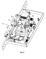
- the lock assembly in Fig. 1a comprises a plurality of latches (12, 13 and 14) movable relative to said assembly (11) in the manner to engage in suitable slots (15, 16) on the lock panel (18), an actuator mechanism for switching said plurality of latches between a locking and an unlocking positions and last but not least a transmission mechanism transferring motion to said plurality of latches (13, 14).
- a set of separate hook-shaped latches (13, 14) in the form of curvilinear projections operating reciprocally in an integral manner are employed so as to interlock with a suitable latch slot (19) laid on the frame side lock panel (20).
- Said curvilinear latches (13, 14) are designed to be operated jointly and to be rotating by way of axles (21) connected thereto.
- the hook-shaped latches (13, 14) are conventionally designed to have a curvilinear side on the outer portion of the head part, the latter extending inward in the form of a right-angled corner and forming therein a space between two blocks. One of those blocks is actually the head portion, which engages into the slot (19) on the frame side lock panel (20).
- the linearly sliding latch (12) is conventionally controlled by a handle hub in the form of a spring loaded structure actuated by the handle rotating a mechanism transferring motion to the spring loaded structure.
- the actuator mechanism of the sliding latch (12) and the transmission mechanism thereof, are widely practiced in the art and need not be further mentioned herein.
- the behavior of the sliding latch (12) with regard to the handle hub is apparent to the person skilled in the art.
- curvilinear latches (13, 14) rotation of the axles (21) so as to effect movement of the same is realized by an actuation mechanism started by insertion of a key into the keyhole (22) in the manner to advance a rotatable element (not shown), the latter commanding an arm suitable for engaging in a groove (22) to advance said actuation mechanism for curvilinear latches (13, 14).
- the function of a lock cylinder is apparent to the person in the art.
- the actuator means for the latches (13, 14) is typically comprised of a linearly guided unidirectionally sliding plate (25) with two gripping arms (29) extending to the latches' (13, 14) rotation center (21).
- the curvilinear lock bolts (13, 14) are designed to provide a single-turn 90-degree displacement ensuring engagement position into the panel slot (19) in one turn.
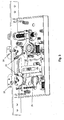
- Turning of an appropriate key in the keyhole (22) causes the axles (21) and a couple of redirection pins (23) that are guided within the latches (13, 14), to rotate said latches (13, 14) accordingly.
- Each of said pins (23) is driven back and forth between two edges of a guiding channel (24, Fig. 2 ), depending on the engaging and disengaging positions of said latches (13, 14). Synchronous movement of said redirection pin (23) together with said axle (21) leads to a full step 90-degree slip of the curvilinear latches (13, 14) in a reciprocal manner.
- each gripping arm (29) extending to each latch (13, 14) comprises an open end recess in order for laterally receiving said axles (21), whose bottom surfaces are secured to a suitable slot on at least one of the lock case sidewalls (28).
- the axles (21) are fully encircled with the exception of the recess's open end, which is preferable to limit movement thereof.
- each gripping arm (29) reciprocally advances to slip said redirection pins (23) to the channel (24) limits and further advancing of the gripping arms (29) causes the redirection pins (23) to carry said latches (13.14) around each rotation centers (21) to the full-locked position.
- the present invention features a set of special arrangements to keep the redirection pins (23) and the axles (21) away from the induced force components.
- said curvilinear latches (13, 14) are additionally provided with a plurality of pins (26) vertically projecting from the lateral surfaces of their body portions that remain within the lock case in locked position.
- the reinforcement pins (26) are the first barriers to contact the lock panel (18) in any attempt to slip said latches outwardly, that is, in the direction of the door frame. Since they are longitudinally embedded in the latch (13, 14) body in a secure manner with the head portions slightly running over the latch (13, 14) surfaces in a manner to form a sufficient contact surface with the lock panel (18) portion outside the latching slot (19), letting the latter stop the entire latch (13, 14) body moving and resisting against outward forces otherwise exerted on the redirection pins (23) and the axles (21).
- the reinforcement pins (26) are located substantially close to the lock panel (18) considering the locked position layout of the latches (13, 14). In other words, the distance of the reinforcement pins (26) to the lock panel (18) is smaller than the radius of the reinforcement pin (26) itself. More precisely, the smallest distance between a point of the reinforcement pins (26) and the lock panel (18) is smaller than the radius of the reinforcement pin (26) itself.
- reinforcement pins may also be installed on the far end of the latch (13, 14) to the lock panel (18).
- Such a pin (27) is shown in Fig. 4 .
- Such pins (27) projecting symmetrically from both surfaces of a curvilinear latch (13, 14) will further delay removal of latch (13, 14).
- the present invention proposes a locking assembly (11) comprising a plurality of regular and curvilinear latches (12, 13 and 14) movable relative to said assembly (11) in the manner to engage in suitable slots (15, 16) on the lock panel (18), actuator mechanisms for actuating said regular and curvilinear latches (12, 13 and 14) and transmission mechanisms transferring motion to said plurality of latches (13, 14), said curvilinear latches (13, 14) being provided with at least one reinforcement pin (26) projecting from the lateral surfaces of the latch (13, 14) body portions that remain within the lock case in locked position.
Landscapes
- Engineering & Computer Science (AREA)
- Structural Engineering (AREA)
- Lock And Its Accessories (AREA)
- Wing Frames And Configurations (AREA)
- Special Wing (AREA)
- Securing Of Glass Panes Or The Like (AREA)
- Control Of Vending Devices And Auxiliary Devices For Vending Devices (AREA)
Claims (2)
- Verriegelungsbaugruppe (11), umfassend einen Schieberiegel (12) und gekrümmte rotierende Riegel (13 und 14) die relativ zu der Baugruppe (11) in einer Weise beweglich sind, um in geeignete Aussparungen (15, 16) auf einer Schlossplatte (18) einzugreifen, Betätigungsmechanismen zum Betätigen des Schieberiegels (12) und der gekrümmten rotierenden Riegel (13 und 14) und Übermittelungsmechanismen, die an die Vielzahl von Riegeln (12, 13 und 14) Bewegung übertragen, dadurch gekennzeichnet, dass
die gekrümmten Riegel (13, 14) mit mindestens einem von den seitlichen Oberflächen der Rumpfteile des gekrümmten Riegels (13, 14) vorstehenden Verstärkungsstift (26) versehen sind,
wobei die seitlich von den Seitenflächen der gekrümmten Riegel (13, 14) vorstehenden Verstärkungsstifte (26) bei jedem Versuch, die Riegel (13, 14) nach außen gleiten zu lassen, eine seitliche Kontaktoberfläche mit den Teilen der Schlossplatte (18) unmittelbar über und unter der Verriegelungsaussparung (15) bilden,
wobei sich die Verstärkungsstifte (26) bezüglich der Anordnung der Riegel (13, 14) in geschlossener Position im Wesentlichen nahe zu der Schlossplatte (18) befinden. - Verriegelungsbaugruppe (11) gemäß Anspruch 1, wobei die kleinste Entfernung zwischen jedem Punkt der Verstärkungsstifte (26) und der Schlossplatte (18) kleiner ist als der Radius des Verstärkungsstiftes (26) selbst, wenn die gekrümmten rotierenden Riegel (13, 14) sich in der geschlossenen Position befinden.
Priority Applications (7)
| Application Number | Priority Date | Filing Date | Title |
|---|---|---|---|
| EP06110990.6A EP1832698B1 (de) | 2006-03-10 | 2006-03-10 | Hakenriegelverstärkungsstifte für Sicherheitsschloss |
| EA200870332A EA015020B1 (ru) | 2006-03-10 | 2007-03-08 | Запорное устройство, снабженное защелками в форме крючка с усилительными штырями |
| UAA200812018A UA90793C2 (ru) | 2006-03-10 | 2007-03-08 | Усилительные шплинты крючковой щеколды замка с секретом |
| PCT/EP2007/052193 WO2007104704A2 (en) | 2006-03-10 | 2007-03-08 | Security lock hook-shape latch reinforcement pins |
| CN2007800007244A CN101331287B (zh) | 2006-03-10 | 2007-03-08 | 安全锁的钩形锁闩的加强销 |
| MA31279A MA30329B1 (fr) | 2006-03-10 | 2008-10-09 | Tiges de renfort pour pêne a crochet de serrure de securite |
| HK09100641.4A HK1123336A1 (en) | 2006-03-10 | 2009-01-21 | Security lock hook-shape latch reinforcement pins |
Applications Claiming Priority (1)
| Application Number | Priority Date | Filing Date | Title |
|---|---|---|---|
| EP06110990.6A EP1832698B1 (de) | 2006-03-10 | 2006-03-10 | Hakenriegelverstärkungsstifte für Sicherheitsschloss |
Publications (2)
| Publication Number | Publication Date |
|---|---|
| EP1832698A1 EP1832698A1 (de) | 2007-09-12 |
| EP1832698B1 true EP1832698B1 (de) | 2015-01-28 |
Family
ID=37685699
Family Applications (1)
| Application Number | Title | Priority Date | Filing Date |
|---|---|---|---|
| EP06110990.6A Active EP1832698B1 (de) | 2006-03-10 | 2006-03-10 | Hakenriegelverstärkungsstifte für Sicherheitsschloss |
Country Status (7)
| Country | Link |
|---|---|
| EP (1) | EP1832698B1 (de) |
| CN (1) | CN101331287B (de) |
| EA (1) | EA015020B1 (de) |
| HK (1) | HK1123336A1 (de) |
| MA (1) | MA30329B1 (de) |
| UA (1) | UA90793C2 (de) |
| WO (1) | WO2007104704A2 (de) |
Families Citing this family (11)
| Publication number | Priority date | Publication date | Assignee | Title |
|---|---|---|---|---|
| CN103573038B (zh) * | 2012-07-31 | 2016-08-24 | 林永护 | 门锁 |
| CN103938929B (zh) * | 2013-01-21 | 2016-08-31 | 王力安防产品有限公司 | 联动副锁舌机构 |
| EP2924208B1 (de) * | 2014-03-26 | 2019-06-26 | Alban Giacomo S.p.A. | Gegen gewaltsames eindringen beständiges schloss |
| EP2924198A1 (de) * | 2014-03-26 | 2015-09-30 | Alban Giacomo S.p.A. | Gegen gewaltsames eindringen beständiges schloss |
| AT516517B1 (de) * | 2014-11-04 | 2016-06-15 | Roto Frank Ag | Schloss |
| CN105927059B (zh) * | 2016-06-02 | 2018-05-11 | 王力安防科技股份有限公司 | 一种具有钩舌的副锁 |
| CN105927058B (zh) * | 2016-06-02 | 2018-05-11 | 王力安防科技股份有限公司 | 具有钩锁舌的副锁 |
| DE102017208797A1 (de) | 2017-05-24 | 2018-11-29 | Geze Gmbh | Schloss für einen Flügel |
| DE102018203293B4 (de) | 2018-03-06 | 2019-12-24 | Geze Gmbh | Schloss für einen Flügel |
| CN108915367B (zh) * | 2018-06-11 | 2020-08-07 | 徐州诚凯知识产权服务有限公司 | 一种新型连接强度高的安全门锁 |
| US20210230913A1 (en) * | 2020-01-27 | 2021-07-29 | Tiffin Metal Products Co. | Compartment locking system |
Family Cites Families (6)
| Publication number | Priority date | Publication date | Assignee | Title |
|---|---|---|---|---|
| US3695068A (en) * | 1970-07-13 | 1972-10-03 | Adams Rite Mfg | Narrow stile latch-lock structure |
| CN2134463Y (zh) * | 1992-10-14 | 1993-05-26 | 北京市建筑锁厂 | 防盗门锁 |
| DE9321445U1 (de) * | 1993-02-12 | 1998-02-26 | Fliether Karl Gmbh & Co | Insbesondere an Wohnungsabschließtüren einzusetzendes Schloß, insbesondere treibstangenbetätigbares Schloß |
| GB2309996B (en) * | 1996-02-07 | 2000-09-20 | Paddock Fabr Ltd | Lock assembly |
| IT1307392B1 (it) * | 1999-09-30 | 2001-11-06 | Alban Giacomo Spa | Struttura di serratura |
| US6502435B2 (en) * | 2000-06-13 | 2003-01-07 | Yarra Ridge Pty Ltd | Locks |
-
2006
- 2006-03-10 EP EP06110990.6A patent/EP1832698B1/de active Active
-
2007
- 2007-03-08 WO PCT/EP2007/052193 patent/WO2007104704A2/en active Application Filing
- 2007-03-08 UA UAA200812018A patent/UA90793C2/ru unknown
- 2007-03-08 CN CN2007800007244A patent/CN101331287B/zh not_active Expired - Fee Related
- 2007-03-08 EA EA200870332A patent/EA015020B1/ru not_active IP Right Cessation
-
2008
- 2008-10-09 MA MA31279A patent/MA30329B1/fr unknown
-
2009
- 2009-01-21 HK HK09100641.4A patent/HK1123336A1/xx not_active IP Right Cessation
Also Published As
| Publication number | Publication date |
|---|---|
| UA90793C2 (ru) | 2010-05-25 |
| EA200870332A1 (ru) | 2009-06-30 |
| EP1832698A1 (de) | 2007-09-12 |
| HK1123336A1 (en) | 2009-06-12 |
| EA015020B1 (ru) | 2011-04-29 |
| MA30329B1 (fr) | 2009-04-01 |
| WO2007104704A2 (en) | 2007-09-20 |
| CN101331287A (zh) | 2008-12-24 |
| WO2007104704A3 (en) | 2007-11-08 |
| CN101331287B (zh) | 2011-09-07 |
Similar Documents
| Publication | Publication Date | Title |
|---|---|---|
| EP1832698B1 (de) | Hakenriegelverstärkungsstifte für Sicherheitsschloss | |
| EP1724420B1 (de) | Verbesserungen an Sicherheitsschlösser mit gemeinsamer Betätigung der hackenformigen Schliessriegel | |
| EP0004849B1 (de) | Schloss | |
| EP1862617B1 (de) | Hakenriegelverstärkungsstifte für automatisches Sicherheitsschloss | |
| CA2107408C (en) | Multipoint lock assembly for a swinging door | |
| US5878606A (en) | Door lock for swinging door | |
| JP4538001B2 (ja) | ドアー錠におけるラッチ・ボルトの錠掛けのガイド構造 | |
| AU2010202495B2 (en) | Locks | |
| EP2257681B1 (de) | Fallenanordnung für ein vorhangeschloss | |
| US7152889B2 (en) | Cable latching system | |
| EP1495202B1 (de) | Elektrisch steuerbares türschloss | |
| CA3026702C (en) | Hook bolt for door lock | |
| EP2157263B1 (de) | Verbessertes Schloss mit Verriegelung aus elliptischen Kopfabschnitten | |
| EP2171187B1 (de) | Schloss für verstärke Türen und dergleichen mit einer Wahlvorrichtung | |
| US11542726B2 (en) | Surface mounted single solenoid electric strike | |
| EA004355B1 (ru) | Дверной замок с крюкообразной задвижкой | |
| CN212927390U (zh) | 重锁装置 | |
| AU6667400A (en) | Improvements in electric strikes | |
| JP3593598B2 (ja) | 金庫の扉施錠装置 | |
| EP0574629B1 (de) | Einsteckschloss | |
| CN210127738U (zh) | 一种锁具和工具箱 | |
| IL120146A (en) | Security door | |
| KR950014820B1 (ko) | 문개폐 록크장치 | |
| AU2004100601A4 (en) | Deadlock with privacy function | |
| JPH09158572A (ja) | 開扉阻止用ポールロック錠 |
Legal Events
| Date | Code | Title | Description |
|---|---|---|---|
| PUAI | Public reference made under article 153(3) epc to a published international application that has entered the european phase |
Free format text: ORIGINAL CODE: 0009012 |
|
| AK | Designated contracting states |
Kind code of ref document: A1 Designated state(s): AT BE BG CH CY CZ DE DK EE ES FI FR GB GR HU IE IS IT LI LT LU LV MC NL PL PT RO SE SI SK TR |
|
| AX | Request for extension of the european patent |
Extension state: AL BA HR MK YU |
|
| 17P | Request for examination filed |
Effective date: 20080310 |
|
| 17Q | First examination report despatched |
Effective date: 20080409 |
|
| AKX | Designation fees paid |
Designated state(s): AT BE BG CH CY CZ DE DK EE ES FI FR GB GR HU IE IS IT LI LT LU LV MC NL PL PT RO SE SI SK TR |
|
| GRAP | Despatch of communication of intention to grant a patent |
Free format text: ORIGINAL CODE: EPIDOSNIGR1 |
|
| INTG | Intention to grant announced |
Effective date: 20141030 |
|
| GRAS | Grant fee paid |
Free format text: ORIGINAL CODE: EPIDOSNIGR3 |
|
| GRAA | (expected) grant |
Free format text: ORIGINAL CODE: 0009210 |
|
| AK | Designated contracting states |
Kind code of ref document: B1 Designated state(s): AT BE BG CH CY CZ DE DK EE ES FI FR GB GR HU IE IS IT LI LT LU LV MC NL PL PT RO SE SI SK TR |
|
| REG | Reference to a national code |
Ref country code: GB Ref legal event code: FG4D |
|
| REG | Reference to a national code |
Ref country code: CH Ref legal event code: EP |
|
| REG | Reference to a national code |
Ref country code: IE Ref legal event code: FG4D |
|
| REG | Reference to a national code |
Ref country code: DE Ref legal event code: R096 Ref document number: 602006044410 Country of ref document: DE Effective date: 20150312 |
|
| REG | Reference to a national code |
Ref country code: AT Ref legal event code: REF Ref document number: 708329 Country of ref document: AT Kind code of ref document: T Effective date: 20150315 |
|
| REG | Reference to a national code |
Ref country code: RO Ref legal event code: EPE |
|
| REG | Reference to a national code |
Ref country code: AT Ref legal event code: MK05 Ref document number: 708329 Country of ref document: AT Kind code of ref document: T Effective date: 20150128 |
|
| REG | Reference to a national code |
Ref country code: NL Ref legal event code: VDEP Effective date: 20150128 |
|
| REG | Reference to a national code |
Ref country code: LT Ref legal event code: MG4D |
|
| PG25 | Lapsed in a contracting state [announced via postgrant information from national office to epo] |
Ref country code: BG Free format text: LAPSE BECAUSE OF FAILURE TO SUBMIT A TRANSLATION OF THE DESCRIPTION OR TO PAY THE FEE WITHIN THE PRESCRIBED TIME-LIMIT Effective date: 20150428 Ref country code: ES Free format text: LAPSE BECAUSE OF FAILURE TO SUBMIT A TRANSLATION OF THE DESCRIPTION OR TO PAY THE FEE WITHIN THE PRESCRIBED TIME-LIMIT Effective date: 20150128 Ref country code: SE Free format text: LAPSE BECAUSE OF FAILURE TO SUBMIT A TRANSLATION OF THE DESCRIPTION OR TO PAY THE FEE WITHIN THE PRESCRIBED TIME-LIMIT Effective date: 20150128 Ref country code: LT Free format text: LAPSE BECAUSE OF FAILURE TO SUBMIT A TRANSLATION OF THE DESCRIPTION OR TO PAY THE FEE WITHIN THE PRESCRIBED TIME-LIMIT Effective date: 20150128 Ref country code: FI Free format text: LAPSE BECAUSE OF FAILURE TO SUBMIT A TRANSLATION OF THE DESCRIPTION OR TO PAY THE FEE WITHIN THE PRESCRIBED TIME-LIMIT Effective date: 20150128 |
|
| PG25 | Lapsed in a contracting state [announced via postgrant information from national office to epo] |
Ref country code: LV Free format text: LAPSE BECAUSE OF FAILURE TO SUBMIT A TRANSLATION OF THE DESCRIPTION OR TO PAY THE FEE WITHIN THE PRESCRIBED TIME-LIMIT Effective date: 20150128 Ref country code: AT Free format text: LAPSE BECAUSE OF FAILURE TO SUBMIT A TRANSLATION OF THE DESCRIPTION OR TO PAY THE FEE WITHIN THE PRESCRIBED TIME-LIMIT Effective date: 20150128 Ref country code: GR Free format text: LAPSE BECAUSE OF FAILURE TO SUBMIT A TRANSLATION OF THE DESCRIPTION OR TO PAY THE FEE WITHIN THE PRESCRIBED TIME-LIMIT Effective date: 20150429 Ref country code: PL Free format text: LAPSE BECAUSE OF FAILURE TO SUBMIT A TRANSLATION OF THE DESCRIPTION OR TO PAY THE FEE WITHIN THE PRESCRIBED TIME-LIMIT Effective date: 20150128 Ref country code: NL Free format text: LAPSE BECAUSE OF FAILURE TO SUBMIT A TRANSLATION OF THE DESCRIPTION OR TO PAY THE FEE WITHIN THE PRESCRIBED TIME-LIMIT Effective date: 20150128 Ref country code: IS Free format text: LAPSE BECAUSE OF FAILURE TO SUBMIT A TRANSLATION OF THE DESCRIPTION OR TO PAY THE FEE WITHIN THE PRESCRIBED TIME-LIMIT Effective date: 20150528 |
|
| REG | Reference to a national code |
Ref country code: DE Ref legal event code: R119 Ref document number: 602006044410 Country of ref document: DE |
|
| PG25 | Lapsed in a contracting state [announced via postgrant information from national office to epo] |
Ref country code: CZ Free format text: LAPSE BECAUSE OF FAILURE TO SUBMIT A TRANSLATION OF THE DESCRIPTION OR TO PAY THE FEE WITHIN THE PRESCRIBED TIME-LIMIT Effective date: 20150128 Ref country code: SK Free format text: LAPSE BECAUSE OF FAILURE TO SUBMIT A TRANSLATION OF THE DESCRIPTION OR TO PAY THE FEE WITHIN THE PRESCRIBED TIME-LIMIT Effective date: 20150128 Ref country code: LU Free format text: LAPSE BECAUSE OF FAILURE TO SUBMIT A TRANSLATION OF THE DESCRIPTION OR TO PAY THE FEE WITHIN THE PRESCRIBED TIME-LIMIT Effective date: 20150310 Ref country code: EE Free format text: LAPSE BECAUSE OF FAILURE TO SUBMIT A TRANSLATION OF THE DESCRIPTION OR TO PAY THE FEE WITHIN THE PRESCRIBED TIME-LIMIT Effective date: 20150128 Ref country code: MC Free format text: LAPSE BECAUSE OF FAILURE TO SUBMIT A TRANSLATION OF THE DESCRIPTION OR TO PAY THE FEE WITHIN THE PRESCRIBED TIME-LIMIT Effective date: 20150128 Ref country code: DK Free format text: LAPSE BECAUSE OF FAILURE TO SUBMIT A TRANSLATION OF THE DESCRIPTION OR TO PAY THE FEE WITHIN THE PRESCRIBED TIME-LIMIT Effective date: 20150128 |
|
| REG | Reference to a national code |
Ref country code: CH Ref legal event code: PL |
|
| PLBE | No opposition filed within time limit |
Free format text: ORIGINAL CODE: 0009261 |
|
| STAA | Information on the status of an ep patent application or granted ep patent |
Free format text: STATUS: NO OPPOSITION FILED WITHIN TIME LIMIT |
|
| GBPC | Gb: european patent ceased through non-payment of renewal fee |
Effective date: 20150428 |
|
| REG | Reference to a national code |
Ref country code: FR Ref legal event code: ST Effective date: 20151130 |
|
| 26N | No opposition filed |
Effective date: 20151029 |
|
| REG | Reference to a national code |
Ref country code: IE Ref legal event code: MM4A |
|
| PG25 | Lapsed in a contracting state [announced via postgrant information from national office to epo] |
Ref country code: LI Free format text: LAPSE BECAUSE OF NON-PAYMENT OF DUE FEES Effective date: 20150331 Ref country code: GB Free format text: LAPSE BECAUSE OF NON-PAYMENT OF DUE FEES Effective date: 20150428 Ref country code: CH Free format text: LAPSE BECAUSE OF NON-PAYMENT OF DUE FEES Effective date: 20150331 Ref country code: DE Free format text: LAPSE BECAUSE OF NON-PAYMENT OF DUE FEES Effective date: 20151001 Ref country code: IE Free format text: LAPSE BECAUSE OF NON-PAYMENT OF DUE FEES Effective date: 20150310 |
|
| PG25 | Lapsed in a contracting state [announced via postgrant information from national office to epo] |
Ref country code: FR Free format text: LAPSE BECAUSE OF NON-PAYMENT OF DUE FEES Effective date: 20150331 Ref country code: SI Free format text: LAPSE BECAUSE OF FAILURE TO SUBMIT A TRANSLATION OF THE DESCRIPTION OR TO PAY THE FEE WITHIN THE PRESCRIBED TIME-LIMIT Effective date: 20150128 |
|
| PG25 | Lapsed in a contracting state [announced via postgrant information from national office to epo] |
Ref country code: BE Free format text: LAPSE BECAUSE OF FAILURE TO SUBMIT A TRANSLATION OF THE DESCRIPTION OR TO PAY THE FEE WITHIN THE PRESCRIBED TIME-LIMIT Effective date: 20150128 |
|
| PGFP | Annual fee paid to national office [announced via postgrant information from national office to epo] |
Ref country code: RO Payment date: 20170310 Year of fee payment: 12 |
|
| PG25 | Lapsed in a contracting state [announced via postgrant information from national office to epo] |
Ref country code: HU Free format text: LAPSE BECAUSE OF FAILURE TO SUBMIT A TRANSLATION OF THE DESCRIPTION OR TO PAY THE FEE WITHIN THE PRESCRIBED TIME-LIMIT; INVALID AB INITIO Effective date: 20060310 |
|
| PG25 | Lapsed in a contracting state [announced via postgrant information from national office to epo] |
Ref country code: CY Free format text: LAPSE BECAUSE OF FAILURE TO SUBMIT A TRANSLATION OF THE DESCRIPTION OR TO PAY THE FEE WITHIN THE PRESCRIBED TIME-LIMIT Effective date: 20150128 |
|
| PGFP | Annual fee paid to national office [announced via postgrant information from national office to epo] |
Ref country code: IT Payment date: 20170321 Year of fee payment: 12 |
|
| PG25 | Lapsed in a contracting state [announced via postgrant information from national office to epo] |
Ref country code: PT Free format text: LAPSE BECAUSE OF FAILURE TO SUBMIT A TRANSLATION OF THE DESCRIPTION OR TO PAY THE FEE WITHIN THE PRESCRIBED TIME-LIMIT Effective date: 20150528 |
|
| PG25 | Lapsed in a contracting state [announced via postgrant information from national office to epo] |
Ref country code: RO Free format text: LAPSE BECAUSE OF NON-PAYMENT OF DUE FEES Effective date: 20180310 |
|
| PG25 | Lapsed in a contracting state [announced via postgrant information from national office to epo] |
Ref country code: IT Free format text: LAPSE BECAUSE OF NON-PAYMENT OF DUE FEES Effective date: 20180310 |
|
| PGFP | Annual fee paid to national office [announced via postgrant information from national office to epo] |
Ref country code: TR Payment date: 20210308 Year of fee payment: 16 |