EP1832537A1 - Separation and extraction device - Google Patents
Separation and extraction device Download PDFInfo
- Publication number
- EP1832537A1 EP1832537A1 EP06020402A EP06020402A EP1832537A1 EP 1832537 A1 EP1832537 A1 EP 1832537A1 EP 06020402 A EP06020402 A EP 06020402A EP 06020402 A EP06020402 A EP 06020402A EP 1832537 A1 EP1832537 A1 EP 1832537A1
- Authority
- EP
- European Patent Office
- Prior art keywords
- sheets
- sheet
- stack
- vibrator
- media
- Prior art date
- Legal status (The legal status is an assumption and is not a legal conclusion. Google has not performed a legal analysis and makes no representation as to the accuracy of the status listed.)
- Withdrawn
Links
- 238000000605 extraction Methods 0.000 title claims abstract description 105
- 238000000926 separation method Methods 0.000 title claims description 73
- 230000007246 mechanism Effects 0.000 claims abstract description 58
- 238000000034 method Methods 0.000 claims description 11
- 239000000284 extract Substances 0.000 abstract description 14
- 238000012545 processing Methods 0.000 description 11
- 238000002474 experimental method Methods 0.000 description 10
- 239000000919 ceramic Substances 0.000 description 9
- 230000007423 decrease Effects 0.000 description 7
- 230000001603 reducing effect Effects 0.000 description 6
- 230000000694 effects Effects 0.000 description 4
- 230000009467 reduction Effects 0.000 description 4
- 230000008878 coupling Effects 0.000 description 3
- 238000010168 coupling process Methods 0.000 description 3
- 238000005859 coupling reaction Methods 0.000 description 3
- 238000013461 design Methods 0.000 description 3
- 230000005484 gravity Effects 0.000 description 3
- 238000011144 upstream manufacturing Methods 0.000 description 3
- 230000004048 modification Effects 0.000 description 2
- 238000012986 modification Methods 0.000 description 2
- 230000002265 prevention Effects 0.000 description 2
- 229910000838 Al alloy Inorganic materials 0.000 description 1
- 229910000990 Ni alloy Inorganic materials 0.000 description 1
- 229910001069 Ti alloy Inorganic materials 0.000 description 1
- 239000000853 adhesive Substances 0.000 description 1
- 230000001070 adhesive effect Effects 0.000 description 1
- 230000003321 amplification Effects 0.000 description 1
- 230000033228 biological regulation Effects 0.000 description 1
- 230000008859 change Effects 0.000 description 1
- 239000012141 concentrate Substances 0.000 description 1
- 238000010276 construction Methods 0.000 description 1
- 230000008602 contraction Effects 0.000 description 1
- 230000010485 coping Effects 0.000 description 1
- 238000010586 diagram Methods 0.000 description 1
- 239000000463 material Substances 0.000 description 1
- 239000000203 mixture Substances 0.000 description 1
- 238000003199 nucleic acid amplification method Methods 0.000 description 1
- 230000001105 regulatory effect Effects 0.000 description 1
Images




Classifications
-
- B—PERFORMING OPERATIONS; TRANSPORTING
- B65—CONVEYING; PACKING; STORING; HANDLING THIN OR FILAMENTARY MATERIAL
- B65H—HANDLING THIN OR FILAMENTARY MATERIAL, e.g. SHEETS, WEBS, CABLES
- B65H3/00—Separating articles from piles
- B65H3/46—Supplementary devices or measures to assist separation or prevent double feed
- B65H3/60—Loosening articles in piles
-
- B—PERFORMING OPERATIONS; TRANSPORTING
- B65—CONVEYING; PACKING; STORING; HANDLING THIN OR FILAMENTARY MATERIAL
- B65H—HANDLING THIN OR FILAMENTARY MATERIAL, e.g. SHEETS, WEBS, CABLES
- B65H3/00—Separating articles from piles
- B65H3/46—Supplementary devices or measures to assist separation or prevent double feed
- B65H3/60—Loosening articles in piles
- B65H3/62—Loosening articles in piles by swinging, agitating, or knocking the pile
-
- B—PERFORMING OPERATIONS; TRANSPORTING
- B65—CONVEYING; PACKING; STORING; HANDLING THIN OR FILAMENTARY MATERIAL
- B65H—HANDLING THIN OR FILAMENTARY MATERIAL, e.g. SHEETS, WEBS, CABLES
- B65H3/00—Separating articles from piles
- B65H3/46—Supplementary devices or measures to assist separation or prevent double feed
- B65H3/60—Loosening articles in piles
- B65H3/64—Loosening articles in piles by vacuum apparatus
-
- B—PERFORMING OPERATIONS; TRANSPORTING
- B65—CONVEYING; PACKING; STORING; HANDLING THIN OR FILAMENTARY MATERIAL
- B65H—HANDLING THIN OR FILAMENTARY MATERIAL, e.g. SHEETS, WEBS, CABLES
- B65H2301/00—Handling processes for sheets or webs
- B65H2301/40—Type of handling process
- B65H2301/42—Piling, depiling, handling piles
- B65H2301/423—Depiling; Separating articles from a pile
- B65H2301/4234—Depiling; Separating articles from a pile assisting separation or preventing double feed
- B65H2301/42342—Depiling; Separating articles from a pile assisting separation or preventing double feed vibrating
-
- B—PERFORMING OPERATIONS; TRANSPORTING
- B65—CONVEYING; PACKING; STORING; HANDLING THIN OR FILAMENTARY MATERIAL
- B65H—HANDLING THIN OR FILAMENTARY MATERIAL, e.g. SHEETS, WEBS, CABLES
- B65H2701/00—Handled material; Storage means
- B65H2701/10—Handled articles or webs
- B65H2701/19—Specific article or web
- B65H2701/1912—Banknotes, bills and cheques or the like
Definitions
- the present invention relates to a separation and extraction device for sheets which separate a sheet in a sheet stack and extract the sheet from the sheet stack, and in particular, to a separation and extraction device which vibrates and loosens a sheet stack to separate a sheet in a sheet stack and extract a sheet from the sheet stack.
- Coping machines, printers, automatic teller machines (ATMs) in banknote processing applications, mail processing apparatuses, and the like handle sheets (paper-like media) such as print sheets, bills, copy paper, postcards, envelopes, and certificates. These machines need to extract a sheet from a stack of plural sheets.
- the machines thus comprise a separation and extraction device for sheets (paper-like media).
- a bill processing unit of an automatic teller machine repeats extracting a bill from a bundle of bills (stack of sheets) stacked in a money input and output unit or a storage safe box. The bill processing unit then inspects the extracted bill.
- the automatic teller machine comprises a separation and extraction device that always separates a bill from a bundle of bills.
- the separation and extraction devices are roughly classified into frictional type that apply a frictional force on a sheet stack to separate sheets from one another and vacuum suction type that apply both a vacuum suction force and a frictional force on a sheet stack to separate sheets from one another.
- the vacuum suction type extraction devices generally exhibit good extraction performance but disadvantageously require a large size and high costs and make much noise.
- the frictional type separation and extraction devices advantageously eliminate the need for a large size and high costs and avoid making much noise.
- an extraction mechanism such as a conveying roller or a belt depends on the frictional force of media and may cause an error during a separation and extraction operation.
- the conventional separation and extraction device exerts a strong extraction force on an extraction surface of a bundle of stacked sheets (paper-like media).
- the conventional separation and extraction device then peels off and brings out a predetermined number of sheets from the stack bundle.
- the extracted overlapping sheets are separated from one another by an overlap preventing mechanism or the like and conveyed into a sheet processing apparatus.
- the overlap preventing mechanism is based on any of various schemes.
- a common scheme separates sheets from one another by passing overlapping sheets (paper-like media) through a narrow gap.
- the following scheme is commonly adopted for ATMs, printers, and the like.
- a wide conveying and separating rollers rotating in opposite directions are arranged parallel to each other via a given gap. If overlapping sheets (paper-like media) are supplied to between these rollers, opposite forces are exerted on the sheets (paper-like media) to separate them from one another.
- a separating capability is improved by making the size of the given gap closer to the thickness of a single sheet (paper-like media).
- the mere adjustment of the given gap is often insufficient.
- a bundle of firmly adhering sheets (paper-like media) may block and lock the gap as it is, thus shutting down the apparatus. Such modification occurs frequently.
- stacked sheets are supplied from the bottom of the device along a sheet feeding board.
- the top surface of the stack is in contact with a feed roller of a feed mechanism.
- Rotation of the feed roller conveys the uppermost sheet of the stack to a device inlet port comprising an overlap preventing device.
- the overlap preventing device is composed of a pair of a forward rotating roller and a backward rotating roller arranged parallel to each other via a given gap.
- the gap is set at a value smaller than that of the thickness of two sheets.
- Ordinary vacuum suction type extraction devices use an extraction portion comprising a vacuum suction mechanism that sucks sheets. More specifically, the vacuum suction type extraction device uses a pump or compressor to draw the interior of a drum to a vacuum (negative pressure). The uppermost media of the stack is sucked into a hole formed in the periphery of the drum. The sheet is thus brought out. Specifically, stacked sheet media are fed from the bottom of the device along the sheet feeding board. The top surface of the stack is brought into contact with the vacuum suction feed roller, which then sucks and brings out the top sheet. The vacuum suction type extraction device utilizes the friction roller to exert a stronger extraction force than the frictional separation and extraction device. The vacuum suction type extraction device is thus suitable for fast processing apparatuses that can bring in sheets at high speed.
- the vacuum suction type extraction device thus employs a method of, after a predetermined number of paper-like media are peeled off from the stack bundle, using an overlap preventing mechanism or the like to separate the overlapping sheets from one another and conveying one of the resulting sheets into the apparatus.
- the vacuum suction type extraction device adopts a scheme of passing overlapping paper-like media through a narrow gap.
- the separating capability is improved by making the size of the gap closer to the thickness of single paper-like media.
- the mere adjustment of the gap is often insufficient.
- a bundle of firmly adhering paper-like media may block and lock the gap as it is, thus shutting down the apparatus. Such modification occurs frequently.
- Another overlap preventing mechanism which replaces the forward rotating roller and backward rotating roller arranged with the given gap between them.
- a feature such as a spring is used to press the backward rotating roller against the surface of a sheet to exert a pressing force on it.
- This mechanism is effective in preventing the overlapping of sheets (paper-like media) from a bundle of sheets of different thicknesses.
- this overlap preventing mechanism is readily locked if a bundle of firmly adhering sheets is brought into the overlap preventing mechanism.
- sheets such as picture postcards which have smooth surfaces and which are slightly adhesive adhere considerably firmly to one another. Consequently, when brought out from the feed roller, a bundle of such sheets is stuck between the forward rotating roller and the backward rotating roller. Even when sheared, these paper-like media are not separated from one another. This may lock the device.
- Jpn. Pat. Appln. KOKAI Publication No. 2004-002044 is known as an improved technique.
- the background art in Jpn. Pat. Appln. KOKAI Publication No. 2004-002044 abuts a bar-like vibrating member located above media that is about to be brought out, against the front surface of the media across the width to vibrate the media. This reduces the adhesion among the sheets (paper-like media) to aid an overlap preventing mechanism.
- This scheme reduces the adhesion among the bundled sheets (paper-like media) before extraction one of the sheets (paper-like media). This avoids extraction overlapping paper-like media.
- a bar-like high-frequency vibrating member with a length greater than the width of the sheets (paper-like media) is placed upstream of the feed roller to vibrate the paper-like media, while extraction one of them.
- the friction reducing mechanism employed in the overlap preventing mechanism disclosed in Jpn. Pat. Appln. KOKAI Publication No. 2004-002044 is not sufficiently effective when simply vibrating the paper-like media at a low frequency.
- the vibration frequency needs to be at least several kHz.
- the inventors' experiments show that in a vibration range from 5 to 10 kHz, the vibrating member makes a very loud noise, which affects the environment in which the device is used. Accordingly, the vibration frequency needs to be at least 10 kHz.
- a very high power of at least several hundred watts needs to be consumed to vibrate the entire vibrating member at a high frequency of at least 10 kHz, the vibrating member having a length greater than the width of the sheets.
- the power source required to drive such a large high-frequency vibrating member is very expensive. This is a major design problem.
- the inventors' experiments also show that the appropriate adhesion between the vibrating member and the sheets is very important to vibration of the stack.
- a stack of, for example, envelopes or used bills does not always have a flat surface.
- the vibrating member disclosed in Jpn. Pat. Appln. KOKAI Publication No. 2004-002044 is shaped like a plate. It is thus difficult to allow the vibrating member to adhere to the sheets all over the width.
- the vibrating member can pinpoint a contact position on the sheets but the vibration of the entire bar is only partly used. Consequently, vibration efficiency is very low. It is also possible to use more of the whole pressing force in order to allow the vibrating member to adhere to the sheets all over the width.
- this method presses the stack bundle hard from above, thus disadvantageously increasing the adhesion between the sheets. This produces the opposite effect.
- the conventional separation and extraction devices do not produce the vibrating effect required to reduce the adhesion among the stacked media.
- Experiments also show that a smaller vibration area is more effective in vibrating the media at high frequency. It has also been found that the shapes and arrangements of the conventional vibrating members present problems.
- a separation and extraction device comprising:
- a method of separating a sheet from a stack of sheets to extraction the sheet from the stack comprising:
- FIG. 1 is a schematic view showing the separation and extraction device according to the embodiment.
- FIG. 2 is a schematic diagram showing an operation performed by the separation and extraction device shown in FIG. 1 to separate and extract a sheet 11 from a sheet stack.
- the separation and extraction device shown in FIGS. 1 and 2 comprises a sheet feeding board 2 on which sheets (paper-like media) are stacked, that is, a stack 6 is placed.
- a vibrator 10 is placed on the stack 6; the vibrator 10 comprises an ultrasonic horn 14 that vibrates the stack of sheets 11, which readily adhere to one another.
- a feed roller 3 is also provided on the stack 6; the feed roller 3 serves as a feed mechanism that conveys the sheets 11.
- the sheets 11 are fed along the sheet feeding board 2 and then stacked on the sheet feeding board 2.
- the top surface of the stack 6 is in contact with the feed roller 3.
- Rotation of the feed roller 3 causes a frictional force between the feed roller 3 and the uppermost sheet (paper-like media) 11 of the stack 6 to extract this sheet.
- the sheet is then brought into a sheet processing apparatus (not shown) via a separating mechanism 7 that prevents the sheets from overlapping one another.
- the separating mechanism 7 is composed of a forward rotating roller 4 (conveying roller) that rotates in a direction in which the sheets 11 are conveyed and a backward rotating roller 5 (separating roller) which separates the overlapping sheets 11 from one another and which then returns them to the sheet feeding board 2.
- the forward rotating roller 4 and backward rotating roller 5 are arranged parallel to each other so as to have a given gap between the rollers 4 and 5.
- the gap is set at a value smaller than that of the thickness of two sheets 11.
- the feed roller 3 when rotated as shown by arrow To in FIG. 2, the feed roller 3 brings out a sheet to the separating mechanism 7, placed in the conveying direction.
- the separating mechanism 7 separates the sheets 11 fed to between the forward rotating roller 4 and the backward rotating roller 5, from one another, and conveys one of the sheets to a processing unit (not shown).
- a processing unit not shown.
- the forward rotating roller 4 is rotated as shown by arrow TO, while the backward rotating roller 5 is rotated in a direction opposite to the direction in which the forward rotating roller 4 is rotated, as shown by arrow B1.
- the uppermost sheet 11 is fed out forward by the forward rotating roller 4.
- the sheets 11 in contact with the backward rotating roller 5 are returned in the direction opposite to the conveying direction. If one sheet is supplied to the separating mechanism 7 via the feed roller 3, it is fed out forward by the forward rotating roller 4 against the rotational frictional force of the backward rotating roller 5. This is because the frictional force between the forward rotating roller 4 and the sheet 11 is stronger than that between the backward rotating roller 5 and the sheets 11.
- the above configuration avoids bringing overlapping sheets 11 into the processing apparatus.
- the forward rotating roller 4 and backward rotating roller 5 need not necessarily be arranged with the given gap between them as shown in FIGS. 1 and 2.
- a mechanism such as a spring may be used to apply a pressing force to the backward rotating roller 5 and thus to the surface of the sheets 11 conveyed by the backward rotating roller 5.
- the mechanism applying the spring force to the backward rotating roller 5 is particularly effective for overlap prevention that enables a sheet 11 to be brought out from a bundle of a mixture of sheets 11 of different thicknesses.
- the vibrator 10 contacts the uppermost sheet 11 of the stack 6 from above the stack 6.
- the vibrator 10, comprising the ultrasonic horn 14, has its leading end vibrated in a direction V0 substantially perpendicular to the surface of the stack 6.
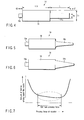
- FIGS. 1 and 2 which are simplified views of the vibrator 10, a vibrating member 12 such as the one shown in FIG. 3 is connected to the ultrasonic horn 14 shown in FIG. 4.
- the vibrating member 12 is what is called a bolt tightened vibrating member and has a piezoelectric ceramic portion 18 tightened between a pair of blocks 15 and 16 with a bolt 17.
- the piezoelectric ceramic portion 18 functions as a piezoelectric element and has electrodes 13 projecting out from the piezoelectric ceramic portion 18.
- Through-holes 15a and 18a are formed in central portions of the cylindrical block 15 and disk like piezoelectric ceramic portion 18 and are threaded so that a bolt 17 can be fitted into the through-holes 15a and 18a.
- a recessed hole 16a is formed in a central portion of piezoelectric ceramic portion 18 side of the cylindrical block 16.
- the recessed hole 16b is threaded so that the bolt 17 can be fitted in the recessed hole 16b.
- the bolt 17 is fitted and tightened in the through holes 15a and 18a in the cylindrical block 15 and disk-like piezoelectric ceramic portion 18 and in the recessed hole 16b in the cylindrical block 16. This mechanically connects the cylindrical block 15 and disk-like piezoelectric ceramic portion 16 together.
- the vibrating member 12 When the vibrating member 12 is vibrated in accordance with a driving voltage applied to the electrode 13 by the disk-like piezoelectric ceramic portion 18, the whole vibrator 10 vibrates. The resulting vibration is transmitted to a vibrating surface 16a of the cylindrical block 16.
- the piezoelectric ceramic portion 18 offers relatively small amplitude. Consequently, even if ultrasonic vibration is obtained from the vibrating surface 16a of the cylindrical block 16 and provided to the surface of the stack 6, the stack 6 cannot be provided with vibration sufficient to loosen the sheets 11. Therefore, the vibrator 12 is mechanically coupled to the ultrasonic horn 14 in order to amplify the ultrasonic vibration.
- a threaded recessed hole 16c is formed in the vibrating surface 16a of the cylindrical block 16.
- a coupling portion 19a that is fitted in the recessed hole 16c is formed on one end surface of a cylindrical block portion 19 of the ultrasonic horn 14.
- the coupling portion 19a is fitted in the recessed hole 16c to allow the cylindrical block 16 and the cylindrical block portion 19 to adhere to each other for integral coupling.
- the overall length of the cylindrical block portion 19 is specified to be one fourth of a substantially vibration wavelength ⁇ .
- An extending portion 19b extends from the other end surface of the cylindrical block portion 19; the extending portion 19b has a smaller diameter than that Sb of the cylindrical block portion 19.
- the leading end of the extending portion 19b is formed flat so as to abut against the sheets 11.
- the vibration transmitted by the cylindrical block portion 19 can have its amplitude changed by the extending portion 19b and can then be transmitted to the sheets. This is because the other end of the cylindrical block portion 19 is positioned at a vibration modal ( ⁇ /4) and because the extending portion 19b extending from the other end of the cylindrical block portion 19 has a larger or smaller diameter than the cylindrical block portion 19.
- the ultrasonic horn 14 configured as described above enables an increase in the amplitude of the vibration at the leading end to sufficiently accelerate the sheets 11.
- Reference character V2 denotes the vibration speed transmitted to the cylindrical block 16.
- Reference character V1 denotes the vibration speed output from the leading end of the ultrasonic horn 14.
- the diameter Sa of horn leading end is effectively set at about 3 to 20 mm, more preferably at 5 to 10 mm.
- a decrease in this value increases pinpoint contact pressure to allow ultrasonic waves to easily enter the sheets 11.
- this structure is likely to damage the surface of the paper-like media and is thus impractical.
- An excessively large leading end diameter results in a relative decrease in contact surface pressure to hinder ultrasonic waves from entering the sheets.
- a horn leading end diameter Sa of about 5 to 10 mm enables the easiest construction and is most effective.
- the ultrasonic horn 14 of the vibrator 10 described above is pressed against the top of the bundle (stack) of the sheets 11. This has been found to sufficiently reduce the frictional force between the leading end of the ultrasonic horn 14 and the uppermost sheet 11 and between the uppermost sheet 11 and the underlying sheet 11. It has also been found that conveying the uppermost sheet under the above conditions enables the sheets to be separated from one another without extraction overlapping sheets.
- a suitable material for the ultrasonic horn 14 is a titanium alloy which is hard and unlikely to undergo fatigue fracture.
- An aluminum alloy, a nickel alloy, or the like can also be used depending on use frequencies or conditions.
- the shape of the ultrasonic horn 14 is not limited to the larger-diameter cylindrical block and smaller-diameter cylindrical block coupled together on the same axis via a step as shown in FIG. 4.
- the diameter of the extending portion 19b may decrease gradually as shown in FIGS. 5 and 6, rather than rapidly.
- the extending portion 19b may be tapered so that its diameter gradually decreases from the cylindrical block 19 so as to draw a circular arc as shown in FIG. 5.
- the extending portion 19b may be tapered so that its diameter linearly decreases.
- the leading contact portion of the ultrasonic horn 14 is generally flat. However, the leading contact portion is likely to damage the media, offer resistance to conveyance, or be caught in a step between media such as envelopes. The leading contact portion may thus be rounded. The leading contact portion preferably has fewer recesses and protrusions on its surface so as to slide smoothly on the sheets.
- the vibrator is preferably vibrated at a vibration frequency of at least 10 KHz and contacted with the sheets 11 under a contact force of at least 200 gf and at most 1 kgf. More specifically, the vibrator 10 having the ultrasonic horn 14 with a leading end diameter of 3 to 10 mm is contacted with the stack 6 while being operated at a vibration frequency of 10 to 80 kHz and an amplitude of 5 to 50 ⁇ mp-p. It has been found that under these contact conditions, using the vibrator 10 to vibrate the surface of the stack 6 reduces the friction among the sheets 11 (paper-like media) to allow one of the sheets to be very easily brought out.
- FIG. 7 shows the relationship between the amount of friction among the paper-like media and the pressing force of the vibrator 10.
- the inventors' experiments show that if an optimum pressing force such as the one shown in FIG. 7 is applied to the paper-like media, the adhesion among the bundled sheets 11 decreases to half to one-fifth, thus excellently preventing overlapping sheets 11 from being brought out.
- the sufficiently loose sheets are conveyed until they reach the separating mechanism 7 comprising the overlap preventing function.
- the vibrator is formed like a horn to apply a spot vibration, it enables a significant reduction in the quantity of energy required to vibrate the sheets at the same amplitude compared to bar-like vibrators.
- the inventors' experiments show that the bar scheme requires at least 100W, whereas the horn-like vibrator consumes power of only 10 to 40W in order to obtain a sufficiently effective amplitude.
- the scheme of using a horn to apply a spot vibration enables the contact to concentrate at a small point.
- the size of the horn leading end can be varied depending on design.
- a practical size is such that the leading end diameter ⁇ is about 10 to 30 mm as already described. If the leading end is formed to be rectangular for an arrangement reason, the appropriate size is up to about 60 mm in a longitudinal direction.
- the sheet feeding table 2 may be placed perpendicularly to the direction of gravity so that the sheets 11 can be moved perpendicularly to the direction of gravity. Even this arrangement can produce similar effects. This arrangement prevents the weight of the stack 6 from being placed on the sheet feeding table 2.
- the sheets 11 paper-like media are "upright" with respect to the gravity when brought into the processing apparatus.
- the separation and extraction device shown in FIG. 2 may be inappropriate depending on the type of the sheets 11 (paper-like media).
- the sheets 11 paper-like media
- the bundle has a different thickness to prevent the uppermost sheet of the stack 6 from being precisely positioned. Consequently, the top surface of the bundle of sheets may strike the fixed vibrator 10 too hard or almost no contact force may be exerted.
- the efficiency has a close relationship with the contact force exerted between the surface of the vibrator 10 and the sheets 11 (paper-like media).
- a contact force exceeding the optimum range prevents a sufficient vibration from being transmitted to the sheets 11 (paper-like media).
- An excessively strong contact force may lock the leading end of the vibrator 10 to prevent its vibration.
- the surface of the sheets 11 (paper-like media) is not a perfectly flat surface but often has various recesses and protrusions.
- a bundle of bills or the like often has a markedly bent surface, which poses a similar problem.
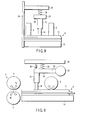
- FIGS. 8 and 9 show the separation and extraction device according to the second embodiment of the present invention, which can solve the above problem.
- the separation and extraction device comprises a rotary holding mechanism 23 (rotary pressing mechanism).
- the rotary holding mechanism 23 has a spring support structure such that the contact force of leading end of the ultrasonic horn 14 falls within the range of the optimum values shown in FIG. 7 when the vibrator 10 is rotatable in a vertical direction substantially orthogonal to the surface of the sheets and when the uppermost surface of the sheets is at a predetermined height.
- a rotating shaft 32 is rotatably fixed to a device housing 24.
- a support arm 34 is fixed to the rotating shaft 32 and has the vibrator 10 fixed substantially at its leading end so as to hang from the support arm 34. As shown in FIGS. 8 and 9, the support arm 34 is coupled to a sprig 28 and a damper 36 both fixed to a support bar 26 fixed to the housing 24.
- the spring 28 applies a spring force to the support arm 34 to press the vibrator 10, fixed to the support arm 34, against the sheets.
- the support arm 34 is rotatably supported around the rotating shaft 32, with the spring force exerted on the support arm 34. This causes the vibrator 10, fixed to the support arm 34, to be pressed against the sheets 11.
- the optimum range of the pressing force is between 200 and 1,000 gf.
- An insufficient contact force reduces the efficiency with which ultrasonic waves are transmitted to the media.
- an excessive strong contact force increase the friction between sheets thus disadvantageously hindering a single sheet from being brought out.
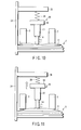
- the rotary holding mechanism 23, shown in FIGS. 8 and 9, may be replaced with a direct-acting holding mechanism 36 such as the one shown in FIGS. 10 and 11.
- the vibrator 10 may be fixed to a support block 38 replacing the support arm 34.
- the support block 38 may be fixed to the support bar 26 via the spring 28.
- the direct-acting holding mechanism 36 the sheet feeding board 12 is raised to press the stack 6 against the vibrator 10 to apply a predetermined spring force to the stack 6. That is to say, the spring of the direct-acting holding mechanism 26 is deformed to cause a contact force between the vibrator 10 and the stack 6.
- the direct-acting holding mechanism 36 allows the vibrator 10 to escape upward to prevent a possible excessively strong contact force. This enables the appropriate contact force to be maintained regardless of the position of top surface of the stack 6.
- the separation and extraction device employing the direct-acting holding mechanism 36 produces effects similar to those of the already described separation and extraction device even with a bundle of sheets such as envelopes which has a different thickness.
- the rotary holding mechanism 23 or direct-acting holding mechanism 36 quickly presses the vibrator 10 against the media surface. This enables a stable friction reducing operation to be continuously performed on the stack 6.
- the separation and extraction device can be additionally provided with a mechanism that can maintain a predetermined contact force while allowing the vibrator 10 to follow the shape of the media surface.
- an actuator such as a torque motor may be used instead of the spring that generates a pressing force as shown in FIGS. 10 to 12.
- the spring support structure shown in FIGS. 10 to 12 is simple. However, owing to the natural frequency of the spring, when the sheets 11 are conveyed at high speed, a vibrator 10 with a large mass disadvantageously cannot follow the surface of the surface of the sheets (paper-like media) at high speed. Further, the rotation range of the support arm 34 depends on and is regulated by the amount of expansion and contraction of the spring. Thus, disadvantageously, a wide rotation range is unavailable. This indicates that a significant deformation of the spring often markedly change the load.
- FIGS. 13 and 14 show a separation and extraction device according to a third embodiment of the present invention.
- the support arm 34 which supports the vibrator 10, can be moved by a torque motor 37 or the vibrator 10 is supported by a linear actuator 35.
- driving the torque motor 37 tilts the support arm 34 to allow the vibrator 10 to apply the appropriate contact force to the surface of the paper-like media.
- operating the linear actuator 35 moves the vibrator 10 in the vertical direction to apply the appropriate contact force to the surface of the paper-like media.
- the configuration shown in FIGS. 13 and 14 is not affected by the natural frequency of the spring or the regulation of movement. This enables the vibrator 10 to follow the surface of the paper-like media over a wide range at high speed and to apply a stable contact force to the paper-like media.
- FIG. 15 shows a vibrator in a separation and extraction device according to a variation of the embodiments of the present invention, as well as the shape of leading end of the vibrator 10.
- the spherical surface of leading end of the vibrator 10 prevents the vibrator 10 from being caught in a turndown part of an envelope.
- the separation and extraction device can thus more properly extract a sheet from the stack.
- FIG. 16 shows a separation and extraction device according to a variation of embodiments of the present invention.
- Even the single vibrator 10 can exert a friction reducing effect over a sufficient area of the stack 6.
- the increased speed of the device moves the top paper-like media at a higher speed, thus requiring more effective vibration.
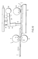
- the separation and extraction device according to the variation shown in FIG. 16 has two vibrators 10-1 and 10-2 arranged on the stack 6 along the conveying direction.
- the feed roller 3 is placed between the vibrators 10-1 and 10-2. With this arrangement, while the uppermost paper-like media is being brought out, the vibrator 10-2, located upstream in the conveying direction, can contact and vibrate the surface of the next paper-like media.
- the vibrator 10-1 located downstream in the conveying direction, vibrates the uppermost paper-like media.
- the next paper-like media 11 is vibratingly separated from the stack 6.
- the separation and extraction device shown in FIG. 16 can simultaneously vibrate the uppermost sheet 11 and the next sheet 11 to be conveyed, during a sheet extraction operation. This enables the adhesion among the bundled sheets to be reliably reduced, even if the sheet is required to be conveyed at a high transporting rate or high speed operation.
- FIG. 17 shows a separation and extraction device according to a fourth embodiment of the present invention.
- stacked sheets 11 are fed from the bottom of the device along the sheet feeding board 12.
- the top surface of the sheets 11 is in contact with the vacuum suction feed roller 3 composed of a vacuum suction drum 43. Every time the feed roller 3 rotates and its internal notch portion 46 (suction portion) comes into contact with the sheets 11, sheets 11 are sucked and their leading ends are conveyed to the separation and extraction device.
- the sheets are then brought into the processing apparatus via the separating mechanism 7.
- the separating mechanism 7 is composed of the pair of the forward rotating roller 4 and backward rotating roller 5, arranged parallel to each other with the given gap between them.
- the gap is set at the value smaller than that of thickness of two sheets.
- the vibrator 10 is in contact with the uppermost sheet of the stack 6.
- the sheets 11 are held on the sheet feeding board 12 and fed out in the extraction direction.
- the interior of the vacuum suction drum 43 is drawn to a vacuum and maintained at a negative pressure by a compressor, pump, or the like. This enables the sheet 11 to be sucked into a suction hole.
- the vacuum suction drum 43 is continuously or intermittently rotated by a motor or the like to feed the sheets 11 out into the apparatus via the separating mechanism 7 at a predetermined pitch.
- the ultrasonic horn 14 of the vibrator 10 is vibrated substantially perpendicularly to the surface of the stack 6.
- the vibration frequency, amplitude, and leading end diameter are set at 10 to 80 kHz, 5 to 50 ⁇ mp-p, and 3 to 10 mm, respectively, as already described. Under these contact conditions, vibrating the surface of the stack 6 reduces the friction among the sheets to allow one of the sheets to be very easily brought out.
- the vibrators 10 are arranged on the respective sides of the vacuum suction feed roller 3.
- the leading end of the vibrator 10 is placed to contact the stacked media 11 more sufficiently than the vacuum suction drum 43. This creates a very small gap between the vacuum suction drum 43 and the stacked media 11.
- the stack 11 is pressed, by the sheet feeding board 12, against a extract portion including a suction portion 46 of the vacuum suction feed roller 3.
- the stack 6 is brought into contact with the ultrasonic horn 14 before with the vacuum suction drum 43.
- the surface of extract portion of the extract drum 43 is not flush with the leading end of the ultrasonic horn 14.
- the shift amount is set between, for example, 0.1 and 5 mm.
- the inventors' experiments show that the efficiency of friction reduction based on vibration has a close relationship with the contact force exerted between the surface of the vibrating member and the media.
- a contact force exceeding the optimum range prevents a sufficient vibration from being transmitted to the media.
- An excessively strong contact force may lock the leading end of the vibrating member to prevent its vibration.
- the separation and extraction device shown in FIG. 17 allows the contact force between the ultrasonic horn 14 and the paper-like media 11 to be appropriately controlled while a sheet 11 is being brought out. Ultrasonic waves can be more efficiently applied within the optimum range of pressure. This enables a sufficient reduction in the adhesion among the initially adhering sheets in the stack 6.
- FIGS. 20 and 21 show a separation and extraction device according to a fifth embodiment of the present invention.
- the separation and extraction device shown in FIGS. 20 and 21 has the ultrasonic horns 14 arranged at the respective ends of the vacuum suction drum 43 and each having a leading end inclined toward the drum as shown in FIGS. 20 and 21.
- Each of the inclined ultrasonic horns 14 vibrates to generate an advancing component acting parallel to the surface of the sheets. This deforms the uppermost sheet 11 into a shape which is more readily sucked by the vacuum suction drum 43 and which varies depending on the flexibility of the sheets 11, as shown in FIG. 21.
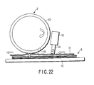
- FIG. 22 is a separation and extraction device according to a fifth embodiment of the present invention.
- the separation and extraction device shown in FIG. 22 has the ultrasonic horn 14 inclined, rearward with respect to the drum 43 in the extraction direction (downstream of the drum 43 in the conveying direction).
- the sheets can be deformed depending on the flexibility of the sheets 11 as is the case with the device shown in FIG. 21.
- the ultrasonic horn is placed rearward in the sheet extraction direction. Consequently, after the uppermost sheet is brought out from the stack 6 and passes through the contact portion of the ultrasonic horn 14, the next sheet 11 to be brought out can be deformed as shown in FIG. 23. A sufficient time can be provided to deform the sheet to enable sheets to be consecutively brought out at a higher speed.
- the separation and extraction devices of the present invention enable a reduction in the energy required for vibration.
- the separation and extraction devices can use the very efficient vibrator with reduced power consumption to reliably separatively extract a sheet from the stack without being affected by the shape of the sheets.
- a separation and extraction device that can very efficiently separate and extract a sheet from a stack with reduced power consumption and without being affected by the shape of the sheets.
Landscapes
- Engineering & Computer Science (AREA)
- Mechanical Engineering (AREA)
- Sheets, Magazines, And Separation Thereof (AREA)
Abstract
Description
- The present invention relates to a separation and extraction device for sheets which separate a sheet in a sheet stack and extract the sheet from the sheet stack, and in particular, to a separation and extraction device which vibrates and loosens a sheet stack to separate a sheet in a sheet stack and extract a sheet from the sheet stack.
- Coping machines, printers, automatic teller machines (ATMs) in banknote processing applications, mail processing apparatuses, and the like handle sheets (paper-like media) such as print sheets, bills, copy paper, postcards, envelopes, and certificates. These machines need to extract a sheet from a stack of plural sheets. The machines thus comprise a separation and extraction device for sheets (paper-like media). By way of example, a bill processing unit of an automatic teller machine repeats extracting a bill from a bundle of bills (stack of sheets) stacked in a money input and output unit or a storage safe box. The bill processing unit then inspects the extracted bill. Accordingly, the automatic teller machine comprises a separation and extraction device that always separates a bill from a bundle of bills.
- For conventional separation and extraction devices that separate a sheet and extract the sheet (paper-like media) from a sheet stack, it is most important to precisely extract each sheet into the apparatus while preventing overlapping sheets from being introduced at a time. Stacked sheets (paper-like media) are in close contact with one another for a long time and thus often stick to one another. Thus, each sheet needs to be separated and extracted, reliably.
- The separation and extraction devices are roughly classified into frictional type that apply a frictional force on a sheet stack to separate sheets from one another and vacuum suction type that apply both a vacuum suction force and a frictional force on a sheet stack to separate sheets from one another. The vacuum suction type extraction devices generally exhibit good extraction performance but disadvantageously require a large size and high costs and make much noise. The frictional type separation and extraction devices advantageously eliminate the need for a large size and high costs and avoid making much noise. However, an extraction mechanism such as a conveying roller or a belt depends on the frictional force of media and may cause an error during a separation and extraction operation.
- To separate adhering sheets from one another, the conventional separation and extraction device exerts a strong extraction force on an extraction surface of a bundle of stacked sheets (paper-like media). The conventional separation and extraction device then peels off and brings out a predetermined number of sheets from the stack bundle. After the extraction, the extracted overlapping sheets are separated from one another by an overlap preventing mechanism or the like and conveyed into a sheet processing apparatus.
- The overlap preventing mechanism is based on any of various schemes. A common scheme separates sheets from one another by passing overlapping sheets (paper-like media) through a narrow gap. For example, the following scheme is commonly adopted for ATMs, printers, and the like. A wide conveying and separating rollers rotating in opposite directions are arranged parallel to each other via a given gap. If overlapping sheets (paper-like media) are supplied to between these rollers, opposite forces are exerted on the sheets (paper-like media) to separate them from one another. With this scheme, a separating capability is improved by making the size of the given gap closer to the thickness of a single sheet (paper-like media). However, normally, the mere adjustment of the given gap is often insufficient. A bundle of firmly adhering sheets (paper-like media) may block and lock the gap as it is, thus shutting down the apparatus. Such modification occurs frequently.
- More specifically, in ordinary frictional separation and extraction devices, stacked sheets are supplied from the bottom of the device along a sheet feeding board. The top surface of the stack is in contact with a feed roller of a feed mechanism. Rotation of the feed roller conveys the uppermost sheet of the stack to a device inlet port comprising an overlap preventing device. The overlap preventing device is composed of a pair of a forward rotating roller and a backward rotating roller arranged parallel to each other via a given gap. The gap is set at a value smaller than that of the thickness of two sheets. When overlapping sheets are passing through these rollers, the lower backward rotating roller returns all these sheets other than the uppermost one toward the bundle of sheets to prevent them from being brought into the apparatus. This prevents overlapping sheets from being brought into the apparatus as they are.
- Ordinary vacuum suction type extraction devices use an extraction portion comprising a vacuum suction mechanism that sucks sheets. More specifically, the vacuum suction type extraction device uses a pump or compressor to draw the interior of a drum to a vacuum (negative pressure). The uppermost media of the stack is sucked into a hole formed in the periphery of the drum. The sheet is thus brought out. Specifically, stacked sheet media are fed from the bottom of the device along the sheet feeding board. The top surface of the stack is brought into contact with the vacuum suction feed roller, which then sucks and brings out the top sheet. The vacuum suction type extraction device utilizes the friction roller to exert a stronger extraction force than the frictional separation and extraction device. The vacuum suction type extraction device is thus suitable for fast processing apparatuses that can bring in sheets at high speed.
- However, even with the vacuum suction type extraction device, the stacked paper-like media often stick to one another after a long, close contact. Even if a strong extraction force is exerted on the extraction surface in order to separate the paper-like media from one another, overlapping sheets are often brought into the apparatus. The vacuum suction type extraction device thus employs a method of, after a predetermined number of paper-like media are peeled off from the stack bundle, using an overlap preventing mechanism or the like to separate the overlapping sheets from one another and conveying one of the resulting sheets into the apparatus.
- Like the frictional type separation and extraction device, the vacuum suction type extraction device adopts a scheme of passing overlapping paper-like media through a narrow gap. As is the case with the overlap preventing mechanism of the frictional type separation and extraction device, the separating capability is improved by making the size of the gap closer to the thickness of single paper-like media. However, the mere adjustment of the gap is often insufficient. A bundle of firmly adhering paper-like media may block and lock the gap as it is, thus shutting down the apparatus. Such modification occurs frequently.
- Another overlap preventing mechanism is known which replaces the forward rotating roller and backward rotating roller arranged with the given gap between them. In this mechanism, a feature such as a spring is used to press the backward rotating roller against the surface of a sheet to exert a pressing force on it. This mechanism is effective in preventing the overlapping of sheets (paper-like media) from a bundle of sheets of different thicknesses.
- As described above, this overlap preventing mechanism is readily locked if a bundle of firmly adhering sheets is brought into the overlap preventing mechanism. For example, when stacked and pressed, sheets such as picture postcards which have smooth surfaces and which are slightly adhesive adhere considerably firmly to one another. Consequently, when brought out from the feed roller, a bundle of such sheets is stuck between the forward rotating roller and the backward rotating roller. Even when sheared, these paper-like media are not separated from one another. This may lock the device.
- Jpn. Pat. Appln. KOKAI Publication
No. 2004-002044 No. 2004-002044 - The friction reducing mechanism employed in the overlap preventing mechanism disclosed in Jpn. Pat. Appln. KOKAI Publication
No. 2004-002044 - The inventors' experiments also show that the appropriate adhesion between the vibrating member and the sheets is very important to vibration of the stack. A stack of, for example, envelopes or used bills does not always have a flat surface. However, the vibrating member disclosed in Jpn. Pat. Appln. KOKAI Publication
No. 2004-002044 - As described above, the conventional separation and extraction devices do not produce the vibrating effect required to reduce the adhesion among the stacked media. Experiments also show that a smaller vibration area is more effective in vibrating the media at high frequency. It has also been found that the shapes and arrangements of the conventional vibrating members present problems.
- For the background art disclosed in Jpn. Pat. Appln. KOKAI Publication
No. 2004-002044 - According to an aspect of the present invention, there is provided a separation and extraction device comprising:
- a supporting unit configured to support a stack of sheets;
- a vibrator which is in contact with a sheet surface of the stack, configured to apply a spot vibration on the sheet surface of the stack at high frequency to separate the sheets of the stack;
- a sheet extraction mechanism configured to extract a sheet or sheets from the sheet surface of the stack and convey the sheet or sheets sequentially; and
- a separating mechanism configured to separate one sheet from the other sheet or sheets and convey the one sheet.
- According to an another aspect of the present invention, there is provided a method of separating a sheet from a stack of sheets to extraction the sheet from the stack, comprising:
- supporting a stack of sheets;
- applying a spot vibration on a sheet surface of the stack at high frequency to separate the sheet or sheets of the stack;
- extracting a sheet or sheets from the sheet surface of the stack and conveying the sheet or sheets sequentially;
- separating one of the sheet or sheets from the other sheet or sheets and convey the one of the sheet.
- The invention can be more fully understood from the following detailed description when taken in conjunction with the accompanying drawings, in which:
- FIG. 1 is a side view schematically showing a separation and extraction device according to an embodiment;
- FIG. 2 is a side view schematically showing a sheet separation and extraction operation of the separation and extraction device shown in FIG. 1;
- FIG. 3 is a side view schematically showing a vibrating member of a vibrator shown in FIGS. 1 and 2;
- FIG. 4 is a side view schematically showing an ultrasonic horn of the vibrator shown in FIGS. 1 and 2;
- FIG. 5 is a side view schematically showing a variation of the ultrasonic horn shown in FIG. 4;
- FIG. 6 is a side view schematically showing another variation of the ultrasonic horn shown in FIG. 4;
- FIG. 7 is a graph showing the relationship between the pressing force of the vibrator shown in FIGS. 1 and 2 and the amount of friction among the sheets;
- FIG. 8 is a front view schematically showing a separation and extraction device according to a second embodiment of the present invention;
- FIG. 9 is a side view schematically showing the separation and extraction device shown in FIG. 8;
- FIG. 10 is a front view schematically showing a separation and extraction device according to a third embodiment of the present invention;
- FIG. 11 is a side view of the separation and extraction device shown in FIG. 10;
- FIG. 12 is a side view schematically showing a variation of the separation and extraction device shown in FIGS. 8 and 9;
- FIG. 13 is a side view schematically showing a variation of the separation and extraction device shown in FIGS. 8 and 9;
- FIG. 14 is a side view schematically showing a variation of the separation and extraction device shown in FIGS. 10 and 11;
- FIG. 15 is a side view schematically showing a variation of an ultrasonic horn in the separation and extraction device shown in FIGS. 8 to 14;
- FIG. 16 is a side view schematically showing another variation of the separation and extraction device shown in FIGS. 8 and 9;
- FIG. 17 is a side view schematically showing a separation and extraction device according to a fourth embodiment of the present invention;
- FIG. 18 is a front view of the separation and extraction device shown in FIG. 17;
- FIG. 19 is a side view schematically showing a sheet separation and extraction operation of the separation and extraction device shown in FIGS. 17 and 18;
- FIG. 20 is a front view schematically showing a separation and extraction device according to a fifth embodiment of the present invention;
- FIG. 21 is a front view schematically showing a sheet separation and extraction operation of the separation and extraction device shown in FIG. 20; and
- FIGS. 22 and 23 are side views schematically showing a sheet separation and extraction operation of the separation and extraction device shown in FIG. 21.
- With reference to the drawings, description will be given of a separation and extraction device according to an embodiment of the present invention.
- FIG. 1 is a schematic view showing the separation and extraction device according to the embodiment. FIG. 2 is a schematic diagram showing an operation performed by the separation and extraction device shown in FIG. 1 to separate and extract a
sheet 11 from a sheet stack. - The separation and extraction device shown in FIGS. 1 and 2 comprises a
sheet feeding board 2 on which sheets (paper-like media) are stacked, that is, astack 6 is placed. Avibrator 10 is placed on thestack 6; thevibrator 10 comprises anultrasonic horn 14 that vibrates the stack ofsheets 11, which readily adhere to one another. Afeed roller 3 is also provided on thestack 6; thefeed roller 3 serves as a feed mechanism that conveys thesheets 11. Thesheets 11 are fed along thesheet feeding board 2 and then stacked on thesheet feeding board 2. The top surface of thestack 6 is in contact with thefeed roller 3. Rotation of thefeed roller 3 causes a frictional force between thefeed roller 3 and the uppermost sheet (paper-like media) 11 of thestack 6 to extract this sheet. The sheet is then brought into a sheet processing apparatus (not shown) via aseparating mechanism 7 that prevents the sheets from overlapping one another. - The
separating mechanism 7 is composed of a forward rotating roller 4 (conveying roller) that rotates in a direction in which thesheets 11 are conveyed and a backward rotating roller 5 (separating roller) which separates the overlappingsheets 11 from one another and which then returns them to thesheet feeding board 2. The forwardrotating roller 4 and backwardrotating roller 5 are arranged parallel to each other so as to have a given gap between therollers sheets 11. Thus, when the overlappingsheets 11 are passing through therollers stack 6 by the backwardrotating roller 5, located at the bottom of theseparating mechanism 7. This prevents these sheets from being brought into the apparatus. - In the separation and extraction device shown in FIG. 1, when rotated as shown by arrow To in FIG. 2, the
feed roller 3 brings out a sheet to theseparating mechanism 7, placed in the conveying direction. Theseparating mechanism 7 separates thesheets 11 fed to between the forwardrotating roller 4 and the backwardrotating roller 5, from one another, and conveys one of the sheets to a processing unit (not shown). In theseparating mechanism 7, shown in FIG. 2, to feed thesheet 11 in the conveying direction, the forwardrotating roller 4 is rotated as shown by arrow TO, while the backwardrotating roller 5 is rotated in a direction opposite to the direction in which the forwardrotating roller 4 is rotated, as shown by arrow B1. Accordingly, if a plurality ofsheets 11 are supplied to theseparating mechanism 7 via thefeed roller 3, theuppermost sheet 11 is fed out forward by the forwardrotating roller 4. Thesheets 11 in contact with the backwardrotating roller 5 are returned in the direction opposite to the conveying direction. If one sheet is supplied to theseparating mechanism 7 via thefeed roller 3, it is fed out forward by the forwardrotating roller 4 against the rotational frictional force of the backwardrotating roller 5. This is because the frictional force between the forwardrotating roller 4 and thesheet 11 is stronger than that between the backwardrotating roller 5 and thesheets 11. - The above configuration avoids bringing overlapping
sheets 11 into the processing apparatus. The forwardrotating roller 4 and backwardrotating roller 5 need not necessarily be arranged with the given gap between them as shown in FIGS. 1 and 2. A mechanism such as a spring may be used to apply a pressing force to the backwardrotating roller 5 and thus to the surface of thesheets 11 conveyed by the backwardrotating roller 5. The mechanism applying the spring force to the backwardrotating roller 5 is particularly effective for overlap prevention that enables asheet 11 to be brought out from a bundle of a mixture ofsheets 11 of different thicknesses. - As shown in FIGS. 1 and 2, the
vibrator 10 contacts theuppermost sheet 11 of thestack 6 from above thestack 6. Thevibrator 10, comprising theultrasonic horn 14, has its leading end vibrated in a direction V0 substantially perpendicular to the surface of thestack 6. - In FIGS. 1 and 2, which are simplified views of the
vibrator 10, a vibratingmember 12 such as the one shown in FIG. 3 is connected to theultrasonic horn 14 shown in FIG. 4. As shown in FIG. 3, the vibratingmember 12 is what is called a bolt tightened vibrating member and has a piezoelectricceramic portion 18 tightened between a pair ofblocks bolt 17. The piezoelectricceramic portion 18 functions as a piezoelectric element and haselectrodes 13 projecting out from the piezoelectricceramic portion 18. Through-holes cylindrical block 15 and disk like piezoelectricceramic portion 18 and are threaded so that abolt 17 can be fitted into the through-holes hole 16a is formed in a central portion of piezoelectricceramic portion 18 side of thecylindrical block 16. The recessedhole 16b is threaded so that thebolt 17 can be fitted in the recessedhole 16b. Thebolt 17 is fitted and tightened in the throughholes cylindrical block 15 and disk-like piezoelectricceramic portion 18 and in the recessedhole 16b in thecylindrical block 16. This mechanically connects thecylindrical block 15 and disk-like piezoelectricceramic portion 16 together. - When the vibrating
member 12 is vibrated in accordance with a driving voltage applied to theelectrode 13 by the disk-like piezoelectricceramic portion 18, thewhole vibrator 10 vibrates. The resulting vibration is transmitted to a vibratingsurface 16a of thecylindrical block 16. The piezoelectricceramic portion 18 offers relatively small amplitude. Consequently, even if ultrasonic vibration is obtained from the vibratingsurface 16a of thecylindrical block 16 and provided to the surface of thestack 6, thestack 6 cannot be provided with vibration sufficient to loosen thesheets 11. Therefore, thevibrator 12 is mechanically coupled to theultrasonic horn 14 in order to amplify the ultrasonic vibration. - To allow the
ultrasonic horn 14, shown in FIG. 4, to be mechanically coupled, a threaded recessedhole 16c is formed in the vibratingsurface 16a of thecylindrical block 16. Acoupling portion 19a that is fitted in the recessedhole 16c is formed on one end surface of acylindrical block portion 19 of theultrasonic horn 14. Thecoupling portion 19a is fitted in the recessedhole 16c to allow thecylindrical block 16 and thecylindrical block portion 19 to adhere to each other for integral coupling. The overall length of thecylindrical block portion 19 is specified to be one fourth of a substantially vibration wavelength λ. An extendingportion 19b extends from the other end surface of thecylindrical block portion 19; the extendingportion 19b has a smaller diameter than that Sb of thecylindrical block portion 19. The leading end of the extendingportion 19b is formed flat so as to abut against thesheets 11. In theultrasonic horn 14, the vibration transmitted by thecylindrical block portion 19 can have its amplitude changed by the extendingportion 19b and can then be transmitted to the sheets. This is because the other end of thecylindrical block portion 19 is positioned at a vibration modal (λ/4) and because the extendingportion 19b extending from the other end of thecylindrical block portion 19 has a larger or smaller diameter than thecylindrical block portion 19. - With the
ultrasonic horn 14 configured as described above, the vibration speed at the leading end of theultrasonic horn 14 is amplified so that V1/V2 = Sb/Sa. Theultrasonic horn 14 configured as described above enables an increase in the amplitude of the vibration at the leading end to sufficiently accelerate thesheets 11. Reference character V2 denotes the vibration speed transmitted to thecylindrical block 16. Reference character V1 denotes the vibration speed output from the leading end of theultrasonic horn 14. - Experiments were carried out with the diameter Sa of the leading end set at 5 mm and with the 20-mm
ultrasonic horn 14 coupled to the 20 x 60-mm vibrating member 12. The experiments show that the vibration amplification rate Sb/Sa of theultrasonic horn 14 is doubled. The experiments also show that a friction reducing effect is highest at Sa = 5 mm. This indicates that the increased diameter of leading end of theultrasonic horn 14 results in relative enhancement of in-plane vibration components, thus hindering axial vibration components contributing to the vibration. In contrast, since theultrasonic horn 14 is in contact with thesheets 11, contact pressure decreases with increasing diameter Sa under a fixed pressing force. This avoids possible damage to the media. It has been confirmed that the friction reducing effect is not exerted only by the vibratingmember 12 free from theultrasonic horn 14. In practical design, the diameter Sa of horn leading end is effectively set at about 3 to 20 mm, more preferably at 5 to 10 mm. A decrease in this value increases pinpoint contact pressure to allow ultrasonic waves to easily enter thesheets 11. However, this structure is likely to damage the surface of the paper-like media and is thus impractical. An excessively large leading end diameter results in a relative decrease in contact surface pressure to hinder ultrasonic waves from entering the sheets. Experiments show that a horn leading end diameter Sa of about 5 to 10 mm enables the easiest construction and is most effective. - The
ultrasonic horn 14 of thevibrator 10 described above is pressed against the top of the bundle (stack) of thesheets 11. This has been found to sufficiently reduce the frictional force between the leading end of theultrasonic horn 14 and theuppermost sheet 11 and between theuppermost sheet 11 and theunderlying sheet 11. It has also been found that conveying the uppermost sheet under the above conditions enables the sheets to be separated from one another without extraction overlapping sheets. - A suitable material for the
ultrasonic horn 14 is a titanium alloy which is hard and unlikely to undergo fatigue fracture. An aluminum alloy, a nickel alloy, or the like can also be used depending on use frequencies or conditions. The shape of theultrasonic horn 14 is not limited to the larger-diameter cylindrical block and smaller-diameter cylindrical block coupled together on the same axis via a step as shown in FIG. 4. The diameter of the extendingportion 19b may decrease gradually as shown in FIGS. 5 and 6, rather than rapidly. In other words, the extendingportion 19b may be tapered so that its diameter gradually decreases from thecylindrical block 19 so as to draw a circular arc as shown in FIG. 5. Alternatively, the extendingportion 19b may be tapered so that its diameter linearly decreases. - The leading contact portion of the
ultrasonic horn 14 is generally flat. However, the leading contact portion is likely to damage the media, offer resistance to conveyance, or be caught in a step between media such as envelopes. The leading contact portion may thus be rounded. The leading contact portion preferably has fewer recesses and protrusions on its surface so as to slide smoothly on the sheets. - The vibrator is preferably vibrated at a vibration frequency of at least 10 KHz and contacted with the
sheets 11 under a contact force of at least 200 gf and at most 1 kgf. More specifically, thevibrator 10 having theultrasonic horn 14 with a leading end diameter of 3 to 10 mm is contacted with thestack 6 while being operated at a vibration frequency of 10 to 80 kHz and an amplitude of 5 to 50 µmp-p. It has been found that under these contact conditions, using thevibrator 10 to vibrate the surface of thestack 6 reduces the friction among the sheets 11 (paper-like media) to allow one of the sheets to be very easily brought out. FIG. 7 shows the relationship between the amount of friction among the paper-like media and the pressing force of thevibrator 10. The inventors' experiments show that if an optimum pressing force such as the one shown in FIG. 7 is applied to the paper-like media, the adhesion among the bundledsheets 11 decreases to half to one-fifth, thus excellently preventing overlappingsheets 11 from being brought out. - As shown in FIG. 2, the sufficiently loose sheets (paper-like sheets) are conveyed until they reach the
separating mechanism 7 comprising the overlap preventing function. This prevents the device from, for example, being locked when a bundle of adhesively overlapping sheets is brought out from the bundle. If the vibrator is formed like a horn to apply a spot vibration, it enables a significant reduction in the quantity of energy required to vibrate the sheets at the same amplitude compared to bar-like vibrators. The inventors' experiments show that the bar scheme requires at least 100W, whereas the horn-like vibrator consumes power of only 10 to 40W in order to obtain a sufficiently effective amplitude. During vibration, the scheme of using a horn to apply a spot vibration enables the contact to concentrate at a small point. This makes it possible to increase the efficiency with which vibration propagates to the sheets (paper-like media) 11. The size of the horn leading end can be varied depending on design. A practical size is such that the leading end diameter φ is about 10 to 30 mm as already described. If the leading end is formed to be rectangular for an arrangement reason, the appropriate size is up to about 60 mm in a longitudinal direction. - In the arrangement shown in FIG. 2, the sheet feeding table 2 may be placed perpendicularly to the direction of gravity so that the
sheets 11 can be moved perpendicularly to the direction of gravity. Even this arrangement can produce similar effects. This arrangement prevents the weight of thestack 6 from being placed on the sheet feeding table 2. The sheets 11 (paper-like media) are "upright" with respect to the gravity when brought into the processing apparatus. - With reference to FIGS. 8 and 9, description will be given of a separation and extraction device according to a second embodiment of the present invention.
- The separation and extraction device shown in FIG. 2 may be inappropriate depending on the type of the sheets 11 (paper-like media). For example, if the sheets 11 (paper-like media) are envelopes or the like, the bundle has a different thickness to prevent the uppermost sheet of the
stack 6 from being precisely positioned. Consequently, the top surface of the bundle of sheets may strike the fixedvibrator 10 too hard or almost no contact force may be exerted. As shown in FIG. 7, the efficiency has a close relationship with the contact force exerted between the surface of thevibrator 10 and the sheets 11 (paper-like media). A contact force exceeding the optimum range prevents a sufficient vibration from being transmitted to the sheets 11 (paper-like media). An excessively strong contact force may lock the leading end of thevibrator 10 to prevent its vibration. The surface of the sheets 11 (paper-like media) is not a perfectly flat surface but often has various recesses and protrusions. A bundle of bills or the like often has a markedly bent surface, which poses a similar problem. - FIGS. 8 and 9 show the separation and extraction device according to the second embodiment of the present invention, which can solve the above problem. As shown in FIGS. 8 and 9, the separation and extraction device comprises a rotary holding mechanism 23 (rotary pressing mechanism). The
rotary holding mechanism 23 has a spring support structure such that the contact force of leading end of theultrasonic horn 14 falls within the range of the optimum values shown in FIG. 7 when thevibrator 10 is rotatable in a vertical direction substantially orthogonal to the surface of the sheets and when the uppermost surface of the sheets is at a predetermined height. Specifically, as shown in FIG. 9, a rotatingshaft 32 is rotatably fixed to adevice housing 24. Asupport arm 34 is fixed to therotating shaft 32 and has thevibrator 10 fixed substantially at its leading end so as to hang from thesupport arm 34. As shown in FIGS. 8 and 9, thesupport arm 34 is coupled to asprig 28 and adamper 36 both fixed to asupport bar 26 fixed to thehousing 24. Thespring 28 applies a spring force to thesupport arm 34 to press thevibrator 10, fixed to thesupport arm 34, against the sheets. - In the
rotary holding mechanism 23, shown in FIGS. 8 and 9, thesupport arm 34 is rotatably supported around the rotatingshaft 32, with the spring force exerted on thesupport arm 34. This causes thevibrator 10, fixed to thesupport arm 34, to be pressed against thesheets 11. The optimum range of the pressing force is between 200 and 1,000 gf. An insufficient contact force reduces the efficiency with which ultrasonic waves are transmitted to the media. However, an excessive strong contact force increase the friction between sheets thus disadvantageously hindering a single sheet from being brought out. - The above values are thus experimentally determined. The
rotary holding mechanism 23, shown in FIGS. 8 and 9, may be replaced with a direct-actingholding mechanism 36 such as the one shown in FIGS. 10 and 11. Specifically, thevibrator 10 may be fixed to asupport block 38 replacing thesupport arm 34. Thesupport block 38 may be fixed to thesupport bar 26 via thespring 28. With the direct-actingholding mechanism 36, thesheet feeding board 12 is raised to press thestack 6 against thevibrator 10 to apply a predetermined spring force to thestack 6. That is to say, the spring of the direct-actingholding mechanism 26 is deformed to cause a contact force between thevibrator 10 and thestack 6. For example, even if the top surface of the stack bundle slightly rises as it is, the direct-actingholding mechanism 36 allows thevibrator 10 to escape upward to prevent a possible excessively strong contact force. This enables the appropriate contact force to be maintained regardless of the position of top surface of thestack 6. As shown in FIGS. 10 and 11, the separation and extraction device employing the direct-actingholding mechanism 36 produces effects similar to those of the already described separation and extraction device even with a bundle of sheets such as envelopes which has a different thickness. - As shown in FIG. 12, even if a step is created on the surface of the
stack 6 while a sheet 11 (paper-like media) is being brought out, therotary holding mechanism 23 or direct-actingholding mechanism 36 quickly presses thevibrator 10 against the media surface. This enables a stable friction reducing operation to be continuously performed on thestack 6. The separation and extraction device can be additionally provided with a mechanism that can maintain a predetermined contact force while allowing thevibrator 10 to follow the shape of the media surface. - As shown in FIGS. 13 and 14, an actuator such as a torque motor may be used instead of the spring that generates a pressing force as shown in FIGS. 10 to 12. The spring support structure shown in FIGS. 10 to 12 is simple. However, owing to the natural frequency of the spring, when the
sheets 11 are conveyed at high speed, avibrator 10 with a large mass disadvantageously cannot follow the surface of the surface of the sheets (paper-like media) at high speed. Further, the rotation range of thesupport arm 34 depends on and is regulated by the amount of expansion and contraction of the spring. Thus, disadvantageously, a wide rotation range is unavailable. This indicates that a significant deformation of the spring often markedly change the load. - FIGS. 13 and 14 show a separation and extraction device according to a third embodiment of the present invention. The
support arm 34, which supports thevibrator 10, can be moved by atorque motor 37 or thevibrator 10 is supported by alinear actuator 35. In the separation and extraction device shown in FIG. 13, driving thetorque motor 37 tilts thesupport arm 34 to allow thevibrator 10 to apply the appropriate contact force to the surface of the paper-like media. In the separation and extraction device shown in FIG. 12, operating thelinear actuator 35 moves thevibrator 10 in the vertical direction to apply the appropriate contact force to the surface of the paper-like media. The configuration shown in FIGS. 13 and 14 is not affected by the natural frequency of the spring or the regulation of movement. This enables thevibrator 10 to follow the surface of the paper-like media over a wide range at high speed and to apply a stable contact force to the paper-like media. - FIG. 15 shows a vibrator in a separation and extraction device according to a variation of the embodiments of the present invention, as well as the shape of leading end of the
vibrator 10. The spherical surface of leading end of thevibrator 10 prevents thevibrator 10 from being caught in a turndown part of an envelope. The separation and extraction device can thus more properly extract a sheet from the stack. - FIG. 16 shows a separation and extraction device according to a variation of embodiments of the present invention. Even the
single vibrator 10 can exert a friction reducing effect over a sufficient area of thestack 6. However, the increased speed of the device moves the top paper-like media at a higher speed, thus requiring more effective vibration. The separation and extraction device according to the variation shown in FIG. 16 has two vibrators 10-1 and 10-2 arranged on thestack 6 along the conveying direction. Thefeed roller 3 is placed between the vibrators 10-1 and 10-2. With this arrangement, while the uppermost paper-like media is being brought out, the vibrator 10-2, located upstream in the conveying direction, can contact and vibrate the surface of the next paper-like media. The vibrator 10-1, located downstream in the conveying direction, vibrates the uppermost paper-like media. The vibrator 10-2, located upstream in the conveying direction, vibrates the paper-like media 11 located under the paper-like media being conveyed and which is to be conveyed next. The next paper-like media 11 is vibratingly separated from thestack 6. The separation and extraction device shown in FIG. 16 can simultaneously vibrate theuppermost sheet 11 and thenext sheet 11 to be conveyed, during a sheet extraction operation. This enables the adhesion among the bundled sheets to be reliably reduced, even if the sheet is required to be conveyed at a high transporting rate or high speed operation. - FIG. 17 shows a separation and extraction device according to a fourth embodiment of the present invention. In the separation and extraction device shown in FIG. 17, stacked
sheets 11 are fed from the bottom of the device along thesheet feeding board 12. The top surface of thesheets 11 is in contact with the vacuumsuction feed roller 3 composed of avacuum suction drum 43. Every time thefeed roller 3 rotates and its internal notch portion 46 (suction portion) comes into contact with thesheets 11,sheets 11 are sucked and their leading ends are conveyed to the separation and extraction device. The sheets are then brought into the processing apparatus via theseparating mechanism 7. Theseparating mechanism 7 is composed of the pair of the forwardrotating roller 4 and backwardrotating roller 5, arranged parallel to each other with the given gap between them. The gap is set at the value smaller than that of thickness of two sheets. Thus, when the overlappingsheets 11 are passing through therollers stack 6 by the backwardrotating roller 5 and thus prevented from being brought into the apparatus. This prevents overlapping sheets from being brought into the apparatus. - In the separation and extraction device shown in FIG. 17, the
vibrator 10 is in contact with the uppermost sheet of thestack 6. Thesheets 11 are held on thesheet feeding board 12 and fed out in the extraction direction. The interior of thevacuum suction drum 43 is drawn to a vacuum and maintained at a negative pressure by a compressor, pump, or the like. This enables thesheet 11 to be sucked into a suction hole. Thevacuum suction drum 43 is continuously or intermittently rotated by a motor or the like to feed thesheets 11 out into the apparatus via theseparating mechanism 7 at a predetermined pitch. - As shown in FIG. 17, with its leading end in contact with the surface of the
stack 6, theultrasonic horn 14 of thevibrator 10 is vibrated substantially perpendicularly to the surface of thestack 6. The vibration frequency, amplitude, and leading end diameter are set at 10 to 80 kHz, 5 to 50 µmp-p, and 3 to 10 mm, respectively, as already described. Under these contact conditions, vibrating the surface of thestack 6 reduces the friction among the sheets to allow one of the sheets to be very easily brought out. - As shown in FIGS. 18 and 19, the
vibrators 10 are arranged on the respective sides of the vacuumsuction feed roller 3. The leading end of thevibrator 10 is placed to contact thestacked media 11 more sufficiently than thevacuum suction drum 43. This creates a very small gap between thevacuum suction drum 43 and the stackedmedia 11. Thestack 11 is pressed, by thesheet feeding board 12, against a extract portion including asuction portion 46 of the vacuumsuction feed roller 3. Thestack 6 is brought into contact with theultrasonic horn 14 before with thevacuum suction drum 43. The surface of extract portion of theextract drum 43 is not flush with the leading end of theultrasonic horn 14. There is a small difference in height (shift amount) between the surface of the extract portion and the leading end of theultrasonic horn 14. The shift amount is set between, for example, 0.1 and 5 mm. - As already described with reference to FIG. 7, the inventors' experiments show that the efficiency of friction reduction based on vibration has a close relationship with the contact force exerted between the surface of the vibrating member and the media. A contact force exceeding the optimum range prevents a sufficient vibration from being transmitted to the media. An excessively strong contact force may lock the leading end of the vibrating member to prevent its vibration. The separation and extraction device shown in FIG. 17 allows the contact force between the
ultrasonic horn 14 and the paper-like media 11 to be appropriately controlled while asheet 11 is being brought out. Ultrasonic waves can be more efficiently applied within the optimum range of pressure. This enables a sufficient reduction in the adhesion among the initially adhering sheets in thestack 6. Under these conditions, a negative pressure from the vacuum suction drum on the media allows the uppermost media to be easily separated from the remaining paper-like media. The uppermost media is deformed and sucked by thevacuum suction drum 43 as shown in FIG. 19. Then, rotating thedrum 43 feeds the uppermost paper-like media 11 out into the apparatus, while preventing other overlapping media from being brought into the apparatus. - With the separation and extraction device shown in FIGS. 17 to 19, when the
sheets 11 are sucked by thevacuum suction drum 43 before ultrasonic waves are transmitted to thesheets 11, a extraction operation is undesirably started before an adhesion reducing operation is. Thus, theultrasonic horn 14 comes into contact with the paper-like media before the extract portion does. The amount by which theultrasonic horn 14 is shifted from thevacuum suction drum 43 desirably corresponds to a distance short enough to allow the suction force of the drum to suck the single media. This makes it possible to stabilize the quick separation carried out by theultrasonic horn 14 andvacuum suction drum 43. - FIGS. 20 and 21 show a separation and extraction device according to a fifth embodiment of the present invention. The separation and extraction device shown in FIGS. 20 and 21 has the
ultrasonic horns 14 arranged at the respective ends of thevacuum suction drum 43 and each having a leading end inclined toward the drum as shown in FIGS. 20 and 21. Each of the inclinedultrasonic horns 14 vibrates to generate an advancing component acting parallel to the surface of the sheets. This deforms theuppermost sheet 11 into a shape which is more readily sucked by thevacuum suction drum 43 and which varies depending on the flexibility of thesheets 11, as shown in FIG. 21. - FIG. 22 is a separation and extraction device according to a fifth embodiment of the present invention. The separation and extraction device shown in FIG. 22 has the
ultrasonic horn 14 inclined, rearward with respect to thedrum 43 in the extraction direction (downstream of thedrum 43 in the conveying direction). With the arrangement shown in FIG. 22, the sheets can be deformed depending on the flexibility of thesheets 11 as is the case with the device shown in FIG. 21. In this arrangement, the ultrasonic horn is placed rearward in the sheet extraction direction. Consequently, after the uppermost sheet is brought out from thestack 6 and passes through the contact portion of theultrasonic horn 14, thenext sheet 11 to be brought out can be deformed as shown in FIG. 23. A sufficient time can be provided to deform the sheet to enable sheets to be consecutively brought out at a higher speed. - The separation and extraction devices of the present invention enable a reduction in the energy required for vibration. The separation and extraction devices can use the very efficient vibrator with reduced power consumption to reliably separatively extract a sheet from the stack without being affected by the shape of the sheets.
- As described above, according to an embodiment of the present invention, there is provided a separation and extraction device that can very efficiently separate and extract a sheet from a stack with reduced power consumption and without being affected by the shape of the sheets.
Claims (17)
- A separation and extraction device comprising:a supporting unit (2, 12) configured to support a stack (6) of sheets (11);a sheet extraction mechanism (3) configured to extract a sheet or sheets (11) from the sheet surface of the stack (6) and convey the sheet or sheets (11) sequentially; anda separating mechanism (7) configured to separate one sheet (11) from the other sheet or sheets (11) and convey the one sheet (11), characterized by further comprising:a vibrator (10) which is in contact with a sheet surface of the stack (6), configured to apply a spot vibration on the sheet surface of the stack (6) at high frequency to separate the sheets (11) of the stack (6);.
- The device according to claim 1, characterized in that the sheet extraction mechanism (3) includes a feeding mechanism (3) configured to feed the sheet (11) by a frictional force applied between the sheet surface of the stack (6) and the feeding mechanism (3).
- The device according to claim 1, characterized in that the vibrator (10) comes into contact with the surface of the sheets (11) under a predetermined contact force to vibrate the sheets (11) in a direction substantially orthogonal to the surface of the sheets (11).
- The device according to claim 1, characterized by further comprising a holding mechanism (23, 24, 26, 28, 32, 34, 36, 37) configured to hold the vibrator (10) so that the vibrator (10) can be moved in the direction substantially orthogonal to the surface of the sheets (11), the holding mechanism (23, 24, 26, 28, 32, 34, 36, 37) contacting the vibrator (10) with the surface of the sheets (11) under the predetermined contact force.
- The device according to claim 1, characterized in that the vibrator (10) is vibrated at a vibration frequency of at least 10 KHz.
- The device according to claim 1, characterized in that the vibrator (10) is contacted with the sheets (11) under a contact force of at least 200 gf and at most 1 kgf.
- The device according to claim 1, characterized in that the extraction mechanism (3) includes a suction mechanism (43, 46) configured to suck the sheet or sheets (11) of the stack (6) by a vacuum suction force to extract the sheet or sheets (11).
- The device according to claim 6, characterized in that the suction mechanism has a suction portion (46) which sucks the sheets (11), the vibrator (10) has a leading end which is placed closer to the sheet surface of the stack (6) than the suction portion, and the vibrator (10) and the suction mechanism are arranged so that a difference of 0.1 to 5 mm is set between the leading end and the suction portion.
- The device according to claim 7, characterized in that the suction portion (46) sequentially comes into contact with the sheet surface of the stack (6) to extract the sheet (11), and the leading end of the vibrator (10) comes into contact with the sheet surface of the stack (6) before the suction portion (46) is operated.
- The device according to claim 1, characterized in that the vibrator (10) is inclined in a direction in which the sheet (11) is extracted.
- A method of separating a sheet (11) from a stack (6) of sheets (11) to extraction the sheet (11) from the stack (6), characterized by comprising:supporting a stack (6) of sheets (11);applying a spot vibration on a sheet surface of the stack (6) at high frequency to separate the sheet or sheets (11) of the stack (6);extracting a sheet or sheets (11) from the sheet surface of the stack (6) and conveying the sheet or sheets (11) sequentially;separating one of the sheet or sheets (11) from the other sheet or sheets (11) and convey the one of the sheet (11).
- The method according to claim 11, characterized in that the sheet extracting includes a feeding the sheet (11) by a frictional force.
- The method according to claim 11, characterized in that the applying the spot vibrating includes applying a predetermined contact force to the surface of the sheets (11) and vibrating the sheets (11) in a direction substantially orthogonal to the surface of the sheets (11).
- The method according to claim 11, characterized in that the vibration has a vibration frequency of at least 10 KHz.
- The method according to claim 11, characterized in that the vibration is applied to the sheets (11) under a contact force of at least 200 gf and at most 1 kgf.
- The method according to claim 11, characterized in that the extracting includes sucking the sheet or sheets (11) of the stack (6) by a vacuum suction force to extract the sheet or sheets (11).
- The method to claim 16, characterized in that the vibration is applied to the stack (6) in a direction inclined to the sheet surface.
Applications Claiming Priority (1)
| Application Number | Priority Date | Filing Date | Title |
|---|---|---|---|
| JP2006059608A JP2007238206A (en) | 2006-03-06 | 2006-03-06 | Separation take-out device |
Publications (1)
| Publication Number | Publication Date |
|---|---|
| EP1832537A1 true EP1832537A1 (en) | 2007-09-12 |
Family
ID=38093512
Family Applications (1)
| Application Number | Title | Priority Date | Filing Date |
|---|---|---|---|
| EP06020402A Withdrawn EP1832537A1 (en) | 2006-03-06 | 2006-09-28 | Separation and extraction device |
Country Status (3)
| Country | Link |
|---|---|
| US (1) | US7694957B2 (en) |
| EP (1) | EP1832537A1 (en) |
| JP (1) | JP2007238206A (en) |
Cited By (4)
| Publication number | Priority date | Publication date | Assignee | Title |
|---|---|---|---|---|
| EP2077244A3 (en) * | 2008-01-04 | 2011-12-07 | Ricoh Company, Ltd. | Sheet conveying apparatus and image forming apparatus |
| EP2096057A3 (en) * | 2008-02-29 | 2011-12-28 | Kabushiki Kaisha Toshiba | Apparatus for separating and extracting paper leaves |
| TWI721507B (en) * | 2019-07-23 | 2021-03-11 | 藍德工業股份有限公司 | Stripping and carrying device for sheet |
| TWI734524B (en) * | 2020-06-12 | 2021-07-21 | 藍德工業股份有限公司 | Transfer device with separation mechanism |
Families Citing this family (14)
| Publication number | Priority date | Publication date | Assignee | Title |
|---|---|---|---|---|
| JP4127708B2 (en) * | 2006-05-23 | 2008-07-30 | 株式会社東芝 | Separation and removal device for paper-like media |
| JP4302148B2 (en) * | 2007-03-12 | 2009-07-22 | 株式会社東芝 | Paper sheet separating device, paper sheet separating and extracting device, paper sheet processing device, paper sheet separating method, and paper sheet separating and extracting method |
| US8371006B2 (en) * | 2009-03-17 | 2013-02-12 | Raytheon Company | Rotary mechanical vibration mechanism |
| WO2011013230A1 (en) | 2009-07-30 | 2011-02-03 | 株式会社 東芝 | Bundle state detection system and separation/take-out device |
| US20110121015A1 (en) * | 2009-09-18 | 2011-05-26 | Steven Krengel | Paper-Towel Apparatus for Reusing Non-Structured Paperless Paper-Towels |
| JP2012071902A (en) * | 2010-09-27 | 2012-04-12 | Toshiba Corp | Medium conveyor apparatus and control method |
| US11220409B2 (en) * | 2011-10-31 | 2022-01-11 | Ncr Corporation | Single item removal |
| JP5870338B2 (en) * | 2012-03-21 | 2016-02-24 | 旭精工株式会社 | Sheet-like product dispensing device |
| JP6016105B2 (en) * | 2012-11-20 | 2016-10-26 | 大日本印刷株式会社 | Metal thin plate dimension measuring apparatus and metal thin plate dimension measuring method |
| JP2014231431A (en) | 2013-05-30 | 2014-12-11 | 株式会社東芝 | Separating and taking out device, and separating and taking out method |
| EP2962968B1 (en) * | 2014-07-01 | 2017-05-10 | Wincor Nixdorf International GmbH | Device for separating sheet goods |
| CN108792677A (en) * | 2018-06-26 | 2018-11-13 | 重庆宏正包装印务有限公司 | A kind of automatic paper-changing printing equipment |
| CN110672514A (en) * | 2019-10-25 | 2020-01-10 | 上海应用技术大学 | Metal clad sheet peeling test device |
| KR102953903B1 (en) * | 2022-07-13 | 2026-04-16 | 주식회사 엘지에너지솔루션 | Adsorption device |
Citations (4)
| Publication number | Priority date | Publication date | Assignee | Title |
|---|---|---|---|---|
| US3545741A (en) * | 1966-04-29 | 1970-12-08 | Baeuerle Gmbh Mathias | Collator with sheet feeders assisted by vibration |
| EP0905067A1 (en) * | 1997-09-11 | 1999-03-31 | W.P. Mechanics N.V. | A method and a device for removing a sheet from a stack of sheets |
| EP0978466A2 (en) * | 1998-08-05 | 2000-02-09 | Francotyp-Postalia Aktiengesellschaft & Co. | Apparatus for the separation of documents |
| DE19943029A1 (en) * | 1998-10-08 | 2000-04-13 | Heidelberger Druckmasch Ag | Paper handling system for use with printing machine loosens topmost sheet of paper from stack using sound source and side blower |
Family Cites Families (15)
| Publication number | Priority date | Publication date | Assignee | Title |
|---|---|---|---|---|
| BE791354A (en) * | 1971-11-15 | 1973-03-01 | True Data Corp | CARD HANDLING DEVICE |
| AT353221B (en) * | 1973-11-21 | 1979-11-12 | Gao Ges Automation Org | DEVICE FOR SINGLEIZING PAPER SHEETS AND THE LIKE. |
| JPS6217653A (en) | 1985-07-15 | 1987-01-26 | Sumitomo Metal Ind Ltd | Method for ultrasonic flaw detection of welded pipe |
| JPS6217653U (en) * | 1985-07-16 | 1987-02-02 | ||
| US4955598A (en) * | 1987-09-28 | 1990-09-11 | Fuji Xerox Co., Ltd. | Paper feeding apparatus |
| JPH0648602A (en) * | 1992-07-28 | 1994-02-22 | Nasuka:Kk | Ultrasonic thin plate peeling device |
| JPH06329287A (en) * | 1993-03-26 | 1994-11-29 | Matsushita Electric Works Ltd | Separation method for resin board |
| JPH0769466A (en) * | 1993-09-03 | 1995-03-14 | Seikosha Co Ltd | Recording medium feeder |
| US5967507A (en) * | 1997-04-14 | 1999-10-19 | Xerox Corporation | Automatic document handler having non-relative motion vacuum corrugating device |
| JPH11106075A (en) * | 1997-10-06 | 1999-04-20 | Nikon Corp | Recording sheet holding device and paper feeding device |
| US5934662A (en) * | 1997-10-14 | 1999-08-10 | Xerox Corporation | Bottom sheet separator-feeder with sheet stack levitation |
| JP2002356240A (en) * | 2001-05-31 | 2002-12-10 | Ricoh Co Ltd | Sheet feeding method, sheet feeding apparatus for executing the same, and image forming apparatus |
| JP2003290811A (en) * | 2002-03-29 | 2003-10-14 | Jfe Steel Kk | Method and apparatus for stabilizing pass line of metal strip |
| JP2004002044A (en) | 2003-08-20 | 2004-01-08 | Mitsubishi Heavy Ind Ltd | Paper feeder for paper sheet press |
| JP4127708B2 (en) * | 2006-05-23 | 2008-07-30 | 株式会社東芝 | Separation and removal device for paper-like media |
-
2006
- 2006-03-06 JP JP2006059608A patent/JP2007238206A/en active Pending
- 2006-09-27 US US11/535,733 patent/US7694957B2/en not_active Expired - Fee Related
- 2006-09-28 EP EP06020402A patent/EP1832537A1/en not_active Withdrawn
Patent Citations (4)
| Publication number | Priority date | Publication date | Assignee | Title |
|---|---|---|---|---|
| US3545741A (en) * | 1966-04-29 | 1970-12-08 | Baeuerle Gmbh Mathias | Collator with sheet feeders assisted by vibration |
| EP0905067A1 (en) * | 1997-09-11 | 1999-03-31 | W.P. Mechanics N.V. | A method and a device for removing a sheet from a stack of sheets |
| EP0978466A2 (en) * | 1998-08-05 | 2000-02-09 | Francotyp-Postalia Aktiengesellschaft & Co. | Apparatus for the separation of documents |
| DE19943029A1 (en) * | 1998-10-08 | 2000-04-13 | Heidelberger Druckmasch Ag | Paper handling system for use with printing machine loosens topmost sheet of paper from stack using sound source and side blower |
Cited By (4)
| Publication number | Priority date | Publication date | Assignee | Title |
|---|---|---|---|---|
| EP2077244A3 (en) * | 2008-01-04 | 2011-12-07 | Ricoh Company, Ltd. | Sheet conveying apparatus and image forming apparatus |
| EP2096057A3 (en) * | 2008-02-29 | 2011-12-28 | Kabushiki Kaisha Toshiba | Apparatus for separating and extracting paper leaves |
| TWI721507B (en) * | 2019-07-23 | 2021-03-11 | 藍德工業股份有限公司 | Stripping and carrying device for sheet |
| TWI734524B (en) * | 2020-06-12 | 2021-07-21 | 藍德工業股份有限公司 | Transfer device with separation mechanism |
Also Published As
| Publication number | Publication date |
|---|---|
| US7694957B2 (en) | 2010-04-13 |
| US20070205551A1 (en) | 2007-09-06 |
| JP2007238206A (en) | 2007-09-20 |
Similar Documents
| Publication | Publication Date | Title |
|---|---|---|
| US7694957B2 (en) | Separation and extraction device | |
| US7708268B2 (en) | Separator and feeder with vibrator for sheets of paper medium | |
| CN1248861C (en) | Device for preventing double-paper feed in printer | |
| EP2096057A2 (en) | Apparatus for separating and extracting paper leaves | |
| US6585253B1 (en) | Feeder with vibrating separating device | |
| US5704607A (en) | Sheet feed and presenting assembly | |
| JP4127409B2 (en) | Paper feeder for image forming equipment | |
| CN1096268A (en) | Separate methods and devices | |
| JP4284313B2 (en) | Separation take-out device | |
| JP2009227399A (en) | Separation/takeout device | |
| EP0645328B1 (en) | Sheet feed and presenting assemblies | |
| JP2008239335A (en) | High frequency vibration separating and taking out device | |
| KR100601859B1 (en) | Paper Feeding Device of Image Forming Device | |
| JPH0616271A (en) | Paper feeder | |
| JP2614929B2 (en) | Paper sheet peeling device | |
| JPH05213468A (en) | Device and method for sorting paper sheet | |
| JPH05201571A (en) | Sheet separating and feeding mechanism | |
| JPH10203657A (en) | Paper feeder | |
| JP2949534B2 (en) | Paper feeder | |
| JPH06286890A (en) | Sheet feeder | |
| KR20040061074A (en) | Automatic paper feeding apparatus for printer | |
| TW200827184A (en) | The business machine and the paper feeding mechanism thereof | |
| JP2009173387A (en) | Sheet loading mechanism, paper feeder, image formation device | |
| JPH01313224A (en) | Automatic paper feed mechanism | |
| JPH04112141A (en) | Paper guide device of paper feeding device |
Legal Events
| Date | Code | Title | Description |
|---|---|---|---|
| PUAI | Public reference made under article 153(3) epc to a published international application that has entered the european phase |
Free format text: ORIGINAL CODE: 0009012 |
|
| 17P | Request for examination filed |
Effective date: 20060928 |
|
| AK | Designated contracting states |
Kind code of ref document: A1 Designated state(s): AT BE BG CH CY CZ DE DK EE ES FI FR GB GR HU IE IS IT LI LT LU LV MC NL PL PT RO SE SI SK TR |
|
| AX | Request for extension of the european patent |
Extension state: AL BA HR MK YU |
|
| 17Q | First examination report despatched |
Effective date: 20071219 |
|
| AKX | Designation fees paid |
Designated state(s): DE FR GB |
|
| GRAP | Despatch of communication of intention to grant a patent |
Free format text: ORIGINAL CODE: EPIDOSNIGR1 |
|
| RTI1 | Title (correction) |
Free format text: SEPARATION AND EXTRACTION DEVICE AND METHOD |
|
| STAA | Information on the status of an ep patent application or granted ep patent |
Free format text: STATUS: THE APPLICATION IS DEEMED TO BE WITHDRAWN |
|
| 18D | Application deemed to be withdrawn |
Effective date: 20110712 |