JP2012071902A - Medium conveyor apparatus and control method - Google Patents
Medium conveyor apparatus and control method Download PDFInfo
- Publication number
- JP2012071902A JP2012071902A JP2010215837A JP2010215837A JP2012071902A JP 2012071902 A JP2012071902 A JP 2012071902A JP 2010215837 A JP2010215837 A JP 2010215837A JP 2010215837 A JP2010215837 A JP 2010215837A JP 2012071902 A JP2012071902 A JP 2012071902A
- Authority
- JP
- Japan
- Prior art keywords
- medium
- unit
- air
- thin plate
- cooling
- Prior art date
- Legal status (The legal status is an assumption and is not a legal conclusion. Google has not performed a legal analysis and makes no representation as to the accuracy of the status listed.)
- Pending
Links
Images


Classifications
-
- B—PERFORMING OPERATIONS; TRANSPORTING
- B65—CONVEYING; PACKING; STORING; HANDLING THIN OR FILAMENTARY MATERIAL
- B65G—TRANSPORT OR STORAGE DEVICES, e.g. CONVEYORS FOR LOADING OR TIPPING, SHOP CONVEYOR SYSTEMS OR PNEUMATIC TUBE CONVEYORS
- B65G69/00—Auxiliary measures taken, or devices used, in connection with loading or unloading
- B65G69/20—Auxiliary treatments, e.g. aerating, heating, humidifying, deaerating, cooling, de-watering or drying, during loading or unloading; Loading or unloading in a fluid medium other than air
-
- B—PERFORMING OPERATIONS; TRANSPORTING
- B65—CONVEYING; PACKING; STORING; HANDLING THIN OR FILAMENTARY MATERIAL
- B65G—TRANSPORT OR STORAGE DEVICES, e.g. CONVEYORS FOR LOADING OR TIPPING, SHOP CONVEYOR SYSTEMS OR PNEUMATIC TUBE CONVEYORS
- B65G59/00—De-stacking of articles
- B65G59/02—De-stacking from the top of the stack
-
- B—PERFORMING OPERATIONS; TRANSPORTING
- B65—CONVEYING; PACKING; STORING; HANDLING THIN OR FILAMENTARY MATERIAL
- B65H—HANDLING THIN OR FILAMENTARY MATERIAL, e.g. SHEETS, WEBS, CABLES
- B65H3/00—Separating articles from piles
- B65H3/46—Supplementary devices or measures to assist separation or prevent double feed
- B65H3/48—Air blast acting on edges of, or under, articles
-
- B—PERFORMING OPERATIONS; TRANSPORTING
- B65—CONVEYING; PACKING; STORING; HANDLING THIN OR FILAMENTARY MATERIAL
- B65H—HANDLING THIN OR FILAMENTARY MATERIAL, e.g. SHEETS, WEBS, CABLES
- B65H3/00—Separating articles from piles
- B65H3/46—Supplementary devices or measures to assist separation or prevent double feed
- B65H3/60—Loosening articles in piles
-
- B—PERFORMING OPERATIONS; TRANSPORTING
- B65—CONVEYING; PACKING; STORING; HANDLING THIN OR FILAMENTARY MATERIAL
- B65H—HANDLING THIN OR FILAMENTARY MATERIAL, e.g. SHEETS, WEBS, CABLES
- B65H2301/00—Handling processes for sheets or webs
- B65H2301/40—Type of handling process
- B65H2301/42—Piling, depiling, handling piles
- B65H2301/423—Depiling; Separating articles from a pile
- B65H2301/4234—Depiling; Separating articles from a pile assisting separation or preventing double feed
- B65H2301/42342—Depiling; Separating articles from a pile assisting separation or preventing double feed vibrating
-
- B—PERFORMING OPERATIONS; TRANSPORTING
- B65—CONVEYING; PACKING; STORING; HANDLING THIN OR FILAMENTARY MATERIAL
- B65H—HANDLING THIN OR FILAMENTARY MATERIAL, e.g. SHEETS, WEBS, CABLES
- B65H2301/00—Handling processes for sheets or webs
- B65H2301/50—Auxiliary process performed during handling process
- B65H2301/51—Modifying a characteristic of handled material
- B65H2301/514—Modifying physical properties
- B65H2301/5144—Cooling
-
- B—PERFORMING OPERATIONS; TRANSPORTING
- B65—CONVEYING; PACKING; STORING; HANDLING THIN OR FILAMENTARY MATERIAL
- B65H—HANDLING THIN OR FILAMENTARY MATERIAL, e.g. SHEETS, WEBS, CABLES
- B65H2515/00—Physical entities not provided for in groups B65H2511/00 or B65H2513/00
- B65H2515/40—Temperature; Thermal conductivity
-
- B—PERFORMING OPERATIONS; TRANSPORTING
- B65—CONVEYING; PACKING; STORING; HANDLING THIN OR FILAMENTARY MATERIAL
- B65H—HANDLING THIN OR FILAMENTARY MATERIAL, e.g. SHEETS, WEBS, CABLES
- B65H2701/00—Handled material; Storage means
- B65H2701/10—Handled articles or webs
- B65H2701/17—Nature of material
- B65H2701/176—Cardboard
-
- B—PERFORMING OPERATIONS; TRANSPORTING
- B65—CONVEYING; PACKING; STORING; HANDLING THIN OR FILAMENTARY MATERIAL
- B65H—HANDLING THIN OR FILAMENTARY MATERIAL, e.g. SHEETS, WEBS, CABLES
- B65H2701/00—Handled material; Storage means
- B65H2701/10—Handled articles or webs
- B65H2701/19—Specific article or web
- B65H2701/1912—Banknotes, bills and cheques or the like
Landscapes
- Engineering & Computer Science (AREA)
- Mechanical Engineering (AREA)
- Sheets, Magazines, And Separation Thereof (AREA)
- Feeding Of Articles By Means Other Than Belts Or Rollers (AREA)
Abstract
【課題】搬送される薄板状の媒体に働く摩擦力をより軽減すること。
【解決手段】実施形態によれば、振動部と、冷却部と、搬送部と、温度検出部と、制御部とを備える。振動部は、搬送対象となる薄板状媒体に振動を加える。冷却部は、前記薄板状媒体に近接する空気を冷却する。搬送部は、前記薄板状媒体を搬送させる。温度検出部は、前記薄板状媒体の周囲の温度を検出する。制御部は、前記温度検出部により検出された温度に基づいて前記冷却部を制御する。
【選択図】図1A friction force acting on a thin plate-like medium to be conveyed is further reduced.
According to an embodiment, a vibration unit, a cooling unit, a transport unit, a temperature detection unit, and a control unit are provided. The vibration unit applies vibration to the thin plate medium to be transported. The cooling unit cools the air adjacent to the thin plate medium. The transport unit transports the thin plate medium. The temperature detection unit detects a temperature around the thin plate medium. The control unit controls the cooling unit based on the temperature detected by the temperature detection unit.
[Selection] Figure 1
Description
本発明の実施形態は、薄板状の媒体を搬送する媒体搬送装置及び制御方法に関する。 Embodiments described herein relate generally to a medium transport apparatus and a control method for transporting a thin plate-shaped medium.
搬送機構において搬送される媒体に働く摩擦力を高周波振動により軽減する技術が知られている。 A technique for reducing frictional force acting on a medium conveyed in a conveyance mechanism by high-frequency vibration is known.
一つの例として、有価証券などの紙状媒体を取り扱う省力化機器に関し、積層された束から媒体を1枚ずつ次々と取り出す機構において摩擦力を減少させる技術がある。この技術では、紙状媒体を高周波加振する際に振動子の押圧力を制御することより、最上面の媒体とその下に接する2枚めの媒体との間の摩擦力を減少させる。 As an example, there is a technique for reducing the frictional force in a mechanism for taking out media one by one from a stack of bundles regarding a labor-saving device that handles paper-like media such as securities. In this technique, the frictional force between the uppermost medium and the second medium in contact therewith is reduced by controlling the pressing force of the vibrator when the paper-like medium is vibrated at high frequency.
他の例として、フィルム製造装置など連続する紙状媒体を扱うウェブ搬送機器に関し、ウェブと搬送機構との摺動抵抗を低減させる技術がある。この技術では、搬送機構を振動させ、搬送機構とウェブとの接触状態を制御することにより、摺動抵抗を低減させる。 As another example, there is a technique for reducing the sliding resistance between the web and the transport mechanism with respect to a web transport device that handles continuous paper-like media such as a film manufacturing apparatus. In this technique, the sliding resistance is reduced by vibrating the conveying mechanism and controlling the contact state between the conveying mechanism and the web.
搬送機構において搬送される薄板状の媒体に働く摩擦力をより軽減する技術が望まれている。 There is a demand for a technique for further reducing the frictional force acting on a thin plate-like medium conveyed by the conveyance mechanism.
本実施形態は、搬送される薄板状の媒体に働く摩擦力をより軽減することの可能な媒体搬送装置及び制御方法を提供することを目的とする。 An object of the present embodiment is to provide a medium conveying apparatus and a control method capable of further reducing the frictional force acting on a thin plate-like medium to be conveyed.
実施形態によれば、振動部と、冷却部と、搬送部と、温度検出部と、制御部とを備える。振動部は、搬送対象となる薄板状媒体に振動を加える。冷却部は、前記薄板状媒体に近接する空気を冷却する。搬送部は、前記薄板状媒体を搬送させる。温度検出部は、前記薄板状媒体の周囲の温度を検出する。制御部は、前記温度検出部により検出された温度に基づいて前記冷却部を制御する。 According to the embodiment, the vibration unit, the cooling unit, the transport unit, the temperature detection unit, and the control unit are provided. The vibration unit applies vibration to the thin plate medium to be transported. The cooling unit cools the air adjacent to the thin plate medium. The transport unit transports the thin plate medium. The temperature detection unit detects a temperature around the thin plate medium. The control unit controls the cooling unit based on the temperature detected by the temperature detection unit.
以下、図面を参照しながら本発明の実施形態に係る媒体搬送装置について詳細に説明する。なお、以下の実施形態では、同一の番号を付した部分については同様の動作を行うものとして、重ねての説明を省略する。 Hereinafter, a medium conveying apparatus according to an embodiment of the present invention will be described in detail with reference to the drawings. Note that, in the following embodiments, the same numbered portions are assumed to perform the same operation, and repeated description is omitted.
以下、「薄板状の媒体」とは、例えば形状が長方形又は矩形で厚みが薄いもの、又は、例えば幅に比べて長さが非常に長い形状で厚みが薄いものを含む。前者は、一枚の紙のような連続していない媒体(以下、非連続・薄板状媒体とも呼ぶ)であり、例えば、郵便物、有価証券、鋼板などが該当するが、これらに制限されない。後者は、一連の紙のような連続している媒体(以下、連続・薄板状媒体とも呼ぶ)であり、例えば、紙やフィルムのウェブなどが該当するが、これらに制限されない。非連続・薄板状媒体の形状は、長方形又は矩形には制限されない。連続・薄板状媒体の側面の形状は、直線状には制限されない。薄板状媒体の材質は、紙やプラスチックに制限されず、他の材質、例えば金属などでも構わない。 Hereinafter, the “thin plate-like medium” includes, for example, a rectangular shape or a rectangular shape having a small thickness, or a thin shape having a very long length compared to the width, for example. The former is a non-continuous medium such as a piece of paper (hereinafter also referred to as a non-continuous / thin plate-like medium), and includes, for example, postal items, securities, and steel plates, but is not limited thereto. The latter is a continuous medium such as a series of papers (hereinafter also referred to as a continuous / thin plate-like medium), which includes, for example, paper or a web of film, but is not limited thereto. The shape of the discontinuous / thin plate-like medium is not limited to a rectangle or a rectangle. The shape of the side surface of the continuous / thin plate-like medium is not limited to a linear shape. The material of the thin plate medium is not limited to paper or plastic, and other materials such as metal may be used.
最初に、薄板状媒体を搬送する機構においてその媒体(被搬送媒体)に働く摩擦力について検討・説明する。 First, the frictional force acting on the medium (conveyed medium) in the mechanism for conveying the thin plate medium will be examined and explained.
従来、媒体搬送機構において高周波振動により摩擦力の低減するメカニズムに関して、十分な現象の説明がなされた文献等は知られていない。そこでまず、本願発明者は、これについて解析を行った。 Conventionally, there is no known document or the like in which a sufficient phenomenon is explained regarding a mechanism for reducing frictional force by high-frequency vibration in a medium transport mechanism. Therefore, first, the inventor of this application analyzed this.
高周波振動により摩擦力が減少するメカニズムは、摩擦する場所の空気の振動状態により説明される。具体的には、例えば積層された紙媒体から1枚ずつ紙を取り出して搬送する機構では、1枚目の媒体と2枚目の媒体と間の摩擦力が問題になるが、その摩擦力は1枚目と2枚目との間の空気層の状態に影響されると考えられる。また、ウェブの搬送機構では、ターンバーとウェブとの間の空気層の状態が摩擦力に影響を与えると考えられる。 The mechanism by which the frictional force is reduced by the high frequency vibration is explained by the vibration state of the air at the place of friction. Specifically, for example, in a mechanism for taking out and transporting paper one by one from a stacked paper medium, the frictional force between the first medium and the second medium becomes a problem. It is thought that it is influenced by the state of the air layer between the first sheet and the second sheet. In the web conveyance mechanism, it is considered that the state of the air layer between the turn bar and the web affects the frictional force.
空気層が非常に薄い場合、空気は主に被搬送媒体の平面方向に振動することとなる。一般的に、ある領域で流体が高周波数で振動するとき、非線形効果によりその領域の流体の圧力が上昇する現象が知られている。よって、上記のような機構では、空気層の圧力が上昇して被搬送媒体の接触状態が変化し、摩擦力が減少することが予想される。 When the air layer is very thin, the air mainly vibrates in the plane direction of the transported medium. Generally, when a fluid vibrates at a high frequency in a certain region, a phenomenon is known in which the pressure of the fluid in that region rises due to a nonlinear effect. Therefore, in the mechanism as described above, it is expected that the pressure of the air layer increases, the contact state of the transported medium changes, and the frictional force decreases.
空気の運動は、式(1)〜式(3)でモデル化される。式(1)は流体方程式、式(2)は流体の連続の式、式(3)は断熱変化を仮定した際の気体の状態方程式である。ここで、ρaは流体(空気)の密度、vは流体の速度、Paは流体の圧力、cは音速である。

ここで、振動する物性値について、定常項、1次微小項、2次微小項を考える。例として、圧力Paは、定常項である大気圧P0、線形成分P1、摂動成分P2を考え、Pa=P0+P1+P2と記される。密度ρa、速度vについても同様に考え、ρa=ρ0+ρ1+ρ2及びv=v0+v1+v2と記される。 Here, the steady term, the first minute term, and the second minute term are considered as the physical property values that vibrate. As an example, the pressure P a is expressed as P a = P 0 + P 1 + P 2 considering the atmospheric pressure P 0 , which is a steady term, the linear component P 1 , and the perturbation component P 2 . The density ρ a and the velocity v are considered in the same manner, and are written as ρ a = ρ 0 + ρ 1 + ρ 2 and v = v 0 + v 1 + v 2 .
式(1)及び式(2)に対し2次の微小近似を行い、式(3)をそれぞれ代入すると、式(4)及び式(5)が得られる。
式(4)及び式(5)に強制振動の一般式である式(6)及び式(7)を代入し、時間定常項及び高調波を含まない項を抜き出すと、式(8)及び式(9)が得られる。なお、ここで紙面に平行な平面座標を、加振中心をゼロ点としてrと記した。
式(8)及び式(9)をP2について解くと、式(10)を得る。
式(10)をポアソン方程式と見ると、解は式(11)となる。
式(11)より、非線形効果による空気層の圧力上昇量P2はc2に反比例することが示される。音速cは絶対温度の平方根に略比例するため、P2は周囲の絶対温度に反比例する。P2が増加するほど媒体が持ち上げられ、媒体間の接触状態に変化が生じる。よって、温度が低下するほど高周波振動による摩擦力低減効果が促進されると考えられる。 From equation (11), the pressure increase amount P 2 of the air layer due to the nonlinear effect is shown to be inversely proportional to c 2. Speed of sound c in order to substantially proportional to the absolute temperature of the square root, P 2 is inversely proportional to the absolute temperature of the surroundings. Medium is lifted as P 2 increases, changes occur in contact between the medium. Therefore, it is considered that the frictional force reduction effect by the high frequency vibration is promoted as the temperature is lowered.
さらに、本願発明者は、実験により、被搬送媒体の周囲の温度が高周波振動による摩擦力低減効果に影響を与えることを確認した。 Furthermore, the inventor of the present application has confirmed through experiments that the temperature around the medium to be transported affects the frictional force reduction effect due to high-frequency vibration.
図8に、積層した紙媒体間の摩擦力を測定する実験のレイアウトを示す。 FIG. 8 shows an experimental layout for measuring the frictional force between the laminated paper media.
この実験レイアウトにおいては、台120の上に、積層した紙媒体100を載せ、その上部の媒体101に、荷重となるおもり122及び振動子124を配置する。おもり122には図9のように開口部123を設け、開口部123を通して振動子124を上部媒体101に接触させる。台120上で積層された紙媒体100は、移動しないようほぼ固定された2枚の媒体101,103の間に測定対象の媒体102を挟んだ状態にされる。測定対象の媒体102は伸び難いワイヤー132で荷重計130に接続し、荷重計130は移動機構(図示しない)に搭載する。この移動機構を図中134の引き抜き方向に移動することにより荷重計130が同方向に移動されると、測定対象の媒体102も同方向に移動する(ワイヤー132により引き抜かれる)仕組みになっている。
In this experimental layout, a stacked
実験時には、測定対象の媒体102を上記のようにして引き抜く際に荷重計130が示す引抜き力を、上記の摩擦力として記録する。 During the experiment, the pulling force indicated by the load meter 130 when the medium 102 to be measured is pulled out as described above is recorded as the frictional force.
摩擦力の比較を、おもり122を配置し且つ振動子124を配置しない状態と、おもり122を配置し且つ振動子124を配置する状態とで行って、振動子124による摩擦力低減効果を定量化する。
The frictional force is compared between the state in which the
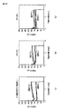
最初の実験では、媒体として100mm×148mmで厚さ0.2mmの紙(いわゆる厚紙)を用い、おもりは100g、引抜き速度は5mm/sとし、8秒間摩擦力を測定した。図10に、周囲の温度を調節した下での測定結果を示す。(a)(b)(c)はそれぞれ周囲の温度を5℃、20℃、60℃に調節した下での測定に対応し、それぞれ3回ずつ摩擦力を測定した結果を重ねて表す(なお、(a)は湿度測定不可(加湿無し)、(b)は湿度65%、(c)は湿度50%である)。この結果、温度が低いほど加振時に摩擦力が大きく低下する傾向がみられた。 In the first experiment, a paper of 100 mm × 148 mm and a thickness of 0.2 mm (so-called thick paper) was used as a medium, the weight was 100 g, the drawing speed was 5 mm / s, and the friction force was measured for 8 seconds. FIG. 10 shows the measurement results under the ambient temperature adjusted. (A), (b) and (c) correspond to the measurement under the condition that the ambient temperature is adjusted to 5 ° C., 20 ° C. and 60 ° C., respectively, and the results of measuring the frictional force three times each are shown in an overlapping manner (note that (A) cannot measure humidity (no humidification), (b) has a humidity of 65%, and (c) has a humidity of 50%). As a result, the lower the temperature, the more the frictional force tended to decrease during vibration.
次に、厚紙は湿度の影響を受けるため、湿度の影響を受けない媒体として100mm×148mmで厚さ0.2mmのSUS板を用い、同様の実験を行った。 Next, since the cardboard is affected by humidity, a similar experiment was performed using a 100 mm × 148 mm SUS plate having a thickness of 0.2 mm as a medium not affected by humidity.
図11に、湿度50%の乾燥状態で測定した各温度での摩擦力を示す。(a)(b)(c)はそれぞれ周囲の温度を5℃、20℃、60℃に調節した下での測定に対応し、それぞれ3回ずつ摩擦力を測定した結果を重ねて表す(なお、(a)は湿度測定不可(加湿無し)である)。 FIG. 11 shows the frictional force at each temperature measured in a dry state with a humidity of 50%. (A), (b) and (c) correspond to the measurement under the condition that the ambient temperature is adjusted to 5 ° C., 20 ° C. and 60 ° C., respectively, and the results of measuring the frictional force three times each are shown in an overlapping manner (note that (A) cannot measure humidity (no humidification)).
図12に、湿度80%以上の加湿状態で測定した各温度での摩擦力を示す。(a)(b)(c)はそれぞれ周囲の温度を20℃、40℃、60℃に調節した下での測定に対応し、それぞれ3回ずつ摩擦力を測定した結果を重ねて表す(なお、5℃では湿度調節ができなかったため、40℃で測定した)。 FIG. 12 shows the frictional force at each temperature measured in a humidified state with a humidity of 80% or more. (A), (b), and (c) correspond to the measurement under the condition that the ambient temperature is adjusted to 20 ° C., 40 ° C., and 60 ° C., respectively, and the results of measuring the frictional force three times each are superimposed (represented by Since the humidity could not be adjusted at 5 ° C, it was measured at 40 ° C).
図11及び図12に示した結果ともに、温度が低いほど加振時に摩擦力が大きく低下する傾向が見られた。 In both the results shown in FIGS. 11 and 12, the lower the temperature, the greater the tendency of the friction force to decrease during excitation.
以上の本願発明者による解析及び実験結果より、高周波振動により被搬送媒体の摩擦力が減少する効果が低温環境下で高まることが示された。よって、高周波加振による摩擦力減少効果を増加させるためには、媒体の周囲の温度を低下させるようコントロールすることが有効である。 From the above analysis and experimental results by the inventors of the present application, it was shown that the effect of reducing the frictional force of the transported medium due to high-frequency vibration is enhanced in a low-temperature environment. Therefore, in order to increase the effect of reducing the frictional force due to high-frequency excitation, it is effective to control the temperature around the medium to be lowered.
一方、媒体を冷却することで媒体が結露したり凍結したりする可能性があり、媒体の種類に応じて可能な限り温度を低下させる必要がある。そこで、本実施形態では、媒体周囲又は媒体の温度をモニターし、温度コントロール可能な構成をとる。 On the other hand, there is a possibility that the medium is condensed or frozen by cooling the medium, and it is necessary to reduce the temperature as much as possible according to the type of the medium. Therefore, in the present embodiment, the temperature around the medium or the temperature of the medium is monitored and the temperature can be controlled.
本実施形態の基本的な構成としては、搬送対象となる薄板状媒体に振動を加える振動部と、前記薄板状媒体に近接する空気を冷却する冷却部と、前記薄板状媒体を搬送させる搬送部と、前記薄板状媒体の周囲の温度を検出する温度検出部と、前記温度検出部により検出された温度に基づいて前記冷却部を制御する制御部とを備える。 As a basic configuration of the present embodiment, a vibration unit that applies vibration to a thin plate medium to be conveyed, a cooling unit that cools air adjacent to the thin plate medium, and a conveyance unit that conveys the thin plate medium And a temperature detection unit that detects a temperature around the thin plate medium, and a control unit that controls the cooling unit based on the temperature detected by the temperature detection unit.
本実施形態によれば、高周波振動による摩擦力低減効果を、増加させることができる(あるいは、媒体の状態に悪影響を与えない範囲で、増加させることができる)。 According to the present embodiment, the frictional force reduction effect due to the high-frequency vibration can be increased (or can be increased as long as the state of the medium is not adversely affected).
以下、幾つかの実施形態についてより詳しく説明する。 Hereinafter, some embodiments will be described in more detail.
(第1の実施形態)
第1の実施形態について説明する。
(First embodiment)
A first embodiment will be described.
本実施形態は、非連続・薄板状媒体を搬送する媒体搬送装置に関するものである。 The present embodiment relates to a medium conveying apparatus for conveying a discontinuous / thin plate-like medium.
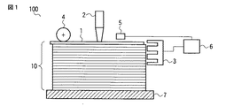
図1に、第1の実施形態に係る媒体搬送装置100の構成例を示す。
FIG. 1 shows a configuration example of a
図1に示されるように、媒体搬送装置100は、搬送対象となる、積層された薄板状媒体(以下、積層媒体)10の最上面に位置する媒体1を加振する振動体2と、媒体の周囲及び媒体間の空気を冷却する機構として空気冷却部3と、媒体を搬送させるための搬送機構として積層媒体10の最上面の媒体1に搬送力を与える搬送部4と、媒体の周囲の気温をモニターする温度検出部5と、温度検出部5による温度検出結果に応じて上記空気冷却部3の出力をコントロールする制御部6を含む。図中、7は積載台である。
As shown in FIG. 1, the
積層媒体10の一つ一つの薄板状媒体は、前述のとおり、例えば、有価証券や鋼板などの薄い紙やプラスチックや金属からなる媒体が積層されたものであっても良い。 Each thin plate-like medium of the laminated medium 10 may be a medium in which thin paper such as securities or steel plates, or a medium made of plastic or metal is laminated as described above.
媒体搬送装置100は、媒体を1枚1枚、所定のタイミングで取り出して(例えば媒体を処理する処理部(図示せず)に)送り出す機能をもつ装置である。媒体搬送装置100は、例えば郵便物処理装置などの一部を構成する装置であっても良い。
The
積層媒体10は、積載台7上に配置される。積層媒体10の最上面の媒体1が搬送されると、積載台7が上昇し、それまでの2枚目の媒体が、新たな最上面の媒体となって同じ状態が保たれるようにするのが望ましい。
The
媒体搬送装置100は、積層媒体10の最上面の媒体1を搬送するために、媒体1と、媒体1の下に位置する2枚目の媒体とを分離するが、その際にそれらの間の摩擦力が低くなるように、本実施形態では、媒体に高周波加振するとともに、媒体及び媒体周囲の気体の温度を低くする。
The
振動体2は、媒体1を高周波で加振する振動体である。具体的には、例えば、BLT型振動子、積層金属磁気歪振動子、π型フェライト振動子などを用いることができる。振動体2によって媒体1を振動させることにより、媒体1とその下の2枚目の媒体との間の空気層が振動し、媒体1と2枚目の媒体との摩擦力が低下する。
The vibrating
空気冷却部3は、媒体1及び周囲の空気及び媒体間の空気(或いは、これに加えて、振動体)を冷却する機構である。具体的には、例えば、ペルチェ素子、コンプレッサを有する熱交換器などを用いることができる。図1の構成例において、例えば、空気冷却部3を積層媒体10の周囲を取り囲むように配置することで、媒体1及び周囲の空気及び媒体間の空気を冷却することとしても良いが、配置の仕方はこれに制限されない。空気冷却部3は、制御部6によりコントロールされる。
The
搬送部4は、媒体1を取り出す機構である。具体的には、例えば、ゴムローラ、吸着式ロータ、吸着式ベルトなど一般的な取出し機構を用いることができる。
The
温度検出部5は、媒体1又は媒体1の周囲の温度を測定する機構である。具体的には、例えば、熱電対、放射型非接触温度計など一般的な温度計を用いることができる。温度検出部5により測定された温度は、制御部6に入力される。温度を検出する場所としては様々な場所が考えられ、例として、振動体2及び振動体2の固定部、媒体1と振動体2との接触部、あるいは、媒体1の近傍の空気などの温度を測定するように設置できる。
The
制御部6は、空気冷却部3の出力をコントロールする機構である。媒体1又は媒体の周囲が、所定の温度になるよう、例えば一般的な制御アルゴリズムによりコントロールする。この制御アルゴリズムに、特に制限はない。所定の温度については、例えば、最適な温度を予め求めておき、これを該所定の温度として、装置に設定しておいても良い。例として、コピー用紙では用紙表面が結露すると印字性能に影響を与えるため、用紙表面に氷や霜がつかないよう、媒体温度を5℃程度にコントロールすることが好ましい。
The
図2は、第1〜第4の実施形態に係る媒体搬送装置の動作を示すフローチャートの一例である。 FIG. 2 is an example of a flowchart showing the operation of the medium carrying device according to the first to fourth embodiments.
この例では、搬送対象となる薄板状媒体が存在する間(ステップS6)、搬送対象となる薄板状媒体に振動を加え(ステップS1)、薄板状媒体を搬送するとともに(ステップS2)、一方、薄板状媒体に近接する空気を冷却し(ステップS3)、薄板状媒体の周囲の温度を検出し(ステップS4)、検出された温度に基づいて空気冷却部を制御する(ステップS5)。 In this example, while the thin plate medium to be transported exists (step S6), the thin plate medium to be transported is vibrated (step S1), and the thin plate medium is transported (step S2). The air close to the thin plate medium is cooled (step S3), the temperature around the thin plate medium is detected (step S4), and the air cooling unit is controlled based on the detected temperature (step S5).
なお、常に薄板状媒体に振動を加えるようにしても良いし、例えば搬送の前後などの一定の期間、薄板状媒体に振動を加えるようにしても良い。 Note that vibration may always be applied to the thin plate-like medium, or vibration may be applied to the thin plate-like medium for a certain period of time, for example, before and after conveyance.
また、薄板状媒体の搬送と関連付けられた所定のタイミングで、空気冷却部の出力を変化させるようにしても良いし、薄板状媒体の搬送とは無関係に、空気冷却部の出力を変化させるようにしても良い。 The output of the air cooling unit may be changed at a predetermined timing associated with the conveyance of the thin plate medium, or the output of the air cooling unit may be changed regardless of the conveyance of the thin plate medium. Anyway.
図2のフローチャートは一例であり、他の動作も可能である。 The flowchart of FIG. 2 is an example, and other operations are possible.
本実施形態によれば、薄板状媒体を搬送する際に、高周波加振するとともに、媒体の周囲の温度を低下させるよう制御するので、搬送される薄板状媒体に働く摩擦力をより軽減することができる。 According to the present embodiment, when a thin plate medium is transported, high-frequency vibration is controlled and the temperature around the medium is controlled to be reduced, so that the frictional force acting on the transported thin plate medium can be further reduced. Can do.
(第2の実施形態)
第2の実施形態について第1の実施形態と相違する点を中心に説明する。
(Second Embodiment)
The second embodiment will be described with a focus on differences from the first embodiment.
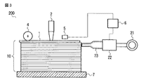
図3に、第2の実施形態に係る媒体搬送装置200の構成例を示す。
FIG. 3 shows a configuration example of a
図3に示されるように、媒体搬送装置200は、媒体の周囲及び媒体間の空気を冷却する機構として、図1(第1の実施形態)の空気冷却部3に替えて、空気を圧縮するための空気圧縮部21と、該空気圧縮部21により圧縮された空気を冷却するための空気冷却部22と、該空気冷却部22により冷却された圧縮空気を媒体(あるいは、媒体及び振動体)に向けて噴射するための噴射ノズル23とを含むものであり、それ以外は、図1の構成と同様である。
As shown in FIG. 3, the
空気圧縮部21は、空気を圧縮する機構であり、例えばコンプレッサなどにより空気を圧縮し、圧縮空気を空気冷却部22に送る機能をもつ。
The
空気冷却部22は、空気圧縮部21で圧縮された空気を冷却し、噴射ノズル23に送り出す。
The
噴射ノズル23は、媒体1に接近して配置される媒体1の近傍に冷却風を吹き込む機構である。噴射ノズル23は、媒体間の空気を冷却すると同時に、一般的な紙さばき機構として用いられているように、凝着した媒体を引きはがす効果をもつ。
The
図4に、噴射ノズルの配置例を示す。 FIG. 4 shows an arrangement example of the injection nozzles.
図中、800は被搬送媒体である積層媒体(例えば、用紙束)であり、801は通常の噴射ノズルを紙幅全体に並べたものであり、802は紙幅全体にわたる冷却風幅広導入ノズルである。 In the figure, reference numeral 800 denotes a laminated medium (for example, a sheet bundle) as a transported medium, reference numeral 801 denotes a normal jet nozzle arranged in the entire paper width, and reference numeral 802 denotes a cooling air wide introduction nozzle over the entire paper width.
媒体の周囲の空気を効率的に媒体全面で冷却するため、801に示すように噴射ノズルを紙幅全体に空気を送り込むように配置しても良いし、802に示すように紙幅全体にわたる冷却風幅広導入ノズルを利用しても良い。 In order to efficiently cool the air around the medium over the entire surface of the medium, the injection nozzle may be arranged so as to send air over the entire paper width as indicated by 801, or the cooling air width over the entire paper width as indicated by 802. An introduction nozzle may be used.
なお、積層媒体800のすべての側面について801の方法を用いても良いし、すべての側面について802の方法を用いても良いし、801の方法と802の方法とを併用しても良い。 Note that the method 801 may be used for all side surfaces of the laminated medium 800, the method 802 may be used for all side surfaces, or the method 801 and the method 802 may be used in combination.
図5に、第2の実施形態に係る媒体搬送装置230の他の構成例を示す。
FIG. 5 shows another configuration example of the
図5の媒体搬送装置230は、空気圧縮と空気冷却の順序が図3とは逆になるものであり、媒体の周囲及び媒体間の空気を冷却する機構として、空気を冷却するための空気冷却部32と、該空気冷却部32により冷却された空気を圧縮するための空気圧縮部31と、該空気圧縮部31により圧縮された冷却空気を媒体(あるいは、媒体及び振動体)に向けて噴射するための噴射ノズル33とを含むものである。それ以外は、図1及び図3の構成と同様である。
The
(第3の実施形態)
第3の実施形態についてこれまでの実施形態と相違する点を中心に説明する。
(Third embodiment)
The third embodiment will be described with a focus on differences from the previous embodiments.
図6に、第3の実施形態に係る媒体搬送装置300の構成例を示す。
FIG. 6 shows a configuration example of a
図3に示されるように、媒体搬送装置300は、図3(第2の実施形態)の構成に加え、媒体を除湿するための機構として、空気を圧縮するための空気圧縮部41と、該空気圧縮部41により圧縮された空気を除湿するための空気除湿部42と、該空気除湿部42により除湿された圧縮空気を媒体に向けて噴射するための噴射ノズル43とを含むものである。また、媒体搬送装置300は、用紙束しごき部51を更に含んでも良い。それら以外は、図1,図3,図5の構成と同様である。
As shown in FIG. 3, in addition to the configuration of FIG. 3 (second embodiment), the
媒体1が紙である場合、媒体冷却時に結露が生じることを防止するのが望ましい。そこで、積載台7に載せられた積層媒体10を予め除湿することが望ましい。
When the
空気除湿部42は、積層媒体10の冷却空気噴射ノズル23の下部に配置された噴射ノズル43に送り込む空気を除湿する機能を有する。除湿機構は、凝結再加熱を利用した公知の除湿機構を使用する。
The
搬送が進むにつれて積載台7が上昇するようにすれば、積載台7に載せられた各媒体は、下方から上方に移動するので、まず、除湿を受け、そして、冷却されるようになる。 If the loading table 7 is raised as the conveyance proceeds, each medium placed on the loading table 7 moves upward from below, so that it is first dehumidified and cooled.
用紙束しごき部51は、除湿空気及び冷却空気が用紙間に入りやすくするため、積層媒体の端部をしごく機構である。具体的には、例えば、ベルトを積層媒体端部に摩擦させることで積層媒体端部に空間を生じさせ、これによって空気を入りやすくするような公知の技術を応用することができる。
The sheet
なお、図6は、図3の構成に、媒体を除湿するための機構(又は、これに加えて用紙束しごき部)を付加したものであったが、図5の構成に、図6の媒体を除湿するための機構(又は、これに加えて用紙束しごき部)を付加する構成も可能である。また、そのような構成又は図6の構成において、図6の媒体を除湿するための機構に替えて、空気を除湿するための空気除湿部と、該空気除湿部により除湿された空気を圧縮するための空気圧縮部と、該空気圧縮部により圧縮された除湿空気を媒体に向けて噴射するための噴射ノズルとを含むようにしても良い。 6 shows a configuration in which a mechanism for dehumidifying the medium (or in addition to this, a sheet bundle squeezing unit) is added to the configuration in FIG. 3, but the medium in FIG. 6 is added to the configuration in FIG. It is also possible to add a mechanism (or a sheet bundle ironing unit) for dehumidifying the paper. Further, in such a configuration or the configuration of FIG. 6, instead of the mechanism for dehumidifying the medium of FIG. 6, the air dehumidifying unit for dehumidifying the air and the air dehumidified by the air dehumidifying unit are compressed. An air compression unit for the purpose and an injection nozzle for injecting dehumidified air compressed by the air compression unit toward the medium may be included.
(第4の実施形態)
第4の実施形態についてこれまでの実施形態と相違する点を中心に説明する。
(Fourth embodiment)
The fourth embodiment will be described with a focus on differences from the previous embodiments.
本実施形態は、連続・薄板状媒体を搬送する媒体搬送装置に関するものである。 The present embodiment relates to a medium conveying apparatus for conveying a continuous / thin plate-like medium.
図7に、第4の実施形態に係る媒体搬送装置400の構成例を示す。
FIG. 7 shows a configuration example of a
図7に示されるように、媒体搬送装置400は、搬送対象となる一連の媒体(ウェブ)401を加振する振動体402と、媒体の周囲及び媒体間の空気を冷却する機構として空気冷却部403と、媒体を搬送させるための搬送機構として、自ら媒体に搬送力を与えるのではなく、(他の機構により搬送力を与えられる)媒体401の搬送をサポートする搬送部404と、媒体の周囲の気温をモニターする温度検出部405と、温度検出部405による温度検出結果に応じて上記空気冷却部403の出力をコントロールする制御部406を含む。
As shown in FIG. 7, the
媒体401は、一連の媒体からなるウェブであり、前述のとおり、例えば、紙やフィルムであっても良い。 The medium 401 is a web composed of a series of media, and may be, for example, paper or film as described above.
振動体402は、媒体401が巻きつく表面が振動する構造であり、公知の振動体が使用できる。 The vibrating body 402 has a structure in which the surface around which the medium 401 is wound vibrates, and a known vibrating body can be used.
空気冷却部403は、媒体401の周囲を冷却する。
The
搬送部404は、媒体401に巻きつかれながら回転することによって、媒体401を搬送する機構である(この場合、媒体401の搬送方向を変化させる働きをもつ)。搬送部404の表面が振動する構成となっており、振動体402としても機能する。 The transport unit 404 is a mechanism that transports the medium 401 by rotating while being wound around the medium 401 (in this case, it has a function of changing the transport direction of the medium 401). The surface of the conveyance unit 404 is configured to vibrate, and also functions as the vibrating body 402.
温度検出部405は、媒体401の周囲及び振動体402の温度を測定し、制御部406に対し測定結果を出力する。制御部406は空気冷却部403の出力を調節し、媒体401の周囲の気温を所定の温度に制御する機能を有する。
The
なお、図7の例では、振動体402と搬送部404とが同じ構造物により実現されるものとしたが、搬送部404とは独立した振動体402が、搬送部404に振動を加えるような構成も可能である。 In the example of FIG. 7, the vibrating body 402 and the transport unit 404 are realized by the same structure, but the vibrating body 402 independent of the transport unit 404 applies vibration to the transport unit 404. Configuration is also possible.
なお、ウェブを搬送する媒体搬送装置について、図3,図5,図6のような冷却制御構成を適用することも可能である。 In addition, it is also possible to apply the cooling control configuration as shown in FIGS. 3, 5, and 6 to the medium transport device that transports the web.
以上の各実施形態は、用紙束やウェブを搬送する機構を例にとって説明したが、本実施形態は、高周波振動により摩擦力を減少させながら媒体を搬送する他の機構にも適用可能である。他の機構としては例えば、高周波振動を用いたウェハー搬送機構、高周波リニアスライダ機構などが挙げられる。その際、第4の実施形態で例示したように、振動体と搬送部が同一構造である機構もある。 Each of the above embodiments has been described by taking a mechanism for conveying a sheet bundle or web as an example, but this embodiment can also be applied to other mechanisms for conveying a medium while reducing frictional force by high-frequency vibration. Examples of other mechanisms include a wafer conveyance mechanism using high-frequency vibration and a high-frequency linear slider mechanism. At that time, as exemplified in the fourth embodiment, there is also a mechanism in which the vibrating body and the conveyance unit have the same structure.
本発明のいくつかの実施形態を説明したが、これらの実施形態は、例として提示したものであり、発明の範囲を限定することは意図していない。これら新規な実施形態は、その他の様々な形態で実施されることが可能であり、発明の要旨を逸脱しない範囲で、種々の省略、置き換え、変更を行うことができる。これら実施形態やその変形は、発明の範囲や要旨に含まれるとともに、特許請求の範囲に記載された発明とその均等の範囲に含まれる。 Although several embodiments of the present invention have been described, these embodiments are presented by way of example and are not intended to limit the scope of the invention. These novel embodiments can be implemented in various other forms, and various omissions, replacements, and changes can be made without departing from the scope of the invention. These embodiments and modifications thereof are included in the scope and gist of the invention, and are included in the invention described in the claims and the equivalents thereof.
1,101〜103…媒体、2…振動体、3,22,32…空気冷却部、4…搬送部、5…温度検出部、6…制御部、7…積載台、10,100…積層媒体、21,31,41…空気圧縮部、23,33,43…噴射ノズル、42…空気除湿部、51…用紙束しごき部、100,200,230,300…媒体搬送装置、120…台、122…おもり、124…振動子、123…開口部、132…ワイヤー、130…荷重計。 DESCRIPTION OF SYMBOLS 1,101-103 ... Medium, 2 ... Vibrating body, 3, 22, 32 ... Air cooling part, 4 ... Conveyance part, 5 ... Temperature detection part, 6 ... Control part, 7 ... Loading platform 10,100 ... Laminated medium 21, 31, 41... Air compression unit, 23, 33, 43 ... jet nozzle, 42 ... air dehumidification unit, 51 ... sheet bundle ironing unit, 100, 200, 230, 300 ... medium transport device, 120 ... stand, 122 ... weight, 124 ... vibrator, 123 ... opening, 132 ... wire, 130 ... load meter.
Claims (9)
前記薄板状媒体に近接する空気を冷却する冷却部と、
前記薄板状媒体を搬送させる搬送部と、
前記薄板状媒体の周囲の温度を検出する温度検出部と、
前記温度検出部により検出された温度に基づいて前記冷却部を制御する制御部とを備えたことを特徴とする媒体搬送装置。 A vibration unit for applying vibration to a thin plate-like medium to be conveyed;
A cooling unit for cooling air adjacent to the lamellar medium;
A transport unit for transporting the thin plate medium;
A temperature detection unit for detecting a temperature around the thin plate medium;
And a control unit that controls the cooling unit based on the temperature detected by the temperature detection unit.
前記制御部は、前記温度検出部により検出された温度に基づいて、前記空気冷却部の出力を制御することを特徴とする請求項1に記載の媒体搬送装置。 The cooling unit includes an air cooling unit for cooling air adjacent to the lamellar medium,
The medium transport apparatus according to claim 1, wherein the control unit controls an output of the air cooling unit based on a temperature detected by the temperature detection unit.
空気を圧縮するための空気圧縮部と、
前記空気圧縮部により圧縮された空気を冷却するための空気冷却部と、
前記空気冷却部により冷却された圧縮空気を前記薄板状媒体に向けて噴射するための噴射ノズルとを含み、
前記制御部は、前記温度検出部により検出された温度に基づいて、前記空気冷却部の出力を制御することを特徴とする請求項1に記載の媒体搬送装置。 The cooling part is
An air compression unit for compressing air;
An air cooling unit for cooling the air compressed by the air compression unit;
An injection nozzle for injecting the compressed air cooled by the air cooling unit toward the thin plate medium,
The medium transport apparatus according to claim 1, wherein the control unit controls an output of the air cooling unit based on a temperature detected by the temperature detection unit.
空気を冷却するための空気冷却部と、
前記空気冷却部により冷却された空気を圧縮するための空気圧縮部と、
前記空気圧縮部により圧縮された冷却空気を前記薄板状媒体に向けて噴射するための噴射ノズルとを含み、
前記制御部は、前記温度検出部により検出された温度に基づいて、前記空気冷却部の出力を制御することを特徴とする請求項1に記載の媒体搬送装置。 The cooling part is
An air cooling section for cooling the air;
An air compression unit for compressing the air cooled by the air cooling unit;
An injection nozzle for injecting the cooling air compressed by the air compression unit toward the thin plate medium,
The medium transport apparatus according to claim 1, wherein the control unit controls an output of the air cooling unit based on a temperature detected by the temperature detection unit.
振動部が、搬送対象となる薄板状媒体に振動を加え、
冷却部が、前記薄板状媒体に近接する空気を冷却し、
搬送部が、前記薄板状媒体を搬送させ、
温度検出部が、前記薄板状媒体の周囲の温度を検出し、
制御部が、前記温度検出部により検出された温度に基づいて前記冷却部を制御する制御方法。 In the control method of the medium transport device,
The vibration unit applies vibration to the thin plate medium to be transported,
A cooling unit cools air adjacent to the lamellar medium;
The transport unit transports the thin plate medium,
A temperature detector detects a temperature around the thin plate medium;
A control method in which the control unit controls the cooling unit based on the temperature detected by the temperature detection unit.
Priority Applications (2)
| Application Number | Priority Date | Filing Date | Title |
|---|---|---|---|
| JP2010215837A JP2012071902A (en) | 2010-09-27 | 2010-09-27 | Medium conveyor apparatus and control method |
| US13/040,362 US20120073937A1 (en) | 2010-09-27 | 2011-03-04 | Medium conveyor apparatus and control method |
Applications Claiming Priority (1)
| Application Number | Priority Date | Filing Date | Title |
|---|---|---|---|
| JP2010215837A JP2012071902A (en) | 2010-09-27 | 2010-09-27 | Medium conveyor apparatus and control method |
Publications (1)
| Publication Number | Publication Date |
|---|---|
| JP2012071902A true JP2012071902A (en) | 2012-04-12 |
Family
ID=45869506
Family Applications (1)
| Application Number | Title | Priority Date | Filing Date |
|---|---|---|---|
| JP2010215837A Pending JP2012071902A (en) | 2010-09-27 | 2010-09-27 | Medium conveyor apparatus and control method |
Country Status (2)
| Country | Link |
|---|---|
| US (1) | US20120073937A1 (en) |
| JP (1) | JP2012071902A (en) |
Cited By (1)
| Publication number | Priority date | Publication date | Assignee | Title |
|---|---|---|---|---|
| JP2014105112A (en) * | 2012-11-30 | 2014-06-09 | Toppan Forms Co Ltd | Sheet feeder |
Families Citing this family (3)
| Publication number | Priority date | Publication date | Assignee | Title |
|---|---|---|---|---|
| JP5940734B2 (en) * | 2013-08-23 | 2016-06-29 | 富士フイルム株式会社 | Paper stacking device |
| EP2962968B1 (en) * | 2014-07-01 | 2017-05-10 | Wincor Nixdorf International GmbH | Device for separating sheet goods |
| JP2025009390A (en) * | 2023-07-07 | 2025-01-20 | 株式会社リコー | Post-processing device and image forming system |
Citations (3)
| Publication number | Priority date | Publication date | Assignee | Title |
|---|---|---|---|---|
| JPH06100186A (en) * | 1992-09-22 | 1994-04-12 | Hitachi Electron Eng Co Ltd | Magnetic card pick mechanism |
| JP2000121221A (en) * | 1998-10-12 | 2000-04-28 | Orion Mach Co Ltd | Cold air generator |
| JP2003252473A (en) * | 2002-02-28 | 2003-09-10 | Toppan Forms Co Ltd | Sheet feeding device |
Family Cites Families (6)
| Publication number | Priority date | Publication date | Assignee | Title |
|---|---|---|---|---|
| US3865364A (en) * | 1973-10-04 | 1975-02-11 | Fmc Corp | Anti-curl sheet feeding apparatus |
| US4727252A (en) * | 1984-10-20 | 1988-02-23 | Fuji Photo Film Co., Ltd. | Radiation image erase unit for use with stimulable phosphor sheet |
| JP2007238206A (en) * | 2006-03-06 | 2007-09-20 | Toshiba Corp | Separation take-out device |
| JP4127708B2 (en) * | 2006-05-23 | 2008-07-30 | 株式会社東芝 | Separation and removal device for paper-like media |
| DE102007016541A1 (en) * | 2007-04-05 | 2008-10-16 | Böwe Systec AG | Apparatus and method for conveying goods from a stack to an exit |
| JP2009208858A (en) * | 2008-02-29 | 2009-09-17 | Toshiba Corp | Separation and taking-out apparatus |
-
2010
- 2010-09-27 JP JP2010215837A patent/JP2012071902A/en active Pending
-
2011
- 2011-03-04 US US13/040,362 patent/US20120073937A1/en not_active Abandoned
Patent Citations (3)
| Publication number | Priority date | Publication date | Assignee | Title |
|---|---|---|---|---|
| JPH06100186A (en) * | 1992-09-22 | 1994-04-12 | Hitachi Electron Eng Co Ltd | Magnetic card pick mechanism |
| JP2000121221A (en) * | 1998-10-12 | 2000-04-28 | Orion Mach Co Ltd | Cold air generator |
| JP2003252473A (en) * | 2002-02-28 | 2003-09-10 | Toppan Forms Co Ltd | Sheet feeding device |
Cited By (1)
| Publication number | Priority date | Publication date | Assignee | Title |
|---|---|---|---|---|
| JP2014105112A (en) * | 2012-11-30 | 2014-06-09 | Toppan Forms Co Ltd | Sheet feeder |
Also Published As
| Publication number | Publication date |
|---|---|
| US20120073937A1 (en) | 2012-03-29 |
Similar Documents
| Publication | Publication Date | Title |
|---|---|---|
| US8461562B2 (en) | Web carrier, web carrying method, and web carriage control program | |
| JP2012071902A (en) | Medium conveyor apparatus and control method | |
| JP2016161744A5 (en) | ||
| CN103130019A (en) | Sheet processing apparatus | |
| CN105073605A (en) | Packing body of plate | |
| CN105873843B (en) | Method and apparatus for applying film | |
| KR102930116B1 (en) | System and method for measuring tension distribution in a web in a roll-to-roll process | |
| JP2024040638A5 (en) | ||
| JP2016084188A (en) | Conveying device and printing device | |
| JP2012024658A (en) | Dust removal device for surface of thin film | |
| JP6163377B2 (en) | Foreign matter removal method from film laminate, film laminate production method and production apparatus. | |
| CN104786673A (en) | Recording apparatus and method of introducing recording medium to transport path | |
| US20170216897A1 (en) | Negative pressure sheet structure | |
| JP6383709B2 (en) | System, image forming device and method for realizing improved vacuum belt conveying system | |
| JP5109718B2 (en) | Method and apparatus for correcting meandering of belt-like body | |
| Dano et al. | Deformation behaviour of paper and board subjected to moisture diffusion | |
| Zhang et al. | Cohesion energy of thermally-bonded polyethylene terephthalate nonwovens: Experiments and theory | |
| JP2015047702A (en) | Image forming device | |
| JP2014231431A (en) | Separating and taking out device, and separating and taking out method | |
| JP5510832B2 (en) | Glass plate transport state reproduction device | |
| TW201217238A (en) | Glass packaging structure and glass packaging method | |
| JP2018016528A (en) | Glass substrate dividing device | |
| JP2005350174A (en) | Transport device | |
| JP2017186195A (en) | Apparatus for dividing glass substrate | |
| JP2012025539A (en) | Conveying device and recording device |
Legal Events
| Date | Code | Title | Description |
|---|---|---|---|
| A131 | Notification of reasons for refusal |
Free format text: JAPANESE INTERMEDIATE CODE: A131 Effective date: 20120529 |
|
| A521 | Request for written amendment filed |
Free format text: JAPANESE INTERMEDIATE CODE: A523 Effective date: 20120725 |
|
| A02 | Decision of refusal |
Free format text: JAPANESE INTERMEDIATE CODE: A02 Effective date: 20120821 |