EP1832533A1 - Aiguillage pour convoyeur - Google Patents
Aiguillage pour convoyeur Download PDFInfo
- Publication number
- EP1832533A1 EP1832533A1 EP07004623A EP07004623A EP1832533A1 EP 1832533 A1 EP1832533 A1 EP 1832533A1 EP 07004623 A EP07004623 A EP 07004623A EP 07004623 A EP07004623 A EP 07004623A EP 1832533 A1 EP1832533 A1 EP 1832533A1
- Authority
- EP
- European Patent Office
- Prior art keywords
- container
- transport
- switch according
- transport element
- conveyor switch
- Prior art date
- Legal status (The legal status is an assumption and is not a legal conclusion. Google has not performed a legal analysis and makes no representation as to the accuracy of the status listed.)
- Withdrawn
Links
Images

Classifications
-
- B—PERFORMING OPERATIONS; TRANSPORTING
- B65—CONVEYING; PACKING; STORING; HANDLING THIN OR FILAMENTARY MATERIAL
- B65G—TRANSPORT OR STORAGE DEVICES, e.g. CONVEYORS FOR LOADING OR TIPPING, SHOP CONVEYOR SYSTEMS OR PNEUMATIC TUBE CONVEYORS
- B65G47/00—Article or material-handling devices associated with conveyors; Methods employing such devices
- B65G47/74—Feeding, transfer, or discharging devices of particular kinds or types
- B65G47/84—Star-shaped wheels or devices having endless travelling belts or chains, the wheels or devices being equipped with article-engaging elements
- B65G47/846—Star-shaped wheels or wheels equipped with article-engaging elements
-
- B—PERFORMING OPERATIONS; TRANSPORTING
- B65—CONVEYING; PACKING; STORING; HANDLING THIN OR FILAMENTARY MATERIAL
- B65G—TRANSPORT OR STORAGE DEVICES, e.g. CONVEYORS FOR LOADING OR TIPPING, SHOP CONVEYOR SYSTEMS OR PNEUMATIC TUBE CONVEYORS
- B65G29/00—Rotary conveyors, e.g. rotating discs, arms, star-wheels or cones
-
- B—PERFORMING OPERATIONS; TRANSPORTING
- B65—CONVEYING; PACKING; STORING; HANDLING THIN OR FILAMENTARY MATERIAL
- B65G—TRANSPORT OR STORAGE DEVICES, e.g. CONVEYORS FOR LOADING OR TIPPING, SHOP CONVEYOR SYSTEMS OR PNEUMATIC TUBE CONVEYORS
- B65G47/00—Article or material-handling devices associated with conveyors; Methods employing such devices
- B65G47/52—Devices for transferring articles or materials between conveyors i.e. discharging or feeding devices
- B65G47/68—Devices for transferring articles or materials between conveyors i.e. discharging or feeding devices adapted to receive articles arriving in one layer from one conveyor lane and to transfer them in individual layers to more than one conveyor lane or to one broader conveyor lane, or vice versa, e.g. combining the flows of articles conveyed by more than one conveyor
- B65G47/71—Devices for transferring articles or materials between conveyors i.e. discharging or feeding devices adapted to receive articles arriving in one layer from one conveyor lane and to transfer them in individual layers to more than one conveyor lane or to one broader conveyor lane, or vice versa, e.g. combining the flows of articles conveyed by more than one conveyor the articles being discharged or distributed to several distinct separate conveyors or to a broader conveyor lane
-
- B—PERFORMING OPERATIONS; TRANSPORTING
- B65—CONVEYING; PACKING; STORING; HANDLING THIN OR FILAMENTARY MATERIAL
- B65G—TRANSPORT OR STORAGE DEVICES, e.g. CONVEYORS FOR LOADING OR TIPPING, SHOP CONVEYOR SYSTEMS OR PNEUMATIC TUBE CONVEYORS
- B65G2201/00—Indexing codes relating to handling devices, e.g. conveyors, characterised by the type of product or load being conveyed or handled
- B65G2201/02—Articles
- B65G2201/0235—Containers
- B65G2201/0244—Bottles
- B65G2201/0247—Suspended bottles
Definitions
- the innovation relates to a conveyor switch according to the preamble protection claim. 1
- conveyor switches In transport systems or systems for transporting bottles or the like containers are often conveyor switches, i. Transport or functional elements with switch function required, for example, to divide a conveyed container flow into several individual streams and / or summarize several container streams into a single container stream and / or one or more funded container streams controlled to one or more outlets forward, etc.
- Such conveyor elements with switch function the hereinafter also referred to as a feed switch, are used for example in plants of the beverage industry for transporting bottles or similar containers between different treatment machines.
- Known conveyor crossings consist essentially of internal transport sections, each of which forms a connection for feeding or discharging the containers, and of a guide element formed by a guide rail, which is always connected to one end with an internal transport section in communication and controlled with its other end, for example, by pivoting, optionally with one of the other internal transport sections can be connected.
- a transfer gate is connected to outer container guides the transport system through which the containers are supplied or removed.
- the object of the innovation is to show a conveyor switch, which is a controlled guiding or deflecting one or more container streams in a continuous Funding procedure allows.
- a feed switch according to the protection claim 1 is formed.
- the central element of the inventive conveyor switch which can also be referred to as a combination switch because of the manifold control options, is the at least one first circulating driven, the distributor and guide element forming transport element.
- the individual ports can be controlled in the respectively desired manner associated with each other, without any interruption of the internal transport path or the continuous container flow takes place.
- the containers are introduced only in the manner corresponding to the desired forwarding of the container flow in the first example, continuously circulating transport element or in the local container recordings or discharged from these recordings. As a result, a continuous operation of the feed switch is possible.
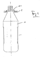
- 1 in the form of bottles of conventional design, for example, beverage bottles.
- the preferably made of plastic containers 1 each have below their container mouth a radially protruding mouth or container flange 1.1, which in particular during transport of the container 1 in a treatment plant, i. e.g. in a plant for filling, closing and labeling the container 1 for guiding and holding the respective container 1 is used.
- FIG. 1 schematically indicates a guide of a transport system to which the container 1 with its container flange 1.1 is suspended.
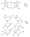
- the guide 2 is part of a transport system of a bottle or container treatment plant, which according to the figure 2, inter alia, a feed switch 3, to which in the embodiment shown in Figure 2 four guide 2 corresponding guides 2a - 2b are connected.
- the containers 1 are supplied to the conveying switch 3 via the guide 2a and / or 2b in each case as a single-lane container stream and hanging on the respective guide with the container flange 1.1.
- the containers 1 are forwarded to the guide 2c and / or 2d, in which the containers 1 are transported in turn hanging on their container flange 1.1 as a single-lane bottle stream according to the arrows C and D respectively.
- the movement of the containers 1 in the guides 2a-2d takes place e.g. by conveying or compressed air.
- the conveying direction is indicated by the arrows A - D.
- FIG. 3 Various operating states of the feed switch 3 are shown in the positions a - f in FIG. 3, wherein only those guides are shown in these positions, via which the container flow is supplied or removed.
- FIG. 4 shows a possible embodiment of the conveying switch 3 in a simplified representation and in plan view. Shown in this figure, in turn, the guides 2a - 2d.
- the guides 2a and 2b are formed in the region of the feed switch 3 by two guide elements 5 and 6 fastened to a device frame 4, on which the containers 1 are suspended with their container flange 1.1 and which are spaced from each other to form a guide slot 7.
- the guides 2a and 2b terminate in the conveying switch 3 each in an arcuate curved guide section 2a.1 and 2b.1, in which the guide slot 7 has a circular arc-shaped course and relative to the vertical axis of curvature outboard by the guide member 5 and inside by the Edge region of an around the vertical axis of curvature driven driven acceleration disc 8 is limited, so that the container 1 in the region of the guide portion 2a.1 and 2b.1 are each held with its container flange 1.1 on the guide element 5 and at the edge of the relevant acceleration disc 8 hanging ,
- the respective acceleration disc 8 is driven in the same direction with the conveying direction A or B in the direction of the arrow E, with a speed which is slightly greater than the conveying speed with which the containers 1 are fed via the guides 2a and 2b.
- the respective guide section 2a.1 or 2b.1 thus forms an acceleration section, specifically in the form that the containers 1 form a tightly packed container stream in the region of this guide section.
- Each guide section 2a or 2b ends at a transfer position 9, on which recordings 10 pass, which are provided on the circumference of a feed wheel or a feed disk 11a or 11b.
- Each feed disk 11a and 11b respectively
- Each container 1 is held with its container flange 1.1 in the respective receptacle 10 hanging.
- a guide element 12 is provided along the arc-shaped transport path formed by the respective feed disk 11 a and 11 b, on which the containers 1 are additionally supported on their container flange 1.1.
- the two guide sections 2a.1 and 2b.1 are curved in the same direction. Accordingly, the two acceleration discs 8 are driven in the same direction in the direction of the arrow E, i. in the representation chosen for the figure in a clockwise direction.
- the two feed discs 11a and 11b are each driven so that at the transfer position 9, the directions of movement of the acceleration disc 8 and the feed disc 11a and 11b are identical.
- the subsequent to the guide 2a and formed by the top in Figure 4 feed disc 11a transport path terminates at a transfer position 13.
- the subsequent to the guide 2b and formed by the bottom in the Figure 4 feed disk 11 b transport path terminates at a transfer position 14.
- An both transfer positions 13 and 14, recordings 15 and 16 move past, which are provided at equal angular intervals on the circumference of a collecting wheel or a collecting disk 17, in the form of recesses open to this extent.
- the collecting disc 17 is driven about a vertical axis in the direction of the arrow G, in synchronism with the feed discs 11a and 11b in the form that at each transfer position 13 and 14, the collecting disc 17 in the same direction and at the same speed as the feed disc in question 11a and 11b moves.
- the transfer position 13 follows the transfer position 14, namely offset by an angular amount which corresponds to three times the distance between two adjacent receptacles 15 and 16. Furthermore, the arrangement is such that each receptacle 10 of the collecting disk 11a only encounters a receptacle 16 at the transfer position 13 on only one of the receptacles 15 and each receptacle 10 of the feed disc 11b at the transfer position 14.
- each receptacle 10 of the feed disc 11a at the transfer position 13 only in each case on a receptacle 15 of the collecting disk 17 and each receptacle 10 of the feed disc 11 b at the transfer position 14 only hits a receptacle 16 of the collecting disk 17, it is ensured that each receptacle 15 at the transfer position 13 for receiving a container 1 free is, that is not already occupied at the preceding in the direction of rotation G transfer position 14 with a container 1.
- the guides 2c and 2d adjoin this transport path at transitions 2c.1 and 2d.1, respectively.
- the transitions 2c.1 and 2d.1 are in turn provided in the direction of rotation G of the collecting disc 17 by an angular amount corresponding, for example, an odd integer multiple of the distance of the receptacles 15 and 16, i. in the illustrated embodiment, the threefold distance of these shots.
- the transition 2d.1 is formed, for example, so that each container 1, which was carried along with the collecting disk 17 up to this transition, inevitably enters the guide 2d, which is formed within the conveyor 3 of the guide member 20 and the other guide member 21 .
- a deflection or removal element 22 is provided, with which in the activated state contained in the receptacles 15 or 16 container 1 are discharged controlled in the guide 2c and which in the non-activated state existing in the receptacles 15 and 16 container. 1 leaves in these recordings, so that they then pass through the transition 2d.1 to the guide 2d.
- the guide 2c is formed in the region of the conveying switch 3 by a section of the guide element 19 and by a further guide element 23.
Landscapes
- Engineering & Computer Science (AREA)
- Mechanical Engineering (AREA)
- Branching, Merging, And Special Transfer Between Conveyors (AREA)
Applications Claiming Priority (1)
| Application Number | Priority Date | Filing Date | Title |
|---|---|---|---|
| DE200620003690 DE202006003690U1 (de) | 2006-03-09 | 2006-03-09 | Förderweiche |
Publications (1)
| Publication Number | Publication Date |
|---|---|
| EP1832533A1 true EP1832533A1 (fr) | 2007-09-12 |
Family
ID=36643597
Family Applications (1)
| Application Number | Title | Priority Date | Filing Date |
|---|---|---|---|
| EP07004623A Withdrawn EP1832533A1 (fr) | 2006-03-09 | 2007-03-07 | Aiguillage pour convoyeur |
Country Status (2)
| Country | Link |
|---|---|
| EP (1) | EP1832533A1 (fr) |
| DE (1) | DE202006003690U1 (fr) |
Cited By (9)
| Publication number | Priority date | Publication date | Assignee | Title |
|---|---|---|---|---|
| US7810629B2 (en) | 2004-02-02 | 2010-10-12 | Krones Ag | Device for dynamic storage of objects |
| US7926642B2 (en) | 2004-10-16 | 2011-04-19 | Krones Ag | Device for the buffering of objects |
| DE102009051880A1 (de) * | 2009-11-04 | 2011-05-05 | Laufer, Hans-Jörg | Förderanlage für Getränkebehälter |
| US8028815B2 (en) | 2006-07-29 | 2011-10-04 | Krones Ag | Conveying device |
| US8028820B2 (en) | 2006-02-20 | 2011-10-04 | Krones Ag | Device for storing objects |
| US8162129B2 (en) | 2006-03-16 | 2012-04-24 | Krones Ag | Conveyance means |
| US8162127B2 (en) | 2005-08-27 | 2012-04-24 | Krones Ag | Dynamic storage for objects |
| DE102014103394A1 (de) * | 2014-03-13 | 2015-09-17 | Krones Ag | Vorrichtung und Verfahren zum Transportieren von Kunststoffvorformlingen |
| DE102021134109A1 (de) | 2021-12-21 | 2023-06-22 | Krones Aktiengesellschaft | Vorrichtung und Verfahren zum Verteilen von Behältern |
Families Citing this family (4)
| Publication number | Priority date | Publication date | Assignee | Title |
|---|---|---|---|---|
| DE102006039090A1 (de) * | 2006-08-19 | 2008-02-21 | Khs Ag | Antrieb für Rotationsmaschinen |
| DE102010027077A1 (de) * | 2010-07-13 | 2012-01-19 | Krones Aktiengesellschaft | Aseptische Abfüllanlage |
| DE102011055780A1 (de) | 2011-11-28 | 2013-05-29 | Krones Ag | Verfahren und system zum ordnen mehrerer in einem massenstrom bewegter artikel |
| ITBO20130262A1 (it) * | 2013-05-24 | 2014-11-25 | Gd Spa | Dispositivo alimentatore di prodotti di ridotte dimensioni longitudinali di macchine del settore del tabacco. |
Citations (5)
| Publication number | Priority date | Publication date | Assignee | Title |
|---|---|---|---|---|
| DE4203679A1 (de) * | 1992-02-08 | 1993-08-12 | Alfill Getraenketechnik | Verfahren und vorrichtung zum ueberfuehren einer gruppe von behaelterstroemen in einen einzigen behaelterstrom |
| JPH05238540A (ja) * | 1992-02-24 | 1993-09-17 | Toyo Seikan Kaisha Ltd | 円筒缶の集合供給方法及び装置 |
| US6168004B1 (en) * | 1998-11-05 | 2001-01-02 | Kalish Canada, Inc. | Container distribution apparatus |
| WO2003037760A1 (fr) * | 2001-10-30 | 2003-05-08 | Khs Maschinen- Und Anlagenbau Aktiengesellschaft | Dispositif de separation de bouteilles de boisson presentant une collerette |
| DE60008905T2 (de) * | 1999-10-29 | 2005-01-05 | Sérac Group | Fördervorrichtung für behälter mit einer ablenkeinrichtung |
-
2006
- 2006-03-09 DE DE200620003690 patent/DE202006003690U1/de not_active Expired - Lifetime
-
2007
- 2007-03-07 EP EP07004623A patent/EP1832533A1/fr not_active Withdrawn
Patent Citations (5)
| Publication number | Priority date | Publication date | Assignee | Title |
|---|---|---|---|---|
| DE4203679A1 (de) * | 1992-02-08 | 1993-08-12 | Alfill Getraenketechnik | Verfahren und vorrichtung zum ueberfuehren einer gruppe von behaelterstroemen in einen einzigen behaelterstrom |
| JPH05238540A (ja) * | 1992-02-24 | 1993-09-17 | Toyo Seikan Kaisha Ltd | 円筒缶の集合供給方法及び装置 |
| US6168004B1 (en) * | 1998-11-05 | 2001-01-02 | Kalish Canada, Inc. | Container distribution apparatus |
| DE60008905T2 (de) * | 1999-10-29 | 2005-01-05 | Sérac Group | Fördervorrichtung für behälter mit einer ablenkeinrichtung |
| WO2003037760A1 (fr) * | 2001-10-30 | 2003-05-08 | Khs Maschinen- Und Anlagenbau Aktiengesellschaft | Dispositif de separation de bouteilles de boisson presentant une collerette |
Cited By (9)
| Publication number | Priority date | Publication date | Assignee | Title |
|---|---|---|---|---|
| US7810629B2 (en) | 2004-02-02 | 2010-10-12 | Krones Ag | Device for dynamic storage of objects |
| US7926642B2 (en) | 2004-10-16 | 2011-04-19 | Krones Ag | Device for the buffering of objects |
| US8162127B2 (en) | 2005-08-27 | 2012-04-24 | Krones Ag | Dynamic storage for objects |
| US8028820B2 (en) | 2006-02-20 | 2011-10-04 | Krones Ag | Device for storing objects |
| US8162129B2 (en) | 2006-03-16 | 2012-04-24 | Krones Ag | Conveyance means |
| US8028815B2 (en) | 2006-07-29 | 2011-10-04 | Krones Ag | Conveying device |
| DE102009051880A1 (de) * | 2009-11-04 | 2011-05-05 | Laufer, Hans-Jörg | Förderanlage für Getränkebehälter |
| DE102014103394A1 (de) * | 2014-03-13 | 2015-09-17 | Krones Ag | Vorrichtung und Verfahren zum Transportieren von Kunststoffvorformlingen |
| DE102021134109A1 (de) | 2021-12-21 | 2023-06-22 | Krones Aktiengesellschaft | Vorrichtung und Verfahren zum Verteilen von Behältern |
Also Published As
| Publication number | Publication date |
|---|---|
| DE202006003690U1 (de) | 2006-06-14 |
Similar Documents
| Publication | Publication Date | Title |
|---|---|---|
| EP1832533A1 (fr) | Aiguillage pour convoyeur | |
| EP3022138B1 (fr) | Procédé et dispositif de transport pour le réagencement d'un premier flux de contenants en un second flux de contenants | |
| EP0585685B1 (fr) | Dispositif pour la transition d'un flux de récipients alignés arrivant en une seule rangée sur plusieurs rangées d'évacuation | |
| EP2001774B1 (fr) | Systeme de transport de bouteilles ou de recipients similaires et installation de traitement de bouteilles ou de recipients similaires | |
| EP2179960B1 (fr) | Dispositif de transport de récipients | |
| DE3124032C1 (de) | Behandlungsmaschine fuer Gegenstaende,insbesondere Etikettiermaschine oder Fueller fuer Behaelter,wie Flaschen | |
| EP2826718B1 (fr) | Dispositif de transport pour une machine de traitement de récipients | |
| EP1992579A1 (fr) | Dispositif de déplacement de fûts par rapport à une bande de transport | |
| DE102008046366A1 (de) | Zentriereinheit zum Ausrichten von mindestens zwei gruppierten Gefäßen sowie Verfahren zum Ausrichten von zwei gruppierten Gefäßen | |
| EP2444363B1 (fr) | Dispositif et procédé destinés à la fermeture de récipients avec bouchons | |
| DE102012206295A1 (de) | Abfüllanlage für Behälter und Verfahren zum Betreiben der Abfüllanlage | |
| EP3573910B1 (fr) | Installation de traitement de contenants et procédé de transport d'éléments fonctionnels dans une installation de traitement de contenants destinée à traiter des contenants | |
| DE102020130535A1 (de) | Abfüllanlage für flüssige Produkte und Verfahren zur Abfüllung flüssiger Produkte in Flaschen | |
| EP2733096B1 (fr) | Dispositif permettant de mettre en tampon des pièces moulées dans une installation de remplissage de boissons | |
| DE3529716A1 (de) | Vorrichtung zum ueberfuehren von aufrecht stehenden gefaessen zwischen zwei foerderern mit unterschiedlicher teilung | |
| DE60018456T2 (de) | Transportvorrichtung von einzelteilen mit einer verteilungsvorrichtung und blasformanlage zu herstellung von behältern mit einer solchen transportvorrichtung | |
| DE4442586B4 (de) | Vorrichtung zum Verteilen von Gefäßen | |
| DE4242163C2 (de) | Verfahren zum Behandeln von Gefäßen und Anlage zu dessen Durchführung | |
| DE102020116779A1 (de) | Behälterbehandlungsvorrichtung | |
| EP4232384A1 (fr) | Roue en étoile de transport pour transporter des contenants | |
| EP1544108B1 (fr) | Dispositif pour emballer des récipients dans containers | |
| EP1609747B1 (fr) | Dispositif pour la redirection de caisses transportées sur un premier convoyeur | |
| DE2808042A1 (de) | Vorrichtung zur bearbeitung, insbesondere zum fuellen und verschliessen von ampullen o.dgl. | |
| EP0873951B1 (fr) | Dispositif pour diviser un courant de récipients qui arrivent en une seule ligne | |
| WO2023078706A1 (fr) | Dispositif d'alimentation et procédé d'alimentation permettant d'alimenter et de transférer des récipients dans une machine de nettoyage de récipients |
Legal Events
| Date | Code | Title | Description |
|---|---|---|---|
| PUAI | Public reference made under article 153(3) epc to a published international application that has entered the european phase |
Free format text: ORIGINAL CODE: 0009012 |
|
| AK | Designated contracting states |
Kind code of ref document: A1 Designated state(s): AT BE BG CH CY CZ DE DK EE ES FI FR GB GR HU IE IS IT LI LT LU LV MC MT NL PL PT RO SE SI SK TR |
|
| AX | Request for extension of the european patent |
Extension state: AL BA HR MK YU |
|
| 17P | Request for examination filed |
Effective date: 20080312 |
|
| 17Q | First examination report despatched |
Effective date: 20080418 |
|
| AKX | Designation fees paid |
Designated state(s): AT BE BG CH CY CZ DE DK EE ES FI FR GB GR HU IE IS IT LI LT LU LV MC MT NL PL PT RO SE SI SK TR |
|
| RAP1 | Party data changed (applicant data changed or rights of an application transferred) |
Owner name: KHS GMBH |
|
| STAA | Information on the status of an ep patent application or granted ep patent |
Free format text: STATUS: THE APPLICATION IS DEEMED TO BE WITHDRAWN |
|
| 18D | Application deemed to be withdrawn |
Effective date: 20111005 |