EP1832428B1 - Liquid ejection apparatus having liquid transfer device - Google Patents
Liquid ejection apparatus having liquid transfer device Download PDFInfo
- Publication number
- EP1832428B1 EP1832428B1 EP05820334A EP05820334A EP1832428B1 EP 1832428 B1 EP1832428 B1 EP 1832428B1 EP 05820334 A EP05820334 A EP 05820334A EP 05820334 A EP05820334 A EP 05820334A EP 1832428 B1 EP1832428 B1 EP 1832428B1
- Authority
- EP
- European Patent Office
- Prior art keywords
- transfer device
- duct
- tank
- waste liquid
- ink
- Prior art date
- Legal status (The legal status is an assumption and is not a legal conclusion. Google has not performed a legal analysis and makes no representation as to the accuracy of the status listed.)
- Not-in-force
Links
Images


Classifications
-
- B—PERFORMING OPERATIONS; TRANSPORTING
- B41—PRINTING; LINING MACHINES; TYPEWRITERS; STAMPS
- B41J—TYPEWRITERS; SELECTIVE PRINTING MECHANISMS, i.e. MECHANISMS PRINTING OTHERWISE THAN FROM A FORME; CORRECTION OF TYPOGRAPHICAL ERRORS
- B41J2/00—Typewriters or selective printing mechanisms characterised by the printing or marking process for which they are designed
- B41J2/005—Typewriters or selective printing mechanisms characterised by the printing or marking process for which they are designed characterised by bringing liquid or particles selectively into contact with a printing material
- B41J2/01—Ink jet
- B41J2/17—Ink jet characterised by ink handling
- B41J2/18—Ink recirculation systems
- B41J2/185—Ink-collectors; Ink-catchers
-
- B—PERFORMING OPERATIONS; TRANSPORTING
- B41—PRINTING; LINING MACHINES; TYPEWRITERS; STAMPS
- B41J—TYPEWRITERS; SELECTIVE PRINTING MECHANISMS, i.e. MECHANISMS PRINTING OTHERWISE THAN FROM A FORME; CORRECTION OF TYPOGRAPHICAL ERRORS
- B41J2/00—Typewriters or selective printing mechanisms characterised by the printing or marking process for which they are designed
- B41J2/005—Typewriters or selective printing mechanisms characterised by the printing or marking process for which they are designed characterised by bringing liquid or particles selectively into contact with a printing material
- B41J2/01—Ink jet
- B41J2/135—Nozzles
- B41J2/165—Preventing or detecting of nozzle clogging, e.g. cleaning, capping or moistening for nozzles
- B41J2/16517—Cleaning of print head nozzles
- B41J2/1652—Cleaning of print head nozzles by driving a fluid through the nozzles to the outside thereof, e.g. by applying pressure to the inside or vacuum at the outside of the print head
- B41J2/16523—Waste ink collection from caps or spittoons, e.g. by suction
-
- B—PERFORMING OPERATIONS; TRANSPORTING
- B41—PRINTING; LINING MACHINES; TYPEWRITERS; STAMPS
- B41J—TYPEWRITERS; SELECTIVE PRINTING MECHANISMS, i.e. MECHANISMS PRINTING OTHERWISE THAN FROM A FORME; CORRECTION OF TYPOGRAPHICAL ERRORS
- B41J2/00—Typewriters or selective printing mechanisms characterised by the printing or marking process for which they are designed
- B41J2/005—Typewriters or selective printing mechanisms characterised by the printing or marking process for which they are designed characterised by bringing liquid or particles selectively into contact with a printing material
- B41J2/01—Ink jet
- B41J2/17—Ink jet characterised by ink handling
- B41J2/1721—Collecting waste ink; Collectors therefor
Definitions
- the present invention relates to a transfer device for connecting an ejection head and a tank storing liquid supplied to the ejection head, and to a liquid ejection apparatus including the transfer device.
- An inkjet printer is known as liquid ejection apparatus having liquid ejection mechanism for ejecting liquid in dots from nozzles of an ejection head.
- the inkjet printer may be either a printer having an on-carriage ink supply system in which an ink cartridge is mounted on a carriage or a printer having an off-carriage ink supply system in which an ink cartridge is mounted at a position separated from a carriage such as on a main body of the printer.
- a printer of the off-carriage ink supply system may use a large-capacity ink cartridge to print large-volume data or to perform printing on large-sized paper. Further, without having to mount an ink cartridge on its carriage, the printer of the off-carriage ink supply system can downsize the carriage and prevent the size of the entire printer from increasing.
- the printer of the off-carriage ink supply system requires its ink cartridge to be mounted in a limited space within the frame of the printer. This limits the capacity of the ink cartridge. Thus, to continuously print a large volume of printed matter, the ink cartridge must be frequently replaced. Such work is troublesome.
- Patent documents 1 and 2 disclose ink supply apparatuses that have been proposed to overcome such a problem.
- a tank having a plurality of ink supply cartridges on its base is arranged outside the printer.
- An ink supply duct is connected to each ink supply cartridge.
- the ink supply ducts are connected to the ink cartridges of the printer so as to automatically supply ink from the ink supply cartridges to the ink cartridges of the printer via the ink supply ducts.
- an attachment is attached to a carriage of a printer, and ink is supplied from an external ink tank to the attachment.
- an apparatus for drawing in waste ink is arranged in a region outside the print range (at a location corresponding to the home position of the recording head) at one side of the frame to prevent ink from drying and hardening in the nozzle portion of the recording head, which functions as an ejection head.
- This waste ink suction apparatus includes a suction pump and a waste liquid tank connected to the suction pump by a duct. Ink is drawn in from the nozzles of the recording head by the suction pump, and the ink is collected in the waste liquid tank as waste liquid.
- the waste liquid tank is arranged in a limited space within the frame. This limits the collection capacity of the waste liquid.
- the limited capacity of the waste ink suction apparatus that collects the waste liquid makes it difficult to perform large-volume printing.
- each ink supply duct When the printer uses the off-carriage ink supply system, the distal end of each ink supply duct must be directly connected to the corresponding ink cartridge on the printer.
- the structure of the ink cartridge is not applicable for such connection.
- the user is required to process the ink cartridge in order to connect the ink duct to the ink cartridge. Such preprocessing for the connection is extremely troublesome.
- the ink supply apparatus of patent document 1 used in a printer of the on-carriage ink supply system also requires each ink supply duct to be connected to the corresponding ink cartridge on the carriage, and the preprocessing for enabling the connection is as troublesome as in the case of the off-carriage ink supply system.
- the ink supply system of patent document 2 has the attachment mounted on the carriage instead of the ink cartridge as described above, and a tube extending from the ink tank is connected to the attachment.
- the weight held by the carriage greatly differs from the weight held when an ink cartridge is mounted on the carriage. This may adversely affect the operation of the carriage and lower the printing quality.
- the tube which extends from the ink tank that is arranged outside the printer, is connected to the cartridge on the carriage in the structure of patent document 2.
- the tube may be an obstruction when closing a cover, which is located above a carriage moving region. As a result, dust may easily enter the printer, and the aesthetic appeal of the printer may be lowered.
- the carriage reciprocates in a state in which the tube is connected to the attachment on the carriage in the structure of patent document 2.
- the tube is also moved whenever the carriage reciprocates.
- the movement of the carriage may forcibly pull or bend the tube. This may consequently generate excessive load when the carriage moves or interfere with the smooth supply of ink. In such a case, this would hinder high-quality printing.
- US 2003/0176005 discloses a connection between a sub-tank and a main tank of a liquid droplet ejecting apparatus.
- the preamble of claim 1 is based on this document.
- a first object of the present invention is to provide a waste liquid collection apparatus that enables a waste liquid tank to have a large capacity and to provide a liquid ejection apparatus including the waste liquid collection apparatus.
- a second object of the present invention is to provide a transfer device for enabling easy connection to a waste liquid tank and to provide a liquid ejection apparatus including the transfer device.
- a third object of the present invention is to provide a transfer device for ensuring simple connection of an ejection head and a tank storing liquid supplied to the ejection head without causing any of the problems described above and to provide a liquid ejection apparatus including the transfer device.
- the waste liquid collection apparatus for use in a state arranged outside a liquid ejection mechanism.
- the waste liquid collection apparatus has a waste liquid tank including a connection port connectable to a discharge side of a suction pump that draws in liquid from a nozzle of an ejection head arranged in the liquid ejection mechanism.
- the liquid ejection apparatus has a liquid ejection mechanism including an ejection head for ejecting liquid from a nozzle and a suction pump for drawing in liquid from the nozzle of the ejection head when the ejection head is not ejecting liquid, and the above waste liquid collection apparatus.
- a transfer device including a waste liquid transfer passage having an upstream end and a downstream end.
- the upstream end of the waste liquid transfer passage includes a pump side connection port connected to a discharge side of a suction pump for drawing in liquid from a nozzle of an ejection head, and the downstream end of the waste liquid transfer passage includes a discharge port for discharging the liquid drawn in by the suction pump.
- the liquid ejection apparatus includes an ejection head for ejecting liquid, and a suction pump for drawing in liquid from a nozzle of the ejection head.
- the suction pump has a discharge side connected by a duct to the pump side connection port of the above transfer device.
- the present invention provides a transfer device as recited in the claims including a transfer passage having an upstream end and a downstream end.
- the upstream end of the transfer passage includes a tank side connection port connected to a duct extending from a tank containing liquid, and the downstream end of the transfer passage includes a head side connection port connected to a duct extending from an ejection head for ejecting liquid supplied from the tank.
- the transfer device includes a storage unit for storing data on an attribute of the transfer device.
- the present invention further provides a liquid ejection apparatus.
- the liquid ejection apparatus includes an ejection head for ejecting liquid onto a target, and an apparatus frame including an attaching portion.
- the above transfer device is attached to the attaching portion, and the head side connection port of the transfer device is connected by a duct to the ejection head.
- the liquid ejection apparatus includes a reading means for reading a content of the storage unit of the transfer device.
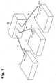
- a first printer system serving as a liquid ejection system includes inkjet printers 11 functioning as a plurality of liquid ejection apparatuses arranged in parallel.
- a single waste liquid tank 35 forming a waste liquid collection apparatus is arranged behind the printers 11.
- a plurality of second waste liquid ducts 37 extend from the waste liquid tank 35.
- Each second waste liquid duct 37 has a distal end detachably connected to a transfer device 31 for waste liquid arranged in a rear portion of the corresponding printer 11.
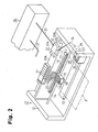
- a platen 13 is arranged on a frame 12, and a paper feeding mechanism (not shown) feeds a paper P, which functions as a print medium, onto the platen 13.
- a guide member 14 is arranged on the frame 12 to extend in parallel to the platen 13, and a carriage 15 is movably supported on the guide member 14.
- the carriage 15 is operably connected to a carriage motor 17 by a timing belt 16. The carriage 15 reciprocates within a predetermined range along the guide member 14 when the carriage motor 17 is driven.
- Six valve units 19 for supplying ink, which functions as a liquid, to the recording head 18 are mounted on the carriage 15.
- the valve units 19 temporary store six colors (six kinds) of ink used in the printer 11.
- the recording head 18 has a plurality of nozzles arranged on its lower side (not shown), and ink is ejected in dots from the nozzles onto the paper P, which functions as a target, through the valve units 19 to perform printing.
- a first attaching portion 20A and a second attaching portion 20B are defined by recesses in the rear portion of the frame 12.
- Six ink cartridges 21 are detachably attached to one side of the first attaching portion 20A.
- the ink cartridges 21 contain different colors of ink.
- a supply duct 22, which is formed by a flexible tube, is connected to each ink cartridge 21.
- Each supply duct 22 has a distal end connected to the corresponding valve unit 19 of the recording head 18.
- the air pressure generated by a pressurizing pump (not shown) supplies ink from each ink cartridge 21 to the corresponding valve unit 19 of the recording head 18 through the corresponding supply duct 22.
- an ink suction apparatus 25 for drawing in ink from the nozzles of the recording head 18 is arranged at a location corresponding to a home position of the recording head 18 at one side of the frame 12 in a region that is outside a print range.
- the ink suction apparatus 25 includes a flat and substantially square box-shape cap 26, which has an open top surface, an ink tube 27, which extends from the bottom of the cap 26, a check valve 28, which is arranged near the inlet of the ink tube 27, and a suction pump 29, which is a tube pump forming part of the liquid ejection mechanism near the outlet of the ink tube 27.
- An absorbent (sponge) 30 containing ink is arranged in the cap 26.
- the carriage 15 is moved to the home position when printing is suspended, and a drive means (not shown) raises the cap 26 to cover the nozzles of the recording head 18. This prevents the ink remaining in the nozzles from drying.
- the transfer device 31 for waste liquid is detachably attached to the second attaching portion 20B of the frame 12.
- the transfer device 31 has a rear surface exposed from the frame 12. Further, the transfer device 31 has a square block-shaped main body 32.
- a waste liquid transfer passage 33 is formed in the main body 32.
- a cylindrical pump side connection port 33a which is located at the front end of the waste liquid transfer passage 33, projects from the main body 32.
- a cylindrical discharge port 33b which is located at the rear end of the waste liquid transfer passage 33, projects from the main body 32.
- the pump side connection port 33a is connected to the suction pump 29 (more specifically, to the discharge side of the suction pump 29) by a first waste liquid duct 34, which is formed by a flexible tube.
- the waste liquid tank 35 forming a waste liquid collection apparatus is arranged behind the frame 12 outside the frame 12, and ink absorbents 36 are stacked in the waste liquid tank 35.
- the second waste liquid duct 37 which extends from the waste liquid tank 35, is formed by a flexible tube.
- the second waste liquid duct 37 has a distal end forming a connection port 37a (in other words, a connection port 37a of the waste liquid tank 35) that is detachably connected to the discharge port 33b of the transfer device 31.
- a threaded portion 38 is formed on an outer circumference of the discharge port 33b of the transfer device 31, and a nut 39 is rotatably attached to the connection port 37a, which functions as a head side connection port of the second waste liquid duct 37, with a support tube 40 arranged in between.
- the nut 39 is mated with the threaded portion 38 so that the connection port 37a of the second waste liquid duct 37 is detachably connected to the discharge port 33b of the transfer device 31.
- a valve mechanism 41 functioning as a closing means is arranged in the connection between the discharge port 33b of the transfer device 31 and the connection port 37a of the second waste liquid duct 37.
- the valve mechanism 41 includes a valve seat 42 arranged in the support tube 40, a valve member 43 arranged to face the valve seat 42 so that the valve member 43 can be in contact with or spaced from the valve seat 42, a spring 44 for urging the valve member 43 toward the valve seat 42, and an open/close dog 45 having through holes 45a and formed on the discharge port 33b of the transfer device 31 to move the valve member 43.
- connection port 37a of the second waste liquid duct 37 opens.
- the urging force of the spring 44 causes the valve member 43 to contact the valve seat 42 and closes the valve mechanism 41. That is, the connection port 37a of the second waste liquid duct 37 closes.
- connection port 37a at the distal end of the second waste liquid duct 37 expending from the waste liquid tank 35, which is arranged behind the frame 12, is connected to the discharge port 33b of the transfer device 31.
- the carriage 15 moves along the guide member 14, and the ink stored in each ink cartridge 21 is supplied to the corresponding valve unit 19 by the corresponding supply duct 22 so that ink is ejected from the nozzles of the recording head 18 onto the paper P to perform printing.
- the carriage 15 moves to the home position that corresponds to the cap 26 of the ink suction apparatus 25. Then, the cap 26 covers the nozzles of the recording head 18 as shown in Fig. 3 to prevent the nozzles from drying.
- the waste liquid tank 35 is arranged outside the frame 12 of the printer 11.
- the capacity of the waste liquid tank 35 is not limited by the accommodation space in the frame 12. Accordingly, when the waste liquid tank 35 having a large capacity is used, the waste liquid drawn in from the nozzles of the recording head 18 by the suction pump 29 can be continuously collected in the waste liquid tank 35.
- the waste liquid tank 35 When the waste liquid tank 35 becomes full with waste liquid, the waste liquid tank 35 must be replaced. In such a case, the nut 39 on the distal end of the second waste liquid duct 37 extending from the waste liquid tank 35, which has become full, is removed from the threaded portion 38 of the discharge port 33b of the transfer device 31. Then, the connection port 37a on the distal end of the second waste liquid duct 37 is disconnected from the discharge port 33b. Afterwards, the waste liquid tank 35 that is full is replaced with another empty waste liquid tank, and a nut on a distal end of a second waste liquid duct extending from the empty waste liquid tank is mated with the threaded portion 38 of the discharge port 33b of the transfer device 31. Then, a connection port 37a of the second waste liquid duct is connected to the discharge port 33b.
- the second waste liquid duct 37 extending from the waste liquid tank 35 via the transfer device 31 is connected to and disconnected from the first waste liquid duct 34 extending from the discharge side of the suction pump 29.
- the waste liquid ducts 34 and 37 are connected or disconnected in a simple and ensured manner. This facilitates replacement of the waste liquid tank 35.
- the second waste liquid duct 37 is formed by a flexible tube. Thus, the second waste liquid duct 37 is easily connected to or disconnected from the discharge port 33b of the transfer device 31 and the replacement of the waste liquid tank 35 is facilitated wherever the waste liquid tank 35 is located behind the frame 12.
- valve mechanism 41 is arranged in the connection between the connection port 37a of the second waste liquid duct 37 and the discharge port 33b of the transfer device 31, and the valve mechanism 41 closes when the connection is disconnected.
- the waste liquid is prevented from leaking when the waste liquid tank 35 is replaced.
- the first printer system has the advantages described below.
- the large-capacity waste liquid tank 35 is arranged at outside the plurality of printers 11, and the waste liquid tank 35 is connected to the suction pump 29 of each printer 11. As a result, the ink drawn in from the nozzles of the recording head 18 is continuously collected in the waste liquid tank 35 so that large-volume printing can be continuously performed. Further, only one waste liquid tank 35 is arranged for the plurality of printers 11, the entire system may be miniaturized and the structure may be simplified. Further, each printer 11 does not need to include the waste liquid tank 35. This enables the size of each printer 11 to be reduced.
- connection port 37a of the second waste liquid duct 37 of the waste liquid tank 35 is connected to or disconnected from the discharge port 33b of the transfer device 31, that is, the discharge side of the suction pump 29, so that the waste liquid tank 35 can be easily connected to or disconnected from the discharge side of the suction pump 29.
- the waste liquid tank 35 can be replaced easily.
- connection port 37a of the waste liquid tank 35 is arranged at the distal end of the second waste liquid duct 37, which is formed by a flexible tube (in other words, the second waste liquid duct 37 is formed by a flexible tube).
- the flexible tube can be bent, and the waste liquid tank 35 can be arranged at any position outside the printer 11 and the connection port 37a of the second waste liquid duct 37 and be easily connected to the discharge port 33b of the transfer device 31.
- the valve mechanism 41 for opening the connection port 37a when the second waste liquid duct 37 is connected to the transfer device 31 and closing the connection port 37a when the second waste liquid duct 37 is disconnected from the transfer device 31 is arranged in the connection port 37a of the second waste liquid duct 37.
- a second printer system will now be described focusing on differences from the first printer system.
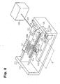
- a second printer system does not include the ink cartridges 21 of the first printer system as shown in Figs. 5 to 7 .
- an attaching portion 20 is arranged at a rear portion of a frame 12 in lieu of the first attaching portion 20A and the second attaching portion 20B in the first embodiment.
- a transfer device 51 used commonly for the supplied liquid and the waste liquid is detachably attached to the attaching portion 20 in lieu of the transfer device 31 for waste liquid in the first embodiment.
- a rear surface of the transfer device 51 is exposed from the frame 12.
- a single waste liquid transfer passage 33 that is the same as that in the first embodiment and a plurality of supply liquid transfer passages 53 are formed in parallel at predetermined intervals within a main body 52 of the transfer device 51.
- a cylindrical pump side connection port 33a is formed at a front end of the waste liquid transfer passage 33 and projects from the main body 52.
- a cylindrical discharge port 33b is formed at a rear end of the waste liquid transfer passage 33 and projects from the main body 52.
- the pump side connection port 33a is connected to a suction pump 29 by a first waste liquid duct 34, which is formed by a flexible tube.
- a head side connection port 53a which is cylindrical, is formed at a front end of each supply liquid transfer passage 53 and project from the main body 52.
- a cylindrical tank side connection port 53b is formed at a rear end of each supply liquid transfer passage 53 and projects from the main body 52.
- a upstream end of a first supply duct 54 which is formed by a flexible tube, is connected and fixed to the head side connection port 53a of each supply liquid transfer passage 53, and a downstream end of each first supply duct 54 is connected to a corresponding valve unit 19 of a recording head 18.
- a tank holder 55 which is formed by a case, is arranged behind the frame 12.
- the tank holder 55 accommodates a waste liquid tank 35 that is the same as that in the first embodiment and six large-capacity supply liquid tanks 56 containing different colors of ink in a manner that each tank is removable independently. More specifically, the tanks 35 and 56 are integrated together in a state accommodated in the tank holder 55.
- a downstream end of a second waste liquid duct 37 which is formed by a flexible tube, is connected and fixed to the waste liquid tank 35, and an upstream end of each second waste liquid duct 37 is detachably connected to the discharge port 33b of the waste liquid transfer passage 33 of the corresponding transfer device 51.
- a second supply duct 57 which is formed by a flexible tube, is connected and fixed to each supply liquid tank 56, and a downstream end of each second supply duct 57 is detachably connected to the tank side connection port 53b of the corresponding supply liquid transfer passage 53 of the transfer device 51.
- a threaded portion 38 formed on an outer circumference of the discharge port 33b is mated with a nut 39 rotatably attached to a distal end of the second waste liquid duct 37 with a support tube 40 arranged in between.
- a threaded portion 58 formed on an outer circumference of the tank side connection port 53b is mated with a nut 59 rotatably attached to a distal end of each second supply duct 57 with a support tube 60 arranged in between.
- the second waste liquid duct 37 is detachably connected to the discharge port 33b
- each second supply duct 57 is detachably connected to the corresponding tank side connection port 53b.
- a valve mechanism 61 functioning as a closing means is arranged in a connection between each second supply duct 57 and the corresponding tank side connection port 53b.
- the valve mechanism 61 includes a valve seat 62 arranged in the support tube 60 of the second supply duct 57, a valve member 63, a spring 64, and an open/close dog 65 having through-holes 65a formed on the tank side connection port 53b in the same manner as the valve mechanism 41 of the first embodiment.
- the second supply duct 57 opens.
- the urging force of the spring 64 causes the valve member 63 to contact the valve seat 62. This closes the valve mechanism 61. More specifically, the second supply duct 57 closes.
- a valve mechanism 41 that is the same as that in the first embodiment is arranged in the connection between the second waste liquid duct 37 and the discharge port 33b.
- a filter 66 is arranged in each tank side connection port 53b so that the filter 66 is located in the corresponding supply liquid transfer passage 53.
- the air pressure from a pressurizing pump (not shown) supplies ink from each supply liquid tank 56 to the corresponding valve unit 19 of the recording head 18 through the corresponding second supply duct 57, the transfer device 51, and the corresponding first supply duct 54.
- the filter 66 removes impurities and the like from the ink in the supply liquid transfer passage 53 of the transfer device 51.
- the supply liquid tanks 56 are arranged outside the frame 12 of the printer 11.
- the capacity of the supply liquid tanks 56 is not limited by the accommodation space in the frame 12.
- ink can be supplied continuously to the recording head 18 without requiring the supply liquid tanks 56 to be replaced frequently, and large-volume printing can be continuously performed.
- each first supply duct 54 is formed by a flexible tube.
- the first supply duct 54 easily bends as it follows the movement of the recording head 18 when printing is performed.
- the first supply duct 54 does not obstruct movement of the recording head 18 or the supply of ink.
- the waste liquid tank 35 and the supply liquid tanks 56 are accommodated and supported in the tank holder 55 in a removable manner, and the waste liquid tank 35 and the supply liquid tanks 56 are integrated together in a state accommodated in the tank holder 55.
- the waste liquid tank 35 and the supply liquid tanks 56 may be arranged in a manner concentrated at one position. This facilitates the attachment, removal, and replacement of the tanks 35 and 56.
- the supply liquid tank 56 When all of the ink in a supply liquid tank 56 is consumed, the supply liquid tank 56 must be replaced. In that case, the nut 59 on the distal end of the second supply duct 57 extending from the supply liquid tank 56 is removed from the threaded portion 58 of the tank side connection port 53b of the transfer device 51, and the second supply duct 57 is disconnected from the transfer device 51. Afterwards, a nut on a distal end of a second supply duct extending from another supply liquid tank that is filled with ink is mated with the threaded portion 58 of the tank side connection port 53b of the transfer device 51. In this manner, the second supply duct 57 and the tank side connection port 53b of the transfer device 51 are easily connected and disconnected.
- each second supply duct 57 is formed by a flexible tube.
- the second supply duct 57 can be easily connected to and disconnected from the tank side connection port 53b wherever the supply liquid tanks 56 are arranged behind the frame 12. This facilitates the replacement of the supply liquid tanks 56.
- the valve mechanism 61 is arranged in the connection between the distal end of the second supply duct 57 and the tank side connection port 53b of the transfer device 51, and the valve mechanism 61 closes when the connection is disconnected.
- the ink is prevented from leaking when the supply liquid tank 56 is replaced.
- the second printer system has the advantages described below in addition to the advantages of the first printer system.
- the second printer system includes the supply liquid tanks 56, each of which contains a large amount of ink that is supplied to the recording head 18.
- the printer can continuously supply ink from the supply liquid tanks 56 to the recording head 18 and continuously perform large-volume printing.
- Each second supply duct 57 between the supply liquid tank 56 and the transfer device 51 is formed by a flexible tube.
- the flexible tube can be bent, and the supply liquid tanks 56 can be arranged at any position. Further, the supply liquid tanks 56 can be easily connected to the transfer device 51.
- the valve mechanism 61 which opens when connected to the transfer device 51 and closes when disconnected from the transfer device 51, is arranged in the upstream end of the second supply duct 57. Thus, ink is prevented from leaking when the supply liquid tank 56 is replaced.
- the waste liquid tank 35 and the supply liquid tanks 56 are.detachably supported on the single tank holder 55. Thus, the entire tank may be miniaturized, and replacement of the waste liquid tank 35 and the supply liquid tanks 56 is facilitated.
- the first and second printer systems may be modified as described below.
- valve units 19 are arranged on the recording head 18 and six ink cartridges 21 are mounted on the frame 12 in the first printer system
- any number of valve units 19 and any number of ink cartridges 21 may be used.
- a printer for single color printing may include a single valve unit 19 and a single ink cartridge 21, and a printer that performs printing with the four colors of black, cyan, magenta, and yellow may include four valve units 19 and four ink cartridges 21.
- valve units 19 are arranged on the recording head 18 and six supply liquid tanks 56 are mounted on the tank holder 55 in the second embodiment, any number of valve units 19 and any number of supply liquid tanks 56 may be used.
- a printer for single color printing may include a single valve unit 19 and a single supply liquid tank 56, and a printer that performs printing with the four colors of black, cyan, magenta, and yellow may include four valve units 19 and four supply liquid tanks 56.
- the transfer device 31 may be detachably attached to the attaching portions 20A and 20B at the rear portion of the frame 12.
- the pump side connection port 33a projecting from the front surface of the transfer device 31 must be detachable from the first waste liquid duct 34.
- the transfer device 51 may be detachably attached to the attaching portion 20 at the rear portion of the frame 12.
- the head side connection port 53a projecting from the front surface of the transfer device 51 must be detachable from the first supply duct 54.
- a transfer device for ink and a transfer device for a waste liquid may be attached to the attaching portion 20 at the rear portion of the frame 12 instead of the transfer device 51 commonly used for ink and waste liquid.
- the supply liquid tanks 56 and the waste liquid tank 35 are accommodated and supported in the single tank holder 55 in a removable manner.
- the tanks 56 and 35 may be arranged at separate positions at the rear side of the frame 12 of the printer 11.
- the printer system is formed by the printers 11 that are independent from one another, and each printer 11 is connected to the single waste liquid tank 35 by a duct 37.
- the printer system may be formed by a plurality of printer mechanisms, each having a recording head and arranged on the same frame. Each printer mechanism may be connected to a single waste liquid tank 35 arranged behind the frame.
- only one printer 11 may be connected to the waste liquid tank 35.
- the pressurizing pump for supplying ink from the supply liquid tanks 56 is used.
- ink may be supplied using height difference instead of using the pressurizing pump.
- Portions of the supply duct 22, the first waste liquid duct 34, the second waste liquid duct 37, the first supply duct 54, and the second supply duct 57 may be formed by flexible tubes, and the remaining portions may be formed from a rigid body made of metal such as stainless steel or hard synthetic resin.
- a cap may be arranged to close the open end of the supply duct 22, the first waste liquid duct 34, the second waste liquid duct 37, the first supply duct 54, the second supply duct 57, the waste liquid transfer passage 33, or the supply liquid transfer passage 53 when the opening is exposed.
- the cap functions as a closing means.
- the inkjet printers 11 of the first and second printer systems may be replaced by liquid ejection apparatuses for ejecting liquids other than ink.
- the inkjet printer 11 may be a liquid ejection apparatus for ejecting liquid such as an electrode material or a color material used to manufacture, for example, a liquid crystal display, an EL (electroluminescence) display, or an FED (field emission display); a liquid ejection apparatus for ejecting living organisms for use in manufacturing a biochip; or a sample ejection apparatus such as a precision pipette.
- a platen 113 is arranged on a frame 112, and a paper feeding mechanism (not shown) feeds a paper P, which functions as a print medium, onto the platen 113.
- a guide member 114 is arranged on the frame 112 so as to extend parallel to the platen 113, and a carriage 115 is movably supported on the guide member 114.
- the carriage 115 is operably connected to a carriage motor 117 by a timing belt 116. The carriage 115 reciprocates within a predetermined range along the guide member 114 when the carriage motor 117 is driven.
- a recording head 118 functioning as an ejection head is mounted on a surface of the carriage 115 facing the platen 113.
- Six valve units 119 for supplying ink as liquid to the recording head 118 are mounted on the carriage 115.
- the valve units 119 temporary contain six colors of ink (six kinds) used in the printer 111.
- the recording head 118 has a plurality of nozzles on its lower side (not shown), and ink is ejected in dots from the nozzles onto the paper P, which functions as a target, to perform printing.
- a first attaching portion 120A and a second attaching portion 120B are defined by recesses formed in a rear portion of the frame 112.
- Six ink cartridges 121 are detachably attached to one side of the first attaching portion 120A, and the ink cartridges 121 contain ink of six different colors.
- a supply duct 122 which is formed by a flexible tube, is connected to each ink cartridge 121.
- Each supply duct 122 has a distal end connected to the corresponding valve unit 119 of the recording head 118.
- the air pressure from a pressurizing pump causes ink to be supplied from each ink cartridge 121 to the corresponding valve unit 119 of the recording head 118 through the corresponding supply duct 122.
- an ink suction apparatus 125 for drawing in ink from the nozzles of the recording head 118 is arranged at one side of the frame 112 at a location corresponding to a home position of the recording head 118 in a region outside a print range.
- the ink suction apparatus 125 includes a flat and substantially square box-shape cap 126 having a top opening, an ink tube 127 extending from the bottom of the cap 126, a check valve 128 arranged near the inlet of the ink tube 127, and a suction pump 129 formed by a squeeze-type tube pump arranged near the outlet of the ink tube 127.
- An absorbent (sponge) 130 containing ink is arranged in the cap 126.
- a transfer device 131 for waste liquid is irremovably attached to the second attaching portion 120B of the frame 112 in a manner that the transfer device 131 has a rear surface exposed from the frame 112.
- the transfer device 131 has a square block-shaped main body 132.
- a waste liquid transfer passage 133 is formed in the main body 132.
- a cylindrical pump side connection port 133a formed at the front end (upstream end) of the waste liquid transfer passage 133 projects from the main body 132.
- a cylindrical discharge port 133b formed at the rear end (downstream end) of the waste liquid transfer passage 133 projects from the main body 132.
- the pump side connection port 133a is connected to the suction pump 129 (more specifically, to a discharge side of the suction pump 129) by a first waste liquid duct 134, which is formed by a flexible tube.
- a waste liquid tank 135 is arranged behind the frame 112, and ink absorbents 136 are stacked in the waste liquid tank 135.
- a second waste liquid duct 137 extending from the waste liquid tank 135 is formed by a flexible tube.
- the second waste liquid duct 137 has a distal end detachably connected to the discharge port 133b of the transfer device 131.
- a threaded portion 138 is formed on an outer circumference of the discharge port 133b of the transfer device 131, and a nut 139 is rotatably attached to the distal end of the second waste liquid duct 137 with a support tube 140 arranged in between.
- the nut 139 is mated with the threaded portion 138 so that the second waste liquid duct 137 is detachably connected to the discharge port 133b.
- a valve mechanism 141 is arranged in a connection between the discharge port 133b of the transfer device 131 and the second waste liquid duct 137.
- the valve mechanism 141 includes a valve seat 142 arranged in the support tube 140, a valve member 143 arranged to face the valve seat 142 in a manner that the valve member 143 can be in contact with or spaced from the valve seat 142, a spring 144 for urging the valve member 143 toward the valve seat 142, and an open/close dog 145 having through-holes 145a and formed in the discharge port 133b to move the valve member 143.
- the valve member 143 When the second waste liquid duct 137 is connected to the discharge port 133b, the valve member 143 is pressed by the open/close dog 145 and spaced from the valve seat 142. As a result, the valve mechanism 141 opens. That is, the second waste liquid duct 137 opens. When the second waste liquid duct 137 is disconnected from the discharge port 133b, the urging force of the spring 144 causes the valve member 143 to contact and close the valve seat 142. That is, the second waste liquid duct 137 closes.
- the ink and the like drawn in by the suction pump 129 are discharged as waste liquid to the waste liquid tank 135 through the first waste liquid duct 134, the waste liquid transfer passage 133, and the second waste liquid duct 137 and collected in the waste liquid tank 135 in a state absorbed in the absorbents 136.
- the carriage 115 moves along the guide member 114, and the ink stored in each ink cartridge 121 is supplied to the corresponding valve unit 119 through the corresponding ink supply duct 122 so that ink is ejected in dots from the nozzles of the recording head 118 onto the paper P to perform printing.
- the carriage 115 moves to the home position corresponding to the cap 126 of the ink suction apparatus 125. Then, the cap 126 is raised to cover the nozzles of the recording head 118 as shown in the state of Fig. 9 .
- the absorbent 130 in the cap 126 prevents the nozzles from drying.
- the carriage 115 moves to the home position and the cap 126 covers the nozzles of the recording head 118 in the same manner as when the printing operation is suspended.
- the suction pump 129 is driven in this state, highly viscous ink, dust, and the like collected in the vicinity of the nozzles are drawn in.
- the drawn in ink and the like are discharged to the waste liquid tank 135 through the first waste liquid duct 134, the waste liquid transfer passage 133, and the second waste liquid duct 137, and collected in the waste liquid tank 135 in a state absorbed in the absorbents 136.
- the waste liquid tank 135 is arranged outside the frame 112 so that the capacity of the waste liquid tank 135 is not limited by the accommodation space in the frame 112.
- the waste liquid drawn in from the nozzles of the recording head 118 by the suction pump 129 can be collected continuously in the waste liquid tank 135 without the waste liquid tank 135 becoming full within a short period of time.
- the waste liquid tank 135 When the waste liquid tank 135 becomes full with waste liquid, the waste liquid tank 135 must be replaced. In such a case, the nut 139 on the distal end of the second waste liquid duct 137 extending from the waste liquid tank 135, which is full, is removed from the threaded portion 138 of the discharge port 133b of the transfer device 131. The second waste liquid duct 137 is disconnected from the discharge port 133b. Then, the full waste liquid tank 135 is replaced with an empty waste liquid tank, and a nut on a distal end of a second waste liquid duct extending from the empty waste liquid tank is mated with the threaded portion 138 of the discharge port 133b of the transfer device 131 to connect the second waste liquid duct 137 to the discharge port 133b.
- the second waste liquid duct 137 extending from the waste liquid tank 135 via the transfer device 131 is connected to and disconnected from the first waste liquid duct 134 extending from the discharge side of the suction pump 129.
- the second waste liquid duct 137 is formed by a flexible tube and the waste liquid tank 135 can thus be arranged at any position behind the frame 112.
- the second waste liquid duct 137 can be easily connected to and disconnected from the discharge port 133b of the transfer device 131 when the waste liquid tank 135 is arranged at any position behind the frame 112. This facilitates the replacement of the waste liquid tank 135.
- valve mechanism 141 which is arranged in the connection between the second waste liquid duct 137 and the discharge port 133b of the transfer device 131, closes when the connection is disconnected. Thus, the waste liquid is prevented from leaking when the waste liquid tank 135 is replaced.
- the third printer has the advantages described below.
- the waste liquid tank 135 connected to the discharge port 133b of the transfer device 131 through the second waste liquid duct 137 is arranged outside the frame 112 of the printer 111.
- the capacity of the waste liquid tank 135 is not limited by the accommodation space in the frame 112.
- the printer 111 can perform large-volume printing.
- the waste liquid tank 135 When the waste liquid tank 135 becomes full with waste liquid, the waste liquid tank 135 can be replaced easily by removing the second waste liquid duct 137 from the pump side connection port 133a of the transfer device 131. Thus, the printer 111 can continuously perform large-volume printing.
- the valve mechanism 141 for opening the distal end (upstream end) of the second waste liquid duct 137 when the second waste liquid duct 137 is connected to the transfer device 131 and closing the distal end of the second waste liquid duct 137 when the second waste liquid duct 137 is disconnected from the transfer device 131 is arranged in the discharge port 133b.
- the transfer device 131 is arranged in the inkjet printer 111 so that a large amount of waste ink may be collected in the waste liquid tank 135 from the nozzles of the recording head 118.
- the printer 111 can perform large-volume printing.
- the waste liquid tank 135 is arranged outside the frame 112 of the printer 111. Thus, the waste liquid tank 135 does not increase the size of the printer 111.
- the attaching portions 120A and 120B for attaching the transfer device 131 on the frame 112 are defined by recesses, and the attaching portions 120A and 120B are located in the rear portion of the frame 112. Thus, the transfer device 131 is not exposed to the front of the printer 111. This keeps the appearance of the printer 111 in a satisfactory state.
- a fourth printer will be described focusing on differences from the third printer.
- a transfer device 151 for supply liquid is irremovably attached to a first attaching portion 120A formed in a rear portion of a frame 112 in lieu of the ink cartridges 121 of the first embodiment.
- the transfer device 151 has a rear surface exposed from the frame 112.
- the transfer device 151 has a rectangular block-shape main body 152 and a plurality of supply liquid transfer passages 153 formed in parallel at predetermined intervals in the main body 152.
- a cylindrical head side connection port 153a formed at the front end (downstream end) of each supply liquid transfer passage 153 project from the main body 152.
- a first supply duct 154 which is formed by a flexible tube, is connected and fixed to the head side connection port 153a of each supply liquid transfer passage 153.
- Each first supply duct 154 has a distal end (downstream end) connected to a corresponding valve unit 119 of a recording head 118.
- a tank holder 155 is arranged behind the frame 112.
- the tank holder 155 detachably accommodates six large-capacity supply liquid tanks 156 containing different colors of ink.
- An upstream end of a second supply duct 157 which is formed by a flexible tube, is connected and fixed to each supply liquid tank 156, and a downstream end of each second supply duct 157 is detachably connected to the tank side connection port 153b of the corresponding supply liquid transfer passage 153 of the transfer device 151.
- a threaded portion 158 which is formed on an outer circumference of the tank side connection port 153b, and a nut 159, which is rotatably attached to a distal end of the second supply duct 157 with a support tube 160 arranged in between, are mated with each other screwed. This detachably connects each second supply duct 157 to the corresponding tank side connection port 153b.
- a valve mechanism 161 is arranged in a connection between each second supply duct 157 and the corresponding tank side connection port 153b.
- the valve mechanism 161 includes a valve seat 162 arranged in the support tube 160 of the second supply duct 157, a valve member 163, a spring 164, and an open/close dog 165 having a through-hole 165a and formed in the tank side connection port 153b in the same manner as the valve mechanism 141 of the third embodiment.
- a filter 166 is arranged in the tank side connection port 153b of each supply liquid transfer passage 153.
- the air pressure from a pressurizing pump (not shown) supplies ink from each supply liquid tank 156 to the corresponding valve unit 119 of the recording head 118 via the corresponding second supply duct 157, the transfer device 151, and the corresponding first supply duct 154.
- the filter 166 removes impurities or the like from the ink in the supply liquid transfer passage 153 of the transfer device 151.
- the transfer device 131 for waste liquid and its related structure are the same as in the third printer.
- the supply liquid tanks 156 are arranged outside the frame 112 so that the capacity of the supply liquid tanks 156 is not limited by the accommodation space in the frame 112. Thus, when the supply liquid tanks 156 having a large capacity are used, ink may be continuously supplied to the recording head 118 without requiring frequent replacement of the supply liquid tanks 156.
- the waste liquid tank 135 is arranged outside the frame 112 by way of the transfer device 131. This structure enables large-volume printing to be performed continuously.
- each first supply duct 154 is formed by a flexible tube. Thus, each first supply duct 154 easily bends as the recording head 118 moves during the printing operation. Accordingly, the first supply duct 154 does not obstruct the movement of the recording head 118 or the supply of ink.
- the supply liquid tank 156 When all of the ink in the supply liquid tank 156 is consumed, the supply liquid tank 156 must be replaced. In such a case, the nut 159 on the distal end of the second supply duct 157 extending from the supply liquid tank 156 is removed from the threaded portion 158 of the tank side connection port 153b of the transfer device 151. Then, the second supply duct 157 is disconnected from the transfer device 151. Afterwards, a nut arranged on a distal end of a second supply duct extending from another supply liquid tank, which is filled with ink, is mated with the threaded portion 158 of the tank side connection port 153b of the transfer device 151.
- each second supply duct 157 is formed by a flexible tube.
- the supply liquid tanks 156 can be arranged at any position behind the frame 112
- the second supply ducts 157 can be easily connected to and disconnected from the tank side connection ports 153b, and the replacement of the supply liquid tanks 156 can be easily performed when the supply liquid tanks 156 are arranged at any position behind the frame 112.
- valve mechanism 161 is arranged in the connection between the distal end of the second supply duct 157 and the tank side connection port 153b of the transfer device 151, and the valve mechanism 161 is closed when the connection is disconnected.
- ink is prevented from leaking when the supply liquid tank 156 is replaced.
- the fourth printer has the advantages described below in addition to the advantages of the third printer.
- the waste liquid transfer device 131 transfers waste liquid to the waste liquid tank 135 from the suction pump 129, and the supply liquid transfer device 151 transfers ink from the supply liquid tanks 156 to the recording head 118. In this case, large-volume printing can be performed with a small number of components.
- the second supply duct 157 extending from each supply liquid tank 156 is detachably connected to the corresponding tank side connection port 153b of the transfer device 151.
- This structure is preferable for continuously performing large-volume printing.
- the valve mechanism 161 which opens the distal end of the second supply duct 157 when the second supply duct 157 is connected to the transfer device 131 and closes the distal end of the second supply duct 157 when the second supply duct 157 is disconnected from the transfer device 131, is arranged on the distal end (downstream end) of the second supply duct 157. Thus, ink is prevented from leaking when the supply liquid tank 156 is replaced.
- the filter 166 arranged in each supply liquid transfer passage 153 of the transfer device 151 removes impurities and the like from the ink supplied to the recording head 118. This prevents such impurities and the like contained in the ink from causing abnormal functioning of the recording head 118 or causing ink ejection failures.
- Each first supply duct 154 between the transfer device 151 and the recording head 118 is formed by a flexible tube, and is easily bent when the recording head 118 moves. Thus, the first supply duct 154 does not obstruct movement of the recording head 118.
- Each second supply duct 157 between the transfer device 151 and the supply liquid tank 156 is formed by a flexible tube.
- the second supply duct 157 is easily connected to and disconnected from the transfer device 151, and the freedom of the arrangement of the supply liquid tank 156 is high.
- the first attaching portion 120A of the transfer device 151 is arranged in the rear portion of the frame 112. Thus, the transfer device 151 is not exposed from the front of the printer 111. This keeps the appearance of the printer 111 in a satisfactory state.
- a fifth printer will now be described focusing on differences from the third and fourth printers.
- an attaching portion 120 is arranged in a rear portion of a frame 112 in lieu of the first attaching portion 120A and the second attaching portion 120B of the third and fourth embodiments.
- a transfer device 171 is irremovably attached to the attaching portion 120.
- the transfer device 171 has a main body (case) 172 including a waste liquid transfer passage 133 that is the same as in the third and fourth printers and a plurality of supply liquid transfer passages 153, which are arranged in parallel. More specifically, the transfer device 171 functions as a transfer device for waste liquid and a transfer device for supply liquid.
- a pump side connection port 133a arranged in a front surface of the transfer device 171 is connected to a suction pump 129 (in more detail, a discharge side of the suction pump 129) by a first waste liquid duct 134.
- a plurality of head side connection ports 153a are arranged on the front surface of the transfer device 171 and connected to valve units 119 of a recording head 118 by first supply ducts 154.
- a discharge port 133b arranged in a rear surface of the transfer device 171 is connected to a waste liquid tank 135 by a second waste liquid duct 137.
- a plurality of tank side connection ports 153b are arranged in the rear surface of the transfer device 171 and connected to supply liquid tanks 156 by second supply ducts 157.
- connection of the first waste liquid duct 134 and the second waste liquid duct 137 to the waste liquid transfer passage 133 and the connection of the first supply ducts 154 and the second supply ducts 157 to the supply liquid transfer passages 153 are the same as in the third and fourth embodiments.
- the fifth printer has the advantages described below in addition to the advantages of the third and fourth printers.
- the single transfer device 171 transfers waste liquid from the suction pump 129 to the waste liquid tank 135 and ink from the supply liquid tanks 156 to the recording head 118. This reduces the number of components. Further, the connection of the first waste liquid duct 134 and the second waste liquid duct 137 to the waste liquid transfer passage 133 and the connection of the first supply ducts 154 and the second supply ducts 157 to the supply liquid transfer passages 153 are concentrated at the same location. This improves the appearance of the printer 111.
- a sixth printer will now be described focusing on its differences from the third to fifth printers.
- an attaching portion 120 is defined by recess formed in a rear portion of a frame 112.
- a transfer device 171 having substantially the same structure as the transfer device 171 of the fifth embodiment is detachably attached to the attaching portion 120.
- the transfer device 171 has a rear surface exposed from the frame 112.
- the attaching portion 120 has a long side wall 120a including a plurality of first engagement holes 175, which are arranged in parallel at predetermined intervals, and a single second engagement hole 176.
- a first supply duct 154 extending from a valve unit 119 of a recording head 118 is connected to each first engagement hole 175, and a first waste liquid duct 134 extending from a discharge side of a suction pump 129 is connected to the second engagement hole 176.
- a head side connection port 153a of the transfer device 171 is engaged with and connected to each first engagement hole 175 of the attaching portion 120, and a pump side connection port 133a of the transfer device 171 is engaged with and connected to the second engagement hole 176 of the attaching portion 120.
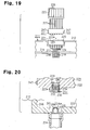
- Two plate springs 171b are arranged on the outer surface of a main body 172 of the transfer device 171, and recesses 120c are arranged in the two short side walls 120b forming the attaching portion 120.
- each plate spring 171b is engaged with the corresponding recess 120c, so that the transfer device 171 is elastically supported in the attaching portion 120.
- a valve mechanism 161 having substantially the same structure as the valve mechanism 161 of the fourth printer is arranged in the connection between each head side connection port 153a of the transfer device 171 and the corresponding first engagement hole 175 of the attaching portion 120. More specifically, the valve mechanism 161 includes a valve seat 162 arranged in the head side connection port 153a, a valve member 163, a spring 164, and an open/close dog 165 formed in the first engagement hole 175.
- the valve member 163 is pressed by the open/close dog 165 and spaced from the valve seat 162.
- the valve mechanism 161 opens, and the head side connection port 153a opens.
- a filter 166 is arranged in the supply liquid transfer passage 153 near the valve mechanism 161.
- a valve mechanism 141 having substantially the same structure as the valve mechanism 141 of the third printer is arranged in the connection between the pump side connection port 133a of the transfer device 171 and the second engagement hole 176 of the attaching portion 120. More specifically, the valve mechanism 141 includes a valve seat 142 arranged in the pump side connection port 133a, a valve member 143, a spring 144, and an open/close dog 145 projecting from the second engagement hole 176.
- the open/close dog 145 presses the valve member 143, and the valve member 143 is spaced from the valve seat 142.
- the valve mechanism 141 opens, and the pump side connection port 133a opens.
- the sixth printer has the advantages described below.
- each second supply duct 157 extending from the supply liquid tank 156 is connected to the corresponding first supply duct 154 extending from the recording head 118. Further, the second waste liquid duct 137 is connected to the first waste liquid duct 134 extending from the suction pump 129.
- each second supply duct 157 is disconnected from the corresponding first supply duct 154 and the second waste liquid duct 137 is disconnected from the first waste liquid duct 134. This facilitates replacement of the supply liquid tanks 156 and the waste liquid tank 135.
- the third to sixth printers may be modified as described below.
- valve units 119 are arranged in the recording head 118 and the six ink cartridges 121 are mounted on the frame 112 in the third embodiment, any number of valve units 119 and any number of ink cartridges 121 may be used.
- a printer for single color printing may include a single valve unit 119 and a single ink cartridge 121, and a printer for printing the four colors of black, cyan, magenta, and yellow may include four valve units 119 and four ink cartridges 121.
- the six valve units 119 are arranged on the recording head 118 and the six supply liquid tanks 156 are mounted on the tank holder 155 in the fourth to sixth embodiments.
- any number of valve units 119 and any number of supply liquid tanks 156 may be used.
- a printer for single color printing may include a single valve unit 119 and a single supply liquid tank 156.
- a printer for printing the four colors of black, cyan, magenta, and yellow may include four valve units 119 and four supply liquid tanks 156.
- the transfer device 131 for a waste liquid is attached to the attaching portion 120 in the rear portion of the frame 112 in a manner that the transfer device 131 is not removable.
- the transfer device 131 may be detachably attached to the attaching portion 120 in the same manner as the transfer device 171 of the sixth embodiment.
- the transfer device 151 for supply liquid is irremovably attached to the attaching portion 120 of the frame 112.
- the transfer device 151 may be detachably attached to the attaching portion 120 in the same manner as the transfer device 171 of the sixth embodiment.
- portions of the ducts 134, 137, 154, and 157 connected to the transfer devices 131, 151, and 171 may be formed from flexible tubes, and the remaining portions may be formed from a material other than flexible tubes.
- two distal portions of the ducts 134, 137, 154, and 157 may be formed from a rigid body made of metal such as stainless steel or hard synthetic resin, and intermediate portions between the two distal portions may be formed from flexible tubes.
- valve mechanisms 141 and 161 may be eliminated.
- a cap may be arranged to close the open end of the second waste liquid duct 137 or each second supply duct 157 when the second waste liquid duct 137 or the second supply duct 157 is disconnected from the transfer devices 131, 151, and 171.
- a valve that is actuated by an external operation to open and close the transfer passages 133 and 153 of the transfer devices 131, 151, and 171 may be arranged in the transfer passages 133 and 153.
- the valve is used to close the transfer passages 133 and 153 so that ink is prevented from leaking from the connection ports 133a, 133b, 153a, and 153b or the like when the second waste liquid duct 137 or the second supply duct 157 is removed from the transfer devices 131, 151, and 171.
- the inkjet printers 111 of the third to sixth printers may be replaced by liquid ejection apparatuses for ejecting liquid other than ink.
- the inkjet printer 111 may be a liquid ejection apparatus for ejecting liquids such as an electrode material or a color material used to manufacture, for example, liquid crystal display, an EL (electroluminescence) display, or an FED (field emission display); a liquid ejection apparatus for ejecting living organisms for use in manufacturing a biochip; or a sample ejection apparatus such as a precision pipette.
- a seventh printer forming an embodiment of the present invention, will now be described with reference to Figs. 16 to 18 .
- a platen 213 is arranged on an apparatus frame 212, and a paper feeding mechanism (not shown) feeds a paper P functioning as a print medium onto the platen 213.
- a guide member 214 is arranged on the apparatus frame 212 extending parallel to the platen 213, and a carriage 215 is movably supported on the guide member 214.
- the carriage 215 is operably linked to a carriage motor 217 by a timing belt 216.
- the carriage 215 reciprocates within a predetermined range along the guide member 214 when the carriage motor 217 is driven.
- a cover (not shown) opens and closes an upper portion of the apparatus frame 212 and covers a region above a moving range of the carriage 215.
- a recording head 218 functioning as an ejection head is mounted on a surface of the carriage 215 facing the platen 213.
- Six valve units 219 for supplying ink, which functions as liquid, to the recording head 218 are mounted on the carriage 215.
- the valve units 219 temporary contain predetermined amounts of six colors (six kinds) of ink used by the printer 211.
- the recording head 218 has a plurality of nozzles on its lower surface (not shown), and ink is ejected in dots from the nozzles onto the paper P, which functions as a target, to perform printing.
- an attaching portion 220 is defined by a recess formed in a rear portion of the apparatus frame 212.
- a transfer device 221 is irremovably attached to the attaching portion 220.
- a rear surface of the transfer device 221 is exposed from the apparatus frame 212.
- a plurality of transfer passages 223 are arranged in parallel at predetermined intervals in a main body 222 of the transfer device 221.
- a cylindrical head side connection port 223a is formed at a front end (downstream end) of each transfer passage 223 to project from the main body 222.
- a cylindrical tank side connection port 223b is formed at a rear end (upstream end) of each transfer passage 223 to project from the main body 222.
- a first duct 224 which is formed by a flexible tube, is connected and fixed to the head side connection port 223a of each transfer passage 223.
- Each first duct 224 has a distal end (downstream end) connected to the corresponding valve unit 219 of the recording head 218.
- Each valve unit 219 does not have to contain a predetermined amount of ink. In such a case, the first duct 224 is connected to an ink receiving side of the nozzles of the recording head 218.
- a tank 225 is arranged behind the apparatus frame 212.
- Six ink cartridges 226 having a large capacity are detachably accommodated within a tank case 225a of the tank 225.
- Each ink cartridge 226 contains different colors of ink.
- An upstream end of a second duct 227, which is formed by a flexible tube, is connected and fixed to each ink cartridge 226, and a downstream end of each second duct 227 is detachably connected to the tank side connection port 223b of the corresponding transfer passage 223 of the transfer device 221.
- a threaded portion 228 is formed on an outer circumference of each tank side connection port 223b of the transfer device 221, and a nut 229 is rotatably arranged on a distal end of each second duct 227 with a support tube 230 arranged in between.
- the nut 229 is mated with the threaded portion 228 so that each second duct 227 is detachably connected to the corresponding tank side connection port 223b.
- a valve mechanism 231 is arranged in a connection between each second duct 227 and the corresponding tank side connection port 223b.
- the valve mechanism 231 includes a valve seat 232 arranged in the support tube 230 of the second duct 227, a valve member 233 arranged to face the valve seat 232 in a manner that the valve member 233 can contact or be spaced from the valve seat 232, a spring 234 for urging the valve member 233 toward the valve seat 232, and an open/close dog 235 formed in the tank side connection port 223b to move the valve member 233.
- the open/close dog 235 has through-holes 235a that permit the passage of ink.
- the valve member 233 When the second duct 227 is connected to the tank side connection port 223b, the valve member 233 is pressed by the open/close dog 235 and spaced from the valve seat 232. As a result, the valve mechanism 231 opens. That is, the second duct 227 opens.
- the urging force of the spring 234 causes the valve member 233 to contact the valve seat 232 so that the valve mechanism 231 closes. That is, the second duct 227 closes.
- each second duct 227 is connected to the tank side connection port 223b of the transfer device 221
- the air pressure from a pressurizing pump (not shown) supplies ink from each ink cartridge 226 to the corresponding valve unit 219 of the recording head 218 through the corresponding second duct 227, the transfer device 221, and the corresponding first duct 224.
- a filter 236 is arranged in the tank side connection port 223b of each transfer passage 223.
- the filter 236 removes impurities, clots, or the like from the ink.
- a storage unit 237 is arranged on the main body 222 of the transfer device 221.
- the storage unit 237 stores attribute data including the identification number of the transfer device 221, the type of the transfer device 221, and the usable kinds of ink.
- a read device 238 functioning as a reading means is arranged on the attaching portion 220 in the apparatus frame 212 of the printer 211 in correspondence with the storage unit 237.
- the read device 238 reads the attribute data of the transfer device 221 from the storage unit 237, and stores the data in a memory of a controller 244 arranged on the apparatus frame 212.
- the controller 244 forms the reading means together with the read device 238.
- the controller 244 performs various processes including determination as to whether the attached transfer device 221 is appropriate based on the attribute data read from the read device 238.
- a nozzle protection unit 239 for protecting the nozzle function of the recording head 218 is arranged at a position corresponding to a home position of the recording head 218 in a region outside a print range at one side of the apparatus frame 212.
- the nozzle protection unit 239 includes a square box-shaped cap 240 having a top opening, an ink tube 241 extending from the bottom of the cap 240, a tube pump 242 arranged on the ink tube 241, and a waste ink tank 243 connected to one end of the ink tube 241.
- the cap 240 covers the nozzles of the recording head 218 to prevent the nozzles from drying.
- Ink absorbents (not shown) are arranged in the waste ink tank 243.
- the tube pump 242 is driven in a state in which the nozzles of the recording head 218 are covered by the cap 240, highly viscous ink, dust, and the like in the vicinity of the nozzles of the recording head 218 are discharged to the waste ink tank 243 through the ink tube 241 and stored in the waste ink tank 243 in a state absorbed in the absorbents.
- the distal end of the second duct 227 extending from the ink cartridge 226 on the tank case 225a, which is arranged behind the apparatus frame 212, is connected to the tank side connection port 223b of the transfer device 221.
- the carriage 215 moves along the guide member 214, and ink stored in each ink cartridge 226 is supplied to the corresponding valve unit 219 through the corresponding second duct 227, the transfer device 221, and the corresponding first duct 224 so that ink is ejected from the nozzles of the recording head 218 onto the paper P.
- the ink tank 225 having the ink cartridges 226 is arranged outside the apparatus frame 212.
- the capacity of the ink cartridges 226 is not limited by the accommodation space in the apparatus frame 212.
- ink may be continuously supplied to the recording head 218 without having to frequently replace the ink cartridges 226, and large-volume printing may be continuously performed.
- each first duct 224 is formed by a flexible tube.
- the first duct 224 easily bends as the recording head 218 moves when performing printing.
- the first duct 224 does not obstruct the movement of the recording head 218 or the supply of ink.
- the ink cartridge 226 When all of the ink in the ink cartridge 226 is consumed, the ink cartridge 226 must be replaced. In such a case, the nut 229 on the distal end of the second duct 227 extending from the empty ink cartridge 226 is removed from the threaded portion 228 of the tank side connection port 223b of the transfer device 221, and the second duct 227 is disconnected from the tank side connection port 223b. Afterwards, the empty ink cartridge 226 is removed from the tank case 225a, and a new ink cartridge 226, which is filled with ink, is mounted on the tank case 225a.
- a nut 229 on a distal end of a second duct 227 of the new ink cartridge 226 is mated with the threaded portion 228 of the tank side connection port 223b of the transfer device 221 to connect the second duct 227 to the tank side connection potion 223b.
- the second ducts 227 extending from the ink cartridges 226 via the transfer device 221 are connected to and disconnected from the first ducts 224 extending from the recording head 218.
- each second duct 227 is formed by a flexible tube.
- the second duct 227 can be easily connected to and disconnected from the corresponding tank side connection port 223b of the transfer device 221 wherever the ink cartridges 226 are arranged behind the apparatus frame 212. This facilitates the replacement of the ink cartridges 226.
- valve mechanism 231 is arranged in a connection between the distal end of each second duct 227 and the corresponding tank side connection port 223b of the transfer device 221.
- the valve mechanism 231 is closed when the connection is disconnected.
- the ink is prevented from leaking when the ink cartridge 226 is replaced.
- This embodiment has the advantages described below.
- the transfer device 221 arranged on the apparatus frame 212 of the printer 211 has the transfer passages 223.
- the head side connection port 223a is arranged on one end of each transfer passage 223.
- the tank side connection port 223b is arranged on the other end of each transfer passage 223.
- the recording head 218 is connected to the head side connection port 223a, and each cartridge 226 of the tank 225 is connected to the corresponding tank side connection port 223b. This ensures connection of the tank 225 and the recording head 218 by way of the transfer device 221 without the need for processing the ink cartridges 226 or form joints for enabling such connection. Further, ink is smoothly supplied to the recording head 218 through the transfer passage 223 from the tank 225 when the tank 225 and the recording head 218 are connected to each other.
- the tank 225 to have a large capacity irrespective of the size or the shape of the printer 211. Further, the tank 225 is not directly connected to the recording head 218. Thus, the closing of a cover (not shown) of the printer 211 is not obstructed by any ducts extending between the tank 225 and the recording head 218. As a result, the cover effectively prevents dust from entering the printer 211, and the aesthetic appeal of the printer 211 is not adversely affected. Further, as long as the transfer device 221 is arranged in the attaching portion 220, excessive force is not applied to the first ducts 224 or the like between the transfer device 221 and the recording head 218 when the recording head 218. reciprocates.
- the weight on the carriage 215 does not significantly change. This eliminates adverse effects on the movement of the carriage 215 that would be caused by such an attachment. Accordingly, printing is performed with high-quality.
- the transfer device 221 has the plurality of transfer passages 223, which may supply different kinds of ink separately to the plurality of nozzles of the recording head 218.
- the transfer device 221 is optimal for use in the inkjet printer 211.
- the filter 236 is arranged in each transfer passage 223, and the filter 236 removes impurities and the like from ink in the supply passage to the recording head 218. This prevents the recording head 218 from being clogged.
- the transfer device 221 has the storage unit 237, which may be used to preset and manage the attributes of the transfer device 221, such as the identification number and the type of the transfer device 221.
- the transfer device 221 is used as the ink passage of the printer 211, the usable types of ink or the like may be effectively managed.
- the structure including the nut 229 that is detachably connected to each second duct 227 extending from the tank 225 is arranged on the corresponding tank side connection port 223b of the transfer device 221.
- the second duct 227 is easily connected to and disconnected from the tank side connection port 223b, and the second duct 227 remains connected to the tank side connection port 223b in a satisfactory manner.
- the valve mechanism 231 which closes when the second duct 227 is disconnected, is arranged in the tank side connection port 223b.
- the ink is prevented from leaking from the tank side connection port 223b when the second duct 227 is disconnected to replace the tank 225.
- the first ducts 224 and second ducts 227 are formed by flexible tubes. Thus, the first ducts 224 and the second ducts 227 are easily bent as the recording head 218 moves. Thus, the first duct 224 and the second duct 227 do not obstruct the movement of the recording head 218 or the supply of liquid.
- the printer 211 includes the read device 238 and the controller 244, which form the reading means for reading the storage content of the storage unit 237 arranged in the transfer device 221.
- the read device 238 and the controller 244 may be used to identify the attributes of the transfer device 221 so that the attaching status of the transfer device 221 may be managed.
- the attaching portion 220 on which the transfer device 221 is attached is formed by a recess, and the transfer device 221 is attached to the attaching portion 220.
- the transfer device 221 does not project greatly out of the apparatus frame 212, and the aesthetic appeal of the printer 211 is maintained in a satisfactory state.
- the attaching portion 220 is arranged in the rear portion of the apparatus frame 212 of the printer 211.
- the transfer device 221 is not exposed from the front of the printer 211, and the aesthetic appeal of the printer 211 is maintained in a satisfactory state.
- Each second duct 227 which is formed by a flexible tube, may be connected to and disconnected from the corresponding tank side connection port 223b.
- the flexible tube may be bent and flexed so that the tank 225 can be easily connected to and disconnected from the tank side connection ports 223b to facilitate the replacement of the tank 225.
- the tank 225 may be arranged at any position outside the printer 221.
- a transfer device 221 is detachably attached to an attaching portion 220 defined by a recess formed in a rear portion of an apparatus frame 212.
- the transfer device 221 has a rear surface exposed from the apparatus frame 212.
- a spring 247 is arranged on the transfer device 221, and a recess 246 is formed in the attaching portion 220 for elastically supporting the transfer device 221 in the attaching portion 220. The spring 247 and the recess 246 are engaged with each other.
- a plurality of engagement holes 245, each including an open/close dog 235, are formed at predetermined intervals in the attaching portion 220, and a first duct 224 extending from a valve unit 219 of a recording head 218 is connected to each engagement hole 245.
- each head side connection port 223a of the transfer device 221 is engaged with and connected to the corresponding engagement hole 245 of the attaching portion 220.
- the transfer device 221 is attached to the attaching portion 220 so that the head side connection ports 223a are engaged with the engagement holes 245 and connected to the first ducts 224.
- a sealing means such as a seal ring (not shown), is arranged between an outer circumferential surface of the head side connection port 223a and an inner circumferential surface of the engagement hole 245 to prevent leakage of ink.
- valve mechanism 231 having substantially the same structure as the valve mechanism 231 of the seventh printer is arranged in the connection between each head side connection port 223a of the transfer device 221 and the corresponding engagement hole 245 of the attaching portion 220. More specifically, the valve mechanism 231 includes a valve seat 232 formed in the head side connection port 223a, a valve member 233 arranged to face the valve seat 232 in a manner that the valve member 233 can contact or be spaced from the valve seat 232, a spring 234 for urging the valve member 233 toward the valve seat 232, and an open/close dog 235 arranged in the engagement hole 245 for moving the valve member 233.
- valve member 233 When the head side connection port 223a is engaged with and connected to the engagement hole 245, the valve member 233 is pressed by the open/close dog 235 and spaced from the valve seat 232. This opens the valve mechanism 231. When the head side connection port 223a is disconnected from the engagement hole 245, the urging force of the spring 234 causes the valve member 233 to contact the valve seat 232. This closes the valve mechanism 231.
- each second duct 227 extending from the ink cartridge 226 is easily connected to and disconnected from the corresponding first duct 224 extending from the recording head 218 by attaching and detaching the transfer device 221 to and from the attaching portion 220 of the apparatus frame 212.
- the ink cartridge 226 is easily replaced.
- each valve mechanism 231 is closed.
- ink is prevented from leaking when the ink cartridges 226 are replaced.
- This embodiment has the advantages described below in addition to the advantages of the seventh printer.
- the transfer device 221 can be attached to and detached from the attaching portion 220.
- Each head side connection port 223a of the transfer device 221 can be connected to and disconnected from the corresponding first duct 224.
- detachment and attachment of the transfer device 221 on the attaching portion 220 facilitates replacement of the tank 225.
- the transfer device 221 can be attached to and detached from the apparatus frame 212 of the printer 211.
- each head side connection port 223a of the transfer device 221 is connected to the corresponding first duct 224.
- the recording head 218 and the tank 225 is easily disconnected by removing the transfer device 221 from the apparatus frame 212. This facilitates the replacement of the tank 225.
- the transfer device 221 is partially exposed when the transfer device 221 is attached to the attaching portion 220. Thus, the transfer device 221 is easily attached or detached by holding the exposed portion of the transfer device 221.
- the valve mechanism 231 which closes when the first duct 224 is disconnected from the transfer device 221, is arranged in the connection between each first duct 224 and the transfer device 221. Thus, ink is prevented from leaking when the transfer device 221 is removed from the apparatus frame 212.
- the seventh and eighth printers may be modified in the following forms.
- valve units 219 are arranged on the recording head 218 and the six ink cartridges 226 are mounted on the tank 225 in the seventh and eighth printers, any number of valve units 219 and any number of ink cartridges 226 may be used.
- the location of the attaching portion 220 of the transfer device 221 may be changed from the rear portion of the apparatus frame 212 to another position such as a side portion or a lower portion of the apparatus frame 212.
- each first duct 224 and each second duct 227 may be made of metal, such as stainless steel, and the intermediate portion between the two distal portions may be formed by a flexible tube.
- the first duct 224 and the second duct 227 are further firmly connected to the transfer device 221, and ink is prevented from being degraded by gas transmitted through the flexible tubes.
- a valve mechanism that is operable by an external device may be arranged in the outlet of each ink cartridge 226.
- the outlet of the ink cartridge 226 may be closed when the tank 225 is replaced to prevent the ink from leaking.
- the ink cartridges 226 may be arranged at positions higher than the recording head 218, and the height difference may be used to supply ink from the ink cartridges 226 to the recording head 218.
- the inkjet printers 211 of the seventh and eighth printers may be replaced by liquid ejection apparatuses for ejecting liquids other than ink.
- the inkjet printer 211 may be a liquid ejection apparatus for ejecting liquids such as an electrode material or a color material used to manufacture, for example, liquid crystal display, an EL display, or an FED (field emission display); a liquid ejection apparatus for ejecting living organisms for use in manufacturing a biochip; or a sample ejection apparatus as a precision pipette.
Landscapes
- Engineering & Computer Science (AREA)
- Environmental & Geological Engineering (AREA)
- Ink Jet (AREA)
- Physical Water Treatments (AREA)
Abstract
Description
- The present invention relates to a transfer device for connecting an ejection head and a tank storing liquid supplied to the ejection head, and to a liquid ejection apparatus including the transfer device.
- An inkjet printer is known as liquid ejection apparatus having liquid ejection mechanism for ejecting liquid in dots from nozzles of an ejection head. The inkjet printer may be either a printer having an on-carriage ink supply system in which an ink cartridge is mounted on a carriage or a printer having an off-carriage ink supply system in which an ink cartridge is mounted at a position separated from a carriage such as on a main body of the printer. A printer of the off-carriage ink supply system may use a large-capacity ink cartridge to print large-volume data or to perform printing on large-sized paper. Further, without having to mount an ink cartridge on its carriage, the printer of the off-carriage ink supply system can downsize the carriage and prevent the size of the entire printer from increasing.
- However, the printer of the off-carriage ink supply system requires its ink cartridge to be mounted in a limited space within the frame of the printer. This limits the capacity of the ink cartridge. Thus, to continuously print a large volume of printed matter, the ink cartridge must be frequently replaced. Such work is troublesome.
-
Patent documents 1 and 2 disclose ink supply apparatuses that have been proposed to overcome such a problem. In the ink supply apparatus ofpatent document 1, a tank having a plurality of ink supply cartridges on its base is arranged outside the printer. An ink supply duct is connected to each ink supply cartridge. The ink supply ducts are connected to the ink cartridges of the printer so as to automatically supply ink from the ink supply cartridges to the ink cartridges of the printer via the ink supply ducts. - In the ink supply apparatus of patent document 2, instead of an ink cartridge, an attachment is attached to a carriage of a printer, and ink is supplied from an external ink tank to the attachment.
- In the printers of these types, an apparatus for drawing in waste ink is arranged in a region outside the print range (at a location corresponding to the home position of the recording head) at one side of the frame to prevent ink from drying and hardening in the nozzle portion of the recording head, which functions as an ejection head. This waste ink suction apparatus includes a suction pump and a waste liquid tank connected to the suction pump by a duct. Ink is drawn in from the nozzles of the recording head by the suction pump, and the ink is collected in the waste liquid tank as waste liquid.
- However, in a printer employing such a waste ink suction apparatus, the waste liquid tank is arranged in a limited space within the frame. This limits the collection capacity of the waste liquid. Thus, even when the printer includes the ink supply apparatus of the above-described
patent document 1 or patent document 2 to continuously print a large volume of printed matter, the limited capacity of the waste ink suction apparatus that collects the waste liquid makes it difficult to perform large-volume printing. - The ink supply apparatus of
patent document 1, which requires the ink supply ducts to be connected to the ink cartridges of the printer, has the problem described below. - When the printer uses the off-carriage ink supply system, the distal end of each ink supply duct must be directly connected to the corresponding ink cartridge on the printer. However, the structure of the ink cartridge is not applicable for such connection. Thus, for example, the user is required to process the ink cartridge in order to connect the ink duct to the ink cartridge. Such preprocessing for the connection is extremely troublesome.
- The ink supply apparatus of
patent document 1 used in a printer of the on-carriage ink supply system also requires each ink supply duct to be connected to the corresponding ink cartridge on the carriage, and the preprocessing for enabling the connection is as troublesome as in the case of the off-carriage ink supply system. - Further, the ink supply system of patent document 2 has the attachment mounted on the carriage instead of the ink cartridge as described above, and a tube extending from the ink tank is connected to the attachment. However, in the ink supply system of patent document 2, the weight held by the carriage greatly differs from the weight held when an ink cartridge is mounted on the carriage. This may adversely affect the operation of the carriage and lower the printing quality. Further, the tube, which extends from the ink tank that is arranged outside the printer, is connected to the cartridge on the carriage in the structure of patent document 2. Thus, the tube may be an obstruction when closing a cover, which is located above a carriage moving region. As a result, dust may easily enter the printer, and the aesthetic appeal of the printer may be lowered. In particular, the carriage reciprocates in a state in which the tube is connected to the attachment on the carriage in the structure of patent document 2. Thus, the tube is also moved whenever the carriage reciprocates. In this case, if the external ink tank is installed at an improper position, the movement of the carriage may forcibly pull or bend the tube. This may consequently generate excessive load when the carriage moves or interfere with the smooth supply of ink. In such a case, this would hinder high-quality printing.
- Patent Document 1: Chinese Registered Utility Model Publication No. CN 2355886
- Patent Document 2: Japanese Laid-Open Patent Publication No. 2003-326732
- US 2003/0176005 discloses a connection between a sub-tank and a main tank of a liquid droplet ejecting apparatus. The preamble of
claim 1 is based on this document. - A first object of the present invention is to provide a waste liquid collection apparatus that enables a waste liquid tank to have a large capacity and to provide a liquid ejection apparatus including the waste liquid collection apparatus. A second object of the present invention is to provide a transfer device for enabling easy connection to a waste liquid tank and to provide a liquid ejection apparatus including the transfer device. A third object of the present invention is to provide a transfer device for ensuring simple connection of an ejection head and a tank storing liquid supplied to the ejection head without causing any of the problems described above and to provide a liquid ejection apparatus including the transfer device.
- To achieve the first object, there is disclosed a waste liquid collection apparatus for use in a state arranged outside a liquid ejection mechanism. The waste liquid collection apparatus has a waste liquid tank including a connection port connectable to a discharge side of a suction pump that draws in liquid from a nozzle of an ejection head arranged in the liquid ejection mechanism.
- There is also disclosed a liquid ejection apparatus. The liquid ejection apparatus has a liquid ejection mechanism including an ejection head for ejecting liquid from a nozzle and a suction pump for drawing in liquid from the nozzle of the ejection head when the ejection head is not ejecting liquid, and the above waste liquid collection apparatus.
- To achieve the second object, there is disclosed a transfer device including a waste liquid transfer passage having an upstream end and a downstream end. The upstream end of the waste liquid transfer passage includes a pump side connection port connected to a discharge side of a suction pump for drawing in liquid from a nozzle of an ejection head, and the downstream end of the waste liquid transfer passage includes a discharge port for discharging the liquid drawn in by the suction pump.
- There is also disclosed a liquid ejection apparatus. The liquid ejection apparatus includes an ejection head for ejecting liquid, and a suction pump for drawing in liquid from a nozzle of the ejection head. The suction pump has a discharge side connected by a duct to the pump side connection port of the above transfer device.
- To achieve the third object, the present invention provides a transfer device as recited in the claims including a transfer passage having an upstream end and a downstream end. The upstream end of the transfer passage includes a tank side connection port connected to a duct extending from a tank containing liquid, and the downstream end of the transfer passage includes a head side connection port connected to a duct extending from an ejection head for ejecting liquid supplied from the tank. The transfer device includes a storage unit for storing data on an attribute of the transfer device.
- The present invention further provides a liquid ejection apparatus. The liquid ejection apparatus includes an ejection head for ejecting liquid onto a target, and an apparatus frame including an attaching portion. The above transfer device is attached to the attaching portion, and the head side connection port of the transfer device is connected by a duct to the ejection head. The liquid ejection apparatus includes a reading means for reading a content of the storage unit of the transfer device.
-
-
Fig. 1 is a schematic perspective view of a first printer system; -
Fig. 2 is an enlarged perspective view of a printer included in the printer system ofFig. 1 ; -
Fig. 3 is an enlarged cross-sectional view of an essential part of the printer ofFig. 2 showing an ink suction apparatus and a waste liquid collection apparatus; -
Fig. 4 is an enlarged exploded cross-sectional view of an essential part of the waste liquid collection apparatus ofFig. 3 showing a valve mechanism of a transfer device; -
Fig. 5 is a schematic plan view of a second printer system; -
Fig. 6 is an enlarged cross-sectional view of a part of a printer included the printer system ofFig. 5 showing a transfer device; -
Fig. 7 is an enlarged exploded cross-sectional view of an essential part of the transfer device ofFig. 6 showing a valve mechanism; -
Fig. 8 is a perspective view of a third printer; -
Fig. 9 is an enlarged cross-sectional view of an essential part of the printer ofFig. 8 showing a waste ink suction apparatus; -
Fig. 10 is an enlarged exploded cross-sectional view of an essential part of the waste ink supply apparatus ofFig. 9 showing a valve mechanism of a transfer device; -
Fig. 11 is a partial plan view of a fourth printer; -
Fig. 12 is an enlarged exploded cross-sectional view of an essential part of the printer ofFig. 11 showing a valve mechanism of a transfer device; -
Fig. 13 is a partial plan view of a fifth printer; -
Fig. 14 is a partial plan view of a sixth printer; -
Fig. 15 is an enlarged exploded cross-sectional view of an essential part of the printer ofFig. 14 showing a valve mechanism of a transfer device; -
Fig. 16 is a perspective view of a seventh printer according to an embodiment of the present invention; -
Fig. 17 is an enlarged cross-sectional view of an essential part of the printer ofFig. 16 showing a transfer device; -
Fig. 18 is an enlarged exploded cross-sectional view of an essential part of the transfer device ofFig. 17 showing a valve mechanism; -
Fig. 19 is a partial plan view of an eighth printer according to an embodiment of the present invention; and -
Fig. 20 is an enlarged exploded cross-sectional view of an essential part of the printer ofFig. 19 showing a valve mechanism of a transfer device. - The printers of
Figures 1 to 15 are not disclosed to include a storage unit and reading means as recited in the claims and thus do not form embodiments of the present invention. - A first embodiment of the present invention will now be described with reference to
Figs. 1 to 4 . - As shown in
Fig. 1 , a first printer system serving as a liquid ejection system includesinkjet printers 11 functioning as a plurality of liquid ejection apparatuses arranged in parallel. A singlewaste liquid tank 35 forming a waste liquid collection apparatus is arranged behind theprinters 11. A plurality of secondwaste liquid ducts 37 extend from thewaste liquid tank 35. Each secondwaste liquid duct 37 has a distal end detachably connected to atransfer device 31 for waste liquid arranged in a rear portion of the correspondingprinter 11. - As shown in
Fig. 2 , in eachprinter 11, aplaten 13 is arranged on aframe 12, and a paper feeding mechanism (not shown) feeds a paper P, which functions as a print medium, onto theplaten 13. Aguide member 14 is arranged on theframe 12 to extend in parallel to theplaten 13, and acarriage 15 is movably supported on theguide member 14. Thecarriage 15 is operably connected to a carriage motor 17 by atiming belt 16. Thecarriage 15 reciprocates within a predetermined range along theguide member 14 when the carriage motor 17 is driven. - A
recording head 18, which functions as an ejection head that forms a liquid ejection mechanism, is mounted on the surface of thecarriage 15 facing theplaten 13. Sixvalve units 19 for supplying ink, which functions as a liquid, to therecording head 18 are mounted on thecarriage 15. Thevalve units 19 temporary store six colors (six kinds) of ink used in theprinter 11. Therecording head 18 has a plurality of nozzles arranged on its lower side (not shown), and ink is ejected in dots from the nozzles onto the paper P, which functions as a target, through thevalve units 19 to perform printing. - As shown in
Fig. 2 , a first attachingportion 20A and a second attachingportion 20B are defined by recesses in the rear portion of theframe 12. Sixink cartridges 21 are detachably attached to one side of the first attachingportion 20A. Theink cartridges 21 contain different colors of ink. Asupply duct 22, which is formed by a flexible tube, is connected to eachink cartridge 21. Eachsupply duct 22 has a distal end connected to thecorresponding valve unit 19 of therecording head 18. The air pressure generated by a pressurizing pump (not shown) supplies ink from eachink cartridge 21 to thecorresponding valve unit 19 of therecording head 18 through thecorresponding supply duct 22. - As shown in
Figs. 2 and3 , anink suction apparatus 25 for drawing in ink from the nozzles of therecording head 18 is arranged at a location corresponding to a home position of therecording head 18 at one side of theframe 12 in a region that is outside a print range. Theink suction apparatus 25 includes a flat and substantially square box-shape cap 26, which has an open top surface, anink tube 27, which extends from the bottom of thecap 26, acheck valve 28, which is arranged near the inlet of theink tube 27, and asuction pump 29, which is a tube pump forming part of the liquid ejection mechanism near the outlet of theink tube 27. An absorbent (sponge) 30 containing ink is arranged in thecap 26. Thecarriage 15 is moved to the home position when printing is suspended, and a drive means (not shown) raises thecap 26 to cover the nozzles of therecording head 18. This prevents the ink remaining in the nozzles from drying. - As shown in
Figs. 2 and3 , thetransfer device 31 for waste liquid is detachably attached to the second attachingportion 20B of theframe 12. Thetransfer device 31 has a rear surface exposed from theframe 12. Further, thetransfer device 31 has a square block-shapedmain body 32. A wasteliquid transfer passage 33 is formed in themain body 32. A cylindrical pumpside connection port 33a, which is located at the front end of the wasteliquid transfer passage 33, projects from themain body 32. Acylindrical discharge port 33b, which is located at the rear end of the wasteliquid transfer passage 33, projects from themain body 32. The pumpside connection port 33a is connected to the suction pump 29 (more specifically, to the discharge side of the suction pump 29) by a firstwaste liquid duct 34, which is formed by a flexible tube. - The
waste liquid tank 35 forming a waste liquid collection apparatus is arranged behind theframe 12 outside theframe 12, andink absorbents 36 are stacked in thewaste liquid tank 35. The secondwaste liquid duct 37, which extends from thewaste liquid tank 35, is formed by a flexible tube. The secondwaste liquid duct 37 has a distal end forming aconnection port 37a (in other words, aconnection port 37a of the waste liquid tank 35) that is detachably connected to thedischarge port 33b of thetransfer device 31. In more detail, as shown, inFigs. 3 and4 , a threadedportion 38 is formed on an outer circumference of thedischarge port 33b of thetransfer device 31, and anut 39 is rotatably attached to theconnection port 37a, which functions as a head side connection port of the secondwaste liquid duct 37, with asupport tube 40 arranged in between. Thenut 39 is mated with the threadedportion 38 so that theconnection port 37a of the secondwaste liquid duct 37 is detachably connected to thedischarge port 33b of thetransfer device 31. - A
valve mechanism 41 functioning as a closing means is arranged in the connection between thedischarge port 33b of thetransfer device 31 and theconnection port 37a of the secondwaste liquid duct 37. Thevalve mechanism 41 includes avalve seat 42 arranged in thesupport tube 40, avalve member 43 arranged to face thevalve seat 42 so that thevalve member 43 can be in contact with or spaced from thevalve seat 42, aspring 44 for urging thevalve member 43 toward thevalve seat 42, and an open/close dog 45 having throughholes 45a and formed on thedischarge port 33b of thetransfer device 31 to move thevalve member 43. When theconnection port 37a of the secondwaste liquid duct 37 is connected to thedischarge port 33b of thetransfer device 31, thevalve member 43 is pressed by the open/close dog 45 and spaced from thevalve seat 42. This opens thevalve mechanism 41. That is, theconnection port 37a of the secondwaste liquid duct 37 opens. When theconnection port 37a is disconnected from thedischarge port 33b, the urging force of thespring 44 causes thevalve member 43 to contact thevalve seat 42 and closes thevalve mechanism 41. That is, theconnection port 37a of the secondwaste liquid duct 37 closes. - When the
cap 26 covers the nozzles of therecording head 18 and thesuction pump 29 is driven while theconnection port 37a of the secondwaste liquid duct 37 is connected to thedischarge port 33b of thetransfer device 31, highly viscous ink, dust, and the like in the vicinity of the nozzles of therecording head 18 are drawn into theink tube 27 by thesuction pump 29. The drawn in ink and the like are discharged to thewaste liquid tank 35 as a waste liquid through the firstwaste liquid duct 34, the wasteliquid transfer passage 33, and the secondwaste liquid duct 37 and collected in thewaste liquid tank 35 in a state absorbed in theabsorbents 36. - The operation of the
printer 11 including the waste liquid collection apparatus with the above-described structure will now be described. - In the states shown in
Figs. 2 and3 , theconnection port 37a at the distal end of the secondwaste liquid duct 37 expending from thewaste liquid tank 35, which is arranged behind theframe 12, is connected to thedischarge port 33b of thetransfer device 31. When theprinter 11 performs a printing operation in this state, thecarriage 15 moves along theguide member 14, and the ink stored in eachink cartridge 21 is supplied to thecorresponding valve unit 19 by the correspondingsupply duct 22 so that ink is ejected from the nozzles of therecording head 18 onto the paper P to perform printing. - When the printing operation of the
printer 11 is suspended, thecarriage 15 moves to the home position that corresponds to thecap 26 of theink suction apparatus 25. Then, thecap 26 covers the nozzles of therecording head 18 as shown inFig. 3 to prevent the nozzles from drying. - When a switch for cleaning the nozzles of the
recording head 18 is operated, a predetermined timing is reached during printing, or theink cartridge 21 is replaced, thecarriage 15 moves to the home position and thecap 26 covers the nozzles of therecording head 18 in the same manner as when the printing operation is suspended. - When the
suction pump 29 is driven in a state in which the nozzles are covered by thecap 26, highly viscous ink, dust, and the like in the vicinity of the nozzles are drawn in, and the drawn in ink and the like are discharged to thewaste liquid tank 35 via the firstwaste liquid duct 34, the wasteliquid transfer passage 33, and the secondwaste liquid duct 37 and collected in thewaste liquid tank 35 in a state absorbed in theabsorbents 36. - In the present embodiment, the
waste liquid tank 35 is arranged outside theframe 12 of theprinter 11. Thus, the capacity of thewaste liquid tank 35 is not limited by the accommodation space in theframe 12. Accordingly, when thewaste liquid tank 35 having a large capacity is used, the waste liquid drawn in from the nozzles of therecording head 18 by thesuction pump 29 can be continuously collected in thewaste liquid tank 35. - When the
waste liquid tank 35 becomes full with waste liquid, thewaste liquid tank 35 must be replaced. In such a case, thenut 39 on the distal end of the secondwaste liquid duct 37 extending from thewaste liquid tank 35, which has become full, is removed from the threadedportion 38 of thedischarge port 33b of thetransfer device 31. Then, theconnection port 37a on the distal end of the secondwaste liquid duct 37 is disconnected from thedischarge port 33b. Afterwards, thewaste liquid tank 35 that is full is replaced with another empty waste liquid tank, and a nut on a distal end of a second waste liquid duct extending from the empty waste liquid tank is mated with the threadedportion 38 of thedischarge port 33b of thetransfer device 31. Then, aconnection port 37a of the second waste liquid duct is connected to thedischarge port 33b. - As described above, in the present embodiment, the second
waste liquid duct 37 extending from thewaste liquid tank 35 via thetransfer device 31 is connected to and disconnected from the firstwaste liquid duct 34 extending from the discharge side of thesuction pump 29. Thewaste liquid ducts waste liquid tank 35. Further, the secondwaste liquid duct 37 is formed by a flexible tube. Thus, the secondwaste liquid duct 37 is easily connected to or disconnected from thedischarge port 33b of thetransfer device 31 and the replacement of thewaste liquid tank 35 is facilitated wherever thewaste liquid tank 35 is located behind theframe 12. Further, thevalve mechanism 41 is arranged in the connection between theconnection port 37a of the secondwaste liquid duct 37 and thedischarge port 33b of thetransfer device 31, and thevalve mechanism 41 closes when the connection is disconnected. Thus, the waste liquid is prevented from leaking when thewaste liquid tank 35 is replaced. - The first printer system has the advantages described below.
- The large-capacity
waste liquid tank 35 is arranged at outside the plurality ofprinters 11, and thewaste liquid tank 35 is connected to thesuction pump 29 of eachprinter 11. As a result, the ink drawn in from the nozzles of therecording head 18 is continuously collected in thewaste liquid tank 35 so that large-volume printing can be continuously performed. Further, only onewaste liquid tank 35 is arranged for the plurality ofprinters 11, the entire system may be miniaturized and the structure may be simplified. Further, eachprinter 11 does not need to include thewaste liquid tank 35. This enables the size of eachprinter 11 to be reduced. - The
connection port 37a of the secondwaste liquid duct 37 of thewaste liquid tank 35 is connected to or disconnected from thedischarge port 33b of thetransfer device 31, that is, the discharge side of thesuction pump 29, so that thewaste liquid tank 35 can be easily connected to or disconnected from the discharge side of thesuction pump 29. Thus, thewaste liquid tank 35 can be replaced easily. - The
connection port 37a of thewaste liquid tank 35 is arranged at the distal end of the secondwaste liquid duct 37, which is formed by a flexible tube (in other words, the secondwaste liquid duct 37 is formed by a flexible tube). Thus, the flexible tube can be bent, and thewaste liquid tank 35 can be arranged at any position outside theprinter 11 and theconnection port 37a of the secondwaste liquid duct 37 and be easily connected to thedischarge port 33b of thetransfer device 31. - The
valve mechanism 41 for opening theconnection port 37a when the secondwaste liquid duct 37 is connected to thetransfer device 31 and closing theconnection port 37a when the secondwaste liquid duct 37 is disconnected from thetransfer device 31 is arranged in theconnection port 37a of the secondwaste liquid duct 37. Thus, the ink is prevented from leaking when thewaste liquid tank 35 is replaced by disconnecting theconnection port 37a from thedischarge port 33b of thetransfer device 31. - A second printer system will now be described focusing on differences from the first printer system.
- A second printer system does not include the
ink cartridges 21 of the first printer system as shown inFigs. 5 to 7 . Further, an attachingportion 20 is arranged at a rear portion of aframe 12 in lieu of the first attachingportion 20A and the second attachingportion 20B in the first embodiment. Atransfer device 51 used commonly for the supplied liquid and the waste liquid is detachably attached to the attachingportion 20 in lieu of thetransfer device 31 for waste liquid in the first embodiment. A rear surface of thetransfer device 51 is exposed from theframe 12. A single wasteliquid transfer passage 33 that is the same as that in the first embodiment and a plurality of supplyliquid transfer passages 53 are formed in parallel at predetermined intervals within amain body 52 of thetransfer device 51. A cylindrical pumpside connection port 33a is formed at a front end of the wasteliquid transfer passage 33 and projects from themain body 52. Acylindrical discharge port 33b is formed at a rear end of the wasteliquid transfer passage 33 and projects from themain body 52. The pumpside connection port 33a is connected to asuction pump 29 by a firstwaste liquid duct 34, which is formed by a flexible tube. A headside connection port 53a, which is cylindrical, is formed at a front end of each supplyliquid transfer passage 53 and project from themain body 52. A cylindrical tankside connection port 53b is formed at a rear end of each supplyliquid transfer passage 53 and projects from themain body 52. An upstream end of afirst supply duct 54, which is formed by a flexible tube, is connected and fixed to the headside connection port 53a of each supplyliquid transfer passage 53, and a downstream end of eachfirst supply duct 54 is connected to acorresponding valve unit 19 of arecording head 18. - A
tank holder 55, which is formed by a case, is arranged behind theframe 12. Thetank holder 55 accommodates awaste liquid tank 35 that is the same as that in the first embodiment and six large-capacitysupply liquid tanks 56 containing different colors of ink in a manner that each tank is removable independently. More specifically, thetanks tank holder 55. A downstream end of a secondwaste liquid duct 37, which is formed by a flexible tube, is connected and fixed to thewaste liquid tank 35, and an upstream end of each secondwaste liquid duct 37 is detachably connected to thedischarge port 33b of the wasteliquid transfer passage 33 of thecorresponding transfer device 51. An upstream end of asecond supply duct 57, which is formed by a flexible tube, is connected and fixed to eachsupply liquid tank 56, and a downstream end of eachsecond supply duct 57 is detachably connected to the tankside connection port 53b of the corresponding supplyliquid transfer passage 53 of thetransfer device 51. In more detail, in the same manner as the connection between eachtransfer device 31 and the corresponding secondwaste liquid duct 37 in the first embodiment, a threadedportion 38 formed on an outer circumference of thedischarge port 33b is mated with anut 39 rotatably attached to a distal end of the secondwaste liquid duct 37 with asupport tube 40 arranged in between. A threadedportion 58 formed on an outer circumference of the tankside connection port 53b is mated with anut 59 rotatably attached to a distal end of eachsecond supply duct 57 with asupport tube 60 arranged in between. Thus, the secondwaste liquid duct 37 is detachably connected to thedischarge port 33b, and eachsecond supply duct 57 is detachably connected to the corresponding tankside connection port 53b. - A
valve mechanism 61 functioning as a closing means is arranged in a connection between eachsecond supply duct 57 and the corresponding tankside connection port 53b. Thevalve mechanism 61 includes avalve seat 62 arranged in thesupport tube 60 of thesecond supply duct 57, avalve member 63, aspring 64, and an open/close dog 65 having through-holes 65a formed on the tankside connection port 53b in the same manner as thevalve mechanism 41 of the first embodiment. When thesecond supply duct 57 is connected to the tankside connection port 53b (in other words, when thesupply liquid tank 56 is connected to the recording head 18), thevalve member 63 is pressed by the open/close dog 65 and spaced from thevalve seat 62. As a result, thevalve mechanism 61 opens. That is, thesecond supply duct 57 opens. When thesecond supply duct 57 is disconnected from the tankside connection port 53b (in other words, when thesupply liquid tank 56 is disconnected from the recording head 18), the urging force of thespring 64 causes thevalve member 63 to contact thevalve seat 62. This closes thevalve mechanism 61. More specifically, thesecond supply duct 57 closes. Avalve mechanism 41 that is the same as that in the first embodiment is arranged in the connection between the secondwaste liquid duct 37 and thedischarge port 33b. - A
filter 66 is arranged in each tankside connection port 53b so that thefilter 66 is located in the corresponding supplyliquid transfer passage 53. When eachsecond supply duct 57 is connected to the tankside connection port 53b of thetransfer device 51, the air pressure from a pressurizing pump (not shown) supplies ink from eachsupply liquid tank 56 to thecorresponding valve unit 19 of therecording head 18 through the correspondingsecond supply duct 57, thetransfer device 51, and the correspondingfirst supply duct 54. In this case, thefilter 66 removes impurities and the like from the ink in the supplyliquid transfer passage 53 of thetransfer device 51. - In the second printer system, the
supply liquid tanks 56 are arranged outside theframe 12 of theprinter 11. Thus, the capacity of thesupply liquid tanks 56 is not limited by the accommodation space in theframe 12. Whensupply liquid tanks 56 having a large capacity are used, ink can be supplied continuously to therecording head 18 without requiring thesupply liquid tanks 56 to be replaced frequently, and large-volume printing can be continuously performed. Further, eachfirst supply duct 54 is formed by a flexible tube. Thus, thefirst supply duct 54 easily bends as it follows the movement of therecording head 18 when printing is performed. Thus, thefirst supply duct 54 does not obstruct movement of therecording head 18 or the supply of ink. - Further, in the second printer system, the
waste liquid tank 35 and thesupply liquid tanks 56 are accommodated and supported in thetank holder 55 in a removable manner, and thewaste liquid tank 35 and thesupply liquid tanks 56 are integrated together in a state accommodated in thetank holder 55. Thus, thewaste liquid tank 35 and thesupply liquid tanks 56 may be arranged in a manner concentrated at one position. This facilitates the attachment, removal, and replacement of thetanks - When all of the ink in a
supply liquid tank 56 is consumed, thesupply liquid tank 56 must be replaced. In that case, thenut 59 on the distal end of thesecond supply duct 57 extending from thesupply liquid tank 56 is removed from the threadedportion 58 of the tankside connection port 53b of thetransfer device 51, and thesecond supply duct 57 is disconnected from thetransfer device 51. Afterwards, a nut on a distal end of a second supply duct extending from another supply liquid tank that is filled with ink is mated with the threadedportion 58 of the tankside connection port 53b of thetransfer device 51. In this manner, thesecond supply duct 57 and the tankside connection port 53b of thetransfer device 51 are easily connected and disconnected. Thus, the emptysupply liquid tank 56 is replaced with another supply liquid tank that is filled with ink. Further, eachsecond supply duct 57 is formed by a flexible tube. Thus, thesecond supply duct 57 can be easily connected to and disconnected from the tankside connection port 53b wherever thesupply liquid tanks 56 are arranged behind theframe 12. This facilitates the replacement of thesupply liquid tanks 56. Further, thevalve mechanism 61 is arranged in the connection between the distal end of thesecond supply duct 57 and the tankside connection port 53b of thetransfer device 51, and thevalve mechanism 61 closes when the connection is disconnected. Thus, the ink is prevented from leaking when thesupply liquid tank 56 is replaced. - The second printer system has the advantages described below in addition to the advantages of the first printer system.
- The second printer system includes the
supply liquid tanks 56, each of which contains a large amount of ink that is supplied to therecording head 18. Thus, the printer can continuously supply ink from thesupply liquid tanks 56 to therecording head 18 and continuously perform large-volume printing. - Each
second supply duct 57 between thesupply liquid tank 56 and thetransfer device 51 is formed by a flexible tube. Thus, the flexible tube can be bent, and thesupply liquid tanks 56 can be arranged at any position. Further, thesupply liquid tanks 56 can be easily connected to thetransfer device 51. - The
valve mechanism 61, which opens when connected to thetransfer device 51 and closes when disconnected from thetransfer device 51, is arranged in the upstream end of thesecond supply duct 57. Thus, ink is prevented from leaking when thesupply liquid tank 56 is replaced. - The
waste liquid tank 35 and thesupply liquid tanks 56 are.detachably supported on thesingle tank holder 55. Thus, the entire tank may be miniaturized, and replacement of thewaste liquid tank 35 and thesupply liquid tanks 56 is facilitated. - The first and second printer systems may be modified as described below.
- Although six
valve units 19 are arranged on therecording head 18 and sixink cartridges 21 are mounted on theframe 12 in the first printer system, any number ofvalve units 19 and any number ofink cartridges 21 may be used. For example, a printer for single color printing may include asingle valve unit 19 and asingle ink cartridge 21, and a printer that performs printing with the four colors of black, cyan, magenta, and yellow may include fourvalve units 19 and fourink cartridges 21. - Although six
valve units 19 are arranged on therecording head 18 and sixsupply liquid tanks 56 are mounted on thetank holder 55 in the second embodiment, any number ofvalve units 19 and any number ofsupply liquid tanks 56 may be used. For example, a printer for single color printing may include asingle valve unit 19 and a singlesupply liquid tank 56, and a printer that performs printing with the four colors of black, cyan, magenta, and yellow may include fourvalve units 19 and foursupply liquid tanks 56. - In the first printer system, the
transfer device 31 may be detachably attached to the attachingportions frame 12. In this case, the pumpside connection port 33a projecting from the front surface of thetransfer device 31 must be detachable from the firstwaste liquid duct 34. - In the second printer system, the
transfer device 51 may be detachably attached to the attachingportion 20 at the rear portion of theframe 12. In this case, the headside connection port 53a projecting from the front surface of thetransfer device 51 must be detachable from thefirst supply duct 54. - In the second printer system, a transfer device for ink and a transfer device for a waste liquid may be attached to the attaching
portion 20 at the rear portion of theframe 12 instead of thetransfer device 51 commonly used for ink and waste liquid. - In the second printer system, the
supply liquid tanks 56 and thewaste liquid tank 35 are accommodated and supported in thesingle tank holder 55 in a removable manner. However, thetanks frame 12 of theprinter 11. - In the first and second printer systems, the printer system is formed by the
printers 11 that are independent from one another, and eachprinter 11 is connected to the singlewaste liquid tank 35 by aduct 37. However, the printer system may be formed by a plurality of printer mechanisms, each having a recording head and arranged on the same frame. Each printer mechanism may be connected to a singlewaste liquid tank 35 arranged behind the frame. - Instead of connecting more than one
printer 11 to thewaste liquid tank 35, only oneprinter 11 may be connected to thewaste liquid tank 35. - In the first and second printer systems, the pressurizing pump for supplying ink from the
supply liquid tanks 56 is used. However, ink may be supplied using height difference instead of using the pressurizing pump. - Portions of the
supply duct 22, the firstwaste liquid duct 34, the secondwaste liquid duct 37, thefirst supply duct 54, and thesecond supply duct 57 may be formed by flexible tubes, and the remaining portions may be formed from a rigid body made of metal such as stainless steel or hard synthetic resin. - The
valve mechanisms supply duct 22, the firstwaste liquid duct 34, the secondwaste liquid duct 37, thefirst supply duct 54, thesecond supply duct 57, the wasteliquid transfer passage 33, or the supplyliquid transfer passage 53 when the opening is exposed. In this case, the cap functions as a closing means. - The
inkjet printers 11 of the first and second printer systems may be replaced by liquid ejection apparatuses for ejecting liquids other than ink. For example, theinkjet printer 11 may be a liquid ejection apparatus for ejecting liquid such as an electrode material or a color material used to manufacture, for example, a liquid crystal display, an EL (electroluminescence) display, or an FED (field emission display); a liquid ejection apparatus for ejecting living organisms for use in manufacturing a biochip; or a sample ejection apparatus such as a precision pipette. - A third printer will now be described with reference to
Figs. 8 to 10 . - As shown in
Fig. 8 , in athird inkjet printer 111 functioning as liquid ejection apparatus, aplaten 113 is arranged on aframe 112, and a paper feeding mechanism (not shown) feeds a paper P, which functions as a print medium, onto theplaten 113. Aguide member 114 is arranged on theframe 112 so as to extend parallel to theplaten 113, and acarriage 115 is movably supported on theguide member 114. Thecarriage 115 is operably connected to acarriage motor 117 by atiming belt 116. Thecarriage 115 reciprocates within a predetermined range along theguide member 114 when thecarriage motor 117 is driven. - A
recording head 118 functioning as an ejection head is mounted on a surface of thecarriage 115 facing theplaten 113. Sixvalve units 119 for supplying ink as liquid to therecording head 118 are mounted on thecarriage 115. Thevalve units 119 temporary contain six colors of ink (six kinds) used in theprinter 111. Therecording head 118 has a plurality of nozzles on its lower side (not shown), and ink is ejected in dots from the nozzles onto the paper P, which functions as a target, to perform printing. - As shown in
Fig. 8 , a first attachingportion 120A and a second attachingportion 120B are defined by recesses formed in a rear portion of theframe 112. Sixink cartridges 121 are detachably attached to one side of the first attachingportion 120A, and theink cartridges 121 contain ink of six different colors. A supply duct 122, which is formed by a flexible tube, is connected to eachink cartridge 121. Each supply duct 122 has a distal end connected to thecorresponding valve unit 119 of therecording head 118. The air pressure from a pressurizing pump (not shown) causes ink to be supplied from eachink cartridge 121 to thecorresponding valve unit 119 of therecording head 118 through the corresponding supply duct 122. - As shown in
Figs. 8 and9 , anink suction apparatus 125 for drawing in ink from the nozzles of therecording head 118 is arranged at one side of theframe 112 at a location corresponding to a home position of therecording head 118 in a region outside a print range. Theink suction apparatus 125 includes a flat and substantially square box-shape cap 126 having a top opening, anink tube 127 extending from the bottom of thecap 126, acheck valve 128 arranged near the inlet of theink tube 127, and asuction pump 129 formed by a squeeze-type tube pump arranged near the outlet of theink tube 127. An absorbent (sponge) 130 containing ink is arranged in thecap 126. When printing is suspended and thecarriage 115 is moved to the home position, a drive unit (not shown) raises thecap 126 to cover the nozzles of therecording head 118. As a result, the ink remaining in the nozzles is prevented from drying. - As shown in
Figs 8 and9 , atransfer device 131 for waste liquid is irremovably attached to the second attachingportion 120B of theframe 112 in a manner that thetransfer device 131 has a rear surface exposed from theframe 112. Thetransfer device 131 has a square block-shapedmain body 132. A wasteliquid transfer passage 133 is formed in themain body 132. A cylindrical pumpside connection port 133a formed at the front end (upstream end) of the wasteliquid transfer passage 133 projects from themain body 132. Acylindrical discharge port 133b formed at the rear end (downstream end) of the wasteliquid transfer passage 133 projects from themain body 132. The pumpside connection port 133a is connected to the suction pump 129 (more specifically, to a discharge side of the suction pump 129) by a firstwaste liquid duct 134, which is formed by a flexible tube. - A
waste liquid tank 135 is arranged behind theframe 112, andink absorbents 136 are stacked in thewaste liquid tank 135. A secondwaste liquid duct 137 extending from thewaste liquid tank 135 is formed by a flexible tube. The secondwaste liquid duct 137 has a distal end detachably connected to thedischarge port 133b of thetransfer device 131. In more detail, as shown inFigs. 9 and10 , a threadedportion 138 is formed on an outer circumference of thedischarge port 133b of thetransfer device 131, and anut 139 is rotatably attached to the distal end of the secondwaste liquid duct 137 with asupport tube 140 arranged in between. Thenut 139 is mated with the threadedportion 138 so that the secondwaste liquid duct 137 is detachably connected to thedischarge port 133b. - A
valve mechanism 141 is arranged in a connection between thedischarge port 133b of thetransfer device 131 and the secondwaste liquid duct 137. Thevalve mechanism 141 includes avalve seat 142 arranged in thesupport tube 140, avalve member 143 arranged to face thevalve seat 142 in a manner that thevalve member 143 can be in contact with or spaced from thevalve seat 142, aspring 144 for urging thevalve member 143 toward thevalve seat 142, and an open/close dog 145 having through-holes 145a and formed in thedischarge port 133b to move thevalve member 143. When the secondwaste liquid duct 137 is connected to thedischarge port 133b, thevalve member 143 is pressed by the open/close dog 145 and spaced from thevalve seat 142. As a result, thevalve mechanism 141 opens. That is, the secondwaste liquid duct 137 opens. When the secondwaste liquid duct 137 is disconnected from thedischarge port 133b, the urging force of thespring 144 causes thevalve member 143 to contact and close thevalve seat 142. That is, the secondwaste liquid duct 137 closes. - When the
cap 126 covers the nozzles of therecording head 118 and thesuction pump 129 is driven in a state in which the secondwaste liquid duct 137 is connected to thedischarge port 133b of thetransfer device 131, highly viscous ink, dust, and the like in the vicinity of the nozzles of therecording head 118 are drawn into theink tube 127 by thesuction pump 129. This maintains the ink ejection function of therecording head 118 in a satisfactory state. The ink and the like drawn in by thesuction pump 129 are discharged as waste liquid to thewaste liquid tank 135 through the firstwaste liquid duct 134, the wasteliquid transfer passage 133, and the secondwaste liquid duct 137 and collected in thewaste liquid tank 135 in a state absorbed in theabsorbents 136. - The operation of the
printer 111 including thetransfer device 131 will now be described. - In the states shown in
Figs. 8 and9 , the distal end of the secondwaste liquid duct 137 extending from thewaste liquid tank 135, which is arranged behind theframe 112, is connected to thedischarge port 133b of thetransfer device 131. When theprinter 111 performs printing in this state, thecarriage 115 moves along theguide member 114, and the ink stored in eachink cartridge 121 is supplied to thecorresponding valve unit 119 through the corresponding ink supply duct 122 so that ink is ejected in dots from the nozzles of therecording head 118 onto the paper P to perform printing. - When the printing operation of the
printer 111 is suspended, thecarriage 115 moves to the home position corresponding to thecap 126 of theink suction apparatus 125. Then, thecap 126 is raised to cover the nozzles of therecording head 118 as shown in the state ofFig. 9 . The absorbent 130 in thecap 126 prevents the nozzles from drying. - When a switch (not shown) for cleaning the nozzles of the
recording head 118 is operated, a predetermined timing is reached during printing, or theink cartridge 121 is to be replaced, thecarriage 115 moves to the home position and thecap 126 covers the nozzles of therecording head 118 in the same manner as when the printing operation is suspended. When thesuction pump 129 is driven in this state, highly viscous ink, dust, and the like collected in the vicinity of the nozzles are drawn in. The drawn in ink and the like are discharged to thewaste liquid tank 135 through the firstwaste liquid duct 134, the wasteliquid transfer passage 133, and the secondwaste liquid duct 137, and collected in thewaste liquid tank 135 in a state absorbed in theabsorbents 136. - In the present embodiment, the
waste liquid tank 135 is arranged outside theframe 112 so that the capacity of thewaste liquid tank 135 is not limited by the accommodation space in theframe 112. Thus, when thewaste liquid tank 135 having a large capacity is used, the waste liquid drawn in from the nozzles of therecording head 118 by thesuction pump 129 can be collected continuously in thewaste liquid tank 135 without thewaste liquid tank 135 becoming full within a short period of time. - When the
waste liquid tank 135 becomes full with waste liquid, thewaste liquid tank 135 must be replaced. In such a case, thenut 139 on the distal end of the secondwaste liquid duct 137 extending from thewaste liquid tank 135, which is full, is removed from the threadedportion 138 of thedischarge port 133b of thetransfer device 131. The secondwaste liquid duct 137 is disconnected from thedischarge port 133b. Then, the fullwaste liquid tank 135 is replaced with an empty waste liquid tank, and a nut on a distal end of a second waste liquid duct extending from the empty waste liquid tank is mated with the threadedportion 138 of thedischarge port 133b of thetransfer device 131 to connect the secondwaste liquid duct 137 to thedischarge port 133b. - In this manner, in the present embodiment, the second
waste liquid duct 137 extending from thewaste liquid tank 135 via thetransfer device 131 is connected to and disconnected from the firstwaste liquid duct 134 extending from the discharge side of thesuction pump 129. This ensures easy connection and disconnection of thewaste liquid ducts waste liquid tank 135. Further, the secondwaste liquid duct 137 is formed by a flexible tube and thewaste liquid tank 135 can thus be arranged at any position behind theframe 112. In addition, the secondwaste liquid duct 137 can be easily connected to and disconnected from thedischarge port 133b of thetransfer device 131 when thewaste liquid tank 135 is arranged at any position behind theframe 112. This facilitates the replacement of thewaste liquid tank 135. Further, thevalve mechanism 141, which is arranged in the connection between the secondwaste liquid duct 137 and thedischarge port 133b of thetransfer device 131, closes when the connection is disconnected. Thus, the waste liquid is prevented from leaking when thewaste liquid tank 135 is replaced. - The third printer has the advantages described below.
- The
waste liquid tank 135 connected to thedischarge port 133b of thetransfer device 131 through the secondwaste liquid duct 137 is arranged outside theframe 112 of theprinter 111. Thus, the capacity of thewaste liquid tank 135 is not limited by the accommodation space in theframe 112. When thewaste liquid tank 135 has a large-capacity, theprinter 111 can perform large-volume printing. - When the
waste liquid tank 135 becomes full with waste liquid, thewaste liquid tank 135 can be replaced easily by removing the secondwaste liquid duct 137 from the pumpside connection port 133a of thetransfer device 131. Thus, theprinter 111 can continuously perform large-volume printing. - The
valve mechanism 141 for opening the distal end (upstream end) of the secondwaste liquid duct 137 when the secondwaste liquid duct 137 is connected to thetransfer device 131 and closing the distal end of the secondwaste liquid duct 137 when the secondwaste liquid duct 137 is disconnected from thetransfer device 131 is arranged in thedischarge port 133b. Thus, the waste ink is prevented from leaking when thewaste liquid tank 135 is replaced. - The
transfer device 131 is arranged in theinkjet printer 111 so that a large amount of waste ink may be collected in thewaste liquid tank 135 from the nozzles of therecording head 118. Thus, theprinter 111 can perform large-volume printing. Further, thewaste liquid tank 135 is arranged outside theframe 112 of theprinter 111. Thus, thewaste liquid tank 135 does not increase the size of theprinter 111. - The attaching
portions transfer device 131 on theframe 112 are defined by recesses, and the attachingportions frame 112. Thus, thetransfer device 131 is not exposed to the front of theprinter 111. This keeps the appearance of theprinter 111 in a satisfactory state. - A fourth printer will be described focusing on differences from the third printer.
- In the fourth embodiment, as shown in
Figs. 11 and12 , atransfer device 151 for supply liquid is irremovably attached to a first attachingportion 120A formed in a rear portion of aframe 112 in lieu of theink cartridges 121 of the first embodiment. Thetransfer device 151 has a rear surface exposed from theframe 112. Thetransfer device 151 has a rectangular block-shapemain body 152 and a plurality of supplyliquid transfer passages 153 formed in parallel at predetermined intervals in themain body 152. A cylindrical headside connection port 153a formed at the front end (downstream end) of each supplyliquid transfer passage 153 project from themain body 152. A cylindrical tankside connection port 153b formed at the rear end (upstream end) of each supplyliquid transfer passage 153 projects from themain body 152. Afirst supply duct 154, which is formed by a flexible tube, is connected and fixed to the headside connection port 153a of each supplyliquid transfer passage 153. Eachfirst supply duct 154 has a distal end (downstream end) connected to acorresponding valve unit 119 of arecording head 118. - A
tank holder 155 is arranged behind theframe 112. Thetank holder 155 detachably accommodates six large-capacitysupply liquid tanks 156 containing different colors of ink. An upstream end of asecond supply duct 157, which is formed by a flexible tube, is connected and fixed to eachsupply liquid tank 156, and a downstream end of eachsecond supply duct 157 is detachably connected to the tankside connection port 153b of the corresponding supplyliquid transfer passage 153 of thetransfer device 151. In more detail, in the same manner as the connection between thetransfer device 131 and the secondwaste liquid duct 137 in the third embodiment, a threadedportion 158, which is formed on an outer circumference of the tankside connection port 153b, and anut 159, which is rotatably attached to a distal end of thesecond supply duct 157 with asupport tube 160 arranged in between, are mated with each other screwed. This detachably connects eachsecond supply duct 157 to the corresponding tankside connection port 153b. - A
valve mechanism 161 is arranged in a connection between eachsecond supply duct 157 and the corresponding tankside connection port 153b. Thevalve mechanism 161 includes avalve seat 162 arranged in thesupport tube 160 of thesecond supply duct 157, avalve member 163, aspring 164, and an open/close dog 165 having a through-hole 165a and formed in the tankside connection port 153b in the same manner as thevalve mechanism 141 of the third embodiment. When thesecond supply duct 157 is connected to the tankside connection port 153b, thevalve member 163 is pressed by the open/close dog 165 and spaced from thevalve seat 162. As a result, thevalve mechanism 161 opens. That is, thesecond supply duct 157 opens. When thesecond supply duct 157 is disconnected from the tankside connection port 153b, the urging force of thespring 164 causes thevalve member 163 to contact thevalve seat 162. This closes thevalve mechanism 161. That is, thesecond supply duct 157 closes. - A
filter 166 is arranged in the tankside connection port 153b of each supplyliquid transfer passage 153. In a state in which eachsecond supply duct 157 is connected to the tankside connection port 153b of thetransfer device 151, the air pressure from a pressurizing pump (not shown) supplies ink from eachsupply liquid tank 156 to thecorresponding valve unit 119 of therecording head 118 via the correspondingsecond supply duct 157, thetransfer device 151, and the correspondingfirst supply duct 154. In this case, thefilter 166 removes impurities or the like from the ink in the supplyliquid transfer passage 153 of thetransfer device 151. - The
transfer device 131 for waste liquid and its related structure are the same as in the third printer. - In the fourth printer, the
supply liquid tanks 156 are arranged outside theframe 112 so that the capacity of thesupply liquid tanks 156 is not limited by the accommodation space in theframe 112. Thus, when thesupply liquid tanks 156 having a large capacity are used, ink may be continuously supplied to therecording head 118 without requiring frequent replacement of thesupply liquid tanks 156. In addition, thewaste liquid tank 135 is arranged outside theframe 112 by way of thetransfer device 131. This structure enables large-volume printing to be performed continuously. Further, eachfirst supply duct 154 is formed by a flexible tube. Thus, eachfirst supply duct 154 easily bends as therecording head 118 moves during the printing operation. Accordingly, thefirst supply duct 154 does not obstruct the movement of therecording head 118 or the supply of ink. - When all of the ink in the
supply liquid tank 156 is consumed, thesupply liquid tank 156 must be replaced. In such a case, thenut 159 on the distal end of thesecond supply duct 157 extending from thesupply liquid tank 156 is removed from the threadedportion 158 of the tankside connection port 153b of thetransfer device 151. Then, thesecond supply duct 157 is disconnected from thetransfer device 151. Afterwards, a nut arranged on a distal end of a second supply duct extending from another supply liquid tank, which is filled with ink, is mated with the threadedportion 158 of the tankside connection port 153b of thetransfer device 151. In this manner, thesecond supply duct 157 and the tankside connection port 153b are easily connected and disconnected. Thus, the emptysupply liquid tank 156 can be easily replaced with another supply liquid tank, which is filled with ink. Further, eachsecond supply duct 157 is formed by a flexible tube. Thus, thesupply liquid tanks 156 can be arranged at any position behind theframe 112, thesecond supply ducts 157 can be easily connected to and disconnected from the tankside connection ports 153b, and the replacement of thesupply liquid tanks 156 can be easily performed when thesupply liquid tanks 156 are arranged at any position behind theframe 112. Further, thevalve mechanism 161 is arranged in the connection between the distal end of thesecond supply duct 157 and the tankside connection port 153b of thetransfer device 151, and thevalve mechanism 161 is closed when the connection is disconnected. Thus, ink is prevented from leaking when thesupply liquid tank 156 is replaced. - The fourth printer has the advantages described below in addition to the advantages of the third printer.
- The waste
liquid transfer device 131 transfers waste liquid to thewaste liquid tank 135 from thesuction pump 129, and the supplyliquid transfer device 151 transfers ink from thesupply liquid tanks 156 to therecording head 118. In this case, large-volume printing can be performed with a small number of components. - The
second supply duct 157 extending from eachsupply liquid tank 156 is detachably connected to the corresponding tankside connection port 153b of thetransfer device 151. Thus, the replacement of thesupply liquid tank 156 is easily performed. This structure is preferable for continuously performing large-volume printing. - The
valve mechanism 161, which opens the distal end of thesecond supply duct 157 when thesecond supply duct 157 is connected to thetransfer device 131 and closes the distal end of thesecond supply duct 157 when thesecond supply duct 157 is disconnected from thetransfer device 131, is arranged on the distal end (downstream end) of thesecond supply duct 157. Thus, ink is prevented from leaking when thesupply liquid tank 156 is replaced. - The
filter 166 arranged in each supplyliquid transfer passage 153 of thetransfer device 151 removes impurities and the like from the ink supplied to therecording head 118. This prevents such impurities and the like contained in the ink from causing abnormal functioning of therecording head 118 or causing ink ejection failures. - Each
first supply duct 154 between thetransfer device 151 and therecording head 118 is formed by a flexible tube, and is easily bent when therecording head 118 moves. Thus, thefirst supply duct 154 does not obstruct movement of therecording head 118. - Each
second supply duct 157 between thetransfer device 151 and thesupply liquid tank 156 is formed by a flexible tube. Thus, thesecond supply duct 157 is easily connected to and disconnected from thetransfer device 151, and the freedom of the arrangement of thesupply liquid tank 156 is high. - The first attaching
portion 120A of thetransfer device 151 is arranged in the rear portion of theframe 112. Thus, thetransfer device 151 is not exposed from the front of theprinter 111. This keeps the appearance of theprinter 111 in a satisfactory state. - A fifth printer will now be described focusing on differences from the third and fourth printers.
- In the fifth printer, as shown in
Fig. 13 , an attachingportion 120 is arranged in a rear portion of aframe 112 in lieu of the first attachingportion 120A and the second attachingportion 120B of the third and fourth embodiments. Atransfer device 171 is irremovably attached to the attachingportion 120. Thetransfer device 171 has a main body (case) 172 including a wasteliquid transfer passage 133 that is the same as in the third and fourth printers and a plurality of supplyliquid transfer passages 153, which are arranged in parallel. More specifically, thetransfer device 171 functions as a transfer device for waste liquid and a transfer device for supply liquid. - A pump
side connection port 133a arranged in a front surface of thetransfer device 171 is connected to a suction pump 129 (in more detail, a discharge side of the suction pump 129) by a firstwaste liquid duct 134. A plurality of headside connection ports 153a are arranged on the front surface of thetransfer device 171 and connected tovalve units 119 of arecording head 118 byfirst supply ducts 154. Adischarge port 133b arranged in a rear surface of thetransfer device 171 is connected to awaste liquid tank 135 by a secondwaste liquid duct 137. A plurality of tankside connection ports 153b are arranged in the rear surface of thetransfer device 171 and connected to supplyliquid tanks 156 bysecond supply ducts 157. The connection of the firstwaste liquid duct 134 and the secondwaste liquid duct 137 to the wasteliquid transfer passage 133 and the connection of thefirst supply ducts 154 and thesecond supply ducts 157 to the supplyliquid transfer passages 153 are the same as in the third and fourth embodiments. - The fifth printer has the advantages described below in addition to the advantages of the third and fourth printers.
- The
single transfer device 171 transfers waste liquid from thesuction pump 129 to thewaste liquid tank 135 and ink from thesupply liquid tanks 156 to therecording head 118. This reduces the number of components. Further, the connection of the firstwaste liquid duct 134 and the secondwaste liquid duct 137 to the wasteliquid transfer passage 133 and the connection of thefirst supply ducts 154 and thesecond supply ducts 157 to the supplyliquid transfer passages 153 are concentrated at the same location. This improves the appearance of theprinter 111. - A sixth printer will now be described focusing on its differences from the third to fifth printers.
- In the sixth printer, as shown in
Figs. 14 and 15 , an attachingportion 120 is defined by recess formed in a rear portion of aframe 112. Atransfer device 171 having substantially the same structure as thetransfer device 171 of the fifth embodiment is detachably attached to the attachingportion 120. Thetransfer device 171 has a rear surface exposed from theframe 112. The attachingportion 120 has along side wall 120a including a plurality of first engagement holes 175, which are arranged in parallel at predetermined intervals, and a singlesecond engagement hole 176. Afirst supply duct 154 extending from avalve unit 119 of arecording head 118 is connected to eachfirst engagement hole 175, and a firstwaste liquid duct 134 extending from a discharge side of asuction pump 129 is connected to thesecond engagement hole 176. When thetransfer device 171 is attached to the attachingportion 120 of theframe 112, a headside connection port 153a of thetransfer device 171 is engaged with and connected to eachfirst engagement hole 175 of the attachingportion 120, and a pumpside connection port 133a of thetransfer device 171 is engaged with and connected to thesecond engagement hole 176 of the attachingportion 120. - Two plate springs 171b are arranged on the outer surface of a
main body 172 of thetransfer device 171, and recesses 120c are arranged in the twoshort side walls 120b forming the attachingportion 120. When thetransfer device 171 is attached to the attachingportion 120, eachplate spring 171b is engaged with thecorresponding recess 120c, so that thetransfer device 171 is elastically supported in the attachingportion 120. - A
valve mechanism 161 having substantially the same structure as thevalve mechanism 161 of the fourth printer is arranged in the connection between each headside connection port 153a of thetransfer device 171 and the correspondingfirst engagement hole 175 of the attachingportion 120. More specifically, thevalve mechanism 161 includes avalve seat 162 arranged in the headside connection port 153a, avalve member 163, aspring 164, and an open/close dog 165 formed in thefirst engagement hole 175. When the headside connection port 153a is engaged with and connected to thefirst engagement hole 175, thevalve member 163 is pressed by the open/close dog 165 and spaced from thevalve seat 162. As a result, thevalve mechanism 161 opens, and the headside connection port 153a opens. When the headside connection port 153a is disconnected from thefirst engagement hole 175, the urging force of thespring 164 causes thevalve member 163 to contact thevalve seat 162. As a result, thevalve mechanism 161 closes, and the headside connection port 153a closes. Further, afilter 166 is arranged in the supplyliquid transfer passage 153 near thevalve mechanism 161. - A
valve mechanism 141 having substantially the same structure as thevalve mechanism 141 of the third printer is arranged in the connection between the pumpside connection port 133a of thetransfer device 171 and thesecond engagement hole 176 of the attachingportion 120. More specifically, thevalve mechanism 141 includes avalve seat 142 arranged in the pumpside connection port 133a, avalve member 143, aspring 144, and an open/close dog 145 projecting from thesecond engagement hole 176. When the pumpside connection port 133a is engaged with and connected to thesecond engagement hole 176, the open/close dog 145 presses thevalve member 143, and thevalve member 143 is spaced from thevalve seat 142. As a result, thevalve mechanism 141 opens, and the pumpside connection port 133a opens. When the pumpside connection port 133a is disconnected from thesecond engagement hole 176, the urging force of thespring 144 causes thevalve member 143 to contact thevalve seat 142. As a result, thevalve mechanism 141 closes, and the pumpside connection port 133a closes. - The sixth printer has the advantages described below.
- When the
transfer device 171 is attached to the attachingportion 120 of theframe 112, eachsecond supply duct 157 extending from thesupply liquid tank 156 is connected to the correspondingfirst supply duct 154 extending from therecording head 118. Further, the secondwaste liquid duct 137 is connected to the firstwaste liquid duct 134 extending from thesuction pump 129. When thetransfer device 171 is removed from the attachingportion 120, eachsecond supply duct 157 is disconnected from the correspondingfirst supply duct 154 and the secondwaste liquid duct 137 is disconnected from the firstwaste liquid duct 134. This facilitates replacement of thesupply liquid tanks 156 and thewaste liquid tank 135. - When the
transfer device 171 is removed from the attachingportion 120, and the headside connection ports 153a and the pumpside connection ports 133a are disconnected from the engagement holes 175 and 176. This closes thevalve mechanisms supply liquid tanks 156 or thewaste liquid tank 135 is replaced. - The third to sixth printers may be modified as described below.
- Although the six
valve units 119 are arranged in therecording head 118 and the sixink cartridges 121 are mounted on theframe 112 in the third embodiment, any number ofvalve units 119 and any number ofink cartridges 121 may be used. For example, a printer for single color printing may include asingle valve unit 119 and asingle ink cartridge 121, and a printer for printing the four colors of black, cyan, magenta, and yellow may include fourvalve units 119 and fourink cartridges 121. The sixvalve units 119 are arranged on therecording head 118 and the sixsupply liquid tanks 156 are mounted on thetank holder 155 in the fourth to sixth embodiments. However, any number ofvalve units 119 and any number ofsupply liquid tanks 156 may be used. For example, a printer for single color printing may include asingle valve unit 119 and a singlesupply liquid tank 156. A printer for printing the four colors of black, cyan, magenta, and yellow may include fourvalve units 119 and foursupply liquid tanks 156. - In the third and fourth printers, the
transfer device 131 for a waste liquid is attached to the attachingportion 120 in the rear portion of theframe 112 in a manner that thetransfer device 131 is not removable. However, thetransfer device 131 may be detachably attached to the attachingportion 120 in the same manner as thetransfer device 171 of the sixth embodiment. - In the fourth printer, the
transfer device 151 for supply liquid is irremovably attached to the attachingportion 120 of theframe 112. However, thetransfer device 151 may be detachably attached to the attachingportion 120 in the same manner as thetransfer device 171 of the sixth embodiment. - In the third to sixth printers, portions of the
ducts transfer devices ducts - In the third to sixth printers, the
valve mechanisms waste liquid duct 137 or eachsecond supply duct 157 when the secondwaste liquid duct 137 or thesecond supply duct 157 is disconnected from thetransfer devices - A valve that is actuated by an external operation to open and close the
transfer passages transfer devices transfer passages transfer passages connection ports waste liquid duct 137 or thesecond supply duct 157 is removed from thetransfer devices - The
inkjet printers 111 of the third to sixth printers may be replaced by liquid ejection apparatuses for ejecting liquid other than ink. For example, theinkjet printer 111 may be a liquid ejection apparatus for ejecting liquids such as an electrode material or a color material used to manufacture, for example, liquid crystal display, an EL (electroluminescence) display, or an FED (field emission display); a liquid ejection apparatus for ejecting living organisms for use in manufacturing a biochip; or a sample ejection apparatus such as a precision pipette. - A seventh printer, forming an embodiment of the present invention, will now be described with reference to
Figs. 16 to 18 . - As shown in
Fig. 16 , in aninkjet printer 211 functioning as a liquid ejection apparatus, aplaten 213 is arranged on anapparatus frame 212, and a paper feeding mechanism (not shown) feeds a paper P functioning as a print medium onto theplaten 213. Aguide member 214 is arranged on theapparatus frame 212 extending parallel to theplaten 213, and acarriage 215 is movably supported on theguide member 214. Thecarriage 215 is operably linked to acarriage motor 217 by atiming belt 216. Thecarriage 215 reciprocates within a predetermined range along theguide member 214 when thecarriage motor 217 is driven. A cover (not shown) opens and closes an upper portion of theapparatus frame 212 and covers a region above a moving range of thecarriage 215. - A
recording head 218 functioning as an ejection head is mounted on a surface of thecarriage 215 facing theplaten 213. Sixvalve units 219 for supplying ink, which functions as liquid, to therecording head 218 are mounted on thecarriage 215. Thevalve units 219 temporary contain predetermined amounts of six colors (six kinds) of ink used by theprinter 211. Therecording head 218 has a plurality of nozzles on its lower surface (not shown), and ink is ejected in dots from the nozzles onto the paper P, which functions as a target, to perform printing. - As shown in
Figs. 16 and17 , an attachingportion 220 is defined by a recess formed in a rear portion of theapparatus frame 212. Atransfer device 221 is irremovably attached to the attachingportion 220. A rear surface of thetransfer device 221 is exposed from theapparatus frame 212. A plurality oftransfer passages 223 are arranged in parallel at predetermined intervals in amain body 222 of thetransfer device 221. A cylindrical headside connection port 223a is formed at a front end (downstream end) of eachtransfer passage 223 to project from themain body 222. A cylindrical tankside connection port 223b is formed at a rear end (upstream end) of eachtransfer passage 223 to project from themain body 222. Afirst duct 224, which is formed by a flexible tube, is connected and fixed to the headside connection port 223a of eachtransfer passage 223. Eachfirst duct 224 has a distal end (downstream end) connected to thecorresponding valve unit 219 of therecording head 218. Eachvalve unit 219 does not have to contain a predetermined amount of ink. In such a case, thefirst duct 224 is connected to an ink receiving side of the nozzles of therecording head 218. - A
tank 225 is arranged behind theapparatus frame 212. Sixink cartridges 226 having a large capacity are detachably accommodated within atank case 225a of thetank 225. Eachink cartridge 226 contains different colors of ink. An upstream end of asecond duct 227, which is formed by a flexible tube, is connected and fixed to eachink cartridge 226, and a downstream end of eachsecond duct 227 is detachably connected to the tankside connection port 223b of thecorresponding transfer passage 223 of thetransfer device 221. - In more detail, as shown in
Figs. 17 and 18 , a threadedportion 228 is formed on an outer circumference of each tankside connection port 223b of thetransfer device 221, and anut 229 is rotatably arranged on a distal end of eachsecond duct 227 with asupport tube 230 arranged in between. Thenut 229 is mated with the threadedportion 228 so that eachsecond duct 227 is detachably connected to the corresponding tankside connection port 223b. - A
valve mechanism 231 is arranged in a connection between eachsecond duct 227 and the corresponding tankside connection port 223b. Thevalve mechanism 231 includes avalve seat 232 arranged in thesupport tube 230 of thesecond duct 227, avalve member 233 arranged to face thevalve seat 232 in a manner that thevalve member 233 can contact or be spaced from thevalve seat 232, aspring 234 for urging thevalve member 233 toward thevalve seat 232, and an open/close dog 235 formed in the tankside connection port 223b to move thevalve member 233. The open/close dog 235 has through-holes 235a that permit the passage of ink. When thesecond duct 227 is connected to the tankside connection port 223b, thevalve member 233 is pressed by the open/close dog 235 and spaced from thevalve seat 232. As a result, thevalve mechanism 231 opens. That is, thesecond duct 227 opens. When thesecond duct 227 is disconnected from the tankside connection port 223b, the urging force of thespring 234 causes thevalve member 233 to contact thevalve seat 232 so that thevalve mechanism 231 closes. That is, thesecond duct 227 closes. - In a state in which each
second duct 227 is connected to the tankside connection port 223b of thetransfer device 221, the air pressure from a pressurizing pump (not shown) supplies ink from eachink cartridge 226 to thecorresponding valve unit 219 of therecording head 218 through the correspondingsecond duct 227, thetransfer device 221, and the correspondingfirst duct 224. - A
filter 236 is arranged in the tankside connection port 223b of eachtransfer passage 223. Thefilter 236 removes impurities, clots, or the like from the ink. - As shown in
Figs. 16 and17 , astorage unit 237 is arranged on themain body 222 of thetransfer device 221. Thestorage unit 237 stores attribute data including the identification number of thetransfer device 221, the type of thetransfer device 221, and the usable kinds of ink. Aread device 238 functioning as a reading means is arranged on the attachingportion 220 in theapparatus frame 212 of theprinter 211 in correspondence with thestorage unit 237. When thetransfer device 221 is attached to and fixed to the attachingportion 220, theread device 238 reads the attribute data of thetransfer device 221 from thestorage unit 237, and stores the data in a memory of acontroller 244 arranged on theapparatus frame 212. Thecontroller 244 forms the reading means together with theread device 238. Thecontroller 244 performs various processes including determination as to whether the attachedtransfer device 221 is appropriate based on the attribute data read from theread device 238. - As shown in
Fig. 16 , anozzle protection unit 239 for protecting the nozzle function of therecording head 218 is arranged at a position corresponding to a home position of therecording head 218 in a region outside a print range at one side of theapparatus frame 212. Thenozzle protection unit 239 includes a square box-shapedcap 240 having a top opening, anink tube 241 extending from the bottom of thecap 240, atube pump 242 arranged on theink tube 241, and awaste ink tank 243 connected to one end of theink tube 241. - When printing is not performed and the
carriage 215 is moved to the home position, thecap 240 covers the nozzles of therecording head 218 to prevent the nozzles from drying. Ink absorbents (not shown) are arranged in thewaste ink tank 243. When thetube pump 242 is driven in a state in which the nozzles of therecording head 218 are covered by thecap 240, highly viscous ink, dust, and the like in the vicinity of the nozzles of therecording head 218 are discharged to thewaste ink tank 243 through theink tube 241 and stored in thewaste ink tank 243 in a state absorbed in the absorbents. - The operation of the
printer 211 having thetransfer device 221 will now be described. - In the states shown in
Figs. 16 and17 , the distal end of thesecond duct 227 extending from theink cartridge 226 on thetank case 225a, which is arranged behind theapparatus frame 212, is connected to the tankside connection port 223b of thetransfer device 221. When theprinter 211 performs printing in this state, thecarriage 215 moves along theguide member 214, and ink stored in eachink cartridge 226 is supplied to thecorresponding valve unit 219 through the correspondingsecond duct 227, thetransfer device 221, and the correspondingfirst duct 224 so that ink is ejected from the nozzles of therecording head 218 onto the paper P. - In the present embodiment, the
ink tank 225 having theink cartridges 226 is arranged outside theapparatus frame 212. Thus, the capacity of theink cartridges 226 is not limited by the accommodation space in theapparatus frame 212. When theink cartridges 226 have a large capacity, ink may be continuously supplied to therecording head 218 without having to frequently replace theink cartridges 226, and large-volume printing may be continuously performed. Further, eachfirst duct 224 is formed by a flexible tube. Thus, thefirst duct 224 easily bends as therecording head 218 moves when performing printing. Thus, thefirst duct 224 does not obstruct the movement of therecording head 218 or the supply of ink. - When all of the ink in the
ink cartridge 226 is consumed, theink cartridge 226 must be replaced. In such a case, thenut 229 on the distal end of thesecond duct 227 extending from theempty ink cartridge 226 is removed from the threadedportion 228 of the tankside connection port 223b of thetransfer device 221, and thesecond duct 227 is disconnected from the tankside connection port 223b. Afterwards, theempty ink cartridge 226 is removed from thetank case 225a, and anew ink cartridge 226, which is filled with ink, is mounted on thetank case 225a. Anut 229 on a distal end of asecond duct 227 of thenew ink cartridge 226 is mated with the threadedportion 228 of the tankside connection port 223b of thetransfer device 221 to connect thesecond duct 227 to the tankside connection potion 223b. - In this way, in the present embodiment, the
second ducts 227 extending from theink cartridges 226 via thetransfer device 221 are connected to and disconnected from thefirst ducts 224 extending from therecording head 218. This ensures easy connection and disconnection of theducts ink cartridges 226. Further, eachsecond duct 227 is formed by a flexible tube. Thus, thesecond duct 227 can be easily connected to and disconnected from the corresponding tankside connection port 223b of thetransfer device 221 wherever theink cartridges 226 are arranged behind theapparatus frame 212. This facilitates the replacement of theink cartridges 226. Further, thevalve mechanism 231 is arranged in a connection between the distal end of eachsecond duct 227 and the corresponding tankside connection port 223b of thetransfer device 221. Thevalve mechanism 231 is closed when the connection is disconnected. Thus, the ink is prevented from leaking when theink cartridge 226 is replaced. - This embodiment has the advantages described below.
- The
transfer device 221 arranged on theapparatus frame 212 of theprinter 211 has thetransfer passages 223. The headside connection port 223a is arranged on one end of eachtransfer passage 223. The tankside connection port 223b is arranged on the other end of eachtransfer passage 223. Therecording head 218 is connected to the headside connection port 223a, and eachcartridge 226 of thetank 225 is connected to the corresponding tankside connection port 223b. This ensures connection of thetank 225 and therecording head 218 by way of thetransfer device 221 without the need for processing theink cartridges 226 or form joints for enabling such connection. Further, ink is smoothly supplied to therecording head 218 through thetransfer passage 223 from thetank 225 when thetank 225 and therecording head 218 are connected to each other. This enables thetank 225 to have a large capacity irrespective of the size or the shape of theprinter 211. Further, thetank 225 is not directly connected to therecording head 218. Thus, the closing of a cover (not shown) of theprinter 211 is not obstructed by any ducts extending between thetank 225 and therecording head 218. As a result, the cover effectively prevents dust from entering theprinter 211, and the aesthetic appeal of theprinter 211 is not adversely affected. Further, as long as thetransfer device 221 is arranged in the attachingportion 220, excessive force is not applied to thefirst ducts 224 or the like between thetransfer device 221 and therecording head 218 when therecording head 218. reciprocates. Further, without the need to mount an attachment on thecarriage 215 of theprinter 211, the weight on thecarriage 215 does not significantly change. This eliminates adverse effects on the movement of thecarriage 215 that would be caused by such an attachment. Accordingly, printing is performed with high-quality. - The
transfer device 221 has the plurality oftransfer passages 223, which may supply different kinds of ink separately to the plurality of nozzles of therecording head 218. Thus, thetransfer device 221 is optimal for use in theinkjet printer 211. - The
filter 236 is arranged in eachtransfer passage 223, and thefilter 236 removes impurities and the like from ink in the supply passage to therecording head 218. This prevents therecording head 218 from being clogged. - The
transfer device 221 has thestorage unit 237, which may be used to preset and manage the attributes of thetransfer device 221, such as the identification number and the type of thetransfer device 221. Thus, when thetransfer device 221 is used as the ink passage of theprinter 211, the usable types of ink or the like may be effectively managed. - The structure including the
nut 229 that is detachably connected to eachsecond duct 227 extending from thetank 225 is arranged on the corresponding tankside connection port 223b of thetransfer device 221. Thus, thesecond duct 227 is easily connected to and disconnected from the tankside connection port 223b, and thesecond duct 227 remains connected to the tankside connection port 223b in a satisfactory manner. - The
valve mechanism 231, which closes when thesecond duct 227 is disconnected, is arranged in the tankside connection port 223b. Thus, the ink is prevented from leaking from the tankside connection port 223b when thesecond duct 227 is disconnected to replace thetank 225. - The
first ducts 224 andsecond ducts 227 are formed by flexible tubes. Thus, thefirst ducts 224 and thesecond ducts 227 are easily bent as therecording head 218 moves. Thus, thefirst duct 224 and thesecond duct 227 do not obstruct the movement of therecording head 218 or the supply of liquid. - The
printer 211 includes the readdevice 238 and thecontroller 244, which form the reading means for reading the storage content of thestorage unit 237 arranged in thetransfer device 221. Thus, theread device 238 and thecontroller 244 may be used to identify the attributes of thetransfer device 221 so that the attaching status of thetransfer device 221 may be managed. - The attaching
portion 220 on which thetransfer device 221 is attached is formed by a recess, and thetransfer device 221 is attached to the attachingportion 220. Thus, thetransfer device 221 does not project greatly out of theapparatus frame 212, and the aesthetic appeal of theprinter 211 is maintained in a satisfactory state. - The attaching
portion 220 is arranged in the rear portion of theapparatus frame 212 of theprinter 211. Thus, thetransfer device 221 is not exposed from the front of theprinter 211, and the aesthetic appeal of theprinter 211 is maintained in a satisfactory state. - Each
second duct 227, which is formed by a flexible tube, may be connected to and disconnected from the corresponding tankside connection port 223b. Thus, the flexible tube may be bent and flexed so that thetank 225 can be easily connected to and disconnected from the tankside connection ports 223b to facilitate the replacement of thetank 225. Further, thetank 225 may be arranged at any position outside theprinter 221. - An eighth printer, forming another embodiment of the present invention, will now be described focusing on its differences from the above embodiment.
- In this embodiment, as shown in
Figs. 19 and 20 , atransfer device 221 is detachably attached to an attachingportion 220 defined by a recess formed in a rear portion of anapparatus frame 212. Thetransfer device 221 has a rear surface exposed from theapparatus frame 212. Aspring 247 is arranged on thetransfer device 221, and arecess 246 is formed in the attachingportion 220 for elastically supporting thetransfer device 221 in the attachingportion 220. Thespring 247 and therecess 246 are engaged with each other. - A plurality of
engagement holes 245, each including an open/close dog 235, are formed at predetermined intervals in the attachingportion 220, and afirst duct 224 extending from avalve unit 219 of arecording head 218 is connected to eachengagement hole 245. When thetransfer device 221 is attached to the attachingportion 220 of theapparatus frame 212, each headside connection port 223a of thetransfer device 221 is engaged with and connected to thecorresponding engagement hole 245 of the attachingportion 220. More specifically, in the eighth printer, thetransfer device 221 is attached to the attachingportion 220 so that the headside connection ports 223a are engaged with the engagement holes 245 and connected to thefirst ducts 224. A sealing means, such as a seal ring (not shown), is arranged between an outer circumferential surface of the headside connection port 223a and an inner circumferential surface of theengagement hole 245 to prevent leakage of ink. - A
valve mechanism 231 having substantially the same structure as thevalve mechanism 231 of the seventh printer is arranged in the connection between each headside connection port 223a of thetransfer device 221 and thecorresponding engagement hole 245 of the attachingportion 220. More specifically, thevalve mechanism 231 includes avalve seat 232 formed in the headside connection port 223a, avalve member 233 arranged to face thevalve seat 232 in a manner that thevalve member 233 can contact or be spaced from thevalve seat 232, aspring 234 for urging thevalve member 233 toward thevalve seat 232, and an open/close dog 235 arranged in theengagement hole 245 for moving thevalve member 233. When the headside connection port 223a is engaged with and connected to theengagement hole 245, thevalve member 233 is pressed by the open/close dog 235 and spaced from thevalve seat 232. This opens thevalve mechanism 231. When the headside connection port 223a is disconnected from theengagement hole 245, the urging force of thespring 234 causes thevalve member 233 to contact thevalve seat 232. This closes thevalve mechanism 231. - In this manner, in this embodiment, each
second duct 227 extending from theink cartridge 226 is easily connected to and disconnected from the correspondingfirst duct 224 extending from therecording head 218 by attaching and detaching thetransfer device 221 to and from the attachingportion 220 of theapparatus frame 212. As a result, theink cartridge 226 is easily replaced. Further, when the headside connection ports 223a are disconnected from the engagement holes 245 by removing thetransfer device 221 from the attachingportion 220, eachvalve mechanism 231 is closed. Thus, ink is prevented from leaking when theink cartridges 226 are replaced. - This embodiment has the advantages described below in addition to the advantages of the seventh printer.
- The
transfer device 221 can be attached to and detached from the attachingportion 220. Each headside connection port 223a of thetransfer device 221 can be connected to and disconnected from the correspondingfirst duct 224. Thus, detachment and attachment of thetransfer device 221 on the attachingportion 220 facilitates replacement of thetank 225. - The
transfer device 221 can be attached to and detached from theapparatus frame 212 of theprinter 211. When thetransfer device 221 is attached to theapparatus frame 212, each headside connection port 223a of thetransfer device 221 is connected to the correspondingfirst duct 224. With this structure, therecording head 218 and thetank 225 is easily disconnected by removing thetransfer device 221 from theapparatus frame 212. This facilitates the replacement of thetank 225. - The
transfer device 221 is partially exposed when thetransfer device 221 is attached to the attachingportion 220. Thus, thetransfer device 221 is easily attached or detached by holding the exposed portion of thetransfer device 221. - The
valve mechanism 231, which closes when thefirst duct 224 is disconnected from thetransfer device 221, is arranged in the connection between eachfirst duct 224 and thetransfer device 221. Thus, ink is prevented from leaking when thetransfer device 221 is removed from theapparatus frame 212. - The seventh and eighth printers may be modified in the following forms.
- Although the six
valve units 219 are arranged on therecording head 218 and the sixink cartridges 226 are mounted on thetank 225 in the seventh and eighth printers, any number ofvalve units 219 and any number ofink cartridges 226 may be used. - The location of the attaching
portion 220 of thetransfer device 221 may be changed from the rear portion of theapparatus frame 212 to another position such as a side portion or a lower portion of theapparatus frame 212. - The two end portions of each
first duct 224 and eachsecond duct 227 may be made of metal, such as stainless steel, and the intermediate portion between the two distal portions may be formed by a flexible tube. In such a case, thefirst duct 224 and thesecond duct 227 are further firmly connected to thetransfer device 221, and ink is prevented from being degraded by gas transmitted through the flexible tubes. - A valve mechanism that is operable by an external device may be arranged in the outlet of each
ink cartridge 226. In this case, the outlet of theink cartridge 226 may be closed when thetank 225 is replaced to prevent the ink from leaking. - Instead of using a pressurizing pump, the
ink cartridges 226 may be arranged at positions higher than therecording head 218, and the height difference may be used to supply ink from theink cartridges 226 to therecording head 218. - The
inkjet printers 211 of the seventh and eighth printers may be replaced by liquid ejection apparatuses for ejecting liquids other than ink. For example, theinkjet printer 211 may be a liquid ejection apparatus for ejecting liquids such as an electrode material or a color material used to manufacture, for example, liquid crystal display, an EL display, or an FED (field emission display); a liquid ejection apparatus for ejecting living organisms for use in manufacturing a biochip; or a sample ejection apparatus as a precision pipette.
Claims (15)
- A liquid ejection apparatus (211) comprising:an ejection head (218) for ejecting liquid onto a target;an apparatus frame (212) including an attaching portion (220); anda transfer device (221) attached to the attaching portion,the transfer device comprising a supply liquid transfer passage (223) having an upstream end and a downstream end, wherein the upstream end of the transfer passage includes a tank side connection port (223b) connectable to a duct (227) extending from a tank (225) containing liquid, and the downstream end of the transfer passage includes a head side connection port (223a) connectable to a duct (224) extending from the ejection head for ejecting liquid supplied from the tank;wherein the head side connection port of the transfer device is connected by a duct (224) to the ejection head, characterized by the transfer device further comprising a storage unit (237) for storing data on an attribute of the transfer device and the liquid ejection apparatus further comprising a reading means (238) for reading a content of the storage unit of the transfer device.
- The liquid ejection apparatus according to claim 1, characterized in that the duct connecting the ejection head to the head side connection port is at least partially formed by a flexible tube.
- The liquid ejection apparatus according to claim 1 or 2, characterized in that the transfer device is attachable to and detachable from the attaching portion, and the duct is connected to the head side connection port of the transfer device when the transfer device is attached to the attaching portion.
- The liquid ejection apparatus according to claim 3, characterized in that the attaching portion is recessed, and the transfer device is at least partially exposed when attached to the attaching portion.
- The liquid ejection apparatus according to claim 3 or 4, characterized in that the attaching portion is arranged at a rear portion of the apparatus frame.
- The liquid ejection apparatus according to any one of claims 3 to 5, characterized by further comprising a valve mechanism (231), arranged in a connection between the duct and the transfer device, for opening the head side connection port when the duct is connected to the transfer device and closing the head side connection port when the duct is disconnected from the transfer device.
- The liquid ejection apparatus according to any one of claims 1 to 6, characterized by further comprising a tank (225) connected to the tank side connection port of the transfer device by a duct (227).
- The liquid ejection apparatus according to claim 7, wherein the duct connecting the tank to the tank side connection port is at least partially formed by a flexible tube.
- The liquid ejection apparatus according to any one of claims 1 to 8, characterised in that the ejection head is a recording head for ejecting ink dots onto a print medium (P) while reciprocating within a predetermined range.
- The liquid ejection apparatus according to claim 3 or any one of claims 4 to 9 as dependent on claim 3, comprising a spring (247) arranged on the transfer device, and a recess (246) is formed on the attaching portion for elastically supporting the transfer device in the attaching portion when the spring and recess are engaged with each other.
- The liquid ejection apparatus of claim 4 or any one of claims 5 to 10 as dependent on claim 4, wherein the transfer device is attachable to and detachable from the attaching portion by holding the exposed portion.
- The liquid ejection apparatus according to any one of the preceding claims, characterized in that the transfer passage is one of a plurality of transfer passages.
- The liquid ejection apparatus according to any one of the preceding claims, characterized by further comprising a filter (236) arranged in the transfer passage.
- The liquid ejection apparatus according to claim 7 or 8, characterized in that the tank side connection port is connectable to and disconnectable from the duct extending from the tank.
- The liquid ejection apparatus according to claim 14, characterized by further comprising a valve mechanism (231), arranged in the tank side connection port, for opening the duct extending from the tank when the duct is connected to the tank side connection port and closing the duct when the duct is disconnected from the tank side connection port.
Applications Claiming Priority (4)
| Application Number | Priority Date | Filing Date | Title |
|---|---|---|---|
| JP2004372055A JP4415848B2 (en) | 2004-12-22 | 2004-12-22 | Repeater and liquid ejecting apparatus |
| JP2004372056A JP4415849B2 (en) | 2004-12-22 | 2004-12-22 | Liquid ejector |
| JP2004372054A JP4400449B2 (en) | 2004-12-22 | 2004-12-22 | Waste liquid recovery device and liquid injection device |
| PCT/JP2005/023330 WO2006068119A1 (en) | 2004-12-22 | 2005-12-20 | Waste liquid recovery apparatus, relay and liquid jetting apparatus |
Publications (3)
| Publication Number | Publication Date |
|---|---|
| EP1832428A1 EP1832428A1 (en) | 2007-09-12 |
| EP1832428A4 EP1832428A4 (en) | 2008-02-27 |
| EP1832428B1 true EP1832428B1 (en) | 2011-06-08 |
Family
ID=36601719
Family Applications (1)
| Application Number | Title | Priority Date | Filing Date |
|---|---|---|---|
| EP05820334A Not-in-force EP1832428B1 (en) | 2004-12-22 | 2005-12-20 | Liquid ejection apparatus having liquid transfer device |
Country Status (6)
| Country | Link |
|---|---|
| US (1) | US7726773B2 (en) |
| EP (1) | EP1832428B1 (en) |
| KR (1) | KR100923807B1 (en) |
| AT (1) | ATE511997T1 (en) |
| TW (3) | TWI308525B (en) |
| WO (1) | WO2006068119A1 (en) |
Families Citing this family (11)
| Publication number | Priority date | Publication date | Assignee | Title |
|---|---|---|---|---|
| US20080309739A1 (en) * | 2007-06-14 | 2008-12-18 | Seiko Epson Corporation | Fluid supplying apparatus, fluid ejecting apparatus, and fluid supplying method |
| JP5384211B2 (en) * | 2009-06-12 | 2014-01-08 | 株式会社日立産機システム | Filter and ink jet recording apparatus having the same |
| JP5077381B2 (en) * | 2010-03-29 | 2012-11-21 | ブラザー工業株式会社 | Liquid ejection device |
| JP5838572B2 (en) * | 2011-03-17 | 2016-01-06 | セイコーエプソン株式会社 | printer |
| JP5790351B2 (en) * | 2011-09-09 | 2015-10-07 | ブラザー工業株式会社 | Inkjet recording device |
| JP2013202933A (en) * | 2012-03-28 | 2013-10-07 | Seiko Epson Corp | Recording device |
| JP6167540B2 (en) * | 2013-02-05 | 2017-07-26 | セイコーエプソン株式会社 | Suction device, suction method, discharge device |
| TWI675758B (en) | 2015-03-30 | 2019-11-01 | 日商精工愛普生股份有限公司 | Printer |
| US10464338B2 (en) * | 2016-10-17 | 2019-11-05 | Seiko Epson Corporation | Liquid discharge apparatus, cleaning apparatus, and cleaning method |
| WO2020137383A1 (en) | 2018-12-28 | 2020-07-02 | Ricoh Company, Ltd. | Liquid discharge apparatus, dyeing apparatus, embroidery machine, and maintenance device |
| US20220297434A1 (en) * | 2021-03-17 | 2022-09-22 | Ricoh Company, Ltd. | Liquid discharge apparatus |
Family Cites Families (27)
| Publication number | Priority date | Publication date | Assignee | Title |
|---|---|---|---|---|
| GB328729A (en) | 1929-03-06 | 1930-05-08 | John Frederick Holdcroft | Improvements in, or relating to, couplings |
| DE3317067A1 (en) * | 1982-05-11 | 1983-11-17 | Canon K.K., Tokyo | INK-JET PRINTER AND SUCTION DEVICE FOR RESTORING ITS OPERATION |
| JPH04201353A (en) * | 1990-11-30 | 1992-07-22 | Canon Inc | Ink jet recording device |
| JP2838240B2 (en) | 1991-06-07 | 1998-12-16 | キヤノン株式会社 | Ink jet recording device |
| JPH058400A (en) | 1991-07-05 | 1993-01-19 | Ricoh Co Ltd | Ink jet recorder |
| JP3684022B2 (en) | 1996-04-25 | 2005-08-17 | キヤノン株式会社 | Liquid replenishment method, liquid discharge recording apparatus, and ink tank used as a main tank of the liquid discharge recording apparatus |
| JP3450643B2 (en) | 1996-04-25 | 2003-09-29 | キヤノン株式会社 | Liquid replenishing method for liquid container, liquid ejection recording apparatus using the replenishing method, liquid replenishing container, liquid container, and head cartridge |
| JPH1024613A (en) | 1996-07-09 | 1998-01-27 | Canon Inc | Ink jet recording device |
| JP2000168104A (en) | 1998-12-11 | 2000-06-20 | Canon Inc | Ink-jet recording apparatus |
| CN2355886Y (en) | 1999-01-12 | 1999-12-29 | 张承泽 | Automatic ink feeder for ink jet printer |
| EP1070592A1 (en) * | 1999-07-23 | 2001-01-24 | Mutoh Industries Ltd. | Ink jet printer and method for operating the same |
| JP2001063094A (en) | 1999-08-25 | 2001-03-13 | Konica Corp | Ink-jet printer |
| JP2001136749A (en) | 1999-11-10 | 2001-05-18 | Matsushita Electric Ind Co Ltd | Piezoelectric inverter driver |
| JP4255595B2 (en) | 2000-02-10 | 2009-04-15 | 株式会社リコー | Ink supply apparatus, recording apparatus, and image forming apparatus |
| JP2001225478A (en) | 2000-02-15 | 2001-08-21 | Mutoh Ind Ltd | Ink-jet printer |
| AUPQ756300A0 (en) | 2000-05-16 | 2000-06-08 | Champion Imaging Systems Pty Ltd | Ink supply system |
| JP2002019149A (en) | 2000-06-30 | 2002-01-23 | Canon Inc | Imaging apparatus |
| JP2003136749A (en) | 2001-11-05 | 2003-05-14 | Ricoh Co Ltd | Ink cartridge |
| JP3925257B2 (en) * | 2002-03-15 | 2007-06-06 | セイコーエプソン株式会社 | Connection line penetrating structure in airtight chamber, discharge device including the same, liquid crystal display device manufacturing method, organic EL device manufacturing method, electron emission device manufacturing method, PDP device manufacturing method, electrophoretic display device manufacturing Method, color filter manufacturing method, organic EL manufacturing method, spacer forming method, metal wiring forming method, lens forming method, resist forming method, and light diffuser forming method |
| JP2003326732A (en) | 2002-05-16 | 2003-11-19 | Canon Inc | Ink supply device |
| JP2004130571A (en) | 2002-10-09 | 2004-04-30 | Hitachi Home & Life Solutions Inc | Ink jet recorder filter structure |
| JP2004130569A (en) | 2002-10-09 | 2004-04-30 | Hitachi Home & Life Solutions Inc | Circulation tube joint of ink jet recorder |
| JP2004188758A (en) | 2002-12-11 | 2004-07-08 | Canon Inc | Color ink-jet printer |
| JP2004195799A (en) | 2002-12-18 | 2004-07-15 | Ricoh Co Ltd | Liquid circulating device, liquid drop discharging device, and ink-jet recording device using the liquid drop discharging device |
| JP4305009B2 (en) | 2003-03-05 | 2009-07-29 | セイコーエプソン株式会社 | Functional liquid filling apparatus, droplet ejection apparatus equipped with the same, and method of manufacturing electro-optical apparatus |
| JP2004276270A (en) | 2003-03-12 | 2004-10-07 | Seiko Epson Corp | Liquid injection device |
| JP2004330484A (en) * | 2003-05-01 | 2004-11-25 | Canon Inc | Ink feeder and ink jet recorder |
-
2005
- 2005-12-20 KR KR1020077016627A patent/KR100923807B1/en not_active IP Right Cessation
- 2005-12-20 WO PCT/JP2005/023330 patent/WO2006068119A1/en active Application Filing
- 2005-12-20 US US11/722,430 patent/US7726773B2/en not_active Expired - Fee Related
- 2005-12-20 EP EP05820334A patent/EP1832428B1/en not_active Not-in-force
- 2005-12-20 AT AT05820334T patent/ATE511997T1/en not_active IP Right Cessation
- 2005-12-22 TW TW097112311A patent/TWI308525B/en not_active IP Right Cessation
- 2005-12-22 TW TW097112315A patent/TWI308526B/en not_active IP Right Cessation
- 2005-12-22 TW TW094145919A patent/TWI308524B/en not_active IP Right Cessation
Also Published As
| Publication number | Publication date |
|---|---|
| TWI308525B (en) | 2009-04-11 |
| US20080136864A1 (en) | 2008-06-12 |
| KR100923807B1 (en) | 2009-10-27 |
| TW200840719A (en) | 2008-10-16 |
| TW200836935A (en) | 2008-09-16 |
| TW200631805A (en) | 2006-09-16 |
| KR20070094797A (en) | 2007-09-21 |
| EP1832428A4 (en) | 2008-02-27 |
| ATE511997T1 (en) | 2011-06-15 |
| WO2006068119A1 (en) | 2006-06-29 |
| EP1832428A1 (en) | 2007-09-12 |
| US7726773B2 (en) | 2010-06-01 |
| TWI308526B (en) | 2009-04-11 |
| TWI308524B (en) | 2009-04-11 |
Similar Documents
| Publication | Publication Date | Title |
|---|---|---|
| EP1832428B1 (en) | Liquid ejection apparatus having liquid transfer device | |
| US8882249B2 (en) | Attachment, liquid container, and liquid supply apparatus | |
| US5534899A (en) | Replaceable ink tank | |
| JP4415849B2 (en) | Liquid ejector | |
| JP4561395B2 (en) | Attachment and liquid supply device | |
| TWI427001B (en) | Attachment and method of mounting attachment system | |
| JP4400449B2 (en) | Waste liquid recovery device and liquid injection device | |
| US7926924B2 (en) | Inkjet printer | |
| US9889672B2 (en) | Attachment, liquid container, and liquid supply apparatus | |
| JP4973764B2 (en) | Liquid supply device | |
| JP4415848B2 (en) | Repeater and liquid ejecting apparatus | |
| JP2006159470A (en) | Liquid jetting device, and liquid container replacing method for liquid jetting device | |
| WO2009089564A1 (en) | Multiple conduit fluid coupling with leakage flow control |
Legal Events
| Date | Code | Title | Description |
|---|---|---|---|
| PUAI | Public reference made under article 153(3) epc to a published international application that has entered the european phase |
Free format text: ORIGINAL CODE: 0009012 |
|
| 17P | Request for examination filed |
Effective date: 20070712 |
|
| AK | Designated contracting states |
Kind code of ref document: A1 Designated state(s): AT BE BG CH CY CZ DE DK EE ES FI FR GB GR HU IE IS IT LI LT LU LV MC NL PL PT RO SE SI SK TR |
|
| A4 | Supplementary search report drawn up and despatched |
Effective date: 20080125 |
|
| DAX | Request for extension of the european patent (deleted) | ||
| 17Q | First examination report despatched |
Effective date: 20080811 |
|
| GRAP | Despatch of communication of intention to grant a patent |
Free format text: ORIGINAL CODE: EPIDOSNIGR1 |
|
| RTI1 | Title (correction) |
Free format text: LIQUID EJECTION APPARATUS HAVING LIQUID TRANSFER DEVICE |
|
| GRAS | Grant fee paid |
Free format text: ORIGINAL CODE: EPIDOSNIGR3 |
|
| GRAA | (expected) grant |
Free format text: ORIGINAL CODE: 0009210 |
|
| AK | Designated contracting states |
Kind code of ref document: B1 Designated state(s): AT BE BG CH CY CZ DE DK EE ES FI FR GB GR HU IE IS IT LI LT LU LV MC NL PL PT RO SE SI SK TR |
|
| REG | Reference to a national code |
Ref country code: GB Ref legal event code: FG4D |
|
| REG | Reference to a national code |
Ref country code: CH Ref legal event code: EP |
|
| REG | Reference to a national code |
Ref country code: IE Ref legal event code: FG4D |
|
| REG | Reference to a national code |
Ref country code: DE Ref legal event code: R096 Ref document number: 602005028465 Country of ref document: DE Effective date: 20110721 |
|
| REG | Reference to a national code |
Ref country code: NL Ref legal event code: VDEP Effective date: 20110608 |
|
| PG25 | Lapsed in a contracting state [announced via postgrant information from national office to epo] |
Ref country code: SE Free format text: LAPSE BECAUSE OF FAILURE TO SUBMIT A TRANSLATION OF THE DESCRIPTION OR TO PAY THE FEE WITHIN THE PRESCRIBED TIME-LIMIT Effective date: 20110608 Ref country code: LT Free format text: LAPSE BECAUSE OF FAILURE TO SUBMIT A TRANSLATION OF THE DESCRIPTION OR TO PAY THE FEE WITHIN THE PRESCRIBED TIME-LIMIT Effective date: 20110608 |
|
| PG25 | Lapsed in a contracting state [announced via postgrant information from national office to epo] |
Ref country code: SI Free format text: LAPSE BECAUSE OF FAILURE TO SUBMIT A TRANSLATION OF THE DESCRIPTION OR TO PAY THE FEE WITHIN THE PRESCRIBED TIME-LIMIT Effective date: 20110608 Ref country code: CY Free format text: LAPSE BECAUSE OF FAILURE TO SUBMIT A TRANSLATION OF THE DESCRIPTION OR TO PAY THE FEE WITHIN THE PRESCRIBED TIME-LIMIT Effective date: 20110608 Ref country code: AT Free format text: LAPSE BECAUSE OF FAILURE TO SUBMIT A TRANSLATION OF THE DESCRIPTION OR TO PAY THE FEE WITHIN THE PRESCRIBED TIME-LIMIT Effective date: 20110608 Ref country code: FI Free format text: LAPSE BECAUSE OF FAILURE TO SUBMIT A TRANSLATION OF THE DESCRIPTION OR TO PAY THE FEE WITHIN THE PRESCRIBED TIME-LIMIT Effective date: 20110608 Ref country code: GR Free format text: LAPSE BECAUSE OF FAILURE TO SUBMIT A TRANSLATION OF THE DESCRIPTION OR TO PAY THE FEE WITHIN THE PRESCRIBED TIME-LIMIT Effective date: 20110909 Ref country code: LV Free format text: LAPSE BECAUSE OF FAILURE TO SUBMIT A TRANSLATION OF THE DESCRIPTION OR TO PAY THE FEE WITHIN THE PRESCRIBED TIME-LIMIT Effective date: 20110608 Ref country code: ES Free format text: LAPSE BECAUSE OF FAILURE TO SUBMIT A TRANSLATION OF THE DESCRIPTION OR TO PAY THE FEE WITHIN THE PRESCRIBED TIME-LIMIT Effective date: 20110919 |
|
| PG25 | Lapsed in a contracting state [announced via postgrant information from national office to epo] |
Ref country code: BE Free format text: LAPSE BECAUSE OF FAILURE TO SUBMIT A TRANSLATION OF THE DESCRIPTION OR TO PAY THE FEE WITHIN THE PRESCRIBED TIME-LIMIT Effective date: 20110608 Ref country code: NL Free format text: LAPSE BECAUSE OF FAILURE TO SUBMIT A TRANSLATION OF THE DESCRIPTION OR TO PAY THE FEE WITHIN THE PRESCRIBED TIME-LIMIT Effective date: 20110608 |
|
| PG25 | Lapsed in a contracting state [announced via postgrant information from national office to epo] |
Ref country code: EE Free format text: LAPSE BECAUSE OF FAILURE TO SUBMIT A TRANSLATION OF THE DESCRIPTION OR TO PAY THE FEE WITHIN THE PRESCRIBED TIME-LIMIT Effective date: 20110608 Ref country code: PT Free format text: LAPSE BECAUSE OF FAILURE TO SUBMIT A TRANSLATION OF THE DESCRIPTION OR TO PAY THE FEE WITHIN THE PRESCRIBED TIME-LIMIT Effective date: 20111010 Ref country code: CZ Free format text: LAPSE BECAUSE OF FAILURE TO SUBMIT A TRANSLATION OF THE DESCRIPTION OR TO PAY THE FEE WITHIN THE PRESCRIBED TIME-LIMIT Effective date: 20110608 Ref country code: IS Free format text: LAPSE BECAUSE OF FAILURE TO SUBMIT A TRANSLATION OF THE DESCRIPTION OR TO PAY THE FEE WITHIN THE PRESCRIBED TIME-LIMIT Effective date: 20111008 |
|
| PG25 | Lapsed in a contracting state [announced via postgrant information from national office to epo] |
Ref country code: SK Free format text: LAPSE BECAUSE OF FAILURE TO SUBMIT A TRANSLATION OF THE DESCRIPTION OR TO PAY THE FEE WITHIN THE PRESCRIBED TIME-LIMIT Effective date: 20110608 Ref country code: RO Free format text: LAPSE BECAUSE OF FAILURE TO SUBMIT A TRANSLATION OF THE DESCRIPTION OR TO PAY THE FEE WITHIN THE PRESCRIBED TIME-LIMIT Effective date: 20110608 Ref country code: PL Free format text: LAPSE BECAUSE OF FAILURE TO SUBMIT A TRANSLATION OF THE DESCRIPTION OR TO PAY THE FEE WITHIN THE PRESCRIBED TIME-LIMIT Effective date: 20110608 |
|
| PLBE | No opposition filed within time limit |
Free format text: ORIGINAL CODE: 0009261 |
|
| STAA | Information on the status of an ep patent application or granted ep patent |
Free format text: STATUS: NO OPPOSITION FILED WITHIN TIME LIMIT |
|
| 26N | No opposition filed |
Effective date: 20120309 |
|
| PG25 | Lapsed in a contracting state [announced via postgrant information from national office to epo] |
Ref country code: IT Free format text: LAPSE BECAUSE OF FAILURE TO SUBMIT A TRANSLATION OF THE DESCRIPTION OR TO PAY THE FEE WITHIN THE PRESCRIBED TIME-LIMIT Effective date: 20110608 |
|
| PG25 | Lapsed in a contracting state [announced via postgrant information from national office to epo] |
Ref country code: DK Free format text: LAPSE BECAUSE OF FAILURE TO SUBMIT A TRANSLATION OF THE DESCRIPTION OR TO PAY THE FEE WITHIN THE PRESCRIBED TIME-LIMIT Effective date: 20110608 |
|
| REG | Reference to a national code |
Ref country code: DE Ref legal event code: R097 Ref document number: 602005028465 Country of ref document: DE Effective date: 20120309 |
|
| PG25 | Lapsed in a contracting state [announced via postgrant information from national office to epo] |
Ref country code: MC Free format text: LAPSE BECAUSE OF NON-PAYMENT OF DUE FEES Effective date: 20111231 |
|
| REG | Reference to a national code |
Ref country code: CH Ref legal event code: PL |
|
| REG | Reference to a national code |
Ref country code: IE Ref legal event code: MM4A |
|
| PG25 | Lapsed in a contracting state [announced via postgrant information from national office to epo] |
Ref country code: CH Free format text: LAPSE BECAUSE OF NON-PAYMENT OF DUE FEES Effective date: 20111231 Ref country code: IE Free format text: LAPSE BECAUSE OF NON-PAYMENT OF DUE FEES Effective date: 20111220 Ref country code: LI Free format text: LAPSE BECAUSE OF NON-PAYMENT OF DUE FEES Effective date: 20111231 |
|
| PG25 | Lapsed in a contracting state [announced via postgrant information from national office to epo] |
Ref country code: LU Free format text: LAPSE BECAUSE OF NON-PAYMENT OF DUE FEES Effective date: 20111220 |
|
| PG25 | Lapsed in a contracting state [announced via postgrant information from national office to epo] |
Ref country code: BG Free format text: LAPSE BECAUSE OF FAILURE TO SUBMIT A TRANSLATION OF THE DESCRIPTION OR TO PAY THE FEE WITHIN THE PRESCRIBED TIME-LIMIT Effective date: 20110908 |
|
| PG25 | Lapsed in a contracting state [announced via postgrant information from national office to epo] |
Ref country code: TR Free format text: LAPSE BECAUSE OF FAILURE TO SUBMIT A TRANSLATION OF THE DESCRIPTION OR TO PAY THE FEE WITHIN THE PRESCRIBED TIME-LIMIT Effective date: 20110608 |
|
| PG25 | Lapsed in a contracting state [announced via postgrant information from national office to epo] |
Ref country code: HU Free format text: LAPSE BECAUSE OF FAILURE TO SUBMIT A TRANSLATION OF THE DESCRIPTION OR TO PAY THE FEE WITHIN THE PRESCRIBED TIME-LIMIT Effective date: 20110608 |
|
| REG | Reference to a national code |
Ref country code: FR Ref legal event code: PLFP Year of fee payment: 11 |
|
| REG | Reference to a national code |
Ref country code: FR Ref legal event code: PLFP Year of fee payment: 12 |
|
| REG | Reference to a national code |
Ref country code: FR Ref legal event code: PLFP Year of fee payment: 13 |
|
| PGFP | Annual fee paid to national office [announced via postgrant information from national office to epo] |
Ref country code: DE Payment date: 20181204 Year of fee payment: 14 |
|
| PGFP | Annual fee paid to national office [announced via postgrant information from national office to epo] |
Ref country code: FR Payment date: 20181121 Year of fee payment: 14 Ref country code: GB Payment date: 20181219 Year of fee payment: 14 |
|
| REG | Reference to a national code |
Ref country code: DE Ref legal event code: R119 Ref document number: 602005028465 Country of ref document: DE |
|
| GBPC | Gb: european patent ceased through non-payment of renewal fee |
Effective date: 20191220 |
|
| PG25 | Lapsed in a contracting state [announced via postgrant information from national office to epo] |
Ref country code: DE Free format text: LAPSE BECAUSE OF NON-PAYMENT OF DUE FEES Effective date: 20200701 Ref country code: GB Free format text: LAPSE BECAUSE OF NON-PAYMENT OF DUE FEES Effective date: 20191220 Ref country code: FR Free format text: LAPSE BECAUSE OF NON-PAYMENT OF DUE FEES Effective date: 20191231 |