EP1832183A2 - Cigarette filter manufacturing machine - Google Patents
Cigarette filter manufacturing machine Download PDFInfo
- Publication number
- EP1832183A2 EP1832183A2 EP07103723A EP07103723A EP1832183A2 EP 1832183 A2 EP1832183 A2 EP 1832183A2 EP 07103723 A EP07103723 A EP 07103723A EP 07103723 A EP07103723 A EP 07103723A EP 1832183 A2 EP1832183 A2 EP 1832183A2
- Authority
- EP
- European Patent Office
- Prior art keywords
- machine
- adjusting
- rollers
- axis
- lever
- Prior art date
- Legal status (The legal status is an assumption and is not a legal conclusion. Google has not performed a legal analysis and makes no representation as to the accuracy of the status listed.)
- Granted
Links
Images


Classifications
-
- A—HUMAN NECESSITIES
- A24—TOBACCO; CIGARS; CIGARETTES; SIMULATED SMOKING DEVICES; SMOKERS' REQUISITES
- A24D—CIGARS; CIGARETTES; TOBACCO SMOKE FILTERS; MOUTHPIECES FOR CIGARS OR CIGARETTES; MANUFACTURE OF TOBACCO SMOKE FILTERS OR MOUTHPIECES
- A24D3/00—Tobacco smoke filters, e.g. filter-tips, filtering inserts; Filters specially adapted for simulated smoking devices; Mouthpieces for cigars or cigarettes
- A24D3/02—Manufacture of tobacco smoke filters
- A24D3/0295—Process control means
-
- A—HUMAN NECESSITIES
- A24—TOBACCO; CIGARS; CIGARETTES; SIMULATED SMOKING DEVICES; SMOKERS' REQUISITES
- A24D—CIGARS; CIGARETTES; TOBACCO SMOKE FILTERS; MOUTHPIECES FOR CIGARS OR CIGARETTES; MANUFACTURE OF TOBACCO SMOKE FILTERS OR MOUTHPIECES
- A24D3/00—Tobacco smoke filters, e.g. filter-tips, filtering inserts; Filters specially adapted for simulated smoking devices; Mouthpieces for cigars or cigarettes
- A24D3/02—Manufacture of tobacco smoke filters
- A24D3/027—Multiple line manufacturing devices
Definitions
- the present invention relates to a cigarette filter manufacturing machine.
- the present invention may be used to advantage in a dual cigarette filter manufacturing machine, to which the following description refers purely by way of example.
- a dual cigarette filter manufacturing machine comprises two forming beams for forming respective continuous filter rods; and a filtering material feed line for each beam.
- the feed lines are supplied with the filtering material by a conveyor line, which extends between an input station of the feed lines and a store containing two bales of filtering material.
- Respective circular-section wicks are unwound off the bales and fed along the conveyor line to a suction device, which is located at the input station and widens the two wicks transversely into two flat-section strips.
- the two strips Downstream from the suction device, the two strips are fed along the respective feed lines and through a pressing unit, an inflation device which blows air into the strips to increase their volume, and, finally, through a processing unit which adds chemical substances to the strips to impart aroma and plasticity to the filtering material.
- Each feed line is connected to the forming beam by a stabilizing unit, which receives a strip from the feed line, stabilizes its shape into a rope of filtering material, and feeds the rope of filtering material onto a strip of gummed paper on the forming beam.
- the strip of paper is wound transversely about the rope to form a continuous filter rod; and, at the output of the forming beams, a control station checks the density of the filter rods, and a cutting head cuts the filter rods transversely into respective successions of filter portions.
- each traction roller unit Along the two feed lines are located a number of traction roller units, each having a traction device for each feed line.
- Each traction device comprises two parallel, respectively drive and driven, rollers cooperating with each other and located a given distance apart.
- each traction roller unit also comprises an adjusting device for jointly adjusting the distance between the two drive rollers and the two driven rollers of the traction roller unit. The distance between the two drive rollers and the two driven rollers of each traction roller unit is adjusted to both improve processing of the filtering material, and effectively prevent jamming situations, in which the filtering material twists about the rollers of the traction roller unit.
- the quality of the filters produced on known dual filter manufacturing machines is generally good, but not very, and at any rate has been found to be inferior, on average, to that of filters produced on single filter manufacturing machines (i.e. featuring only one production line).
- Number 1 in Figure 1 indicates as a whole a dual cigarette filter manufacturing machine.
- Machine 1 comprises two forming beams 2a, 2b for forming respective continuous filter rods 3a, 3b; and, for each beam 2a, 2b, a respective filtering material feed line 4a, 4b.
- Feed lines 4a, 4b are supplied with filtering material by a conveyor line 5, which forms part of machine 1 and extends between an input station 6 of feed lines 4a, 4b and a store 7 containing two bales 8a, 8b of filtering material.
- respective circular-section wicks 9a, 9b are unwound off bales 8a, 8b and fed along conveyor line 5 by traction imparted to wicks 9a, 9b by a traction roller unit 10a located at input station 6.
- Conveyor line 5 comprises a guide device 11 for guiding wicks 9a, 9b, and located over bales 8a, 8b; and a suction device 12 located at input station 6, immediately upstream from traction roller unit 10a, and which widens circular-section wicks 9a, 9b transversely into respective flat-section strips 13a, 13b, which are then fed to traction roller unit 10a.
- the two strips 13a, 13b are fed, along respective feed lines 4a, 4b and in a substantially horizontal direction 14, through a pressing unit 15 comprising two traction roller units 10b, 10c similar to unit 10a.
- the two strips 13a, 13b are fed, along respective feed lines 4a, 4b and in direction 14, through an inflation device 16, which blows air into strips 13a, 13b to increase the volume of strips 13a, 13b, and then through a processing unit 17, where chemical substances (typically, triacetin) are added to strips 13a, 13b to impart aroma and plasticity to the filtering material.
- the two strips 13a, 13b are fed, along respective feed lines 4a, 4b and in direction 14, through a traction roller unit 10d similar to units 10a and 10b, 10c, and which defines an output portion of feed lines 4a, 4b.
- Feed lines 4a, 4b are connected to forming beams 2a, 2b by a stabilizing unit 18 located immediately downstream from traction roller unit 10d, and which receives strips 13a, 13b from feed lines 4a, 4b, stabilizes the shape of strips 13a, 13b to form two ropes of filtering material, and feeds the ropes of filtering material to forming beams 2a, 2b.
- the rope of filtering material is fed onto a strip 19a, 19b of paper gummed beforehand at a gumming station 20, and which is then wound transversely about the rope of filtering material to form a continuous filter rod 3a, 3b.
- a control station 21 checks the density of filter rods 3a, 3b, and a cutting head 22 cuts rods 3a, 3b transversely into respective successions of filter portions (not shown).
- Traction roller units 10a and 10b, 10c, 10d differ from one another in size and location along feed lines 4a, 4b, but are functionally identical. The following description therefore applies to any one of traction roller units 10a, 10b, 10c, 10d, which is indicated hereinafter simply by the reference number 10.
- each traction roller unit 10 comprises, for each feed line 4, a traction device 23 comprising two parallel rollers 24, 26 cooperating with each other and located an adjustable distance apart. More specifically, each traction device 23 comprises a drive roller 24 rotated about an axis of rotation 25 by a respective motor independent of the motor of the other drive roller 24 of the same traction roller unit 10. Each traction device 23 also comprises a driven roller 26, which is mounted idly to rotate freely about an axis of rotation 27 parallel to axis of rotation 25, and is tangent to and cooperates with drive roller 24.
- Each traction device 23 comprises an adjusting device 28 (shown in Figures 4 and 5), which adjusts the distance between the two rollers 24, 26 of traction device 23 independently of the distance between the two rollers 24, 26 of the other traction device 23. More specifically, in each traction device 23, the axis of rotation 25 of drive roller 24 is fixed, whereas the axis of rotation 27 of driven roller 26 is movable parallel to itself, under the control of relative adjusting device 28, to and from axis of rotation 25 to adjust the distance between the two rollers 24, 26.
- each adjusting device 28 comprises a fixed central supporting body 29 supporting a movable frame 30, which houses driven roller 26 in rotary manner with the interposition of a number of bearings 31.
- a lever 32 supports movable frame 30, and is hinged to supporting body 29 to rotate about an adjusting axis 33 crosswise to axis of rotation 27.
- lever 32 is in the form of a right-angle triangle, and adjusting axis 33 extends through the right-angle of the right-angle triangle, so that lever 32 is hinged centrally to supporting body 29 to rotate about adjusting axis 33, and has a first end connected to an actuator 34, and a second end, opposite the first end, connected to movable frame 30.
- actuator 34 is connected to lever 32 to control the angular position of lever 32 about adjusting axis 33, and comprises a push rod 35 resting against lever 32, at a point of contact not aligned with adjusting axis 33, to push and rotate lever 32 about adjusting axis 33.
- Lever 32 preferably comprises a contact wheel 36 mounted to rotate idly on lever 32 and establish contact with push rod 35. In other words, lever 32 is rotated about adjusting axis 33 by axial displacement of push rod 35.
- adjusting axis 33 is horizontal, and lever 32 is rotated about adjusting axis 33 in one direction by the weight of driven roller 26, and in the opposite direction by push rod 35 of actuator 34. Since lever 32 is maintained contacting push rod 35 by the weight of driven roller 26, push rod 35 need therefore simply rest against, as opposed to being secured to, lever 32.
- each actuator 34 is pneumatic, and comprises a chamber 37 formed in supporting body 29; a pressure regulator 38 (shown schematically in Figure 4) to regulate the pressure inside chamber 37; and a piston 39 sliding inside chamber 37 and connected mechanically to push rod 35. Adjusting the pressure inside chamber 37 obviously adjusts compression of the filtering material by the two cooperating rollers 24, 26. In actual use, compression of the filtering material by the two cooperating rollers 24, 26, i.e. the pressure in chamber 37, is adjusted as a function of the format of the filters being produced, to ensure the best end quality at all times and minimize jamming.
- each traction roller unit 10 the two adjusting devices 28 are located specularly with respect to a plane of symmetry perpendicular to the axes of rotation 27 of the two driven rollers 26, so that the two chambers 37 of the two pneumatic actuators 34 are located side by side, and the pneumatic actuators 34 therefore concentrated in a precisely defined region between the two driven rollers 26 of traction roller unit 10.
- Each adjusting device 28 comprises a position sensor 40 for determining the distance between the two rollers 24, 26.
- each position sensor 40 determines the distance between the two rollers 24, 26 by determining the angular position of lever 32 about adjusting axis 33, e.g. by determining the axial position of push rod 35.
- position sensor 40 comprises a reader 41 carried in a fixed position by supporting body 29; and a measuring rod 42 carried by push rod 35 and connected to reader 41 to enable position sensor 40 to read the axial position of push rod 35.
- reader 41 is a proximity measuring device, and measuring rod 42 is trapezoidal in shape, with a sloping surface located at reader 41.
- a control unit 43 (shown schematically in Figure 4) is connected to position sensors 40 to diagnose jamming of a traction device 23, in the event the distance between the relative two rollers 24, 26 increases and/or tends to increase excessively. More specifically, at start-up, the initial value from each position sensor 40 is memorized in a memory of control unit 43, and, during operation, the current value from position sensor 40 is compared continually with the initial value, and jamming is diagnosed in the event the current value increases excessively and/or tends to increase excessively with respect to the current value. In the event a jammed traction device 23 is diagnosed, the corresponding adjusting device 28 is activated immediately to increase the distance between the two rollers 24, 26 of traction device 23 to maximum as fast as possible. More specifically, to increase the distance between the two rollers 24, 26 of traction device 23 as fast as possible, the pressure in chamber 37 of pneumatic actuator 34 is simply cut off completely, so that the weight of driven roller 26 is sufficient to rapidly distance driven roller 26 from drive roller 24.
- each movable frame 30 supports driven roller 26 in rotary manner about a self-adapting axis 44 parallel to adjusting axis 33, and rotation of movable frame 30 about self-adapting axis 44 is limited in both directions by stops defined by fixed edges. Rotation of movable frame 30 about self-adapting axis 44 is limited to a few degrees, since the purpose of such rotation is simply to allow the position of driven roller 26 to adapt automatically to a certain extent with respect to drive roller 24, to compensate for any manufacturing tolerances and/or irregularities in the material being worked.
- movable frame 30 comprises a cylindrical pin 45 coaxial with self-adapting axis 44 and fixed rigidly through lever 32.
- Movable frame 30 also comprises two bushes 46, which support driven roller 26, and are fitted in rotary manner, by means of pin 45, to the opposite ends of pin 45. More specifically, each bush 46 is fitted to pin 45 with the interposition of a respective bearing 47.
- fixed central supporting body 29 supporting both driven rollers 26.
- fixed central supporting body 29 is fitted to and projects from a frame of machine 1, and is supported solely at the point at which it is joined to the frame.
- fixed central supporting body 29 is supported at the point at which it is joined to the frame, as well as at an intermediate portion of fixed central supporting body 29 by means of a supporting member fixed to the frame.
- Traction roller units 10 have numerous advantages, by being cheap and easy to produce, while at the same time feeding the filtering material in the best possible manner along each production line. Moreover, any temporary differences along one production line (typically, localized nonhomogeneous nature of the filtering material) have absolutely no effect on the other production line. As such, dual machine 1 as described provides for producing filters of high quality comparable in all respects to that of filters produced on a single machine (i.e. featuring only one production line).
Abstract
Description
- The present invention relates to a cigarette filter manufacturing machine.
- The present invention may be used to advantage in a dual cigarette filter manufacturing machine, to which the following description refers purely by way of example.
- Examples of dual cigarette filter manufacturing machines are given in Patent Applications
WO2005058079A1 andGB2265298A - A dual cigarette filter manufacturing machine comprises two forming beams for forming respective continuous filter rods; and a filtering material feed line for each beam. The feed lines are supplied with the filtering material by a conveyor line, which extends between an input station of the feed lines and a store containing two bales of filtering material. Respective circular-section wicks are unwound off the bales and fed along the conveyor line to a suction device, which is located at the input station and widens the two wicks transversely into two flat-section strips. Downstream from the suction device, the two strips are fed along the respective feed lines and through a pressing unit, an inflation device which blows air into the strips to increase their volume, and, finally, through a processing unit which adds chemical substances to the strips to impart aroma and plasticity to the filtering material.
- Each feed line is connected to the forming beam by a stabilizing unit, which receives a strip from the feed line, stabilizes its shape into a rope of filtering material, and feeds the rope of filtering material onto a strip of gummed paper on the forming beam.
- Along each forming beam, the strip of paper is wound transversely about the rope to form a continuous filter rod; and, at the output of the forming beams, a control station checks the density of the filter rods, and a cutting head cuts the filter rods transversely into respective successions of filter portions.
- Along the two feed lines are located a number of traction roller units, each having a traction device for each feed line. Each traction device comprises two parallel, respectively drive and driven, rollers cooperating with each other and located a given distance apart. And each traction roller unit also comprises an adjusting device for jointly adjusting the distance between the two drive rollers and the two driven rollers of the traction roller unit. The distance between the two drive rollers and the two driven rollers of each traction roller unit is adjusted to both improve processing of the filtering material, and effectively prevent jamming situations, in which the filtering material twists about the rollers of the traction roller unit.
- The quality of the filters produced on known dual filter manufacturing machines is generally good, but not very, and at any rate has been found to be inferior, on average, to that of filters produced on single filter manufacturing machines (i.e. featuring only one production line).
- It is an object of the present invention to provide a cigarette filter manufacturing machine designed to eliminate the aforementioned drawbacks, and which is cheap and easy to produce.
- According to the present invention, there is provided a cigarette filter manufacturing machine as claimed in the accompanying Claims.
- A non-limiting embodiment of the present invention will be described by way of example with reference to the accompanying drawings, in which:
- Figure 1 shows a schematic front view of a preferred embodiment of the dual filter manufacturing machine according to the present invention;
- Figure 2 shows a plan view of the Figure 1 machine;
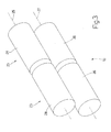
- Figure 3 shows a view in perspective of a traction roller unit of the Figure 1 machine;
- Figure 4 shows a sectioned side view of part of the Figure 3 traction roller unit;
- Figure 5 shows a sectioned plan view of part of the Figure 3 traction roller unit.
- Number 1 in Figure 1 indicates as a whole a dual cigarette filter manufacturing machine. Machine 1 comprises two forming
beams continuous filter rods beam material feed line lines conveyor line 5, which forms part of machine 1 and extends between an input station 6 offeed lines store 7 containing twobales - As shown in Figures 1 and 2, respective circular-
section wicks bales conveyor line 5 by traction imparted towicks traction roller unit 10a located at input station 6. -
Conveyor line 5 comprises aguide device 11 for guidingwicks bales suction device 12 located at input station 6, immediately upstream fromtraction roller unit 10a, and which widens circular-section wicks 9a, 9b transversely into respective flat-section strips traction roller unit 10a. - Downstream from
traction roller unit 10a, the twostrips respective feed lines horizontal direction 14, through apressing unit 15 comprising twotraction roller units unit 10a. Next, the twostrips respective feed lines direction 14, through aninflation device 16, which blows air intostrips strips processing unit 17, where chemical substances (typically, triacetin) are added tostrips strips respective feed lines direction 14, through atraction roller unit 10d similar tounits feed lines - Feed
lines beams unit 18 located immediately downstream fromtraction roller unit 10d, and which receivesstrips feed lines strips beams beam strip gumming station 20, and which is then wound transversely about the rope of filtering material to form acontinuous filter rod - At the output of forming
beams control station 21 checks the density offilter rods cutting head 22cuts rods -
Traction roller units feed lines traction roller units reference number 10. - As shown in Figure 3, each
traction roller unit 10 comprises, for each feed line 4, atraction device 23 comprising twoparallel rollers traction device 23 comprises adrive roller 24 rotated about an axis ofrotation 25 by a respective motor independent of the motor of theother drive roller 24 of the sametraction roller unit 10. Eachtraction device 23 also comprises a drivenroller 26, which is mounted idly to rotate freely about an axis ofrotation 27 parallel to axis ofrotation 25, and is tangent to and cooperates withdrive roller 24. - Each
traction device 23 comprises an adjusting device 28 (shown in Figures 4 and 5), which adjusts the distance between the tworollers traction device 23 independently of the distance between the tworollers other traction device 23. More specifically, in eachtraction device 23, the axis ofrotation 25 ofdrive roller 24 is fixed, whereas the axis ofrotation 27 of drivenroller 26 is movable parallel to itself, under the control ofrelative adjusting device 28, to and from axis ofrotation 25 to adjust the distance between the tworollers - As shown in Figures 4 and 5, each adjusting
device 28 comprises a fixed central supportingbody 29 supporting amovable frame 30, which houses drivenroller 26 in rotary manner with the interposition of a number ofbearings 31. In each adjustingdevice 28, alever 32 supportsmovable frame 30, and is hinged to supportingbody 29 to rotate about an adjustingaxis 33 crosswise to axis ofrotation 27. More specifically,lever 32 is in the form of a right-angle triangle, and adjustingaxis 33 extends through the right-angle of the right-angle triangle, so thatlever 32 is hinged centrally to supportingbody 29 to rotate about adjustingaxis 33, and has a first end connected to anactuator 34, and a second end, opposite the first end, connected tomovable frame 30. - In each adjusting
device 28,actuator 34 is connected to lever 32 to control the angular position oflever 32 about adjustingaxis 33, and comprises apush rod 35 resting againstlever 32, at a point of contact not aligned with adjustingaxis 33, to push and rotatelever 32 about adjustingaxis 33.Lever 32 preferably comprises acontact wheel 36 mounted to rotate idly onlever 32 and establish contact withpush rod 35. In other words,lever 32 is rotated about adjustingaxis 33 by axial displacement ofpush rod 35. - In a preferred embodiment, adjusting
axis 33 is horizontal, andlever 32 is rotated about adjustingaxis 33 in one direction by the weight of drivenroller 26, and in the opposite direction bypush rod 35 ofactuator 34. Sincelever 32 is maintained contactingpush rod 35 by the weight of drivenroller 26,push rod 35 need therefore simply rest against, as opposed to being secured to, lever 32. - In a preferred embodiment, each
actuator 34 is pneumatic, and comprises achamber 37 formed in supportingbody 29; a pressure regulator 38 (shown schematically in Figure 4) to regulate the pressure insidechamber 37; and apiston 39 sliding insidechamber 37 and connected mechanically to pushrod 35. Adjusting the pressure insidechamber 37 obviously adjusts compression of the filtering material by the two cooperatingrollers rollers chamber 37, is adjusted as a function of the format of the filters being produced, to ensure the best end quality at all times and minimize jamming. - It should be pointed out that, in each
traction roller unit 10, the two adjustingdevices 28 are located specularly with respect to a plane of symmetry perpendicular to the axes ofrotation 27 of the two drivenrollers 26, so that the twochambers 37 of the twopneumatic actuators 34 are located side by side, and thepneumatic actuators 34 therefore concentrated in a precisely defined region between the two drivenrollers 26 oftraction roller unit 10. - Each
adjusting device 28 comprises aposition sensor 40 for determining the distance between the tworollers position sensor 40 determines the distance between the tworollers lever 32 about adjustingaxis 33, e.g. by determining the axial position ofpush rod 35. More specifically,position sensor 40 comprises areader 41 carried in a fixed position by supportingbody 29; and ameasuring rod 42 carried bypush rod 35 and connected toreader 41 to enableposition sensor 40 to read the axial position ofpush rod 35. Preferably,reader 41 is a proximity measuring device, and measuringrod 42 is trapezoidal in shape, with a sloping surface located atreader 41. - A control unit 43 (shown schematically in Figure 4) is connected to
position sensors 40 to diagnose jamming of atraction device 23, in the event the distance between the relative tworollers position sensor 40 is memorized in a memory ofcontrol unit 43, and, during operation, the current value fromposition sensor 40 is compared continually with the initial value, and jamming is diagnosed in the event the current value increases excessively and/or tends to increase excessively with respect to the current value. In the event ajammed traction device 23 is diagnosed, thecorresponding adjusting device 28 is activated immediately to increase the distance between the tworollers traction device 23 to maximum as fast as possible. More specifically, to increase the distance between the tworollers traction device 23 as fast as possible, the pressure inchamber 37 ofpneumatic actuator 34 is simply cut off completely, so that the weight of drivenroller 26 is sufficient to rapidly distance drivenroller 26 fromdrive roller 24. - In a preferred embodiment, each
movable frame 30 supports drivenroller 26 in rotary manner about a self-adaptingaxis 44 parallel to adjustingaxis 33, and rotation ofmovable frame 30 about self-adaptingaxis 44 is limited in both directions by stops defined by fixed edges. Rotation ofmovable frame 30 about self-adaptingaxis 44 is limited to a few degrees, since the purpose of such rotation is simply to allow the position of drivenroller 26 to adapt automatically to a certain extent with respect to driveroller 24, to compensate for any manufacturing tolerances and/or irregularities in the material being worked. - In a preferred embodiment,
movable frame 30 comprises acylindrical pin 45 coaxial with self-adaptingaxis 44 and fixed rigidly throughlever 32.Movable frame 30 also comprises twobushes 46, which support drivenroller 26, and are fitted in rotary manner, by means ofpin 45, to the opposite ends ofpin 45. More specifically, eachbush 46 is fitted topin 45 with the interposition of arespective bearing 47. - It is important to note that the two
adjusting devices 28 oftraction roller unit 10 comprise a common fixed central supportingbody 29 supporting both drivenrollers 26. In the embodiment shown in the accompanying drawings, fixed central supportingbody 29 is fitted to and projects from a frame of machine 1, and is supported solely at the point at which it is joined to the frame. In an alternative embodiment not shown, fixed central supportingbody 29 is supported at the point at which it is joined to the frame, as well as at an intermediate portion of fixed central supportingbody 29 by means of a supporting member fixed to the frame. -
Traction roller units 10 have numerous advantages, by being cheap and easy to produce, while at the same time feeding the filtering material in the best possible manner along each production line. Moreover, any temporary differences along one production line (typically, localized nonhomogeneous nature of the filtering material) have absolutely no effect on the other production line. As such, dual machine 1 as described provides for producing filters of high quality comparable in all respects to that of filters produced on a single machine (i.e. featuring only one production line).
Claims (53)
- A cigarette filter manufacturing machine (1) comprising:at least two production lines; andat least one traction roller unit (10), which is located along the two production lines, and, for each production line, comprises a traction device (23) having two parallel rollers (24, 26) cooperating with each other and located a given adjustable distance apart;the machine (1) being characterized in that each traction device (23) comprises an adjusting device (28) for adjusting the distance between the two rollers (24, 26) of the traction device (23) independently of the distance between the two rollers (24, 26) of the other traction device (23).
- A machine (1) as claimed in Claim 1, wherein each traction device (23) comprises a first roller (24) rotating about a fixed first axis of rotation (25); and a second roller (26) rotating about a second axis of rotation (27) movable, parallel to itself and under the control of the relative adjusting device (28), to and from the first axis of rotation (25) to adjust the distance between the two rollers (24, 26).
- A machine (1) as claimed in Claim 2, wherein the first roller (24) is a powered drive roller, and the second roller (26) is an idle driven roller.
- A machine (1) as claimed in Claim 2 or 3, wherein each adjusting device (28) comprises a fixed central supporting body (29); a movable frame (30) housing the second roller (26) in rotary manner with the interposition of a number of first bearings (31); a lever (32) supporting the movable frame (30) and hinged to the supporting body (29) to rotate about a third adjusting axis (33) crosswise to the second axis of rotation (27); and an actuator (34) connected to the lever (32) to control the angular position of the lever (32) about the third adjusting axis (33).
- A machine (1) as claimed in Claim 4, wherein the lever (32) is in the form of a right-angle triangle; and the third adjusting axis (33) extends through the right-angle of the lever (32).
- A machine (1) as claimed in Claim 4 or 5, wherein the lever (32) is hinged centrally to the supporting body (29), and has a first end connected to the actuator (34), and a second end, opposite the first end, connected to the movable frame (30).
- A machine (1) as claimed in Claim 4, 5 or 6, wherein the actuator (34) comprises a push rod (35), which rests against the lever (32), at a point of contact not aligned with the third adjusting axis (33), and pushes the lever (32) to rotate the lever (32) about the third adjusting axis (33).
- A machine (1) as claimed in Claim 7, wherein the third adjusting axis (33) is horizontal, and the lever (32) is rotated about the third adjusting axis (33) in one direction by the weight of the second roller (26), and in the opposite direction by the push rod (35) of the actuator (34).
- A machine (1) as claimed in Claim 7 or 8, wherein the actuator (34) is pneumatic, and comprises a chamber (37) formed inside the supporting body (29); a pressure regulator (38) for regulating the pressure inside the chamber (37); and a piston (39) sliding inside the chamber (37) and connected mechanically to the push rod (35).
- A machine (1) as claimed in Claim 9, wherein the two adjusting devices (28) are located specularly with respect to a plane of symmetry perpendicular to the second axes of rotation (27), so that the two chambers (37) of the two pneumatic actuators (34) are side by side.
- A machine (1) as claimed in Claim 9 or 10, wherein the pressure regulator (38) regulates the pressure inside the chamber (37) as a function of the format of the filters for manufacture.
- A machine (1) as claimed in one of Claims 7 to 11, wherein each adjusting device (28) comprises a position sensor (40), which determines the distance between the two rollers (24, 26) by determining the position of the push rod (35); and the position sensor (40) comprises a reader (41) carried in a fixed position by the central supporting body (29), and a measuring rod (42) carried by the push rod (35) and connected to the reader (41) to enable the position sensor (40) to read the axial position of the push rod (35).
- A machine (1) as claimed in Claim 12, wherein the reader (41) is a proximity measuring device, and the measuring rod (42) is trapezoidal in shape, with a sloping surface located at the reader (41).
- A machine (1) as claimed in one of Claims 4 to 13, wherein each adjusting device (28) comprises a position sensor (40) which determines the distance between the two rollers (24, 26).
- A machine (1) as claimed in Claim 14, wherein the position sensor (40) determines the distance between the two rollers (24, 26) by determining the angular position of the lever (32) about the third adjusting axis (33).
- A machine (1) as claimed in Claim 14, wherein the position sensor (40) determines the distance between the two rollers (24, 26) by determining the position of a push rod (35) of the actuator (34), which acts on the lever.
- A machine (1) as claimed in Claim 14, 15 or 16, wherein a control unit (43) is connected to each position sensor (40) to diagnose jamming of a traction device (23) in the event the distance between the relative two rollers (24, 26) increases and/or tends to increase excessively.
- A machine (1) as claimed in Claim 17, wherein, at start-up, the initial value from a position sensor (40) is memorized, and, during operation, the current value from the position sensor (40) is compared continually with the initial value, and jamming is diagnosed in the event the current value increases excessively and/or tends to increase excessively with respect to the initial value.
- A machine (1) as claimed in Claim 17 or 18, wherein, when jamming of a traction device (23) is diagnosed, the corresponding adjusting device (28) is activated immediately to increase the distance between the two rollers (24, 26) of the traction device (23) to maximum as fast as possible.
- A machine (1) as claimed in one of Claims 4 to 19, wherein the movable frame (30) supports the second roller (26) in rotary manner about a fourth self-adapting axis (44) parallel to the third adjusting axis (33).
- A machine (1) as claimed in Claim 20, wherein rotation of the movable frame (30) about the fourth self-adapting axis (44) is limited in both directions by stops defined by fixed edges.
- A machine (1) as claimed in Claim 20 or 21, wherein the movable frame (30) comprises a cylindrical pin (45), which is coaxial with the fourth self-adapting axis (44), is fitted through the lever (32), and is fixed rigidly to the lever (32); and two bushes (46), which support the second roller (26), and are fitted in rotary manner, by means of the pin (45), to opposite ends of the pin (45).
- A machine (1) as claimed in Claim 22, wherein each of the two bushes (46) is fitted to the pin (45) with the interposition of a respective second bearing (47) .
- A machine (1) as claimed in one of Claims 1 to 23, wherein each traction device (23) comprises a first roller (24) rotating about a fixed first axis of rotation (25); and a second roller (26) rotating about a second axis of rotation (27) movable, parallel to itself and under the control of the relative adjusting device (28), to and from the first axis of rotation (25) to adjust the distance between the two rollers (24, 26); and the two adjusting devices (28) comprise a common fixed central supporting body (29) supporting both the second rollers (26).
- A machine (1) as claimed in Claim 24, wherein the fixed central supporting body (29) is fitted to and projects from a frame of the machine (1), and is supported solely at the point at which it is joined to the frame.
- A machine (1) as claimed in Claim 24, wherein the fixed central supporting body (29) is fitted to and projects from a frame of the machine (1), and is supported at the point at which it is joined to the frame, as well as at an intermediate portion of the fixed central supporting body (29).
- A machine (1) as claimed in Claim 26, wherein an intermediate portion of the fixed central supporting body (29) is supported by a supporting member fixed to the frame.
- A machine (1) as claimed in one of Claims 1 to 27, wherein each production line comprises a feed line (4) for a continuous strip (13) of filtering material; a forming beam (2) for forming a continuous filter rod (3); and a stabilizing unit (18) located between the feed line (4) and the forming beam (2); and the feed line (4) comprises a pressing unit (15) defined by two traction roller units (10b, 10c), each of which comprises two traction devices (23) and two respective adjusting devices (28).
- A machine (1) as claimed in Claim 28, wherein each feed line (4) also comprises an inflation device (16) downstream from the pressing unit (15); a processing unit (17) downstream from the inflation device (16); and a further traction roller unit (10d), which defines an output portion of the feed line (4), and comprises two traction devices (23) and two respective adjusting devices (28).
- A cigarette filter manufacturing machine (1) comprising:at least two production lines; andat least one traction roller unit (10), which is located along the two production lines, and, for each production line, comprises a traction device (23) having two parallel rollers (24, 26) cooperating with each other and located a given adjustable distance apart;each traction device (23) comprises an adjusting device (28) for adjusting the distance between the two rollers (24, 26) of the traction device (23), and which comprises a pneumatic actuator (34) having a chamber (37) and a piston (39) sliding inside the chamber (37);the machine (1) being characterized in that the two adjusting devices (28) are located specularly with respect to a plane of symmetry perpendicular to the axes of rotation (25, 27) of the rollers (24, 26), so that the two chambers (37) of the two pneumatic actuators (34) are side by side.
- A cigarette filter manufacturing machine (1) comprising:at least one production line; andat least one traction roller unit (10), which is located along the production line, and comprises a traction device (23) having two parallel rollers (24, 26) cooperating with each other and located a given adjustable distance apart, and an adjusting device (28) for adjusting the distance between the two rollers (24, 26) of the traction device (23);the traction device (23) comprises a first roller (24) rotating about a fixed first axis of rotation (25); and a second roller (26) rotating about a second axis of rotation (27) movable, parallel to itself and under the control of the adjusting device (28), to and from the first axis of rotation (25) to adjust the distance between the two rollers (24, 26);and the machine (1) is characterized in that the adjusting device (28) comprises a fixed central supporting body (29); a movable frame (30) housing the second roller (26) in rotary manner with the interposition of a number of first bearings (31); a lever (32) supporting the movable frame (30) and hinged to the fixed central supporting body (29) to rotate about a third adjusting axis (33) crosswise to the second axis of rotation (27); and an actuator (34) connected to the lever (32) to control the angular position of the lever (32) about the third adjusting axis (33).
- A machine (1) as claimed in Claim 31, wherein the first roller (24) is a powered drive roller, and the second roller (26) is an idle driven roller.
- A machine (1) as claimed in Claim 31 or 32, wherein the lever (32) is in the form of a right-angle triangle; and the third adjusting axis (33) extends through the right-angle of the lever (32).
- A machine (1) as claimed in Claim 31, 32 or 33, wherein the lever (32) is hinged centrally to the central supporting body (29), and has a first end connected to the actuator (34), and a second end, opposite the first end, connected to the movable frame (30).
- A machine (1) as claimed in one of Claims 31 to 34, wherein the actuator (34) comprises a push rod (35), which rests against the lever (32), at a point of contact not aligned with the third adjusting axis (33), and pushes the lever (32) to rotate the lever (32) about the third adjusting axis (33).
- A machine (1) as claimed in Claim 35, wherein the third adjusting axis (33) is horizontal, and the lever (32) is rotated about the third adjusting axis (33) in one direction by the weight of the driven roller, and in the opposite direction by the push rod (35) of the actuator (34) .
- A machine (1) as claimed in Claim 36, wherein the actuator (34) is pneumatic, and comprises a chamber (37) formed inside the central supporting body (29); a pressure regulator (38) for regulating the pressure inside the chamber (37); and a piston (39) sliding inside the chamber (37) and connected mechanically to the push rod (35).
- A machine (1) as claimed in Claim 37, wherein the pressure regulator (38) regulates the pressure inside the chamber (37) as a function of the format of the filters for manufacture.
- A machine (1) as claimed in one of Claims 35 to 38, wherein the adjusting device (28) comprises a position sensor (40), which determines the distance between the two rollers (24, 26) by determining the position of the push rod (35); and the position sensor (40) comprises a reader (41) carried in a fixed position by the central supporting body (29), and a measuring rod (42) carried by the push rod (35) and connected to the reader (41) to enable the position sensor (40) to read the axial position of the push rod (35).
- A machine (1) as claimed in Claim 39, wherein the reader (41) is a proximity measuring device, and the measuring rod is trapezoidal in shape, with a sloping surface located at the reader (41).
- A machine (1) as claimed in one of Claims 31 to 40, wherein the adjusting device (28) comprises a position sensor (40) which determines the distance between the two rollers (24, 26).
- A machine (1) as claimed in Claim 41, wherein the position sensor (40) determines the distance between the two rollers (24, 26) by determining the angular position of the lever (32) about the third adjusting axis (33).
- A machine (1) as claimed in Claim 41, wherein the position sensor (40) determines the distance between the two rollers (24, 26) by determining the position of a push rod (35) of the actuator (34), which acts on the lever.
- A machine (1) as claimed in Claim 41, 42 or 43, wherein a control unit (43) is connected to each position sensor (40) to diagnose jamming of the traction device (23) in the event the distance between the two rollers (24, 26) increases and/or tends to increase excessively.
- A machine (1) as claimed in Claim 44, wherein, at start-up, the initial value from the position sensor (40) is memorized, and, during operation, the current value from the position sensor (40) is compared continually with the initial value, and jamming is diagnosed in the event the current value increases excessively and/or tends to increase excessively with respect to the initial value.
- A machine (1) as claimed in Claim 44 or 45, wherein, when jamming of a traction device (23) is diagnosed, the corresponding adjusting device (28) is activated immediately to increase the distance between the two rollers (24, 26) of the traction device (23) to maximum as fast as possible.
- A machine (1) as claimed in one of Claims 31 to 46, wherein the movable frame (30) supports the driven roller in rotary manner about a fourth self-adapting axis (44) parallel to the third adjusting axis (33).
- A machine (1) as claimed in Claim 47, wherein rotation of the movable frame (30) about the fourth self-adapting axis (44) is limited in both directions by stops defined by fixed edges.
- A machine (1) as claimed in Claim 47 or 48, wherein the movable frame (30) comprises a cylindrical pin (45), which is coaxial with the fourth self-adapting axis (44), is fitted through the lever (32), and is fixed rigidly to the lever (32); and two bushes (46), which support the driven roller (26), and are fitted in rotary manner, by means of the pin (45), to opposite ends of the pin (45).
- A machine (1) as claimed in Claim 49, wherein each of the two bushes (46) is fitted to the pin (45) with the interposition of a respective second bearing (47) .
- A cigarette filter manufacturing machine (1) comprising:at least one production line; andat least one traction roller unit (10), which is located along the production line, and comprises a traction device (23) having two parallel rollers (24, 26) cooperating with each other and located a given adjustable distance apart, and an adjusting device (28) for adjusting the distance between the two rollers (24, 26) of the traction device (23);the machine (1) is characterized in that the adjusting device (28) comprises a position sensor (40) for determining the distance between the two rollers (24, 26) of the traction device (23); and a control unit (43) connected to the position sensor (40) to diagnose jamming in the event the distance between the two rollers (24, 26) of the traction device (23) increases and/or tends to increase excessively.
- A machine (1) as claimed in Claim 51, wherein, at start-up, the initial value from the position sensor (40) is memorized, and, during operation, the current value from the position sensor (40) is compared continually with the initial value, and jamming is diagnosed in the event the current value increases excessively and/or tends to increase excessively with respect to the initial value.
- A machine (1) as claimed in Claim 51 or 52, wherein, when jamming of the traction device (23) is diagnosed, the adjusting device (28) is activated immediately to increase the distance between the two rollers (24, 26) of the traction device (23) to maximum as fast as possible.
Priority Applications (1)
| Application Number | Priority Date | Filing Date | Title |
|---|---|---|---|
| DE200720019146 DE202007019146U1 (en) | 2006-03-08 | 2007-03-07 | Cigarette filter manufacturing machine |
Applications Claiming Priority (1)
| Application Number | Priority Date | Filing Date | Title |
|---|---|---|---|
| ITBO20060165 ITBO20060165A1 (en) | 2006-03-08 | 2006-03-08 | MACHINE FOR THE PRODUCTION OF CIGARETTE FILTERS. |
Publications (3)
| Publication Number | Publication Date |
|---|---|
| EP1832183A2 true EP1832183A2 (en) | 2007-09-12 |
| EP1832183A3 EP1832183A3 (en) | 2007-09-26 |
| EP1832183B1 EP1832183B1 (en) | 2010-12-22 |
Family
ID=38080954
Family Applications (1)
| Application Number | Title | Priority Date | Filing Date |
|---|---|---|---|
| EP20070103723 Active EP1832183B1 (en) | 2006-03-08 | 2007-03-07 | Cigarette filter manufacturing machine |
Country Status (4)
| Country | Link |
|---|---|
| EP (1) | EP1832183B1 (en) |
| CN (1) | CN101120817B (en) |
| DE (2) | DE602007011337D1 (en) |
| IT (1) | ITBO20060165A1 (en) |
Cited By (1)
| Publication number | Priority date | Publication date | Assignee | Title |
|---|---|---|---|---|
| ITBO20090551A1 (en) * | 2009-08-18 | 2011-02-19 | Gd Spa | METHOD AND MACHINE FOR THE CONTEMPORARY PRODUCTION OF AT LEAST TWO FILTER BUGS FOR CIGARETTES. |
Citations (6)
| Publication number | Priority date | Publication date | Assignee | Title |
|---|---|---|---|---|
| EP0237288A2 (en) * | 1986-03-07 | 1987-09-16 | Celanese Corporation | Diagnostic and control system for cigarette filter rod making machine |
| GB2265298A (en) * | 1992-03-26 | 1993-09-29 | Koerber Ag | Method of and machine for making filters for rod-shaped smokers' products |
| DE4308093A1 (en) * | 1992-03-26 | 1993-09-30 | Hauni Werke Koerber & Co Kg | Method for making smoking article filter |
| EP0629356A1 (en) * | 1993-06-18 | 1994-12-21 | Rhone-Poulenc Rhodia Aktiengesellschaft | Process and apparatus for the production of fibre strands |
| WO2004000046A1 (en) * | 2002-06-20 | 2003-12-31 | International Tobacco Machinery B.V. | Roll pair for stretching strips of filter material |
| WO2005058079A1 (en) * | 2003-11-25 | 2005-06-30 | Hauni Maschinenbau Aktiengesellschaft | Device for processing filter tow material, and device for the production of filters |
-
2006
- 2006-03-08 IT ITBO20060165 patent/ITBO20060165A1/en unknown
-
2007
- 2007-03-07 DE DE200760011337 patent/DE602007011337D1/en active Active
- 2007-03-07 EP EP20070103723 patent/EP1832183B1/en active Active
- 2007-03-07 DE DE200720019146 patent/DE202007019146U1/en not_active Expired - Lifetime
- 2007-03-08 CN CN 200710087764 patent/CN101120817B/en not_active Expired - Fee Related
Patent Citations (6)
| Publication number | Priority date | Publication date | Assignee | Title |
|---|---|---|---|---|
| EP0237288A2 (en) * | 1986-03-07 | 1987-09-16 | Celanese Corporation | Diagnostic and control system for cigarette filter rod making machine |
| GB2265298A (en) * | 1992-03-26 | 1993-09-29 | Koerber Ag | Method of and machine for making filters for rod-shaped smokers' products |
| DE4308093A1 (en) * | 1992-03-26 | 1993-09-30 | Hauni Werke Koerber & Co Kg | Method for making smoking article filter |
| EP0629356A1 (en) * | 1993-06-18 | 1994-12-21 | Rhone-Poulenc Rhodia Aktiengesellschaft | Process and apparatus for the production of fibre strands |
| WO2004000046A1 (en) * | 2002-06-20 | 2003-12-31 | International Tobacco Machinery B.V. | Roll pair for stretching strips of filter material |
| WO2005058079A1 (en) * | 2003-11-25 | 2005-06-30 | Hauni Maschinenbau Aktiengesellschaft | Device for processing filter tow material, and device for the production of filters |
Cited By (1)
| Publication number | Priority date | Publication date | Assignee | Title |
|---|---|---|---|---|
| ITBO20090551A1 (en) * | 2009-08-18 | 2011-02-19 | Gd Spa | METHOD AND MACHINE FOR THE CONTEMPORARY PRODUCTION OF AT LEAST TWO FILTER BUGS FOR CIGARETTES. |
Also Published As
| Publication number | Publication date |
|---|---|
| DE202007019146U1 (en) | 2010-12-16 |
| CN101120817B (en) | 2011-11-30 |
| ITBO20060165A1 (en) | 2007-09-09 |
| CN101120817A (en) | 2008-02-13 |
| DE602007011337D1 (en) | 2011-02-03 |
| EP1832183A3 (en) | 2007-09-26 |
| EP1832183B1 (en) | 2010-12-22 |
Similar Documents
| Publication | Publication Date | Title |
|---|---|---|
| US7322175B2 (en) | Crop conditioning roller flute shape | |
| CN104023567B (en) | Equipment for the continuous web of supply curling sheet material and method | |
| US20080115641A1 (en) | Device for longitudinally cutting a continuously conveyed width of material in order to form a strip with a variable longitudinal profile | |
| CN107599033B (en) | Device and method for cutting a strip of material web of the tobacco processing industry | |
| EP1480790B1 (en) | Soft goods slitter and feed system for quilting | |
| JPS6186351A (en) | Raw fabric reel changeover method for packaging machine and device thereof | |
| KR102617548B1 (en) | Method and apparatus for manufacturing crimped sheet material | |
| KR101129051B1 (en) | Cutting assembly and cutting machine for cutting uncut film of adhesive tape and method for manufacturing adhesive tape with cut area by using the same | |
| CN105398863A (en) | Label sheet slitting apparatus | |
| PL206657B1 (en) | Web- or belt-type material handling apparatus and method of controlling the tensile stress in that material | |
| EP1832183B1 (en) | Cigarette filter manufacturing machine | |
| EP2422943A1 (en) | Tearing device of a continuous ribbon of paper material to be supplied on rewinding machines, rewinding machine for the formation of logs of paper equipped with such a device and tearing method of a continuous ribbon of paper material on rewinding machines | |
| CN113978043A (en) | Wet piece of cloth automation line | |
| US7302781B2 (en) | Bander apparatus and method of using same | |
| US10668685B2 (en) | Folding arrangement, folding machine and method for folding | |
| JP5159182B2 (en) | Sheet cutting device | |
| EP2090535B1 (en) | Device for cross-cutting web materials | |
| DE10336757B4 (en) | Taschenfalzverfahren | |
| GB2134432A (en) | Cork paper cutter | |
| US4946085A (en) | Apparatus for producing paper with decorative edges | |
| CN202594484U (en) | Absorber processing device | |
| JP2019509725A (en) | Apparatus and method for producing a semi-finished product intended to form part of a smoker product | |
| CN206552895U (en) | Inclined flattening die cutting machine rolling-up mechanism | |
| US20020139891A1 (en) | Web storage device for a packaging machine | |
| EP1799553B1 (en) | Bander apparatus and method of using same |
Legal Events
| Date | Code | Title | Description |
|---|---|---|---|
| PUAI | Public reference made under article 153(3) epc to a published international application that has entered the european phase |
Free format text: ORIGINAL CODE: 0009012 |
|
| PUAL | Search report despatched |
Free format text: ORIGINAL CODE: 0009013 |
|
| AK | Designated contracting states |
Kind code of ref document: A2 Designated state(s): AT BE BG CH CY CZ DE DK EE ES FI FR GB GR HU IE IS IT LI LT LU LV MC MT NL PL PT RO SE SI SK TR |
|
| AX | Request for extension of the european patent |
Extension state: AL BA HR MK YU |
|
| AK | Designated contracting states |
Kind code of ref document: A3 Designated state(s): AT BE BG CH CY CZ DE DK EE ES FI FR GB GR HU IE IS IT LI LT LU LV MC MT NL PL PT RO SE SI SK TR |
|
| AX | Request for extension of the european patent |
Extension state: AL BA HR MK YU |
|
| 17P | Request for examination filed |
Effective date: 20080325 |
|
| 17Q | First examination report despatched |
Effective date: 20080428 |
|
| AKX | Designation fees paid |
Designated state(s): CH DE GB LI |
|
| TPAC | Observations filed by third parties |
Free format text: ORIGINAL CODE: EPIDOSNTIPA |
|
| GRAP | Despatch of communication of intention to grant a patent |
Free format text: ORIGINAL CODE: EPIDOSNIGR1 |
|
| GRAS | Grant fee paid |
Free format text: ORIGINAL CODE: EPIDOSNIGR3 |
|
| GRAA | (expected) grant |
Free format text: ORIGINAL CODE: 0009210 |
|
| AK | Designated contracting states |
Kind code of ref document: B1 Designated state(s): CH DE GB LI |
|
| REG | Reference to a national code |
Ref country code: GB Ref legal event code: FG4D |
|
| REG | Reference to a national code |
Ref country code: CH Ref legal event code: EP |
|
| REF | Corresponds to: |
Ref document number: 602007011337 Country of ref document: DE Date of ref document: 20110203 Kind code of ref document: P |
|
| REG | Reference to a national code |
Ref country code: DE Ref legal event code: R096 Ref document number: 602007011337 Country of ref document: DE Effective date: 20110203 |
|
| PLBE | No opposition filed within time limit |
Free format text: ORIGINAL CODE: 0009261 |
|
| STAA | Information on the status of an ep patent application or granted ep patent |
Free format text: STATUS: NO OPPOSITION FILED WITHIN TIME LIMIT |
|
| REG | Reference to a national code |
Ref country code: CH Ref legal event code: PL |
|
| 26N | No opposition filed |
Effective date: 20110923 |
|
| REG | Reference to a national code |
Ref country code: DE Ref legal event code: R097 Ref document number: 602007011337 Country of ref document: DE Effective date: 20110923 |
|
| PG25 | Lapsed in a contracting state [announced via postgrant information from national office to epo] |
Ref country code: LI Free format text: LAPSE BECAUSE OF NON-PAYMENT OF DUE FEES Effective date: 20110331 Ref country code: CH Free format text: LAPSE BECAUSE OF NON-PAYMENT OF DUE FEES Effective date: 20110331 |
|
| PGFP | Annual fee paid to national office [announced via postgrant information from national office to epo] |
Ref country code: GB Payment date: 20160329 Year of fee payment: 10 |
|
| GBPC | Gb: european patent ceased through non-payment of renewal fee |
Effective date: 20170307 |
|
| PG25 | Lapsed in a contracting state [announced via postgrant information from national office to epo] |
Ref country code: GB Free format text: LAPSE BECAUSE OF NON-PAYMENT OF DUE FEES Effective date: 20170307 |
|
| PGFP | Annual fee paid to national office [announced via postgrant information from national office to epo] |
Ref country code: DE Payment date: 20230329 Year of fee payment: 17 |