EP1832158A1 - Plant culturing device - Google Patents
Plant culturing device Download PDFInfo
- Publication number
- EP1832158A1 EP1832158A1 EP05822576A EP05822576A EP1832158A1 EP 1832158 A1 EP1832158 A1 EP 1832158A1 EP 05822576 A EP05822576 A EP 05822576A EP 05822576 A EP05822576 A EP 05822576A EP 1832158 A1 EP1832158 A1 EP 1832158A1
- Authority
- EP
- European Patent Office
- Prior art keywords
- culturing
- tank
- liquid
- vessel
- plant
- Prior art date
- Legal status (The legal status is an assumption and is not a legal conclusion. Google has not performed a legal analysis and makes no representation as to the accuracy of the status listed.)
- Granted
Links
Images




Classifications
-
- A—HUMAN NECESSITIES
- A01—AGRICULTURE; FORESTRY; ANIMAL HUSBANDRY; HUNTING; TRAPPING; FISHING
- A01G—HORTICULTURE; CULTIVATION OF VEGETABLES, FLOWERS, RICE, FRUIT, VINES, HOPS OR SEAWEED; FORESTRY; WATERING
- A01G27/00—Self-acting watering devices, e.g. for flower-pots
- A01G27/02—Self-acting watering devices, e.g. for flower-pots having a water reservoir, the main part thereof being located wholly around or directly beside the growth substrate
-
- A—HUMAN NECESSITIES
- A01—AGRICULTURE; FORESTRY; ANIMAL HUSBANDRY; HUNTING; TRAPPING; FISHING
- A01G—HORTICULTURE; CULTIVATION OF VEGETABLES, FLOWERS, RICE, FRUIT, VINES, HOPS OR SEAWEED; FORESTRY; WATERING
- A01G27/00—Self-acting watering devices, e.g. for flower-pots
- A01G27/005—Reservoirs connected to flower-pots through conduits
-
- A—HUMAN NECESSITIES
- A01—AGRICULTURE; FORESTRY; ANIMAL HUSBANDRY; HUNTING; TRAPPING; FISHING
- A01G—HORTICULTURE; CULTIVATION OF VEGETABLES, FLOWERS, RICE, FRUIT, VINES, HOPS OR SEAWEED; FORESTRY; WATERING
- A01G27/00—Self-acting watering devices, e.g. for flower-pots
-
- A—HUMAN NECESSITIES
- A01—AGRICULTURE; FORESTRY; ANIMAL HUSBANDRY; HUNTING; TRAPPING; FISHING
- A01G—HORTICULTURE; CULTIVATION OF VEGETABLES, FLOWERS, RICE, FRUIT, VINES, HOPS OR SEAWEED; FORESTRY; WATERING
- A01G9/00—Cultivation in receptacles, forcing-frames or greenhouses; Edging for beds, lawn or the like
- A01G9/02—Receptacles, e.g. flower-pots or boxes; Glasses for cultivating flowers
-
- A—HUMAN NECESSITIES
- A01—AGRICULTURE; FORESTRY; ANIMAL HUSBANDRY; HUNTING; TRAPPING; FISHING
- A01G—HORTICULTURE; CULTIVATION OF VEGETABLES, FLOWERS, RICE, FRUIT, VINES, HOPS OR SEAWEED; FORESTRY; WATERING
- A01G9/00—Cultivation in receptacles, forcing-frames or greenhouses; Edging for beds, lawn or the like
- A01G9/02—Receptacles, e.g. flower-pots or boxes; Glasses for cultivating flowers
- A01G9/022—Pots for vertical horticulture
- A01G9/023—Multi-tiered planters
Definitions
- the present invention relates to a plant culturing apparatus including a culturing vessel capable of culturing a plant therein, a tank capable of reserving a culturing liquid for the plant therein, a communication passage communicating between the vessel and the tank, and a pump incorporated in the communication passage, the pump being capable of feeding the liquid reserved in the tank to the plant culturing vessel.
- the plant culturing apparatus described above is capable of feeding the reserved liquid in the tank to the culturing vessel with an operation of the pump provided in the communication passage between the culturing vessel and the tank, so that a watering operation to the plant can be simple.
- the culturing vessel and the tank are provided separately of each other and connected via a tube forming the communication passage (see e.g. Patent Document 1).
- Patent Document 1 Japanese Patent Application "Kokai" No. 2004-24029
- the present invention has been made in view of the above-described state of the art and its object is to construct the apparatus convenient in the respects of both the installing space and movability of the culturing vessel.
- the plant culturing apparatus comprises: a culturing vessel capable of culturing a plant therein, a tank capable of reserving a culturing liquid for the plant therein, a communication passage communicating between the vessel and the tank, and a pump incorporated in the communication passage, the pump being capable of feeding the liquid reserved in the tank to the plant culturing vessel; wherein said tank includes a support portion capable of supporting the culturing vessel upwardly of the tank; said communication passage is disposed along said support portion; and said pump is provided integrally with said tank.
- the tank is provided with the support portion capable of supporting the culturing vessel upwardly of the tank.
- the communication passage for communicating the culturing vessel with the tank is disposed along the support portion and the pump capable of feeding the reserved liquid in the tank to the culturing vessel is provided integrally with the tank.
- the apparatus can be constructed so as to allow returning of any excess liquid from the culturing liquid fed to the culturing vessel back to the tank via the communication passage.
- any excess liquid from the culturing liquid fed to the culturing vessel can be returned to the tank via the communication passage.
- the feeding of the culturing liquid from the tank to the culturing vessel and the returning of the excess liquid from the culturing vessel to the tank are effected by using the same communication passage. Therefore, this is no need of providing separately a passage for returning the excess liquid to the tank, so that by returning the excess liquid to the tank, the root rot of the plant can be prevented and also the culturing liquid can be used efficiently.
- said pump is constructed as a tube pump which can be switched over between a condition for feeding the reserved liquid to the culturing vessel and a further condition for introducing into the tank, excess liquid from the culturing liquid fed to the culturing vessel and aerating air for bubbling in the reserved liquid.
- the pump capable of feeding the reserved liquid in the tank to the culturing vessel is constructed as a tube pump which can be formed compact and generate less vibration and noise in its driving condition, as compared with a vacuum pump or a compressor. Therefore, the apparatus can be readily installed in such place as a balcony, sun room, or a room of a private house, without damaging its environment.
- this tube pump can be switched over between a condition for feeding the reserved liquid to the culturing vessel and a further condition for introducing into the tank, excess liquid from the culturing liquid fed to the culturing vessel and aerating air for bubbling in the reserved liquid, then, by switching over this tube pump to the condition for introducing into the tank, excess liquid from the culturing liquid fed to the culturing vessel and aerating air for bubbling in the reserved liquid, the excess liquid can be positively returned to the tank for preventing root rot of the plant and the culturing liquid can be used efficiently, without having to provide separately an additional passage for returning the excess liquid to the tank.
- the aerating air can be introduced into the tank for supplying oxygen to the culturing liquid reserved in the tank, decay of the culturing liquid can be effectively avoided and culturing liquid rich in oxygen dissolved therein can be supplied to the culturing vessel.
- said tank can include a further culturing vessel other than said culturing vessel, so that the reserved liquid can be supplied naturally to said further culturing vessel.
- the tank includes a further culturing vessel other than said culturing vessel, so that the reserved liquid can be supplied naturally to said further culturing vessel. Then, in the further culturing vessel capable of naturally supplying the reserved liquid to the tank in addition to the culturing vessel supported upwardly of the tank, the plant can be easily cultured without effecting a watering operation in particular. Further, the vicinity of the tank can be decorated neatly with the plant cultured in the further culturing vessel.
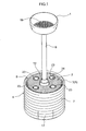
- Figs. 1 and 2 show a plant culturing apparatus according to the present invention.
- the apparatus includes upper and lower culturing vessels 1, 2 formed of resin and capable of culturing plants A therein, and a tank 4 formed of resin and capable of reserving culturing liquid 3 containing fertilizer components and antiseptic components dissolved in water for the plants A cultured in the respective culturing vessels 1, 2.
- this apparatus can be installed as a three-dimensional flowerbed.
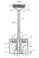
- the tank 4 includes a cylindrical inner peripheral wall 6 and an outer peripheral wall 7 disposed coaxially. Between the inner peripheral wall 6 and the outer peripheral wall 7, there is formed a continuous annular upward opening 8, in which the further culturing vessel other than the upper culturing vessel 1, namely, the lower culturing vessel 2 is provided.
- a hollow cylindrical support member 9 capable of supporting the upper culturing vessel 1 upwardly of the tank 4 is inserted coaxially inside the inner peripheral wall 6; a base plate 10 secured to the lower end of the support member 9 is fixed to a tank bottom plate 11; a truncated conical cap 12 is provided for closing a gap between the support member 9 and the inner peripheral wall 6.
- the upper culturing vessel 1 and the tank 4 are connected and communicated with each other via a flexible resin tube 13 forming a communication passage 26 therein; and at an intermediate portion of this tube 13, there is connected a pump P capable of feeding the reserved liquid (culturing liquid) 3 in the tank 4 to the upper culturing vessel 1, thus providing automatic watering to the upper culturing vessel 1.
- the pump P is an electric driven tube pump (“Peristapump” (registered trademark)) including a control unit 14 incorporating a control section capable of automatic switchover between a condition for feeding the culturing liquid 3 through the tube 13 to the upper culturing vessel 1 and a further condition for introducing through the tube 13 to the tank 4, excess liquid 3a accumulated at a lower portion of a catch basin 19 from the culturing liquid 3 fed to the upper culturing liquid 1 as well as aeration air for bubbling in the reserved liquid 3 and a panel switch 15 for allowing setting, in the control unit 14, a driving interval of the tube pump P and various control modes such as suctioning/discharging directions, etc.
- the excess liquid 3a from the culturing liquid 3 fed to the upper culturing vessel 1 can be returned to the tank 4 via the tube 13.
- the tube pump P, the control unit 14 and the panel switch 15 are fixed to the base plate 10 and are accommodated in an accommodating space 16 formed between the base plate 10 and a partially upward convex portion of the tank bottom plate 11, so that the pump P, the unit 14 and the switch 15 are provided integrally and together downwardly of the tank 4. Further, a lid member 17 capable of opening/closing the accommodating space 16 is detachably provided to conform to the outer peripheral shape of the tank 4.
- an unillustrated external power source is provided as a power source for the tube pump P, the control unit 14, etc.
- an internal power source such as a battery accommodated in the accommodating space 16 can be employed instead.
- the upper culturing vessel 1 is provided in the form of an upwardly oriented approximately circular bowl, with the catch basin 19 provided therein so as to be capable of accommodating, upwardly of the catch basin 19, a culture medium 18 for culturing the plant A.
- a culture medium 18 for culturing the plant A examples include such commonly employed natural media as compost, leaf mold, peat moss, as well as artificial media such as vermiculite, pearlite, rock wool, hydro ball, sponge, etc. which media are preformed for easy replacement of the plant A.
- the support member 9 is fixed and supported upwardly of the tank 4, with a connector portion 20 projecting inside the support member 9 for allowing connection of the tube communicated with the lower vessel side of the catch basin 19.
- an upstream portion 21 thereof connecting between the tube pump P and the tank 4 extends through a gap formed between the support member 9 and the inner peripheral wall 6 and extends through a side hole defined in the inner peripheral wall 6 into the reserved liquid 3, with its open end being submerged in the reserved liquid 3.
- a downstream portion 22 thereof connecting between the tube pump P and the upper culturing vessel 1 extends along and inside the support member 9 to be connected to the connector portion 20.
- a bypass passage 30 connecting between the upstream portion 21 and the downstream portion 22 of the tube 13, together with a valve 31 incorporated therein.
- the pump P When the reserved liquid 3 in the tank 4 is to be supplied to the upper culturing vessel 1, the pump P will be driven and the valve 31 will be closed. In this case, a normal feeding operation will be effected. Whereas, when the excess liquid 3a from the culturing liquid 3 fed to the upper culturing vessel 1 is to be returned to the tank 4, the pump P will be stopped and the valve 31 will be opened. In this case, the excess liquid 3a will flow under the gravity effect from the downstream portion 22 of the tube 13 through the bypass passage 30 to the upstream portion 21 of the tube 13.
- a narrow tube 40 which extends from the upper culturing vessel 1 through the inside of the support member 9 and through the inner peripheral wall 6 to be communicated with the tank 4.
- this construction can eliminate the necessity of watering operation to the lower culturing vessel 2 and also can maintain balance between the reserved liquid 3 in the tank 4 and the excess liquid 3a in the upper culturing vessel 1, only with occasional driving of the pump P. Further, an inexpensive pump can be employed since there is no need for changing the suctioning/ discharging directions of the pump P.
- a normal feeding operation will be effected by driving the pump P, with opening the valves 51, 52 and closing the valves 53, 54.
- the driving of the pump P will be maintained, with closing this time the valves 51, 52 and opening the valves 53, 54.
- the suctioning side of the pump P is connected to the downstream portion 22 and the discharging side thereof is connected to the upstream portion 21, respectively, so that the flowing directions of the reserved liquid 3 and the excess liquid 3a are reversed.
- the lower culturing vessel 2 is formed annular in its plan view and made of foamed polystyrene. And, this vessel 2 is fitted coaxially in the reserving section 5 through its upward opening 8.
- the vessel 2 defines a plurality of circular accommodating holes 24 along the peripheral direction, each hole 24 allowing insertion and removal of a preformed culture medium 23 having a cylindrical shape equipped with a bottom and formed of a porous material such as a sponge for allowing passage of air and the culturing liquid 3.
- a through hole 25 for allowing natural feeding of the reserved liquid 3 in the reserving section 5 to the inside of the preformed culture medium 23 through this through hole 25.
- the vessel 2 is constructed to allow the floating water culturing as the vessel 2 is afloat in the reserved liquid 3 together with the plants A planted within the respective preformed culture media 23.
- this vessel 2 can act also as a water gauge for allowing one to know the liquid level of the reserved liquid 3 from the level of this lower culturing vessel 2.
- the culturing vessels constituting the plant culturing apparatus are provided in multiple stages.
- Fig. 7 is a perspective view of the multiple stages of the plant culturing vessels and
- Fig. 8 is a front view of the multiple stages of the plant culturing vessels.
- a three-stage type plant culturing apparatus including plant culturing vessels 61, 62, 63.
- the number of stages can vary as desired.
- the lowermost stage culturing vessel 61 accommodates the pump P (not shown), so that the reserved liquid in this culturing vessel 61 is transported by the pump P to the uppermost stage culturing vessel 63. Excess liquid from the reserved liquid transported to the culturing vessel 63 will eventually overflow to be supplied to the lower culturing vessel 62 downwardly thereof. Next, excess liquid from this culturing liquid supplied to the culturing vessel 62 will overflow to be supplied to the lowermost culturing vessel 61 downwardly thereof. And, this culturing liquid supplied to the culturing vessel 61 will be transported again by the pump P to the uppermost culturing vessel 63. In this way, the reserved liquid will be circulated to/from the respective culturing vessels 61, 62, 63.
- each culturing vessel 61, 62, 63 there can be provided a medium fixing means 64, 65, 66.
- a plant culturing medium 71, 72, 73 can be fitted in a recess formed in the medium fixing means 64, 65, 66.
- the medium 71, 72, 73 is formed of an elastic member such as a sponge, the medium will be elastically clamped within the medium fixing means 64, 65, 66. As a result, there will occur no sweeping away or displacement of the medium by e.g. the reserved liquid.
- the lowermost stage is constructed as the float watering type construction like the one shown in Fig. 3, it becomes possible for one to learn the liquid level of the reserved liquid in the culturing vessel 61.
- the lowermost culturing vessel 61 has an inwardly projecting dome-shaped bottom portion 67 to secure sufficient rigidity. Therefore, the posture of the plant culturing apparatus can be stable and will not topple easily.
- the plant culturing apparatus according to the present invention requires only small space for its installment and can be readily handled since the culturing vessel and the tank can be moved together. Therefore, the inventive plant culturing apparatus can be used not only for industrial purpose, but also for domestic purpose, being applicable for a great variety of usages.
Landscapes
- Life Sciences & Earth Sciences (AREA)
- Environmental Sciences (AREA)
- Engineering & Computer Science (AREA)
- Water Supply & Treatment (AREA)
- Hydroponics (AREA)
- Cultivation Receptacles Or Flower-Pots, Or Pots For Seedlings (AREA)
- Apparatus Associated With Microorganisms And Enzymes (AREA)
Abstract
Description
- The present invention relates to a plant culturing apparatus including a culturing vessel capable of culturing a plant therein, a tank capable of reserving a culturing liquid for the plant therein, a communication passage communicating between the vessel and the tank, and a pump incorporated in the communication passage, the pump being capable of feeding the liquid reserved in the tank to the plant culturing vessel.
- The plant culturing apparatus described above is capable of feeding the reserved liquid in the tank to the culturing vessel with an operation of the pump provided in the communication passage between the culturing vessel and the tank, so that a watering operation to the plant can be simple. Conventionally, however, the culturing vessel and the tank are provided separately of each other and connected via a tube forming the communication passage (see e.g. Patent Document 1).
- Patent Document 1:
Japanese Patent Application "Kokai" No. 2004-24029 - For the above reason, installment of the plant culturing apparatus requires a space sufficient for disposing the culturing vessel and the tank separately of each other. And, if the disposing place of the culturing vessel is to be changed, it is necessary to secure space separately for disposing the tank also. Even if the culturing vessel alone is to be moved, it is necessary to connect the culturing vessel with the tank via a long tube. Hence, the invention suffers inconvenience in the respect of disposing space as well as movability of the culturing vessel.
- The present invention has been made in view of the above-described state of the art and its object is to construct the apparatus convenient in the respects of both the installing space and movability of the culturing vessel.
- According to a characterizing feature of a plant culturing apparatus relating to the present invention, the plant culturing apparatus comprises: a culturing vessel capable of culturing a plant therein, a tank capable of reserving a culturing liquid for the plant therein, a communication passage communicating between the vessel and the tank, and a pump incorporated in the communication passage, the pump being capable of feeding the liquid reserved in the tank to the plant culturing vessel; wherein said tank includes a support portion capable of supporting the culturing vessel upwardly of the tank; said communication passage is disposed along said support portion; and said pump is provided integrally with said tank.
- With the plant culturing apparatus having the above-described construction, in order to allow the culturing vessel and the tank to be disposed as one unit, the tank is provided with the support portion capable of supporting the culturing vessel upwardly of the tank. And, the communication passage for communicating the culturing vessel with the tank is disposed along the support portion and the pump capable of feeding the reserved liquid in the tank to the culturing vessel is provided integrally with the tank. As a result, the installment of the plant culturing apparatus requires only a small space. And, if the disposing place of the culturing vessel is to be changed, the culturing vessel can be contained within a space above the disposing space of the tank, as long as the disposing space for the tank can be secured. Hence, there is no need of securing any disposing space for the culturing vessel in particular. And, the culturing vessel and the tank can be moved together. Accordingly, there are achieved convenience in the respect of the disposing space as well as in the movability of the culturing vessel.
- In the plant culturing apparatus of the present invention, the apparatus can be constructed so as to allow returning of any excess liquid from the culturing liquid fed to the culturing vessel back to the tank via the communication passage.
- With the plant culturing apparatus having the above-described construction, any excess liquid from the culturing liquid fed to the culturing vessel can be returned to the tank via the communication passage. Namely, the feeding of the culturing liquid from the tank to the culturing vessel and the returning of the excess liquid from the culturing vessel to the tank are effected by using the same communication passage. Therefore, this is no need of providing separately a passage for returning the excess liquid to the tank, so that by returning the excess liquid to the tank, the root rot of the plant can be prevented and also the culturing liquid can be used efficiently.
- In the plant culturing apparatus of the present invention, said pump is constructed as a tube pump which can be switched over between a condition for feeding the reserved liquid to the culturing vessel and a further condition for introducing into the tank, excess liquid from the culturing liquid fed to the culturing vessel and aerating air for bubbling in the reserved liquid.
- With the plant culturing apparatus having the above-described construction, the pump capable of feeding the reserved liquid in the tank to the culturing vessel is constructed as a tube pump which can be formed compact and generate less vibration and noise in its driving condition, as compared with a vacuum pump or a compressor. Therefore, the apparatus can be readily installed in such place as a balcony, sun room, or a room of a private house, without damaging its environment.
- Further, as this tube pump can be switched over between a condition for feeding the reserved liquid to the culturing vessel and a further condition for introducing into the tank, excess liquid from the culturing liquid fed to the culturing vessel and aerating air for bubbling in the reserved liquid, then, by switching over this tube pump to the condition for introducing into the tank, excess liquid from the culturing liquid fed to the culturing vessel and aerating air for bubbling in the reserved liquid, the excess liquid can be positively returned to the tank for preventing root rot of the plant and the culturing liquid can be used efficiently, without having to provide separately an additional passage for returning the excess liquid to the tank. In addition, since the aerating air can be introduced into the tank for supplying oxygen to the culturing liquid reserved in the tank, decay of the culturing liquid can be effectively avoided and culturing liquid rich in oxygen dissolved therein can be supplied to the culturing vessel.
- In the plant culturing apparatus of the present invention, said tank can include a further culturing vessel other than said culturing vessel, so that the reserved liquid can be supplied naturally to said further culturing vessel.
- With the plant culturing apparatus having the above-described construction, the tank includes a further culturing vessel other than said culturing vessel, so that the reserved liquid can be supplied naturally to said further culturing vessel. Then, in the further culturing vessel capable of naturally supplying the reserved liquid to the tank in addition to the culturing vessel supported upwardly of the tank, the plant can be easily cultured without effecting a watering operation in particular. Further, the vicinity of the tank can be decorated neatly with the plant cultured in the further culturing vessel.
- Figs. 1 and 2 show a plant culturing apparatus according to the present invention. The apparatus includes upper and
lower culturing vessels tank 4 formed of resin and capable of reserving culturingliquid 3 containing fertilizer components and antiseptic components dissolved in water for the plants A cultured in therespective culturing vessels - In order to form an annular (in plan view) reserving
section 5 for the culturingliquid 3, as shown in Fig. 3, thetank 4 includes a cylindrical innerperipheral wall 6 and an outerperipheral wall 7 disposed coaxially. Between the innerperipheral wall 6 and the outerperipheral wall 7, there is formed a continuous annular upwardopening 8, in which the further culturing vessel other than theupper culturing vessel 1, namely, thelower culturing vessel 2 is provided. - And, a hollow
cylindrical support member 9 capable of supporting theupper culturing vessel 1 upwardly of thetank 4 is inserted coaxially inside the innerperipheral wall 6; abase plate 10 secured to the lower end of thesupport member 9 is fixed to atank bottom plate 11; a truncatedconical cap 12 is provided for closing a gap between thesupport member 9 and the innerperipheral wall 6. - As shown in Fig. 3, the
upper culturing vessel 1 and thetank 4 are connected and communicated with each other via aflexible resin tube 13 forming acommunication passage 26 therein; and at an intermediate portion of thistube 13, there is connected a pump P capable of feeding the reserved liquid (culturing liquid) 3 in thetank 4 to theupper culturing vessel 1, thus providing automatic watering to theupper culturing vessel 1. - The pump P is an electric driven tube pump ("Peristapump" (registered trademark)) including a
control unit 14 incorporating a control section capable of automatic switchover between a condition for feeding the culturingliquid 3 through thetube 13 to theupper culturing vessel 1 and a further condition for introducing through thetube 13 to thetank 4,excess liquid 3a accumulated at a lower portion of acatch basin 19 from the culturingliquid 3 fed to the upper culturingliquid 1 as well as aeration air for bubbling in thereserved liquid 3 and apanel switch 15 for allowing setting, in thecontrol unit 14, a driving interval of the tube pump P and various control modes such as suctioning/discharging directions, etc. Hence, theexcess liquid 3a from the culturingliquid 3 fed to theupper culturing vessel 1 can be returned to thetank 4 via thetube 13. - The tube pump P, the
control unit 14 and thepanel switch 15 are fixed to thebase plate 10 and are accommodated in anaccommodating space 16 formed between thebase plate 10 and a partially upward convex portion of thetank bottom plate 11, so that the pump P, theunit 14 and theswitch 15 are provided integrally and together downwardly of thetank 4. Further, alid member 17 capable of opening/closing theaccommodating space 16 is detachably provided to conform to the outer peripheral shape of thetank 4. - Incidentally, as a power source for the tube pump P, the
control unit 14, etc. an unillustrated external power source is provided. However, an internal power source such as a battery accommodated in theaccommodating space 16 can be employed instead. - The
upper culturing vessel 1 is provided in the form of an upwardly oriented approximately circular bowl, with thecatch basin 19 provided therein so as to be capable of accommodating, upwardly of thecatch basin 19, aculture medium 18 for culturing the plant A. Examples of theculture medium 18 include such commonly employed natural media as compost, leaf mold, peat moss, as well as artificial media such as vermiculite, pearlite, rock wool, hydro ball, sponge, etc. which media are preformed for easy replacement of the plant A. On the bottom face side thereof, thesupport member 9 is fixed and supported upwardly of thetank 4, with aconnector portion 20 projecting inside thesupport member 9 for allowing connection of the tube communicated with the lower vessel side of thecatch basin 19. - Referring to the
tube 13, anupstream portion 21 thereof connecting between the tube pump P and thetank 4 extends through a gap formed between thesupport member 9 and the innerperipheral wall 6 and extends through a side hole defined in the innerperipheral wall 6 into thereserved liquid 3, with its open end being submerged in thereserved liquid 3. And, adownstream portion 22 thereof connecting between the tube pump P and theupper culturing vessel 1 extends along and inside thesupport member 9 to be connected to theconnector portion 20. - As shown in Fig. 4, there can be provided a
bypass passage 30 connecting between theupstream portion 21 and thedownstream portion 22 of thetube 13, together with avalve 31 incorporated therein. When thereserved liquid 3 in thetank 4 is to be supplied to theupper culturing vessel 1, the pump P will be driven and thevalve 31 will be closed. In this case, a normal feeding operation will be effected. Whereas, when theexcess liquid 3a from the culturingliquid 3 fed to theupper culturing vessel 1 is to be returned to thetank 4, the pump P will be stopped and thevalve 31 will be opened. In this case, theexcess liquid 3a will flow under the gravity effect from thedownstream portion 22 of thetube 13 through thebypass passage 30 to theupstream portion 21 of thetube 13. - In this way, with the provision of the
bypass passage 30 equipped with thevalve 31, it is possible to feed thereserved liquid 3 from thetank 4 to theupper culturing vessel 1 and also to easily return theexcess liquid 3a of theupper culturing vessel 1 to thetank 4. And, when theexcess liquid 3a is returned to thetank 4, this does not require driving of the pump P. Therefore, this construction is economical and also, an inexpensive pump can be employed since there is no need for changing the suctioning/discharging directions of the pump P. - As shown in Fig. 5, there can be provided a
narrow tube 40 which extends from theupper culturing vessel 1 through the inside of thesupport member 9 and through the innerperipheral wall 6 to be communicated with thetank 4. - With this construction, the
excess liquid 3a of theupper culturing vessel 1 will be returned little by little through thenarrow tube 40 to thetank 4. Therefore, this construction can eliminate the necessity of watering operation to thelower culturing vessel 2 and also can maintain balance between thereserved liquid 3 in thetank 4 and theexcess liquid 3a in theupper culturing vessel 1, only with occasional driving of the pump P. Further, an inexpensive pump can be employed since there is no need for changing the suctioning/ discharging directions of the pump P. - As shown in Fig. 6, there can be provided a
cross passage 50 between theupstream portion 21 and thedownstream portion 22 of thetube 13, together withvalves reserved liquid 3 in thetank 4 is to be supplied to theupper culturing vessel 1, a normal feeding operation will be effected by driving the pump P, with opening thevalves valves 53, 54. Whereas, when theexcess liquid 3a from the culturingliquid 3 fed to theupper culturing vessel 1 is to be returned to thetank 4, the driving of the pump P will be maintained, with closing this time thevalves valves 53, 54. In this case, the suctioning side of the pump P is connected to thedownstream portion 22 and the discharging side thereof is connected to theupstream portion 21, respectively, so that the flowing directions of thereserved liquid 3 and theexcess liquid 3a are reversed. - In this way, with the provision of the
cross passage 50 equipped with thevalves tank 4 to theupper culturing vessel 1 and also to easily return theexcess liquid 3a of theupper culturing vessel 1 to thetank 4. Moreover, an inexpensive pump can be employed since there is no need for changing the suctioning/ discharging directions of the pump P. - The
lower culturing vessel 2 is formed annular in its plan view and made of foamed polystyrene. And, thisvessel 2 is fitted coaxially in the reservingsection 5 through itsupward opening 8. Thevessel 2 defines a plurality of circularaccommodating holes 24 along the peripheral direction, eachhole 24 allowing insertion and removal of apreformed culture medium 23 having a cylindrical shape equipped with a bottom and formed of a porous material such as a sponge for allowing passage of air and theculturing liquid 3. Further, at the bottom of eachaccommodating hole 24, there is formed a throughhole 25 for allowing natural feeding of the reserved liquid 3 in the reservingsection 5 to the inside of the preformedculture medium 23 through this throughhole 25. Hence, thevessel 2 is constructed to allow the floating water culturing as thevessel 2 is afloat in the reserved liquid 3 together with the plants A planted within the respective preformedculture media 23. - Incidentally, the floating level position of this
lower culturing vessel 2 will vary according to the liquid level of the reservedliquid 3. Therefore, thisvessel 2 can act also as a water gauge for allowing one to know the liquid level of the reserved liquid 3 from the level of thislower culturing vessel 2. - Next, a further embodiment of the plant culturing apparatus relating to the present invention will be described. In this further embodiment, the culturing vessels constituting the plant culturing apparatus are provided in multiple stages. Fig. 7 is a perspective view of the multiple stages of the plant culturing vessels and Fig. 8 is a front view of the multiple stages of the plant culturing vessels. In the further embodiment shown in the figures, there is shown a three-stage type plant culturing apparatus including
plant culturing vessels - The lowermost
stage culturing vessel 61 accommodates the pump P (not shown), so that the reserved liquid in thisculturing vessel 61 is transported by the pump P to the uppermoststage culturing vessel 63. Excess liquid from the reserved liquid transported to theculturing vessel 63 will eventually overflow to be supplied to thelower culturing vessel 62 downwardly thereof. Next, excess liquid from this culturing liquid supplied to theculturing vessel 62 will overflow to be supplied to thelowermost culturing vessel 61 downwardly thereof. And, this culturing liquid supplied to theculturing vessel 61 will be transported again by the pump P to theuppermost culturing vessel 63. In this way, the reserved liquid will be circulated to/from therespective culturing vessels - At the center of the bottom of each culturing
vessel plant culturing medium culturing vessel 61. - Further, the
lowermost culturing vessel 61 has an inwardly projecting dome-shapedbottom portion 67 to secure sufficient rigidity. Therefore, the posture of the plant culturing apparatus can be stable and will not topple easily. -
- 1. The plant culturing apparatus of the invention can be configured to render the upper surface of the tank usable as a table or a stool.
- 2. The plant culturing apparatus of the invention can be constructed such that the pump is provided integrally with the top portion or side portion of the tank.
- 3. The plant culturing apparatus of the invention can be constructed such that the apparatus further includes a support portion capable of placing the culturing vessel thereon or a support portion capable of suspending the culturing vessel.
- 4. The plant culturing apparatus of the invention can be constructed such that the support portion capable of supporting the culturing vessel upwardly of the tank is formed as a cylindrical body having a substantially same diameter as the tank.
- 5. The plant culturing apparatus of the invention can be constructed such that there is provided a communicating passage communicating the culturing vessel with the lower portion of the tank and the pump for feeding the culturing liquid is incorporated in this communication passage.
- 6. The plant culturing apparatus of the invention can be constructed such that the excess liquid from the culturing liquid fed to the culturing vessel can be returned under the gravity effect to the tank.
- 7. The plant culturing apparatus of the invention can be constructed such that in addition to the pump capable of feeding the reserved liquid in the tank to the culturing vessel, there is provided a further pump for introducing the excess liquid from the liquid fed to the culturing vessel and aeration air for bubbling in the reserved liquid to the tank.
- The plant culturing apparatus according to the present invention requires only small space for its installment and can be readily handled since the culturing vessel and the tank can be moved together. Therefore, the inventive plant culturing apparatus can be used not only for industrial purpose, but also for domestic purpose, being applicable for a great variety of usages.
-
- [Fig. 1] a perspective view of a plant culturing apparatus,
- [Fig. 2] a perspective view showing a plant culturing condition,
- [Fig. 3] a vertical section of the plant culturing apparatus,
- [Fig. 4] a vertical section of a plant culturing apparatus including a bypass passage equipped with a valve,
- [Fig. 5] a vertical section of a plant culturing apparatus including a narrow tube,
- [Fig. 6] a vertical section of a plant culturing apparatus including a cross passage equipped with valves,
- [Fig. 7] a perspective view of a multiple stage plant culturing apparatus,
- [Fig. 8] a front view of the multiple stage plant culturing apparatus.
-
- 1
- culturing vessel
- 2
- further culturing vessel
- 3
- culturing liquid (reserved liquid)
- 3a
- excess liquid
- 4
- tank
- 9
- support portion
- 26
- communication passage
- A
- plant
- P
- pump (tube pump)
Claims (4)
- A plant culturing apparatus comprising: a culturing vessel capable of culturing a plant therein, a tank capable of reserving a culturing liquid for the plant therein, a communication passage communicating between the vessel and the tank, and a pump incorporated in the communication passage, the pump being capable of feeding the liquid reserved in the tank to the plant culturing vessel;
wherein said tank includes a support portion capable of supporting the culturing vessel upwardly of the tank; said communication passage is disposed along said support portion; and said pump is provided integrally with said tank. - The plant culturing apparatus according to claim 1, wherein the apparatus is constructed so as to allow returning of any excess liquid from the culturing liquid fed to the culturing vessel back to the tank via the communication passage.
- The plant culturing apparatus according to claim 1 or 2,
wherein said pump is constructed as a tube pump which can be switched over between a condition for feeding the reserved liquid to the culturing vessel and a further condition for introducing into the tank, excess liquid from the culturing liquid fed to the culturing vessel and aerating air for bubbling in the reserved liquid. - The plant culturing apparatus according to claim 1, wherein said tank includes a further culturing vessel other than said culturing vessel, so that the reserved liquid can be supplied naturally to said further culturing vessel.
Applications Claiming Priority (2)
| Application Number | Priority Date | Filing Date | Title |
|---|---|---|---|
| JP2004376440 | 2004-12-27 | ||
| PCT/JP2005/023856 WO2006070783A1 (en) | 2004-12-27 | 2005-12-27 | Plant culturing device |
Publications (3)
| Publication Number | Publication Date |
|---|---|
| EP1832158A1 true EP1832158A1 (en) | 2007-09-12 |
| EP1832158A4 EP1832158A4 (en) | 2011-04-27 |
| EP1832158B1 EP1832158B1 (en) | 2014-04-09 |
Family
ID=36614897
Family Applications (1)
| Application Number | Title | Priority Date | Filing Date |
|---|---|---|---|
| EP05822576.4A Expired - Lifetime EP1832158B1 (en) | 2004-12-27 | 2005-12-27 | Plant culturing device |
Country Status (7)
| Country | Link |
|---|---|
| US (1) | US20080263947A1 (en) |
| EP (1) | EP1832158B1 (en) |
| JP (1) | JPWO2006070783A1 (en) |
| KR (1) | KR100965472B1 (en) |
| CN (1) | CN101083905B (en) |
| TW (1) | TW200638861A (en) |
| WO (1) | WO2006070783A1 (en) |
Families Citing this family (6)
| Publication number | Priority date | Publication date | Assignee | Title |
|---|---|---|---|---|
| KR100826795B1 (en) * | 2008-01-10 | 2008-04-30 | 박기윤 | Flowerpot |
| TWM369027U (en) * | 2009-07-02 | 2009-11-21 | Univ Far East | Watering-hint flower pots by utilizing humidity sensing material |
| US20150282441A1 (en) * | 2014-04-04 | 2015-10-08 | Aaron Marshall | Irrigation apparatus and feeding system |
| CN105660347A (en) * | 2016-02-29 | 2016-06-15 | 湖州织里华宁园艺工程有限公司 | Circulation type suspension flowerpot assembly for water-culture plants |
| CN106576983A (en) * | 2016-12-15 | 2017-04-26 | 英业达科技有限公司 | Stretchable flowerpot device and potting soil filling device |
| CN112369246B (en) * | 2020-09-07 | 2025-04-01 | 成都蛟龙投资有限责任公司 | A watering system for a sky garden |
Family Cites Families (21)
| Publication number | Priority date | Publication date | Assignee | Title |
|---|---|---|---|---|
| US4006559A (en) * | 1975-09-15 | 1977-02-08 | Carlyon Jr Richard A | Self-irrigating display rack for potted plants |
| JPS55178356U (en) | 1979-06-12 | 1980-12-22 | ||
| JPS61193753U (en) * | 1985-05-28 | 1986-12-02 | ||
| JPS63141522A (en) | 1986-08-22 | 1988-06-14 | 中村 恵子 | Automatic water feeding plant culture apparatus |
| JPS6374429A (en) * | 1986-09-18 | 1988-04-04 | 神戸企業株式会社 | Hydroponic facilities for leaf vegetables |
| US4899487A (en) * | 1988-01-12 | 1990-02-13 | Brownlee Richard W | Storage and display receptacle assembly |
| US4951416A (en) * | 1989-04-26 | 1990-08-28 | Gutridge Dale H | Nutrient supply system for hydroponic systems |
| US5276997A (en) * | 1992-06-01 | 1994-01-11 | Swearengin Michael L | Planter with built-in water distribution system |
| US5251399A (en) * | 1992-10-23 | 1993-10-12 | Rasmussen Von O | Vertical plant stand |
| CN1108466A (en) * | 1993-03-16 | 1995-09-20 | 李钟哲 | Hydroponic device for plant cultivation |
| IL105601A (en) * | 1993-05-04 | 1997-06-10 | N C A Ltd | Plant holder |
| JPH07115861A (en) | 1993-10-22 | 1995-05-09 | Hokushiyou:Kk | planter |
| JPH07322782A (en) * | 1994-05-31 | 1995-12-12 | Takiron Co Ltd | Bottom watering device for potted cultivation |
| US5598662A (en) * | 1996-02-26 | 1997-02-04 | Droste; Donna A. | Pole garden and fountain |
| JPH1198929A (en) | 1997-09-26 | 1999-04-13 | Nippon Road Co Ltd:The | Rooftop greening equipment |
| JP3051768U (en) * | 1998-02-23 | 1998-09-02 | 道男 鈴木 | Flower stand with automatic watering device for houseplants |
| JP2000050735A (en) * | 1998-08-11 | 2000-02-22 | City Planner:Kk | Wheelchair compatible planter |
| KR100332158B1 (en) * | 2000-02-14 | 2002-04-10 | 변복구 | Automatically cultivating device by layer-built |
| US6557297B2 (en) * | 2001-01-25 | 2003-05-06 | Richard L. Receveur | Adjustable water plant container support assembly |
| JP2002253054A (en) | 2001-02-28 | 2002-09-10 | Yoshiyasu Ikeda | Plant cultivation device and plant cultivation method using the device |
| JP4227763B2 (en) * | 2002-06-21 | 2009-02-18 | サントリー株式会社 | Plant cultivation apparatus and plant cultivation method |
-
2005
- 2005-12-27 JP JP2006550782A patent/JPWO2006070783A1/en active Pending
- 2005-12-27 KR KR1020077015469A patent/KR100965472B1/en not_active Expired - Fee Related
- 2005-12-27 WO PCT/JP2005/023856 patent/WO2006070783A1/en not_active Ceased
- 2005-12-27 US US11/794,034 patent/US20080263947A1/en not_active Abandoned
- 2005-12-27 CN CN200580043906.0A patent/CN101083905B/en not_active Expired - Fee Related
- 2005-12-27 TW TW094146770A patent/TW200638861A/en not_active IP Right Cessation
- 2005-12-27 EP EP05822576.4A patent/EP1832158B1/en not_active Expired - Lifetime
Also Published As
| Publication number | Publication date |
|---|---|
| CN101083905B (en) | 2014-09-10 |
| WO2006070783A1 (en) | 2006-07-06 |
| EP1832158A4 (en) | 2011-04-27 |
| EP1832158B1 (en) | 2014-04-09 |
| TWI355889B (en) | 2012-01-11 |
| US20080263947A1 (en) | 2008-10-30 |
| CN101083905A (en) | 2007-12-05 |
| KR20070092978A (en) | 2007-09-14 |
| JPWO2006070783A1 (en) | 2008-06-12 |
| KR100965472B1 (en) | 2010-06-24 |
| TW200638861A (en) | 2006-11-16 |
Similar Documents
| Publication | Publication Date | Title |
|---|---|---|
| CN113141913B (en) | Cultivation device for crops, use of the device and series of cultivation devices | |
| US5502924A (en) | Planter assembly having automatic water-feeding and drying intervals | |
| CA2446415C (en) | Plant-growing system having an aerator | |
| KR20150084319A (en) | Hydroponic flowerpot | |
| US20120186153A1 (en) | Device, system and methods for hydroponic gardening | |
| EP1832158B1 (en) | Plant culturing device | |
| JP4777909B2 (en) | Plant cultivation equipment | |
| US20100313471A1 (en) | Self watering tree stand | |
| CN100426948C (en) | Automatic flower pot watering device | |
| CN217117172U (en) | Tidal water planting pot and stereoscopic planting device | |
| JP4977306B2 (en) | Automatic water supply device and automatic water supply system for plant cultivation containers | |
| US5169781A (en) | Continuous perfusion apparatus utilizing aeration | |
| CN114568277B (en) | Tidal water planting tray and planting method | |
| CN109566391A (en) | A kind of compound cultivating container of vegetables | |
| CN210053992U (en) | Combined ceramic basin | |
| CN219323033U (en) | Seedling raising tray with nutrient solution conveying mechanism | |
| CN214676777U (en) | Automatic water storage flowerpot | |
| JP3068548U (en) | flower pot | |
| JP3152201U (en) | Planter water supply equipment | |
| JP2000224932A (en) | Hydroponic cultivation equipment for leafy vegetables | |
| CN109906818B (en) | Intelligent watering device for potted plants | |
| JP2001000058A (en) | Equipment for automatic water supply type flowerbed formation | |
| JPH0453251Y2 (en) | ||
| KR20250064459A (en) | Hydroponic cultivation apparatus using recycled square containers | |
| CN112088704A (en) | Cultivation bed for mechanical control of tidal irrigation |
Legal Events
| Date | Code | Title | Description |
|---|---|---|---|
| PUAI | Public reference made under article 153(3) epc to a published international application that has entered the european phase |
Free format text: ORIGINAL CODE: 0009012 |
|
| 17P | Request for examination filed |
Effective date: 20070626 |
|
| AK | Designated contracting states |
Kind code of ref document: A1 Designated state(s): AT BE BG CH CY CZ DE DK EE ES FI FR GB GR HU IE IS IT LI LT LU LV MC NL PL PT RO SE SI SK TR |
|
| DAX | Request for extension of the european patent (deleted) | ||
| RAP1 | Party data changed (applicant data changed or rights of an application transferred) |
Owner name: SUNTORY HOLDINGS LIMITED |
|
| A4 | Supplementary search report drawn up and despatched |
Effective date: 20110328 |
|
| 17Q | First examination report despatched |
Effective date: 20120619 |
|
| GRAP | Despatch of communication of intention to grant a patent |
Free format text: ORIGINAL CODE: EPIDOSNIGR1 |
|
| INTG | Intention to grant announced |
Effective date: 20131011 |
|
| GRAS | Grant fee paid |
Free format text: ORIGINAL CODE: EPIDOSNIGR3 |
|
| GRAA | (expected) grant |
Free format text: ORIGINAL CODE: 0009210 |
|
| AK | Designated contracting states |
Kind code of ref document: B1 Designated state(s): AT BE BG CH CY CZ DE DK EE ES FI FR GB GR HU IE IS IT LI LT LU LV MC NL PL PT RO SE SI SK TR |
|
| REG | Reference to a national code |
Ref country code: GB Ref legal event code: FG4D |
|
| REG | Reference to a national code |
Ref country code: CH Ref legal event code: EP Ref country code: AT Ref legal event code: REF Ref document number: 660784 Country of ref document: AT Kind code of ref document: T Effective date: 20140415 |
|
| REG | Reference to a national code |
Ref country code: IE Ref legal event code: FG4D |
|
| REG | Reference to a national code |
Ref country code: DE Ref legal event code: R096 Ref document number: 602005043260 Country of ref document: DE Effective date: 20140522 |
|
| REG | Reference to a national code |
Ref country code: AT Ref legal event code: MK05 Ref document number: 660784 Country of ref document: AT Kind code of ref document: T Effective date: 20140409 |
|
| REG | Reference to a national code |
Ref country code: NL Ref legal event code: VDEP Effective date: 20140409 |
|
| REG | Reference to a national code |
Ref country code: LT Ref legal event code: MG4D |
|
| PG25 | Lapsed in a contracting state [announced via postgrant information from national office to epo] |
Ref country code: GR Free format text: LAPSE BECAUSE OF FAILURE TO SUBMIT A TRANSLATION OF THE DESCRIPTION OR TO PAY THE FEE WITHIN THE PRESCRIBED TIME-LIMIT Effective date: 20140710 Ref country code: BG Free format text: LAPSE BECAUSE OF FAILURE TO SUBMIT A TRANSLATION OF THE DESCRIPTION OR TO PAY THE FEE WITHIN THE PRESCRIBED TIME-LIMIT Effective date: 20140709 Ref country code: LT Free format text: LAPSE BECAUSE OF FAILURE TO SUBMIT A TRANSLATION OF THE DESCRIPTION OR TO PAY THE FEE WITHIN THE PRESCRIBED TIME-LIMIT Effective date: 20140409 Ref country code: NL Free format text: LAPSE BECAUSE OF FAILURE TO SUBMIT A TRANSLATION OF THE DESCRIPTION OR TO PAY THE FEE WITHIN THE PRESCRIBED TIME-LIMIT Effective date: 20140409 Ref country code: IS Free format text: LAPSE BECAUSE OF FAILURE TO SUBMIT A TRANSLATION OF THE DESCRIPTION OR TO PAY THE FEE WITHIN THE PRESCRIBED TIME-LIMIT Effective date: 20140809 Ref country code: FI Free format text: LAPSE BECAUSE OF FAILURE TO SUBMIT A TRANSLATION OF THE DESCRIPTION OR TO PAY THE FEE WITHIN THE PRESCRIBED TIME-LIMIT Effective date: 20140409 |
|
| PG25 | Lapsed in a contracting state [announced via postgrant information from national office to epo] |
Ref country code: ES Free format text: LAPSE BECAUSE OF FAILURE TO SUBMIT A TRANSLATION OF THE DESCRIPTION OR TO PAY THE FEE WITHIN THE PRESCRIBED TIME-LIMIT Effective date: 20140409 Ref country code: SE Free format text: LAPSE BECAUSE OF FAILURE TO SUBMIT A TRANSLATION OF THE DESCRIPTION OR TO PAY THE FEE WITHIN THE PRESCRIBED TIME-LIMIT Effective date: 20140409 Ref country code: LV Free format text: LAPSE BECAUSE OF FAILURE TO SUBMIT A TRANSLATION OF THE DESCRIPTION OR TO PAY THE FEE WITHIN THE PRESCRIBED TIME-LIMIT Effective date: 20140409 Ref country code: AT Free format text: LAPSE BECAUSE OF FAILURE TO SUBMIT A TRANSLATION OF THE DESCRIPTION OR TO PAY THE FEE WITHIN THE PRESCRIBED TIME-LIMIT Effective date: 20140409 Ref country code: PL Free format text: LAPSE BECAUSE OF FAILURE TO SUBMIT A TRANSLATION OF THE DESCRIPTION OR TO PAY THE FEE WITHIN THE PRESCRIBED TIME-LIMIT Effective date: 20140409 |
|
| PG25 | Lapsed in a contracting state [announced via postgrant information from national office to epo] |
Ref country code: PT Free format text: LAPSE BECAUSE OF FAILURE TO SUBMIT A TRANSLATION OF THE DESCRIPTION OR TO PAY THE FEE WITHIN THE PRESCRIBED TIME-LIMIT Effective date: 20140811 |
|
| REG | Reference to a national code |
Ref country code: DE Ref legal event code: R097 Ref document number: 602005043260 Country of ref document: DE |
|
| PG25 | Lapsed in a contracting state [announced via postgrant information from national office to epo] |
Ref country code: BE Free format text: LAPSE BECAUSE OF FAILURE TO SUBMIT A TRANSLATION OF THE DESCRIPTION OR TO PAY THE FEE WITHIN THE PRESCRIBED TIME-LIMIT Effective date: 20140409 Ref country code: RO Free format text: LAPSE BECAUSE OF FAILURE TO SUBMIT A TRANSLATION OF THE DESCRIPTION OR TO PAY THE FEE WITHIN THE PRESCRIBED TIME-LIMIT Effective date: 20140409 Ref country code: EE Free format text: LAPSE BECAUSE OF FAILURE TO SUBMIT A TRANSLATION OF THE DESCRIPTION OR TO PAY THE FEE WITHIN THE PRESCRIBED TIME-LIMIT Effective date: 20140409 Ref country code: DK Free format text: LAPSE BECAUSE OF FAILURE TO SUBMIT A TRANSLATION OF THE DESCRIPTION OR TO PAY THE FEE WITHIN THE PRESCRIBED TIME-LIMIT Effective date: 20140409 Ref country code: SK Free format text: LAPSE BECAUSE OF FAILURE TO SUBMIT A TRANSLATION OF THE DESCRIPTION OR TO PAY THE FEE WITHIN THE PRESCRIBED TIME-LIMIT Effective date: 20140409 Ref country code: CZ Free format text: LAPSE BECAUSE OF FAILURE TO SUBMIT A TRANSLATION OF THE DESCRIPTION OR TO PAY THE FEE WITHIN THE PRESCRIBED TIME-LIMIT Effective date: 20140409 |
|
| PLBE | No opposition filed within time limit |
Free format text: ORIGINAL CODE: 0009261 |
|
| STAA | Information on the status of an ep patent application or granted ep patent |
Free format text: STATUS: NO OPPOSITION FILED WITHIN TIME LIMIT |
|
| 26N | No opposition filed |
Effective date: 20150112 |
|
| REG | Reference to a national code |
Ref country code: DE Ref legal event code: R097 Ref document number: 602005043260 Country of ref document: DE Effective date: 20150112 |
|
| REG | Reference to a national code |
Ref country code: DE Ref legal event code: R119 Ref document number: 602005043260 Country of ref document: DE |
|
| PG25 | Lapsed in a contracting state [announced via postgrant information from national office to epo] |
Ref country code: SI Free format text: LAPSE BECAUSE OF FAILURE TO SUBMIT A TRANSLATION OF THE DESCRIPTION OR TO PAY THE FEE WITHIN THE PRESCRIBED TIME-LIMIT Effective date: 20140409 Ref country code: LU Free format text: LAPSE BECAUSE OF FAILURE TO SUBMIT A TRANSLATION OF THE DESCRIPTION OR TO PAY THE FEE WITHIN THE PRESCRIBED TIME-LIMIT Effective date: 20141227 |
|
| REG | Reference to a national code |
Ref country code: CH Ref legal event code: PL |
|
| REG | Reference to a national code |
Ref country code: IE Ref legal event code: MM4A |
|
| PG25 | Lapsed in a contracting state [announced via postgrant information from national office to epo] |
Ref country code: IE Free format text: LAPSE BECAUSE OF NON-PAYMENT OF DUE FEES Effective date: 20141227 Ref country code: LI Free format text: LAPSE BECAUSE OF NON-PAYMENT OF DUE FEES Effective date: 20141231 Ref country code: DE Free format text: LAPSE BECAUSE OF NON-PAYMENT OF DUE FEES Effective date: 20150701 Ref country code: CH Free format text: LAPSE BECAUSE OF NON-PAYMENT OF DUE FEES Effective date: 20141231 |
|
| REG | Reference to a national code |
Ref country code: FR Ref legal event code: PLFP Year of fee payment: 11 |
|
| PG25 | Lapsed in a contracting state [announced via postgrant information from national office to epo] |
Ref country code: MC Free format text: LAPSE BECAUSE OF FAILURE TO SUBMIT A TRANSLATION OF THE DESCRIPTION OR TO PAY THE FEE WITHIN THE PRESCRIBED TIME-LIMIT Effective date: 20140409 |
|
| PG25 | Lapsed in a contracting state [announced via postgrant information from national office to epo] |
Ref country code: CY Free format text: LAPSE BECAUSE OF FAILURE TO SUBMIT A TRANSLATION OF THE DESCRIPTION OR TO PAY THE FEE WITHIN THE PRESCRIBED TIME-LIMIT Effective date: 20140409 |
|
| PG25 | Lapsed in a contracting state [announced via postgrant information from national office to epo] |
Ref country code: TR Free format text: LAPSE BECAUSE OF FAILURE TO SUBMIT A TRANSLATION OF THE DESCRIPTION OR TO PAY THE FEE WITHIN THE PRESCRIBED TIME-LIMIT Effective date: 20140409 Ref country code: HU Free format text: LAPSE BECAUSE OF FAILURE TO SUBMIT A TRANSLATION OF THE DESCRIPTION OR TO PAY THE FEE WITHIN THE PRESCRIBED TIME-LIMIT; INVALID AB INITIO Effective date: 20051227 |
|
| REG | Reference to a national code |
Ref country code: FR Ref legal event code: PLFP Year of fee payment: 12 |
|
| REG | Reference to a national code |
Ref country code: FR Ref legal event code: PLFP Year of fee payment: 13 |
|
| PGFP | Annual fee paid to national office [announced via postgrant information from national office to epo] |
Ref country code: GB Payment date: 20181227 Year of fee payment: 14 Ref country code: FR Payment date: 20181120 Year of fee payment: 14 |
|
| PGFP | Annual fee paid to national office [announced via postgrant information from national office to epo] |
Ref country code: IT Payment date: 20181220 Year of fee payment: 14 |
|
| GBPC | Gb: european patent ceased through non-payment of renewal fee |
Effective date: 20191227 |
|
| PG25 | Lapsed in a contracting state [announced via postgrant information from national office to epo] |
Ref country code: IT Free format text: LAPSE BECAUSE OF NON-PAYMENT OF DUE FEES Effective date: 20191227 Ref country code: FR Free format text: LAPSE BECAUSE OF NON-PAYMENT OF DUE FEES Effective date: 20191231 Ref country code: GB Free format text: LAPSE BECAUSE OF NON-PAYMENT OF DUE FEES Effective date: 20191227 |