JPWO2006070783A1 - Plant cultivation equipment - Google Patents
Plant cultivation equipment Download PDFInfo
- Publication number
- JPWO2006070783A1 JPWO2006070783A1 JP2006550782A JP2006550782A JPWO2006070783A1 JP WO2006070783 A1 JPWO2006070783 A1 JP WO2006070783A1 JP 2006550782 A JP2006550782 A JP 2006550782A JP 2006550782 A JP2006550782 A JP 2006550782A JP WO2006070783 A1 JPWO2006070783 A1 JP WO2006070783A1
- Authority
- JP
- Japan
- Prior art keywords
- tank
- cultivation
- liquid
- cultivation container
- plant
- Prior art date
- Legal status (The legal status is an assumption and is not a legal conclusion. Google has not performed a legal analysis and makes no representation as to the accuracy of the status listed.)
- Pending
Links
Images


Classifications
-
- A—HUMAN NECESSITIES
- A01—AGRICULTURE; FORESTRY; ANIMAL HUSBANDRY; HUNTING; TRAPPING; FISHING
- A01G—HORTICULTURE; CULTIVATION OF VEGETABLES, FLOWERS, RICE, FRUIT, VINES, HOPS OR SEAWEED; FORESTRY; WATERING
- A01G27/00—Self-acting watering devices, e.g. for flower-pots
- A01G27/02—Self-acting watering devices, e.g. for flower-pots having a water reservoir, the main part thereof being located wholly around or directly beside the growth substrate
-
- A—HUMAN NECESSITIES
- A01—AGRICULTURE; FORESTRY; ANIMAL HUSBANDRY; HUNTING; TRAPPING; FISHING
- A01G—HORTICULTURE; CULTIVATION OF VEGETABLES, FLOWERS, RICE, FRUIT, VINES, HOPS OR SEAWEED; FORESTRY; WATERING
- A01G27/00—Self-acting watering devices, e.g. for flower-pots
- A01G27/005—Reservoirs connected to flower-pots through conduits
-
- A—HUMAN NECESSITIES
- A01—AGRICULTURE; FORESTRY; ANIMAL HUSBANDRY; HUNTING; TRAPPING; FISHING
- A01G—HORTICULTURE; CULTIVATION OF VEGETABLES, FLOWERS, RICE, FRUIT, VINES, HOPS OR SEAWEED; FORESTRY; WATERING
- A01G27/00—Self-acting watering devices, e.g. for flower-pots
-
- A—HUMAN NECESSITIES
- A01—AGRICULTURE; FORESTRY; ANIMAL HUSBANDRY; HUNTING; TRAPPING; FISHING
- A01G—HORTICULTURE; CULTIVATION OF VEGETABLES, FLOWERS, RICE, FRUIT, VINES, HOPS OR SEAWEED; FORESTRY; WATERING
- A01G9/00—Cultivation in receptacles, forcing-frames or greenhouses; Edging for beds, lawn or the like
- A01G9/02—Receptacles, e.g. flower-pots or boxes; Glasses for cultivating flowers
- A01G9/022—Pots for vertical horticulture
- A01G9/023—Multi-tiered planters
Landscapes
- Life Sciences & Earth Sciences (AREA)
- Environmental Sciences (AREA)
- Engineering & Computer Science (AREA)
- Water Supply & Treatment (AREA)
- Hydroponics (AREA)
- Cultivation Receptacles Or Flower-Pots, Or Pots For Seedlings (AREA)
- Apparatus Associated With Microorganisms And Enzymes (AREA)
Abstract
設置スペースの面でも、栽培容器の移動の面でも扱い易いようにする。植物を栽培可能な栽培容器1と、植物の栽培用液体3を貯留可能なタンク4とを連通する連通路26に、タンク内の貯留液体3を栽培容器に供給可能なポンプPを設けてある植物栽培装置であって、栽培容器をタンクの上方に支持可能な支持部9をタンクに設けるとともに、連通路をその支持部に沿って設け、ポンプをタンクと一体に設けてある。Make it easy to handle both the installation space and the movement of the cultivation container. A pump P capable of supplying the stored liquid 3 in the tank to the cultivation container is provided in the communication path 26 that communicates the cultivation container 1 capable of growing the plant and the tank 4 capable of storing the plant cultivation liquid 3. In the plant cultivation apparatus, a support portion 9 capable of supporting the cultivation container above the tank is provided in the tank, a communication path is provided along the support portion, and a pump is provided integrally with the tank.
Description
本発明は、植物を栽培可能な栽培容器と、前記植物の栽培用液体を貯留可能なタンクとを連通する連通路に、前記タンク内の貯留液体を前記栽培容器に供給可能なポンプを設けてある植物栽培装置に関する。 The present invention is provided with a pump capable of supplying the liquid stored in the tank to the cultivation container in a communication path that connects the cultivation container capable of growing the plant and a tank capable of storing the liquid for cultivation of the plant. It relates to a certain plant cultivation apparatus.
上記植物栽培装置は、栽培容器とタンクとを連通する連通路に設けてあるポンプの作動で、タンク内の貯留液体を栽培容器に供給できるので、植物に対する水遣り作業を簡略化することができるが、従来、栽培容器とタンクとを各別に設置して、連通路を形成するチューブで接続してある(例えば、特許文献1参照)。
このため、植物栽培装置を設置するにあたっては、栽培容器とタンクとを各別に設置できるだけのスペースが必要であり、栽培容器の設置場所を変更するにあたっては、タンクの設置スペースも別に確保する必要があり、栽培容器のみを移動するとしても、栽培容器とタンクとを長いチューブで接続する必要があり、設置スペースの面でも、栽培容器の移動の面でも扱いにくい欠点がある。
本発明は上記実情に鑑みてなされたものであって、設置スペースの面でも、栽培容器の移動の面でも扱い易いようにすることを目的とする。For this reason, when installing the plant cultivation device, it is necessary to have enough space to install the cultivation container and the tank separately, and when changing the installation place of the cultivation container, it is necessary to secure the installation space of the tank separately. Even if only the cultivation container is moved, it is necessary to connect the cultivation container and the tank with a long tube, and there is a drawback that it is difficult to handle both in terms of installation space and movement of the cultivation container.
This invention is made | formed in view of the said situation, Comprising: It aims at making it easy to handle also in terms of installation space and the movement of a cultivation container.
本発明に係る植物栽培装置の特徴構成は、植物を栽培可能な栽培容器と、前記植物の栽培用液体を貯留可能なタンクとを連通する連通路に、前記タンク内の貯留液体を前記栽培容器に供給可能なポンプを設けてある植物栽培装置であって、前記栽培容器を前記タンクの上方に支持可能な支持部を前記タンクに設けるとともに、前記連通路を前記支持部に沿って設け、前記ポンプを前記タンクと一体に設けてある点にある。 The characteristic configuration of the plant cultivation apparatus according to the present invention is that the storage liquid in the tank is connected to the communication path that connects the cultivation container capable of cultivating the plant and the tank capable of storing the liquid for cultivating the plant. A plant cultivating apparatus provided with a pump capable of supplying to the tank, wherein a support part capable of supporting the cultivation container above the tank is provided in the tank, and the communication path is provided along the support part, The pump is provided integrally with the tank.
本構成の植物栽培装置では、栽培容器とタンクとを一体に設置できるように、栽培容器をタンクの上方に支持可能な支持部をタンクに設けるとともに、栽培容器とタンクとを連通する連通路をその支持部に沿って設け、タンク内の貯留液体を栽培容器に供給可能なポンプをタンクと一体に設けてあるので、植物栽培装置の設置スペースが少なくて済み、栽培容器の設置場所を変更するにあたっては、タンクの設置スペースを確保できれば、栽培容器はタンクの設置スペースの上方に収まるので、栽培容器の設置スペースを特に確保する必要もなく、栽培容器とタンクとを一体に移動することができ、設置スペースの面でも、栽培容器の移動の面でも扱い易い。 In the plant cultivation apparatus of this configuration, a support portion that can support the cultivation container above the tank is provided in the tank so that the cultivation container and the tank can be installed integrally, and a communication path that connects the cultivation container and the tank is provided. A pump that can be provided along the supporting portion and capable of supplying the storage liquid in the tank to the cultivation container is provided integrally with the tank, so that the installation space for the plant cultivation device can be reduced, and the installation location of the cultivation container is changed. In this case, if the installation space for the tank can be secured, the cultivation container fits above the installation space for the tank, so there is no need to secure the installation space for the cultivation container and the cultivation container and the tank can be moved together. It is easy to handle both in terms of installation space and movement of cultivation containers.
本発明の植物栽培装置において、前記栽培容器に供給した栽培用液体のうちの余剰液体を、前記連通路を通して、前記タンクに還流可能に設けてもよい。 The plant cultivation apparatus of this invention WHEREIN: You may provide the surplus liquid of the liquids for cultivation supplied to the said cultivation container so that it can recirculate | reflux to the said tank through the said communicating path.
本構成の植物栽培装置では、栽培容器に供給した栽培用液体のうちの余剰液体を、連通路を通して、タンクに還流可能に設けてある。すなわち、タンクから栽培容器への栽培用液体の供給と、栽培容器からタンクへの余剰液体の還流とを同じ連通路で行っているので、余剰液体をタンクに還流させるための流路を別途設けることなく、余剰液体をタンクに還流させて、植物の根腐れを防止できるとともに、栽培用液体を効率良く使用することができる。 In the plant cultivation apparatus of this structure, the surplus liquid of the cultivation liquid supplied to the cultivation container is provided so as to be recirculated to the tank through the communication path. That is, since the supply of the cultivation liquid from the tank to the cultivation container and the return of the excess liquid from the cultivation container to the tank are performed in the same communication path, a flow path for returning the excess liquid to the tank is provided separately. In addition, the excess liquid can be refluxed to the tank to prevent root decay of the plant, and the cultivation liquid can be used efficiently.
本発明の植物栽培装置において、前記ポンプを、前記貯留液体を前記栽培容器に供給する状態と、前記栽培容器に供給した栽培用液体のうちの余剰液体及び前記貯留液体中でバブリングさせる曝気用空気を前記タンク内に流入させる状態とに切換自在なチューブポンプで構成してもよい。 In the plant cultivation apparatus of the present invention, the pump supplies the storage liquid to the cultivation container, and the aeration air causes bubbling in the excess liquid and the storage liquid of the cultivation liquid supplied to the cultivation container. May be constituted by a tube pump which can be switched between a state in which the gas flows into the tank.
本構成の植物栽培装置では、タンク内の貯留液体を栽培容器に供給可能なポンプを、真空ポンプやコンプレッサーに比べると、小型化が可能であると共に駆動時の振動や騒音も小さいチューブポンプで構成してあるので、例えば住宅地のベランダやサンルーム、室内等でも周囲の環境を損なわずに設置し易い。
また、貯留液体を栽培容器に供給する状態と、栽培容器に供給した栽培用液体のうちの余剰液体及び貯留液体中でバブリングさせる曝気用空気をタンク内に流入させる状態とに切換自在にチューブポンプを設けてあるので、チューブポンプを余剰液体及び曝気用空気をタンク内に流入させる状態に切り換えることにより、余剰液体をタンクに還流させるための流路を別途設けることなく、余剰液体をタンクに積極的に還流させて、植物の根腐れを効果的に防止できるとともに、栽培用液体を効率良く使用することができ、その上、曝気用空気をタンク内に流入させて、タンクに貯留してある栽培用液体に酸素を供給することができるので、栽培用液体の腐敗を防止できるとともに、溶存酸素量が多い栽培用液体を栽培容器に供給できるようになる。In the plant cultivation device of this configuration, the pump that can supply the storage liquid in the tank to the cultivation container is composed of a tube pump that can be reduced in size and has less vibration and noise when driven than vacuum pumps and compressors. Therefore, for example, it is easy to install a veranda, a solarium, a room, etc. in a residential area without damaging the surrounding environment.
In addition, the tube pump can be switched between a state in which the stored liquid is supplied to the cultivation container and a state in which the surplus liquid of the cultivation liquid supplied to the cultivation container and the aeration air to be bubbled in the stored liquid are allowed to flow into the tank. Therefore, by switching the tube pump to a state in which the surplus liquid and aeration air are allowed to flow into the tank, the surplus liquid is actively supplied to the tank without providing a separate flow path for returning the surplus liquid to the tank. It is possible to effectively prevent plant root rot and to efficiently use the liquid for cultivation, and in addition, aeration air is allowed to flow into the tank and stored in the tank. Oxygen can be supplied to the cultivation liquid, so that the cultivation liquid can be prevented from being spoiled and the cultivation liquid with a large amount of dissolved oxygen can be supplied to the cultivation container. That.
本発明の植物栽培装置において、前記栽培容器とは別の別栽培容器を、その別栽培容器に前記貯留液体を自然供給可能に、前記タンクに設けてもよい。 The plant cultivation apparatus of this invention WHEREIN: You may provide another cultivation container different from the said cultivation container in the said tank so that the said stored liquid can be naturally supplied to the another cultivation container.
本構成の植物栽培装置では、栽培容器とは別の別栽培容器を、その別栽培容器に貯留液体を自然供給可能に、タンクに設けてあるので、タンクの上方に支持してある栽培容器に加えて、タンクに貯留液体を自然供給可能に設けてある別栽培容器で、特に水遣り作業を行うことなく簡便に植物を栽培できるとともに、タンク近くを別栽培容器で栽培している植物で体裁良く飾ることができる。 In the plant cultivation apparatus of this configuration, a separate cultivation container different from the cultivation container is provided in the tank so that the stored liquid can be naturally supplied to the separate cultivation container, so that the cultivation container supported above the tank In addition, it is possible to cultivate plants easily without any watering work in a separate cultivation container that is provided so that the stored liquid can be naturally supplied to the tank. Can decorate.
以下に本発明の実施の形態を図面に基づいて説明する。
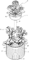
図1,図2は本発明による植物栽培装置を示し、植物Aを栽培可能な樹脂製の上下の栽培容器1,2と、各栽培容器1,2で栽培している植物Aの肥料成分や殺菌成分を水に溶解させた栽培用液体3を貯留可能な樹脂製タンク4とを備えていて、図2に示すように、立体花壇として設置できるように設けてある。Embodiments of the present invention will be described below with reference to the drawings.
1 and 2 show a plant cultivation apparatus according to the present invention, and upper and lower resin-made
前記タンク4は、栽培用液体3の貯留部5を平面視で円環状に形成できるように、図3に示すように、筒状の内周壁6と外周壁7とを同芯状に備え、その内周壁6と外周壁7との間を一連の環状に上向きに開口させた上向き開口部8に、上部栽培容器1とは別の別栽培容器、つまり、下部栽培容器2を設けてある。
The tank 4 includes a cylindrical inner
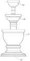
そして、上部栽培容器1をタンク4の上方に支持可能な中空円柱状の支持部材9を内周壁6の内側に同芯状に挿通して、支持部材9の下端に固定してあるベース板10をタンク底板11に固定し、支持部材9と内周壁6との隙間を円錐台形状のキャップ12で塞いである。
And the
前記上部栽培容器1とタンク4は、図3に示すように、連通路26を内側に形成している可撓性を備えた樹脂製チューブ13で接続して互いに連通するとともに、タンク4内の貯留液体(栽培用液体)3を上部栽培容器1に供給可能なポンプPを、そのチューブ13の途中に接続して、上部栽培容器1に自動灌水できるように設けてある。
As shown in FIG. 3, the
前記ポンプPは電動式のチューブポンプ(ペリスタポンプ)で構成してあり、貯留液体3をチューブ13を通して上部栽培容器1に供給する状態と、上部栽培容器1に供給した栽培用液体3のうちの目皿19の下側に溜まった余剰液体3a及び貯留液体3中でバブリングさせる曝気用空気を、チューブ13を通してタンク4内に流入させる状態とに自動切換自在な制御部を内装してある制御ユニット14と、制御ユニット14に対して、チューブポンプPの駆動間隔や吸引・吐出方向などの制御モードを設定するためのパネルスイッチ15とを設けて、上部栽培容器1に供給した栽培用液体3のうちの余剰液体3aを、チューブ13を通して、タンク4に還流可能に設けてある。
The pump P is composed of an electric tube pump (peristaltic pump), and the state of supplying the stored
前記チューブポンプPと制御ユニット14及びパネルスイッチ15はベース板10側に固定してあり、タンク底板11を部分的に上方に凹入させてベース板10との間に形成した収容空間16に収容して、タンク4の下側に一体に設け、収容空間16を開閉自在な蓋体17を、タンク4の外周形状に沿わせた形状で、装脱自在に設けてある。
尚、チューブポンプPと制御ユニット14などの電源として、図外の外部電源を使用するように設けてあるが、収容空間16などに収容した電池などの内部電源を使用しても良い。The tube pump P, the
Although an external power source (not shown) is used as the power source for the tube pump P and the
前記上部栽培容器1は、略円形の上向き椀状に形成するとともに内側に目皿19を設けて、その目皿19の上側に、植物Aを栽培するための培地18、例えば、一般に用いられる培養土、腐葉土、水苔等の自然培地の他、植物Aを簡便に交換できるように、バーミキュライト、パーライト、ロックウール、ハイドロボール、スポンジ等で予め成形してある人工培地を収容できるように構成してあり、その底面側に支持部材9を固定してタンク4の上方に支持するとともに、目皿19の容器下側に連通するチューブ接続用の口金部20を支持部材9の内側に突出するように設けてある。
The
前記チューブ13は、チューブポンプPとタンク4とを接続する上流部分21を、支持部材9と内周壁6との隙間を通して、内周壁6の側孔から貯留液体3中に入り込ませて、その開口端部を貯留液体3中に沈めるとともに、チューブポンプPと上部栽培容器1とを接続する下流部分22を、支持部材9に沿ってその内側に通して、口金部20に接続してある。
The
図4に示すように、チューブ13の上流部分21と下流部分22とを連絡するバイパス路30をバルブ31とともに設けることも可能である。タンク4中の貯留液体3を上部栽培容器1に供給するときは、ポンプPを駆動するとともにバルブ31を閉鎖しておく。この場合、通常の供給動作が行われる。上部栽培容器1に供給した栽培用液体3のうちの余剰液体3aをタンク4に戻すときは、ポンプPを停止するとともにバルブ31を開放する。この場合、余剰液体3aは、自重でチューブ13の上流部分21からバイパス路30を通って下流部分22に流れる。
このように、バルブ31付きのバイパス路30を設けると、貯留液体3をタンク4から上部栽培容器1に供給できるとともに、上部栽培容器1の余剰液体3aをタンク4に容易に戻すことができる。余剰液体3aをタンク4に戻すときは、ポンプPを駆動させる必要がないので、経済的である。しかも、ポンプPの吸引・吐出方向を変更しなくて良いので、安価なポンプを使用することができる。As shown in FIG. 4, a
Thus, when the
図5に示すように、上部栽培容器1から支持部材9内を通り、当該支持部材9および内周壁6を貫いてタンク4へと連絡する細管40を設けることも可能である。
このような構成であれば、上部栽培容器1の余剰液体3aは、細管40を通って、タンク4に少量ずつ戻される。従って、下部栽培容器2への水遣り作業を省略することができるとともに、時々ポンプPを駆動させるだけタンク4中の貯留液体3と上部栽培容器1中の余剰液体3aとのバランスを保つことができる。また、ポンプPの吸引・吐出方向を変更しなくても良いので、安価なポンプを使用することができる。As shown in FIG. 5, it is also possible to provide a
If it is such a structure, the
図6に示すように、チューブ13の上流部分21と下流部分22との間にクロス流路50をバルブ51、52、53、54とともに設けることも可能である。タンク4中の貯留液体3を上部栽培容器1に供給するときは、バルブ51、52を開放し、バルブ53、54を閉鎖した状態でポンプPを駆動する。この場合、通常の供給動作が行われる。上部栽培容器1に供給した栽培用液体3のうちの余剰液体3aをタンク4に戻すときは、ポンプPの駆動を維持したままバルブ51、52を閉鎖し、バルブ53、54を開放する。この場合、ポンプPの吸引側が下流部分22に、吐出側が上流部分21にそれぞれ接続されるので、貯留液体3および余剰液体3aの流動方向が逆転する。
このように、バルブ51、52、53、54付きのクロス流路50を設けると、貯留液体3をタンク4から上部栽培容器1に供給できるとともに、上部栽培容器1の余剰液体3aをタンク4に容易に戻すことができる。しかも、ポンプPの吸引・吐出方向を変更しなくても良いので、安価なポンプを使用することができる。As shown in FIG. 6, it is possible to provide a
Thus, when the
前記下部栽培容器2は、発泡スチロールを平面視で環状に成形したもので、上向き開口部8を通して貯留部5に同芯状に入り込ませてあり、空気や栽培用液体3を通すスポンジなどの多孔質材料製の有底筒状の成形培地23を挿脱自在に収容する円形の収容穴24の複数を周方向に並べて形成するとともに、各収容穴24の底部に貫通孔25を形成して、貯留部5の貯留液体3が貫通孔25を通して成形培地23の内側に自然供給されるように、成形培地23の内側に植えてある植物Aと共に貯留液体3の液面に浮かべて、フロート式の水耕方式で栽培できるように構成してある。
The lower cultivating
尚、下部栽培容器2は、貯留液体3の液面の高さに応じて、その浮かんでいる高さ位置が変わるので、下部栽培容器2の高さから貯留液体3の液量を知ることができる水位計にも兼用できる。
In addition, since the floating position of the
次に、本発明に係る植物栽培装置の別実施形態について説明する。この別実施形態では、植物栽培装置を構成する栽培容器を多段化している。図7は、多段化植物栽培容器の斜視図であり、図8は、多段化植物栽培容器の正面図である。なお、図示する別実施形態では、栽培容器61、62、63として、三段タイプの植物栽培装置を示しているが、段数は任意に変更可能である。
Next, another embodiment of the plant cultivation apparatus according to the present invention will be described. In this other embodiment, the cultivation container which comprises a plant cultivation apparatus is multistaged. FIG. 7 is a perspective view of a multistage plant cultivation container, and FIG. 8 is a front view of the multistage plant cultivation container. In addition, in another embodiment to show in figure, although the three-stage type plant cultivation apparatus is shown as the
最下段の栽培容器61にはポンプP(図示せず)が収納されており、栽培容器61中の貯留液体はポンプPによって最上段の栽培容器63に搬送される。栽培容器63に搬送された貯留液体のうち余剰液体がやがてオーバーフローし、その下の栽培容器62に供給される。次いで、栽培容器62に供給された貯留液体のうち余剰液体がやがてオーバーフローし、その下の栽培容器61に供給される。そして、栽培容器61に供給された貯留液体は、ポンプPによって再び最上段の栽培容器63に搬送される。このようにして、貯留液体は各栽培容器61、62、63を循環する。
A pump P (not shown) is accommodated in the
各栽培容器61、62、63の底部中央には、培地固定手段64、65、66を夫々設けることもできる。この場合、この培地固定手段64、65、66の窪み部に、植物を栽培するための培地71、72、73を填め込むことができる。培地71、72、73をスポンジ等の弾性体で構成すれば、培地固定手段64、65、66に挟持されるので、貯留液体によって流されたり、移動したりすることはない。なお、最下段を図3と同じく、フロート式の水耕方式とすれば、栽培容器61中の貯留液体の液量を知ることができる。
Medium fixing means 64, 65, 66 can also be provided at the center of the bottom of each of the
また、最下段の栽培容器61は、剛性を確保するため、内側に突出するドーム形状の底部67を有している。このため、植物栽培装置は姿勢が安定し、容易に倒れたりはしない。
Moreover, the
〔その他の実施形態〕
1.本発明による植物栽培装置は、タンクの上面をテーブルや椅子として使用できるように設けてあっても良い。
2.本発明による植物栽培装置は、タンクの上部や側部にポンプを一体に設けてあっても良い。
3.本発明による植物栽培装置は、栽培容器を載置支持可能な支持部や栽培容器を吊り下げ支持可能な支持部を設けてあっても良い。
4.本発明による植物栽培装置は、栽培容器をタンクの上方に支持可能な支持部を、タンクと略同径の筒体などで構成してあっても良い。
5.本発明による植物栽培装置は、栽培容器をタンクの下部に連通する連通路を設けて、その連通路に栽培用液体供給用のポンプを設けてあっても良い。
6.本発明による植物栽培装置は、栽培容器に供給した栽培用液体のうちの余剰液体を、自重でタンクに還流可能に設けてあっても良い。
7.本発明による植物栽培装置は、タンク内の貯留液体を栽培容器に供給可能なポンプとは別に、栽培容器に供給した液体のうちの余剰液体及び貯留液体中でバブリングさせる曝気用空気をタンク内に流入させるポンプを設けてあっても良い。[Other Embodiments]
1. The plant cultivation apparatus by this invention may be provided so that the upper surface of a tank can be used as a table or a chair.
2. In the plant cultivation apparatus according to the present invention, a pump may be integrally provided on an upper part or a side part of the tank.
3. The plant cultivation apparatus according to the present invention may be provided with a support part that can place and support the cultivation container and a support part that can support the cultivation container by suspending it.
4). In the plant cultivation apparatus according to the present invention, the support portion that can support the cultivation container above the tank may be formed of a cylindrical body having substantially the same diameter as the tank.
5. The plant cultivation apparatus according to the present invention may be provided with a communication path that connects the cultivation container to the lower part of the tank, and a pump for supplying the cultivation liquid may be provided in the communication path.
6). The plant cultivation apparatus according to the present invention may be provided so that excess liquid of the cultivation liquid supplied to the cultivation container can be returned to the tank by its own weight.
7). The plant cultivation apparatus according to the present invention has, in addition to the pump capable of supplying the storage liquid in the tank to the cultivation container, the excess liquid of the liquid supplied to the cultivation container and aeration air to be bubbled in the storage liquid in the tank. An inflow pump may be provided.
本発明に係る植物栽培装置は、設置スペースが少なくて済み、栽培容器とタンクとを一体に移動することができて扱い易い。このため、本発明の植物栽培装置は、業務用または家庭用を問わず、多種にわたる用途に使用することができる。 The plant cultivation apparatus according to the present invention requires little installation space, and can easily move the cultivation container and the tank so as to be handled. For this reason, the plant cultivation apparatus of this invention can be used for various uses regardless of business use or household use.
1 栽培容器
2 別栽培容器
3 栽培用液体(貯留液体)
3a 余剰液体
4 タンク
9 支持部
26 連通路
A 植物
P ポンプ(チューブポンプ)DESCRIPTION OF
3a surplus liquid 4
Claims (4)
前記栽培容器を前記タンクの上方に支持可能な支持部を前記タンクに設けるとともに、前記連通路を前記支持部に沿って設け、
前記ポンプを前記タンクと一体に設けてある植物栽培装置。A plant cultivation apparatus in which a pump capable of supplying the storage liquid in the tank to the cultivation container is provided in a communication path that connects the cultivation container capable of cultivating the plant and a tank capable of storing the cultivation liquid for the plant. Because
While providing the tank with a support part capable of supporting the cultivation container above the tank, the communication path is provided along the support part,
A plant cultivation apparatus in which the pump is provided integrally with the tank.
前記貯留液体を前記栽培容器に供給する状態と、前記栽培容器に供給した栽培用液体のうちの余剰液体及び前記貯留液体中でバブリングさせる曝気用空気を前記タンク内に流入させる状態とに切換自在なチューブポンプで構成してある請求の範囲第1項又は第2項記載の植物栽培装置。The pump,
Switchable between a state in which the stored liquid is supplied to the cultivation container and a state in which surplus liquid in the cultivation liquid supplied to the cultivation container and aeration air to be bubbled in the stored liquid are allowed to flow into the tank. The plant cultivation device according to claim 1 or 2, wherein the plant cultivation device comprises a simple tube pump.
Applications Claiming Priority (3)
| Application Number | Priority Date | Filing Date | Title |
|---|---|---|---|
| JP2004376440 | 2004-12-27 | ||
| JP2004376440 | 2004-12-27 | ||
| PCT/JP2005/023856 WO2006070783A1 (en) | 2004-12-27 | 2005-12-27 | Plant culturing device |
Publications (1)
| Publication Number | Publication Date |
|---|---|
| JPWO2006070783A1 true JPWO2006070783A1 (en) | 2008-06-12 |
Family
ID=36614897
Family Applications (1)
| Application Number | Title | Priority Date | Filing Date |
|---|---|---|---|
| JP2006550782A Pending JPWO2006070783A1 (en) | 2004-12-27 | 2005-12-27 | Plant cultivation equipment |
Country Status (7)
| Country | Link |
|---|---|
| US (1) | US20080263947A1 (en) |
| EP (1) | EP1832158B1 (en) |
| JP (1) | JPWO2006070783A1 (en) |
| KR (1) | KR100965472B1 (en) |
| CN (1) | CN101083905B (en) |
| TW (1) | TW200638861A (en) |
| WO (1) | WO2006070783A1 (en) |
Families Citing this family (5)
| Publication number | Priority date | Publication date | Assignee | Title |
|---|---|---|---|---|
| KR100826795B1 (en) * | 2008-01-10 | 2008-04-30 | 박기윤 | A flowerpot |
| TWM369027U (en) * | 2009-07-02 | 2009-11-21 | Univ Far East | Watering-hint flower pots by utilizing humidity sensing material |
| US20150282441A1 (en) * | 2014-04-04 | 2015-10-08 | Aaron Marshall | Irrigation apparatus and feeding system |
| CN105660347A (en) * | 2016-02-29 | 2016-06-15 | 湖州织里华宁园艺工程有限公司 | Circulation type suspension flowerpot assembly for water-culture plants |
| CN106576983A (en) * | 2016-12-15 | 2017-04-26 | 英业达科技有限公司 | Stretchable flowerpot device and potting soil filling device |
Citations (10)
| Publication number | Priority date | Publication date | Assignee | Title |
|---|---|---|---|---|
| JPS55178356U (en) | 1979-06-12 | 1980-12-22 | ||
| JPS61193753U (en) * | 1985-05-28 | 1986-12-02 | ||
| JPS63141522A (en) | 1986-08-22 | 1988-06-14 | 中村 恵子 | Automatic water feeding plant culture apparatus |
| JPH07115861A (en) | 1993-10-22 | 1995-05-09 | Hokushiyou:Kk | Planter |
| JPH07322782A (en) * | 1994-05-31 | 1995-12-12 | Takiron Co Ltd | Base irrigator for potting cultivation |
| JP3051768U (en) * | 1998-02-23 | 1998-09-02 | 道男 鈴木 | Flower stand with automatic watering device for houseplants |
| JPH1198929A (en) | 1997-09-26 | 1999-04-13 | Nippon Road Co Ltd:The | Rooftop greening system |
| JP2000050735A (en) * | 1998-08-11 | 2000-02-22 | City Planner:Kk | Planter capable of being taken care of by wheelchaired person |
| JP2002253054A (en) | 2001-02-28 | 2002-09-10 | Yoshiyasu Ikeda | Plant culture apparatus and method for culturing plant using the same |
| JP2004024029A (en) * | 2002-06-21 | 2004-01-29 | Suntry Flowers Ltd | Apparatus and method for cultivating plant |
Family Cites Families (11)
| Publication number | Priority date | Publication date | Assignee | Title |
|---|---|---|---|---|
| US4006559A (en) * | 1975-09-15 | 1977-02-08 | Carlyon Jr Richard A | Self-irrigating display rack for potted plants |
| JPS6374429A (en) * | 1986-09-18 | 1988-04-04 | 神戸企業株式会社 | Hydroponic facilities for leaf vegetables |
| US4899487A (en) * | 1988-01-12 | 1990-02-13 | Brownlee Richard W | Storage and display receptacle assembly |
| US4951416A (en) * | 1989-04-26 | 1990-08-28 | Gutridge Dale H | Nutrient supply system for hydroponic systems |
| US5276997A (en) * | 1992-06-01 | 1994-01-11 | Swearengin Michael L | Planter with built-in water distribution system |
| US5251399A (en) * | 1992-10-23 | 1993-10-12 | Rasmussen Von O | Vertical plant stand |
| US5440836A (en) * | 1993-03-16 | 1995-08-15 | Lee; Jong-Chul | Hydroponic device for plant cultivation |
| IL105601A (en) * | 1993-05-04 | 1997-06-10 | N C A Ltd | Plant holder |
| US5598662A (en) * | 1996-02-26 | 1997-02-04 | Droste; Donna A. | Pole garden and fountain |
| KR100332158B1 (en) * | 2000-02-14 | 2002-04-10 | 변복구 | Automatically cultivating device by layer-built |
| US6557297B2 (en) * | 2001-01-25 | 2003-05-06 | Richard L. Receveur | Adjustable water plant container support assembly |
-
2005
- 2005-12-27 CN CN200580043906.0A patent/CN101083905B/en not_active Expired - Fee Related
- 2005-12-27 EP EP05822576.4A patent/EP1832158B1/en not_active Not-in-force
- 2005-12-27 TW TW094146770A patent/TW200638861A/en not_active IP Right Cessation
- 2005-12-27 KR KR1020077015469A patent/KR100965472B1/en active IP Right Grant
- 2005-12-27 JP JP2006550782A patent/JPWO2006070783A1/en active Pending
- 2005-12-27 US US11/794,034 patent/US20080263947A1/en not_active Abandoned
- 2005-12-27 WO PCT/JP2005/023856 patent/WO2006070783A1/en active Application Filing
Patent Citations (10)
| Publication number | Priority date | Publication date | Assignee | Title |
|---|---|---|---|---|
| JPS55178356U (en) | 1979-06-12 | 1980-12-22 | ||
| JPS61193753U (en) * | 1985-05-28 | 1986-12-02 | ||
| JPS63141522A (en) | 1986-08-22 | 1988-06-14 | 中村 恵子 | Automatic water feeding plant culture apparatus |
| JPH07115861A (en) | 1993-10-22 | 1995-05-09 | Hokushiyou:Kk | Planter |
| JPH07322782A (en) * | 1994-05-31 | 1995-12-12 | Takiron Co Ltd | Base irrigator for potting cultivation |
| JPH1198929A (en) | 1997-09-26 | 1999-04-13 | Nippon Road Co Ltd:The | Rooftop greening system |
| JP3051768U (en) * | 1998-02-23 | 1998-09-02 | 道男 鈴木 | Flower stand with automatic watering device for houseplants |
| JP2000050735A (en) * | 1998-08-11 | 2000-02-22 | City Planner:Kk | Planter capable of being taken care of by wheelchaired person |
| JP2002253054A (en) | 2001-02-28 | 2002-09-10 | Yoshiyasu Ikeda | Plant culture apparatus and method for culturing plant using the same |
| JP2004024029A (en) * | 2002-06-21 | 2004-01-29 | Suntry Flowers Ltd | Apparatus and method for cultivating plant |
Also Published As
| Publication number | Publication date |
|---|---|
| KR20070092978A (en) | 2007-09-14 |
| KR100965472B1 (en) | 2010-06-24 |
| CN101083905B (en) | 2014-09-10 |
| TW200638861A (en) | 2006-11-16 |
| EP1832158B1 (en) | 2014-04-09 |
| EP1832158A4 (en) | 2011-04-27 |
| US20080263947A1 (en) | 2008-10-30 |
| TWI355889B (en) | 2012-01-11 |
| WO2006070783A1 (en) | 2006-07-06 |
| EP1832158A1 (en) | 2007-09-12 |
| CN101083905A (en) | 2007-12-05 |
Similar Documents
| Publication | Publication Date | Title |
|---|---|---|
| US9357715B2 (en) | Vertical planter | |
| KR101399512B1 (en) | Hydroponic culture apparatus | |
| JP4777909B2 (en) | Plant cultivation equipment | |
| US5502924A (en) | Planter assembly having automatic water-feeding and drying intervals | |
| US20120186153A1 (en) | Device, system and methods for hydroponic gardening | |
| JPWO2006070783A1 (en) | Plant cultivation equipment | |
| KR20150084319A (en) | Hydroponic flowerpot | |
| US5743290A (en) | Multi-purpose automatic filling and leveling liquid basin with liquid transfer | |
| KR101702445B1 (en) | Water culture apparatus | |
| JP4898161B2 (en) | flower pot | |
| CN217117172U (en) | Tidal water planting pot and stereoscopic planting device | |
| JPH11192031A (en) | Flowerpot with automatic water supply | |
| KR20100129974A (en) | Flowerpot unit for water culture and moudle type flowerpot using the same | |
| JPH05137468A (en) | Desk type automatic irrigator for cultivating plant | |
| KR102034639B1 (en) | Piling up type plant factory | |
| JP4977306B2 (en) | Automatic water supply device and automatic water supply system for plant cultivation containers | |
| JP2000333544A (en) | Water tank equipped with automatic water supply device for plant cultivation | |
| CN214801431U (en) | Water supply installation cultivated in a pot | |
| KR102109776B1 (en) | Water supply device and flower pot with the same | |
| JPH04129756U (en) | Water level adjustment structure in irrigation cultivation method | |
| JP2003038032A (en) | Cut flower preservation apparatus and cut flower preservation method | |
| JP2023090639A (en) | Hydroponic culture system | |
| JP2004008178A (en) | Connectable type container | |
| JP2000224932A (en) | Device for water culture of leaf vegetables | |
| KR20210034774A (en) | Plant breeding water supply |
Legal Events
| Date | Code | Title | Description |
|---|---|---|---|
| A621 | Written request for application examination |
Free format text: JAPANESE INTERMEDIATE CODE: A621 Effective date: 20080527 |
|
| A711 | Notification of change in applicant |
Free format text: JAPANESE INTERMEDIATE CODE: A712 Effective date: 20090423 |
|
| A131 | Notification of reasons for refusal |
Free format text: JAPANESE INTERMEDIATE CODE: A131 Effective date: 20110623 |
|
| A521 | Written amendment |
Free format text: JAPANESE INTERMEDIATE CODE: A523 Effective date: 20110819 |
|
| A131 | Notification of reasons for refusal |
Free format text: JAPANESE INTERMEDIATE CODE: A131 Effective date: 20120112 |
|
| A521 | Written amendment |
Free format text: JAPANESE INTERMEDIATE CODE: A523 Effective date: 20120312 |
|
| A02 | Decision of refusal |
Free format text: JAPANESE INTERMEDIATE CODE: A02 Effective date: 20121129 |
|
| A521 | Written amendment |
Free format text: JAPANESE INTERMEDIATE CODE: A523 Effective date: 20130228 |
|
| A521 | Written amendment |
Free format text: JAPANESE INTERMEDIATE CODE: A821 Effective date: 20130228 |
|
| A911 | Transfer to examiner for re-examination before appeal (zenchi) |
Free format text: JAPANESE INTERMEDIATE CODE: A911 Effective date: 20130322 |
|
| A521 | Written amendment |
Free format text: JAPANESE INTERMEDIATE CODE: A523 Effective date: 20141027 |