EP1831663B1 - Resonatormesseinrichtung und verfahren damit - Google Patents
Resonatormesseinrichtung und verfahren damit Download PDFInfo
- Publication number
- EP1831663B1 EP1831663B1 EP05823948A EP05823948A EP1831663B1 EP 1831663 B1 EP1831663 B1 EP 1831663B1 EP 05823948 A EP05823948 A EP 05823948A EP 05823948 A EP05823948 A EP 05823948A EP 1831663 B1 EP1831663 B1 EP 1831663B1
- Authority
- EP
- European Patent Office
- Prior art keywords
- pressure
- resonator
- chamber
- gain
- measurement
- Prior art date
- Legal status (The legal status is an assumption and is not a legal conclusion. Google has not performed a legal analysis and makes no representation as to the accuracy of the status listed.)
- Ceased
Links
Images
Classifications
-
- G—PHYSICS
- G01—MEASURING; TESTING
- G01L—MEASURING FORCE, STRESS, TORQUE, WORK, MECHANICAL POWER, MECHANICAL EFFICIENCY, OR FLUID PRESSURE
- G01L9/00—Measuring steady of quasi-steady pressure of fluid or fluent solid material by electric or magnetic pressure-sensitive elements; Transmitting or indicating the displacement of mechanical pressure-sensitive elements, used to measure the steady or quasi-steady pressure of a fluid or fluent solid material, by electric or magnetic means
- G01L9/0001—Transmitting or indicating the displacement of elastically deformable gauges by electric, electro-mechanical, magnetic or electro-magnetic means
- G01L9/0008—Transmitting or indicating the displacement of elastically deformable gauges by electric, electro-mechanical, magnetic or electro-magnetic means using vibrations
- G01L9/0019—Transmitting or indicating the displacement of elastically deformable gauges by electric, electro-mechanical, magnetic or electro-magnetic means using vibrations of a semiconductive element
-
- G—PHYSICS
- G01—MEASURING; TESTING
- G01L—MEASURING FORCE, STRESS, TORQUE, WORK, MECHANICAL POWER, MECHANICAL EFFICIENCY, OR FLUID PRESSURE
- G01L21/00—Vacuum gauges
- G01L21/16—Vacuum gauges by measuring variation of frictional resistance of gases
- G01L21/22—Vacuum gauges by measuring variation of frictional resistance of gases using resonance effects of a vibrating body; Vacuum gauges of the Klumb type
-
- G—PHYSICS
- G01—MEASURING; TESTING
- G01L—MEASURING FORCE, STRESS, TORQUE, WORK, MECHANICAL POWER, MECHANICAL EFFICIENCY, OR FLUID PRESSURE
- G01L27/00—Testing or calibrating of apparatus for measuring fluid pressure
- G01L27/007—Malfunction diagnosis, i.e. diagnosing a sensor defect
-
- G—PHYSICS
- G01—MEASURING; TESTING
- G01L—MEASURING FORCE, STRESS, TORQUE, WORK, MECHANICAL POWER, MECHANICAL EFFICIENCY, OR FLUID PRESSURE
- G01L9/00—Measuring steady of quasi-steady pressure of fluid or fluent solid material by electric or magnetic pressure-sensitive elements; Transmitting or indicating the displacement of mechanical pressure-sensitive elements, used to measure the steady or quasi-steady pressure of a fluid or fluent solid material, by electric or magnetic means
- G01L9/0001—Transmitting or indicating the displacement of elastically deformable gauges by electric, electro-mechanical, magnetic or electro-magnetic means
- G01L9/0008—Transmitting or indicating the displacement of elastically deformable gauges by electric, electro-mechanical, magnetic or electro-magnetic means using vibrations
-
- G—PHYSICS
- G01—MEASURING; TESTING
- G01N—INVESTIGATING OR ANALYSING MATERIALS BY DETERMINING THEIR CHEMICAL OR PHYSICAL PROPERTIES
- G01N2291/00—Indexing codes associated with group G01N29/00
- G01N2291/02—Indexing codes associated with the analysed material
- G01N2291/028—Material parameters
- G01N2291/02872—Pressure
-
- G—PHYSICS
- G01—MEASURING; TESTING
- G01N—INVESTIGATING OR ANALYSING MATERIALS BY DETERMINING THEIR CHEMICAL OR PHYSICAL PROPERTIES
- G01N2291/00—Indexing codes associated with group G01N29/00
- G01N2291/02—Indexing codes associated with the analysed material
- G01N2291/028—Material parameters
- G01N2291/02881—Temperature
Definitions
- the invention relates to a device and a method for fault detection of a measuring device comprising a resonator and means for measuring a resonance frequency of the resonator.
- the measuring device comprises for example a fluid pressure sensor.
- the invention finds particular utility in aeronautics where pressure measurements are essential for the flight control of an aircraft. Indeed, the altitude of a flight level required for an aircraft is determined by the static pressure of the air surrounding the aircraft. In addition, as air traffic increases, traffic control authorities seek to reduce the gap between two neighboring flight levels. Detecting a defect in a pressure sensor is essential to guarantee the safety of air traffic.
- the invention can also be implemented for other devices using a resonator, for example in an accelerometer as described in the French patent application. FR 2 848 298 , a gyrometer as described in the French patent application FR 2,834,055 or in a time base. The remainder of the description will be made with reference to an air pressure sensor without, of course, limiting the invention.
- pressure sensors In order to measure the pressure of the ambient air, pressure sensors are commonly used comprising a chamber maintained at a reference pressure generally close to the vacuum.
- An example of this type of sensor is described in the French patent application FR 2,687,783 .
- the pressure sensor measures a pressure difference between the chamber and the air.
- the guarantee of accuracy in the measurement of pressure depends essentially on the maintenance of the vacuum prevailing inside the chamber throughout the lifetime of a sensor, or at least between two calibrations of the pressure sensor.
- Several phenomena can degrade the vacuum in the chamber, such as leaks that may occur at the junctions of different components of the chamber walls or degassing walls or components in the chamber.
- the pressure sensor described in the French patent application FR 2,687,783 has a resonator, one end of which is subject to effort depends on the pressure difference between the inside of the chamber and the ambient air.
- the principle of pressure measurement is to measure the resonance frequency of the resonator.
- the object of the invention is to improve the knowledge of the precision level of the pressure sensor during its use and to avoid the need to recalibrate the sensor periodically in a preventive manner.
- Another object of the invention is to maintain a level of precision of the order of 0.1 hPa.
- the subject of the invention is a measuring device comprising a resonator and means for measuring a resonance frequency of the resonator, characterized in that it comprises means delivering information representative of the quality coefficient of the resonator. at the resonant frequency, the information to detect a defect of the device.
- the invention also relates to a method of using an air pressure measuring device comprising a pressure sensor and a chamber maintained at a reference pressure, the pressure sensor measuring a pressure difference between the chamber. and the air, the sensor comprising a resonator excited by an oscillation controlled by automatic amplitude control means, characterized in that the device comprises means for detecting a pressure variation in the chamber and in that the method consists in comparing a first gain of the automatic control of the amplitude of the excitation measured during the measurement of pressure with a second gain of the automatic control of the amplitude of the excitation calculated at the frequency of the excitation measured from parameters defined during a calibration of the device so as to detect a fault of the device when the difference between the two gains is greater than one given value.
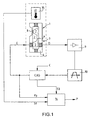
- the figure 1 represents an air pressure measuring device comprising a pressure sensor 1 and a chamber 2 maintained at a reference pressure, generally close to the vacuum.
- the pressure sensor 1 measures a pressure difference between the chamber 2 and the air surrounding the pressure sensor 1.
- the device comprises a resonator 3 and means for measuring a resonance frequency of the resonator 3.
- the resonator 3 is for example made by means of a silicon blade 4 that can resonate under the effect of a electric excitation signal E.
- the silicon blade 4 is located in the chamber 2.
- the silicon blade 4 is embedded at one of its ends 5 in a body 6 of the resonator 3 and at the other of its ends 7 on a thin wall 8 of the chamber 2.
- the wall 8 is subjected on one of its faces to the pressure of the air, pressure to be measured, and on the other of its faces to the pressure of the chamber 2.
- the wall 8 is deformed according to the pressure difference between the chamber 2 and the air. This deformation of the wall 8 causes a stress in the silicon wafer 4.
- the stress changes as a function of the pressure difference between the air and the chamber 2.
- the resonance frequency of the silicon wafer 4 is therefore also a function of the difference in pressure between the air and the chamber 2.
- a more detailed explanation of the realization of this example of resonator can be obtained by reading the French patent application FR 2,687,783 . It is of course possible to use another type of pressure sensor using a resonator and wherein the resonator is located outside a chamber maintained at a reference pressure.
- the detection of the resonance is done by capacitive effect between the silicon wafer 4 and the body 6 of the resonator 3 by means of a signal electrical D taken at the body 6 of the resonator 3.
- the electrical signal D is amplified by an amplifier 9 and then filtered by means of a bandpass filter 10 to retain only the resonance frequency and be delivered to automatic control means of the amplitude of the excitation signal E, means commonly called automatic gain control and carrying the CAG mark on the figure 1 .
- the automatic gain control is controlled by a set point C.
- the automatic gain control delivers the excitation signal E.
- the excitation signal E forms the signal Fp used by a computer 14 to determine the air pressure.
- the device further comprises means 15 for measuring the temperature of the air.
- the means 15 comprise, for example, a negative temperature coefficient resistor.
- the means 15 deliver a signal St to the computer 14 to correct the air pressure measurement. This correction is for example calculated as a function of the signal St and of the signal Fp by means of a polynomial function defined during a calibration of the device. This calibration is carried out using a pressure measurement campaign carried out at different temperatures.
- the device comprises means for detecting a pressure variation in the chamber 2.
- These means advantageously provide information representative of the quality coefficient of the resonator at the resonance frequency, for example in the form of a gain.
- S3 automatic gain control issued to the computer 14 to detect a fault of the device.
- the signal S3 was measured for each measurement of pressure carried out. The measurements made during the calibration make it possible to calculate, for any subsequent measurement of pressure, a value that the signal S3 should take if the pressure of the chamber remains unchanged.
- the signal S3 is a function of the signals Fp and St and that this function can be approximated by means of a polynomial function.
- a method consists in comparing a first signal S3 measured during the pressure measurement with a second signal S3 calculated from parameters defined during the calibration of the device and as a function of the measured signals Fp and St. The device is then declared in default if the difference between the measured signal S3 and the calculated signal S3 is greater than a given value. The comparison and the different calculations are carried out by the computer 14.
- the pressure P is calculated as a function of the measured signals Fp, St and S3.
- This calculation can be done by means of a function whose parameters are defined during the calibration phase.
- the function is here again for example polynomial.
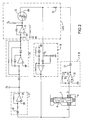
- the figure 2 represents an embodiment of a part of the diagram of the figure 1 . To avoid overloading the figure 2 the computer 14 and the means 15 for measuring the temperature of the air have not been shown.
- the amplifier 9 and the bandpass filter 10 are formed around an operational amplifier 20 driven on its inverting input by the signal D.
- the non-inverting input of the operational amplifier 20 is connected to a ground.
- a feedback of the operational amplifier is formed by a resistor 21 and a capacitor 22 connected in parallel between the inverting input and the output of the operational amplifier 20.
- a capacitor 23 is connected to the output of the operational amplifier 20 to provide a signal to the AGC automatic gain control which can weaken this signal by means of a resistor 24 and a field effect transistor 25.
- the weakened signal is biased and shaped by passing through a circuit 26.
- bias voltage is a voltage V 0 supplied to the circuit 26.
- the output of the circuit 26 provides the excitation signal E.
- the signal Fp is formed from the signal E through a circuit 27 whose function is to depolarize the signal.
- signal E by means of a capacitor 28 and amplifying the signal E by means of an operational amplifier 29.
- the signal Fp is then rectified by means of of a circuit 30 to be delivered to automatic gain control AGC.
- the automatic gain control AGC is controlled by a set point C.
- the automatic gain control AGC comprises a first integration stage carried out around an operational amplifier 31 whose output forms the signal S3 which drives a gate G of the effect transistor field 25.
Landscapes
- Physics & Mathematics (AREA)
- General Physics & Mathematics (AREA)
- Health & Medical Sciences (AREA)
- Chemical & Material Sciences (AREA)
- Engineering & Computer Science (AREA)
- Analytical Chemistry (AREA)
- Biomedical Technology (AREA)
- Measuring Fluid Pressure (AREA)
- Measurement Of Resistance Or Impedance (AREA)
- Testing Electric Properties And Detecting Electric Faults (AREA)
- Measurement Of Mechanical Vibrations Or Ultrasonic Waves (AREA)
Claims (9)
- Messvorrichtung, die einen Resonator (3) und Mittel zum Messen einer Resonanzfrequenz des Resonators (3) enthält, wobei das Prinzip der Messung darin besteht, die Resonanzfrequenz zu messen, dadurch gekennzeichnet, dass sie Mittel enthält, die eine Information (S3) liefern, die den Gütekoeffizienten des Resonators (3) bei der Resonanzfrequenz repräsentiert, wobei die Information (S3) ermöglicht, einen Defekt der Vorrichtung zu erfassen.
- Vorrichtung nach Anspruch 1, dadurch gekennzeichnet, dass sie einen Drucksensor (1) und eine Kammer (2), die auf einem Referenzdruck gehalten wird, enthält, wobei der Drucksensor (1) eine Druckdifferenz zwischen der Kammer (2) und der Luft misst.
- Vorrichtung nach Anspruch 2, dadurch gekennzeichnet, dass die Mittel zum Messen einer Resonanzfrequenz des Resonators Mittel (CAG) zum automatischen Steuern der Amplitude einer Erregungsoszillation (E) des Resonators (3) enthalten und dass ein Verstärkungsfaktor (S3) der automatischen Steuerung (CAG) der Amplitude die Information bildet, die den Gütekoeffizienten des Resonators (3) repräsentiert.
- Vorrichtung nach einem der vorhergehenden Ansprüche, dadurch gekennzeichnet, dass sie Mittel (15) zum Messen der Temperatur enthält.
- Vorrichtung nach einem der vorhergehenden Ansprüche, dadurch gekennzeichnet, dass sie Mittel (14) zum Korrigieren des durch den Drucksensor (1) gemessenen Drucks als Funktion einer Information, die von den Mitteln (CAG) zum Erfassen einer Druckänderung in der Kammer (2) stammen, enthält.
- Vorrichtung nach Anspruch 1, dadurch gekennzeichnet, dass sie Mittel zum Messen einer Beschleunigung enthält.
- Verfahren zum Verwenden einer Vorrichtung zum Messen des Luftdrucks, die einen Drucksensor (1) und eine Kammer (2), die auf einem Referenzdruck gehalten wird, enthält, wobei der Drucksensor (1) eine Druckdifferenz zwischen der Kammer (2) und der Luft misst und wobei der Drucksensor (1) einen Resonator (3) enthält, der durch eine durch Mittel (CAG) zum automatischen Steuern der Amplitude gesteuerte Oszillation (E) erregt wird, wobei das Messprinzip darin besteht, die Resonanzfrequenz zu messen, dadurch gekennzeichnet, dass die Vorrichtung Mittel (CAG) zum Erfassen einer Druckänderung in der Kammer (2) enthält und dass das Verfahren darin besteht, einen ersten Verstärkungsfaktor (S3 gemessen) der automatischen Steuerung der Amplitude der gemessenen Erregung, die bei der Druckmessung gemessen wird, mit einem zweiten Verstärkungsfaktor (S3 berechnet) der automatischen Steuerung der Amplitude der Erregung, die bei der gemessenen Erregungsfrequenz anhand von Parametern berechnet wird, die bei einer Kalibrierung der Vorrichtung definiert werden, zu vergleichen, um einen Defekt der Vorrichtung zu erfassen, wenn die Differenz zwischen den zwei Verstärkungsfaktoren größer als ein gegebener Wert ist.
- Verfahren nach Anspruch 7, dadurch gekennzeichnet, dass die Vorrichtung Mittel (15) zum Messen der Temperatur enthält und dass das Verfahren darin besteht, den zweiten Verstärkungsfaktor (S3 berechnet) als Funktion der Frequenz (Fp) der Erregung (E) und der bei der Erregung gemessenen Temperatur (St) zu berechnen.
- Verfahren nach einem der Ansprüche 7 oder 8, dadurch gekennzeichnet, dass es darin besteht, die Messung der Druckdifferenz zwischen der Kammer (2) und der Luft als Funktion der Differenz zwischen den zwei Verstärkungsfaktoren zu korrigieren.
Applications Claiming Priority (3)
| Application Number | Priority Date | Filing Date | Title |
|---|---|---|---|
| FR0413965A FR2888929A1 (fr) | 2004-12-27 | 2004-12-27 | Dispositif et procede permettant la detection de defaut d'un dispositif de mesure de pression d'air |
| FR0500591A FR2888930B1 (fr) | 2004-12-27 | 2005-01-20 | Dispositfi de mesure a resonateur et procede mettant en oeuvre le dispositif |
| PCT/EP2005/056961 WO2006069937A1 (fr) | 2004-12-27 | 2005-12-20 | Dispositif de mesure a resonateur et procede mettant en oeuvre le dispositif |
Publications (2)
| Publication Number | Publication Date |
|---|---|
| EP1831663A1 EP1831663A1 (de) | 2007-09-12 |
| EP1831663B1 true EP1831663B1 (de) | 2008-09-10 |
Family
ID=35961314
Family Applications (1)
| Application Number | Title | Priority Date | Filing Date |
|---|---|---|---|
| EP05823948A Ceased EP1831663B1 (de) | 2004-12-27 | 2005-12-20 | Resonatormesseinrichtung und verfahren damit |
Country Status (6)
| Country | Link |
|---|---|
| US (1) | US7798005B2 (de) |
| EP (1) | EP1831663B1 (de) |
| DE (1) | DE602005009746D1 (de) |
| FR (1) | FR2888930B1 (de) |
| NO (1) | NO20073953L (de) |
| WO (1) | WO2006069937A1 (de) |
Cited By (1)
| Publication number | Priority date | Publication date | Assignee | Title |
|---|---|---|---|---|
| FR2992418A1 (fr) * | 2012-06-22 | 2013-12-27 | Thales Sa | Capteur a element vibrant dans une cavite, a detection integree d anomalies |
Families Citing this family (14)
| Publication number | Priority date | Publication date | Assignee | Title |
|---|---|---|---|---|
| US8516895B2 (en) * | 2009-10-08 | 2013-08-27 | GM Global Technology Operations LLC | In-cylinder pressure sensor diagnostic systems and methods |
| US20110133755A1 (en) * | 2009-12-08 | 2011-06-09 | Delphi Technologies, Inc. | System and Method of Occupant Detection with a Resonant Frequency |
| PL2458357T5 (pl) * | 2010-11-29 | 2018-03-30 | Air Products And Chemicals, Inc. | Sposób i urządzenie do mierzenia ciśnienia gazu |
| ES2749877T3 (es) | 2010-11-29 | 2020-03-24 | Air Prod & Chem | Método y aparato de medición del peso molecular de un gas |
| EP2458348B1 (de) | 2010-11-29 | 2013-08-14 | Air Products And Chemicals, Inc. | Verfahren und Vorrichtung zum Messen der Massendurchflussrate eines Gases |
| FR2977676B1 (fr) | 2011-07-08 | 2013-08-02 | Thales Sa | Micro-systeme vibrant a boucle de controle automatique de gain, a controle integre du facteur de qualite |
| PL2667160T3 (pl) | 2012-05-24 | 2021-05-04 | Air Products And Chemicals, Inc. | Sposób i urządzenie do regulowania masowego natężenia przepływu gazu |
| PL2667159T3 (pl) | 2012-05-24 | 2022-05-02 | Air Products And Chemicals, Inc. | Sposób oraz urządzenie dla mierzenia masowego natężenia przepływu gazu |
| PL2667162T3 (pl) | 2012-05-24 | 2016-03-31 | Air Prod & Chem | Sposób oraz urządzenie do mierzenia właściwości fizycznych płynów dwufazowych |
| EP2667277B1 (de) | 2012-05-24 | 2017-12-27 | Air Products And Chemicals, Inc. | Verfahren und Vorrichtung zur Bereitstellung einer Gasmischung |
| PL2667176T3 (pl) | 2012-05-24 | 2015-07-31 | Air Prod & Chem | Urządzenie do mierzenia rzeczywistej zawartości butli z gazem pod ciśnieniem |
| EP2667276B1 (de) | 2012-05-24 | 2017-11-08 | Air Products And Chemicals, Inc. | Verfahren und Vorrichtung zur Bereitstellung einer Gasmischung |
| CN103636142A (zh) * | 2012-06-14 | 2014-03-12 | 华为终端有限公司 | 用于移动设备的气压校准方法、校准设备以及移动设备 |
| EP3462155B1 (de) * | 2012-09-25 | 2020-04-29 | ams International AG | Mems-resonator-drucksensor |
Family Cites Families (13)
| Publication number | Priority date | Publication date | Assignee | Title |
|---|---|---|---|---|
| US5009108A (en) * | 1988-09-16 | 1991-04-23 | Yokogawa Electric Corporation | Vibrating type transducer |
| US5165289A (en) * | 1990-07-10 | 1992-11-24 | Johnson Service Company | Resonant mechanical sensor |
| FR2687783B1 (fr) * | 1992-02-20 | 1994-05-20 | Sextant Avionique | Micro-capteur de pression. |
| US5546810A (en) * | 1993-07-06 | 1996-08-20 | Seiko Epson Corporation | Pressure measuring device and method using quartz resonators |
| US5458000A (en) * | 1993-07-20 | 1995-10-17 | Honeywell Inc. | Static pressure compensation of resonant integrated microbeam sensors |
| FI101018B (sv) * | 1996-12-13 | 1998-03-31 | Balzers And Leybold Instrument | Förfarande och anordning för elektronisk kompensation av missvisning t ill följd av resonans hos en kapacitiv tryckgivare |
| US6085594A (en) * | 1998-09-04 | 2000-07-11 | The United States Of America As Represented By The Administrator Of The National Aeronautics And Space Administration | High resolution and large dynamic range resonant pressure sensor based on Q-factor measurement |
| US6584845B1 (en) * | 1999-02-10 | 2003-07-01 | California Institute Of Technology | Inertial sensor and method of use |
| US6367786B1 (en) * | 1999-06-07 | 2002-04-09 | California Institute Of Technology | Micromachined double resonator |
| FR2834055B1 (fr) | 2001-12-20 | 2004-02-13 | Thales Sa | Capteur inertiel micro-usine pour la mesure de mouvements de rotation |
| FR2848298B1 (fr) | 2002-12-10 | 2005-03-11 | Thales Sa | Accelerometre a poutre vibrante |
| ITTO20050316A1 (it) * | 2005-05-10 | 2006-11-11 | Varian Spa | Sensore di pressione |
| US7444878B1 (en) * | 2006-10-30 | 2008-11-04 | Northrop Grumman Systems Corporation | Resonant frequency pressure sensor |
-
2005
- 2005-01-20 FR FR0500591A patent/FR2888930B1/fr not_active Expired - Lifetime
- 2005-12-20 WO PCT/EP2005/056961 patent/WO2006069937A1/fr not_active Ceased
- 2005-12-20 US US11/722,954 patent/US7798005B2/en active Active
- 2005-12-20 EP EP05823948A patent/EP1831663B1/de not_active Ceased
- 2005-12-20 DE DE602005009746T patent/DE602005009746D1/de not_active Expired - Lifetime
-
2007
- 2007-07-27 NO NO20073953A patent/NO20073953L/no not_active Application Discontinuation
Cited By (2)
| Publication number | Priority date | Publication date | Assignee | Title |
|---|---|---|---|---|
| FR2992418A1 (fr) * | 2012-06-22 | 2013-12-27 | Thales Sa | Capteur a element vibrant dans une cavite, a detection integree d anomalies |
| WO2013189700A1 (fr) * | 2012-06-22 | 2013-12-27 | Thales | Capteur a element vibrant dans une cavite, a detection integree d'anomalies |
Also Published As
| Publication number | Publication date |
|---|---|
| US7798005B2 (en) | 2010-09-21 |
| FR2888930B1 (fr) | 2007-08-31 |
| NO20073953L (no) | 2007-07-27 |
| DE602005009746D1 (de) | 2008-10-23 |
| WO2006069937A1 (fr) | 2006-07-06 |
| EP1831663A1 (de) | 2007-09-12 |
| US20080184804A1 (en) | 2008-08-07 |
| FR2888930A1 (fr) | 2007-01-26 |
Similar Documents
| Publication | Publication Date | Title |
|---|---|---|
| EP1831663B1 (de) | Resonatormesseinrichtung und verfahren damit | |
| EP0711956A1 (de) | Aktive Regeleinrichtung der Verbrennungsinstabilität und der Entkohlung eines Brennstoffeinspritzventils | |
| EP1247104B1 (de) | MULTIFUNKTIONALE SONDE FüR EIN LUFTFAHRZEUG | |
| US10288559B2 (en) | Gas concentration sensor with improved accuracy | |
| FR3037142A1 (fr) | Dispositif de mesure de pression a fiabilite amelioree et procede de calibrage associe | |
| EP2544011A1 (de) | Schwingendes Mikrosystem mit einer Schleife zur automatischen Verstärkungskontrolle mit integrierter Kontrolle des Qualitätsfaktors | |
| WO2009103419A1 (fr) | Procédé d'étalonnage d'un capteur de mesure | |
| KR100734474B1 (ko) | 스트라이 센서를 이용하여 오일 및 가스 윤활 장치를 모니터하기 위한 방법 및 장치 | |
| US11796468B2 (en) | Gas measurement device and gas measurement method | |
| EP1797396B1 (de) | Skalenfaktorstabilisierter festkörper-laserkreisel | |
| CA3081862C (fr) | Systeme d'evaluation de colmatage d'un filtre equipant un aeronef, aeronef comportant un tel systeme d'evaluation et methode associee | |
| EP4269953B1 (de) | Messung des durchflusses durch elektrische impedanzen piezoelektrischer wandler | |
| EP0932036B1 (de) | Permeameter mit grossem Messbereich | |
| EP2240676B1 (de) | Verfahren zur erkennung von stromimpulsen und zur verwaltung des betriebs eines motors | |
| FR3046154A1 (fr) | Procede d'amplification par un resonateur mecanique. | |
| FR2888929A1 (fr) | Dispositif et procede permettant la detection de defaut d'un dispositif de mesure de pression d'air | |
| EP2604981B1 (de) | Sensor mit Selbsttestmitteln | |
| EP3330680A1 (de) | Thermisches massendurchflussmessgerät | |
| JPH10509800A (ja) | ガス検知器 | |
| FR2905468B1 (fr) | Capteur d'ecoulement d'air thermique numerique integre. | |
| EP2310815B1 (de) | Impedanzsensor zur messung der akustischen eingangsimpedanz eines wellenleiters | |
| US7299676B1 (en) | Acoustic pressure calibrator | |
| BE1026619B1 (fr) | Systeme de mesure pour turbomachine | |
| CN217738994U (zh) | 一种激光甲烷传感器及燃气监测设备 | |
| EP2373965B2 (de) | Verfahren zum schätzen einer strahltemperatur in einem strahltriebwerk |
Legal Events
| Date | Code | Title | Description |
|---|---|---|---|
| PUAI | Public reference made under article 153(3) epc to a published international application that has entered the european phase |
Free format text: ORIGINAL CODE: 0009012 |
|
| 17P | Request for examination filed |
Effective date: 20070621 |
|
| AK | Designated contracting states |
Kind code of ref document: A1 Designated state(s): CH DE GB LI |
|
| DAX | Request for extension of the european patent (deleted) | ||
| RBV | Designated contracting states (corrected) |
Designated state(s): CH DE GB LI |
|
| GRAP | Despatch of communication of intention to grant a patent |
Free format text: ORIGINAL CODE: EPIDOSNIGR1 |
|
| GRAS | Grant fee paid |
Free format text: ORIGINAL CODE: EPIDOSNIGR3 |
|
| GRAA | (expected) grant |
Free format text: ORIGINAL CODE: 0009210 |
|
| AK | Designated contracting states |
Kind code of ref document: B1 Designated state(s): CH DE GB LI |
|
| REG | Reference to a national code |
Ref country code: GB Ref legal event code: FG4D Free format text: NOT ENGLISH |
|
| REG | Reference to a national code |
Ref country code: CH Ref legal event code: EP |
|
| REF | Corresponds to: |
Ref document number: 602005009746 Country of ref document: DE Date of ref document: 20081023 Kind code of ref document: P |
|
| PLBE | No opposition filed within time limit |
Free format text: ORIGINAL CODE: 0009261 |
|
| STAA | Information on the status of an ep patent application or granted ep patent |
Free format text: STATUS: NO OPPOSITION FILED WITHIN TIME LIMIT |
|
| 26N | No opposition filed |
Effective date: 20090611 |
|
| PGFP | Annual fee paid to national office [announced via postgrant information from national office to epo] |
Ref country code: CH Payment date: 20191213 Year of fee payment: 15 |
|
| REG | Reference to a national code |
Ref country code: CH Ref legal event code: PL |
|
| PG25 | Lapsed in a contracting state [announced via postgrant information from national office to epo] |
Ref country code: CH Free format text: LAPSE BECAUSE OF NON-PAYMENT OF DUE FEES Effective date: 20201231 Ref country code: LI Free format text: LAPSE BECAUSE OF NON-PAYMENT OF DUE FEES Effective date: 20201231 |
|
| P01 | Opt-out of the competence of the unified patent court (upc) registered |
Effective date: 20230427 |
|
| PGFP | Annual fee paid to national office [announced via postgrant information from national office to epo] |
Ref country code: GB Payment date: 20231116 Year of fee payment: 19 |
|
| PGFP | Annual fee paid to national office [announced via postgrant information from national office to epo] |
Ref country code: DE Payment date: 20231114 Year of fee payment: 19 |
|
| REG | Reference to a national code |
Ref country code: DE Ref legal event code: R119 Ref document number: 602005009746 Country of ref document: DE |
|
| GBPC | Gb: european patent ceased through non-payment of renewal fee |
Effective date: 20241220 |
|
| PG25 | Lapsed in a contracting state [announced via postgrant information from national office to epo] |
Ref country code: DE Free format text: LAPSE BECAUSE OF NON-PAYMENT OF DUE FEES Effective date: 20250701 |
|
| PG25 | Lapsed in a contracting state [announced via postgrant information from national office to epo] |
Ref country code: GB Free format text: LAPSE BECAUSE OF NON-PAYMENT OF DUE FEES Effective date: 20241220 |