EP1830429B1 - Bleiakkumulator - Google Patents
Bleiakkumulator Download PDFInfo
- Publication number
- EP1830429B1 EP1830429B1 EP07001855A EP07001855A EP1830429B1 EP 1830429 B1 EP1830429 B1 EP 1830429B1 EP 07001855 A EP07001855 A EP 07001855A EP 07001855 A EP07001855 A EP 07001855A EP 1830429 B1 EP1830429 B1 EP 1830429B1
- Authority
- EP
- European Patent Office
- Prior art keywords
- electrode plate
- rechargeable battery
- battery according
- welded
- electrode plates
- Prior art date
- Legal status (The legal status is an assumption and is not a legal conclusion. Google has not performed a legal analysis and makes no representation as to the accuracy of the status listed.)
- Not-in-force
Links
- 239000002253 acid Substances 0.000 title claims description 12
- 239000004743 Polypropylene Substances 0.000 claims description 9
- -1 polypropylene Polymers 0.000 claims description 9
- 229920001155 polypropylene Polymers 0.000 claims description 9
- 239000004698 Polyethylene Substances 0.000 claims description 4
- 229920000573 polyethylene Polymers 0.000 claims description 4
- 229920000139 polyethylene terephthalate Polymers 0.000 claims description 4
- 239000005020 polyethylene terephthalate Substances 0.000 claims description 4
- 229910000978 Pb alloy Inorganic materials 0.000 claims 1
- 229920001169 thermoplastic Polymers 0.000 abstract description 13
- 239000004416 thermosoftening plastic Substances 0.000 abstract description 13
- 210000004027 cell Anatomy 0.000 description 13
- 238000003466 welding Methods 0.000 description 9
- 238000003780 insertion Methods 0.000 description 6
- 230000037431 insertion Effects 0.000 description 6
- 239000000463 material Substances 0.000 description 5
- 238000001266 bandaging Methods 0.000 description 4
- 230000007774 longterm Effects 0.000 description 3
- 238000000034 method Methods 0.000 description 3
- 238000004519 manufacturing process Methods 0.000 description 2
- 239000002184 metal Substances 0.000 description 2
- 210000002421 cell wall Anatomy 0.000 description 1
- 239000003792 electrolyte Substances 0.000 description 1
- 239000003365 glass fiber Substances 0.000 description 1
- 238000009434 installation Methods 0.000 description 1
- 238000012536 packaging technology Methods 0.000 description 1
- 229920006300 shrink film Polymers 0.000 description 1
- 230000000087 stabilizing effect Effects 0.000 description 1
- 239000000454 talc Substances 0.000 description 1
- 229910052623 talc Inorganic materials 0.000 description 1
- 235000012222 talc Nutrition 0.000 description 1
Images
Classifications
-
- H—ELECTRICITY
- H01—ELECTRIC ELEMENTS
- H01M—PROCESSES OR MEANS, e.g. BATTERIES, FOR THE DIRECT CONVERSION OF CHEMICAL ENERGY INTO ELECTRICAL ENERGY
- H01M10/00—Secondary cells; Manufacture thereof
- H01M10/06—Lead-acid accumulators
- H01M10/12—Construction or manufacture
-
- H—ELECTRICITY
- H01—ELECTRIC ELEMENTS
- H01M—PROCESSES OR MEANS, e.g. BATTERIES, FOR THE DIRECT CONVERSION OF CHEMICAL ENERGY INTO ELECTRICAL ENERGY
- H01M10/00—Secondary cells; Manufacture thereof
- H01M10/04—Construction or manufacture in general
- H01M10/0413—Large-sized flat cells or batteries for motive or stationary systems with plate-like electrodes
-
- H—ELECTRICITY
- H01—ELECTRIC ELEMENTS
- H01M—PROCESSES OR MEANS, e.g. BATTERIES, FOR THE DIRECT CONVERSION OF CHEMICAL ENERGY INTO ELECTRICAL ENERGY
- H01M10/00—Secondary cells; Manufacture thereof
- H01M10/04—Construction or manufacture in general
- H01M10/0468—Compression means for stacks of electrodes and separators
-
- H—ELECTRICITY
- H01—ELECTRIC ELEMENTS
- H01M—PROCESSES OR MEANS, e.g. BATTERIES, FOR THE DIRECT CONVERSION OF CHEMICAL ENERGY INTO ELECTRICAL ENERGY
- H01M10/00—Secondary cells; Manufacture thereof
- H01M10/06—Lead-acid accumulators
- H01M10/12—Construction or manufacture
- H01M10/14—Assembling a group of electrodes or separators
-
- H—ELECTRICITY
- H01—ELECTRIC ELEMENTS
- H01M—PROCESSES OR MEANS, e.g. BATTERIES, FOR THE DIRECT CONVERSION OF CHEMICAL ENERGY INTO ELECTRICAL ENERGY
- H01M4/00—Electrodes
- H01M4/02—Electrodes composed of, or comprising, active material
- H01M4/14—Electrodes for lead-acid accumulators
-
- Y—GENERAL TAGGING OF NEW TECHNOLOGICAL DEVELOPMENTS; GENERAL TAGGING OF CROSS-SECTIONAL TECHNOLOGIES SPANNING OVER SEVERAL SECTIONS OF THE IPC; TECHNICAL SUBJECTS COVERED BY FORMER USPC CROSS-REFERENCE ART COLLECTIONS [XRACs] AND DIGESTS
- Y02—TECHNOLOGIES OR APPLICATIONS FOR MITIGATION OR ADAPTATION AGAINST CLIMATE CHANGE
- Y02E—REDUCTION OF GREENHOUSE GAS [GHG] EMISSIONS, RELATED TO ENERGY GENERATION, TRANSMISSION OR DISTRIBUTION
- Y02E60/00—Enabling technologies; Technologies with a potential or indirect contribution to GHG emissions mitigation
- Y02E60/10—Energy storage using batteries
-
- Y—GENERAL TAGGING OF NEW TECHNOLOGICAL DEVELOPMENTS; GENERAL TAGGING OF CROSS-SECTIONAL TECHNOLOGIES SPANNING OVER SEVERAL SECTIONS OF THE IPC; TECHNICAL SUBJECTS COVERED BY FORMER USPC CROSS-REFERENCE ART COLLECTIONS [XRACs] AND DIGESTS
- Y02—TECHNOLOGIES OR APPLICATIONS FOR MITIGATION OR ADAPTATION AGAINST CLIMATE CHANGE
- Y02P—CLIMATE CHANGE MITIGATION TECHNOLOGIES IN THE PRODUCTION OR PROCESSING OF GOODS
- Y02P70/00—Climate change mitigation technologies in the production process for final industrial or consumer products
- Y02P70/50—Manufacturing or production processes characterised by the final manufactured product
Definitions
- the invention relates to a lead-acid battery with plate stacks formed from a plurality of separators spaced apart from one another between adjacent electrodes and spaced one above the other from one another.
- Electrode plate stacks are formed from a plurality of electrode plates pocketed into separators, which are then inserted into a cell vessel.
- the width of the cell vessel and thus the play of the electrode plate stack in the cell vessel is conventionally determined by ribs molded in the cell vessel.
- a polypropylene film partially enclosing the electrode plate stack is conventionally used.
- the bandaging of electrode plate stacks at least at the edges is known.
- the bandages can be easily wrapped around the very stable electrode plates and glued in the manufacturing process. Such methods are for example in the EP 1 148 569 A2 described.
- the bonded bandages are long-term stable, since they adhere well to the electrode plates of prismatic batteries and the mechanical structure of the prismatic accumulators allows attachment of the bandages without risk of deformation of the electrode plates.
- the object is achieved with the accumulator of the type mentioned above in that an electrode plate stack is held together with at least one electrode plate stack each comprehensive thermoplastic weldable tape.
- thermoplastically weldable tapes ensures that the electrode plate stacks can be easily inserted into a cell vessel and are permanently under pressure. This reduces the risk of blow-off of the positive mass during operation and greatly improves the cyclability of the accumulator. Also the vibration resistance is improved.
- the end portions of the bands can be easily welded after being wrapped around an electrode plate stack. It has been found that it is ensured by the use of thermoplastically weldable bands, that the easily deformable edges of the electrode plates, the z. B. in lead-acid batteries made of easily deformable lead material, be spared in the process of turning over and thermoplastic welding. In addition, no adhesion of the thermoplastic tapes to the electrode plates is required, as in the conventional bonding of the bandages for prismatic accumulators.
- thermoplastically weldable bands and the thermoplastic welding of the superimposed sections of a tape is thus ensured that during the handling and the welding of the bandages, the edges of the easily deformable electrode plates are not damaged and the connection of the bandage ends of the acid withstand long-term operation and has also grown to thermal conditions.
- thermoplastic weldable tapes and the weld should be acid resistant.
- the bands have a width in the range of 5 mm to 50 mm and preferably of 20 mm to 30 mm. It has been found that in this area the risk of damaging the edges of the electrode plates is reduced as best as possible and also the surface of the outer electrodes is still reduced to an acceptable degree. The chosen width thus represents the best possible compromise.
- the bands at the outer edge regions of the electrode plate stacks extend vertically above the height of the electrode plates. This embodiment has the advantage that as a result damage to the outer edge regions during insertion of the electrode plate stack in the cell vessel of a battery box are prevented as possible. In this embodiment, the insertion of the electrode plate stack into a cell vessel is greatly facilitated.
- At least one strip extends vertically above the height of the electrode plate stack in the middle region of the electrode plate stack.
- a bandage extends in the middle region from the bottom to the lid.
- This embodiment optimally counteracts the growth of the electrode plates in the most flexible and thus critical middle region of the electrode plates.
- the bandage serves as a push-in aid due to its orientation.
- At least one strip based on the overall height of the electrode plate stack, extends horizontally across the width of the electrode plate stack in the middle region of the electrode plate stack.
- the electrode plate stack is held by the bandage under a relatively uniform pressure.
- thermoplastic tapes by means of ultrasonic sonotrode is sufficiently known from packaging technology and can be controlled in automated processes.
- the ultrasonic welding is also sufficiently stable and acid-proof.
- a thermal or vibration welding is conceivable.
- PP polypropylene
- PET polyethylene terephthalate
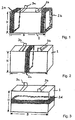
- the FIG. 1 1 shows an embodiment of an electrode plate stack 1 for installation in a cell vessel of a housing of a lead-acid battery.
- the electrode plate stack 1 is formed in a manner known per se from a multiplicity of separators, spaced apart from one another and located between adjacent electrode plates, one above the other and stacked one above the other.
- the separators may in this case be designed as pockets in a manner known per se, into which electrode plates are inserted.
- the electrode plate stack 1 is seen across the width B of the electrode plate stack 1 at the two outer edge regions each comprising a thermoplastic weldable band 2 a, 2 b made of polypropylene PP.
- the bands 2a, 2b are connected to one another at superimposed portions of a band 2a, 2b, for example, by ultrasonic welding, thermal welding or vibration welding.
- the ribbons 2a, 2b extend vertically above the height H of the electrode plate stack 1 from the bottom to the lid portion where the arresters 3a, 3b for the positive and negative electrode plates are respectively connected to the positive electrode plates and negative electrode plates and the corresponding ones Terminal poles are electrically connected.
- the bandaging (banding) of the electrode plate stacks 1 is carried out after stacking a number of interleaved electrode plate sets with alternating positive and negative electrode plates and intermediate separators in the form of pockets. Before or after bandaging then the sprue of the arresters 3a, 3b (connector).
- the electrode plate stacks 1 can be inserted into the cell vessel with minimum set play.
- the illustrated vertical bandages provide an insertion aid and the friction of the outer panels against the cell wall is minimized.
- the fact that the bandages are located at the outer edges of the electrode plates a pushing up of the outer plates during insertion of the electrode plate stack 1 is prevented in the cell vessel.
- the corners of the electrode plates can not be bent over.
- the bandages also have the advantage that the built-in electrode plate stack 1 is permanently under pressure. This reduces the risk of the positive mass being blown off and greatly improves the cycle capability of the lead-acid battery. In addition, the vibration resistance is significantly improved.
- thermoplastically weldable strips 2 as bandages for electrode plate stacks 1 also has the advantage, in particular in the case of AGM batteries with a fixed electrolyte, that it is possible to dispense with the use of a nonwoven material on the separator surface.
- the bandages also have the advantage that the complexity of separators can be reduced. With a bandage it is no longer necessary to adjust the game via the variation of the separator thickness.
- the walls of the cell vessels no longer have to be as thick as hitherto. Due to the stable walls, a stiffness must conventionally be achieved, so that a pressure acting on the walls compresses the electrode plates of an electrode plate stack.
- the bandage eliminates the need for sturdy walls and eliminates the need for glass fiber or talcum filled materials that have previously provided stability and cycle resistance.
- the bandages of the electrode plate stacks 1 also have the advantage that growth of positive electrode plates made of expanded metal meshes having no frame is effectively suppressed.
- FIG. 2 1 shows an embodiment of an electrode plate stack 1 in which a bandage with a thermoplastically weldable band 2c is provided vertically above the overall height H relative to the width B of the electrode plate stack 1 in the middle region.
- FIG. 3 shows another embodiment, in which a bandage of a thermoplastic weldable band 2d is provided in relation to the height H of the electrode plate stack 1 middle region, wherein the bandage extends horizontally across the width of the electrode plate stack 1.
- the illustrated bandages can be combined with each other as desired.
- the width of the thermoplastic tapes 2 should be in the range of about 20 mm to 30 mm.
- the tensile force of the bandages on the electrode plates of an electrode plate stack 1 can be variably adjusted as needed and should be selected so that it withstands the pressure of the electrode plate stack 1 in volume work.
- bands 2 made of polypropylene PP or similar acid-resistant thermoplastically weldable materials By using bands 2 made of polypropylene PP or similar acid-resistant thermoplastically weldable materials, a simple production of the bandage without risk of damaging the edges of the electrode plates is achieved.
- the bandage and the weld are long-term stable and withstand the thermal loads as well as the acid influences.
Landscapes
- Engineering & Computer Science (AREA)
- Manufacturing & Machinery (AREA)
- Chemical & Material Sciences (AREA)
- Chemical Kinetics & Catalysis (AREA)
- Electrochemistry (AREA)
- General Chemical & Material Sciences (AREA)
- Secondary Cells (AREA)
- Connection Of Batteries Or Terminals (AREA)
- Liquid Developers In Electrophotography (AREA)
- Supply Devices, Intensifiers, Converters, And Telemotors (AREA)
- Lubricants (AREA)
Description
- Die Erfindung betrifft einen Bleiakkumulator mit Plattenstapeln, die aus einer Vielzahl von mit zwischen benachbarten Elektroden liegenden Separatoren voneinander beabstandet übereinander gestapelten Elektrodenplatten gebildet sind.
- Herkömmliche Elektrodenplattenstapel werden aus einer Vielzahl in Separatoren eingetaschte Elektrodenplatten gebildet, die anschließend in ein Zellgefäß eingeführt werden. Die Weite des Zellgefäßes und damit das Spiel des Elektrodenplattenstapels im Zellgefäß wird herkömmlicherweise durch im Zellgefäß angespritzte Rippen bestimmt. Um das Einschieben eines Elektrodenplattenstapels in ein Zellgefäß zu erleichtern, wird herkömmlicherweise eine den Elektrodenplattenstapel teilweise umschließende Polypropylenfolie genutzt.
- Ein Problem bei Bleiakkumulatoren stellt zudem das Wachstum der positiven Gitterplatten dar. Dieses Wachstum tritt insbesondere bei Gitterplatten aus Streckmetall auf, da diese keine stabilisierenden Rahmen besitzen.
- Das Bandagieren von Elektrodenplattenstapeln mindestens an den Kanten ist bekannt. Die Bandagen können im Fertigungsprozess leicht um die sehr stabilen Elektrodenplatten herumgelegt und verklebt werden. Derartige Verfahren sind beispielsweise in der
EP 1 148 569 A2 beschrieben. Die verklebten Bandagen sind langzeitstabil, da sie auf den Elektrodenplatten prismatischer Batterien gut haften und der mechanische Aufbau der prismatischen Akkumulatoren eine Befestigung der Bandagen ohne Gefahr der Verformung der Elektrodenplatten erlaubt. - Aus der
JP 62-278771 A JP 58-018882 A - In dem
US-Patent 6,780,540 B2 ist ein mit Federelementen versehenes Gehäuse für Elektrodenplattenstapel beschrieben. Durch die Führungen wird der Elektrodenplattenstapel seitlich sicher gehalten. - Ausgehend hiervon ist es Aufgabe der vorliegenden Erfindung, einen verbesserten Akkumulator zu schaffen bei dem das Einführen eines Elektrodenplattenstapels erleichtert und die Betriebsfestigkeit erhöht wird.
- Die Aufgabe wird mit dem Akkumulator der eingangs genannten Art dadurch gelöst, dass ein Elektrodenplattenstapel mit mindestens einem den Elektrodenplattenstapel jeweils umfassenden thermoplastisch verschweißbaren Band zusammengehalten wird.
- Durch die Bandagierung der Elektrodenplattenstapel mit thermoplastisch verschweißbaren Bändern wird erreicht, dass die Elektrodenplattenstapel leicht in ein Zellgefäß einführbar sind und dauerhaft unter Druck stehen. Dadurch wird die Gefahr des Abschlammens der positiven Masse im Betrieb verringert und die Zyklenfähigkeit des Akkumulators stark verbessert. Auch die Rüttelfestigkeit wird verbessert.
- Die Endabschnitte der Bänder können nach dem Umschlagen um einen Elektrodenplattenstapel einfach verschweißt werden. Es hat sich gezeigt, dass durch die Verwendung thermoplastisch verschweißbarer Bänder sichergestellt wird, dass die leicht verformbaren Kanten der Elektrodenplatten, die z. B. bei Bleiakkumulatoren aus leicht verformbaren Bleimaterial bestehen, bei dem Prozess des Umschlagens und thermoplastischen Verschweißens geschont werden. Zudem ist keine Haftung der thermoplastischen Bänder an den Elektrodenplatten erforderlich, wie beim herkömmlichen Verkleben der Bandagen für prismatische Akkumulatoren.
- Durch die Nutzung thermoplastisch verschweißbarer Bänder und die thermoplastische Verschweißung der übereinander liegenden Abschnitte eines Bandes wird somit sichergestellt, dass bei dem Umschlagen und bei der Verschweißung der Bandagen die Kanten der leicht verformbaren Elektrodenplatten nicht beschädigt werden und die Verbindung der Bandageenden der Säure im Langzeitbetrieb standhält und auch den thermischen Bedingungen gewachsen ist.
- Daher sollten die thermoplastisch verschweißbaren Bänder sowie die Verschweißung säureresistent sein.
- Besonders vorteilhaft ist es, wenn die Bänder eine Breite im Bereich von 5 mm bis 50 mm und bevorzugt von 20 mm bis 30 mm haben. Es hat sich herausgestellt, dass in diesem Bereich die Gefahr der Beschädigung der Kanten der Elektrodenplatten bestmöglich verringert ist und zudem die Oberfläche der äußeren Elektroden im noch vertretbaren Maß verringert ist. Die gewählte Breite stellt somit einen bestmöglichen Kompromiss dar.
- In einer Ausführungsform erstrecken sich die Bänder an den Außenrandbereichen der Elektrodenplattenstapel vertikal über die Bauhöhe der Elektrodenplatten. Diese Ausführungsform hat den Vorteil, dass hierdurch Beschädigungen der Außenrandbereiche beim Einschieben der Elektrodenplattenstapel in das Zellgefäß eines Batteriekastens bestmöglich verhindert werden. Bei dieser Ausführungsform wird das Einführen des Elektrodenplattenstapels in ein Zellgefäß erheblich erleichtert.
- Eine andere Ausführungsform sieht vor, dass sich mindestens eines Band bezogen auf die Breite der Elektrodenplatten im mittleren Bereich der Elektrodenplattenstapels vertikal über die Bauhöhe der Elektrodenplattenstapels erstreckt. D. h., dass eine Bandage im mittleren Bereich vom Boden bis zum Deckel erstreckt. Diese Ausführungsform wirkt dem Wachstum der Elektrodenplatten im flexibelsten und damit kritischsten mittleren Bereich der Elektrodenplatten optimal entgegen. Zudem dient die Bandage aufgrund ihrer Ausrichtung als Einschubhilfe.
- Eine andere Ausführungsform sieht vor, dass sich mindestens ein Band bezogen auf die Bauhöhe des Elektrodenplattenstapels im mittleren Bereich des Elektrodenplattenstapels horizontal über die Breite des Elektrodenplattenstapels erstreckt. Bei dieser Ausführungsform wird der Elektrodenplattenstapel durch die Bandage unter einem relativ gleichmäßigen Druck gehalten.
- Die drei beschriebenen Ausführungsformen können einzeln oder in beliebiger Kombination miteinander eingesetzt werden.
- Besonders vorteilhaft ist, wenn die übereinander liegenden Abschnitte eines Bandes jeweils ultraschallverschweißt sind. Das Verschweißen von thermoplastischen Bändern mittels Ultraschallsonotrode ist aus der Verpackungstechnik hinreichend bekannt und in automatisierten Verfahren beherrschbar. Die Ultraschallverschweißung ist auch ausreichend stabil und säurefest. Alternativ ist auch eine thermische oder Vibrationsverschweißung denkbar.
- Besonders vorteilhaft ist es, wenn die Bänder aus Polypropylen (PP) Polyethylen (PE) oder Polyethylenterephthalat (PET) sind.
- Die Erfindung wird nachfolgend anhand von Ausführungsbeispielen mit den beigefügten Zeichnungen näher erläutert. Es zeigen:
- Figur 1 -
- perspektivische Ansicht eines Elektrodenplattenstapels mit thermoplastisch verschweißten Bändern an den Außenrandbereichen;
- Figur 2 -
- perspektivische Ansicht eines Elektrodenplattenstapels mit thermoplastisch verschweißtem Band im mittleren Bereich;
- Figur 3 -
- perspektivische Ansicht eines Elektrodenplattenstapels mit thermoplastisch verschweißtem Band im mittleren Bereich.
- Die
Figur 1 lässt eine Ausführungsform eines Elektrodenplattenstapels 1 zum Einbau in ein Zellgefäß eines Gehäuses eines Bleiakkumulators erkennen. Der Elektrodenplattenstapel 1 ist in an sich bekannter Weise aus einer Vielzahl von mit zwischen benachbarten Elektrodenplatten liegenden Separatoren voneinander beabstandet übereinander gestapelten Elektrodenplatten gebildet. - Die Separatoren können hierbei in an sich bekannter Weise als Taschen ausgebildet sein, in die Elektrodenplatten hineingelegt sind.
- Der Elektrodenplattenstapel 1 wird über die Breite B des Elektrodenplattenstapels 1 gesehen an den beiden Außenrandbereichen jeweils mit einem thermoplastisch verschweißbaren Band 2a, 2b aus Polypropylen PP umfasst. Die Bänder 2a, 2b sind an übereinander liegenden Abschnitten eines Bandes 2a, 2b jeweils thermoplastisch beispielsweise durch Ultraschallverschweißung, thermisches Verschweißen oder Vibrationsschweißen miteinander verbunden. Die Bänder 2a, 2b erstrecken sich vertikal über die Bauhöhe H des Elektrodenplattenstapels 1 vom Boden bis zum Deckelbereich, an dem sich die Ableiter 3a, 3b für die positiven und negativen Elektrodenplatten befinden, die jeweils mit den positiven Elektrodenplatten bzw. negativen Elektrodenplatten und den entsprechenden Anschlusspolen elektrisch verbunden sind.
- Das Bandagieren (Bandarolieren) der Elektrodenplattenstapel 1 erfolgt nach dem Übereinanderstapeln einer Anzahl getaschter Elektrodenplattensätze mit abwechselnd positiven und negativen Elektrodenplatten und zwischenliegenden Separatoren in Form von Taschen. Vor oder nach dem Bandagieren erfolgt dann der Anguss der Ableiter 3a, 3b (Verbinder).
- Durch die Bandagen können die Elektrodenplattenstapel 1 mit minimalem Satzspiel in das Zellgefäß eingeschoben werden. Durch die dargestellten vertikalen Bandagen steht eine Einschiebehilfe zur Verfügung und die Reibung der Außenplatten an der Zellwand wird minimiert. Dadurch, dass die Bandagen sich an den Außenkanten der Elektrodenplatten befinden, wird ein Hochschieben der Außenplatten beim Einschieben des Elektrodenplattenstapels 1 in das Zellgefäß verhindert. Die Ecken der Elektrodenplatten können zudem nicht mehr umgebogen werden.
- Die Bandagen haben zudem den Vorteil, dass der eingebaute Elektrodenplattenstapel 1 dauerhaft unter Druck steht. Hierdurch wird die Gefahr des Abschlammens der positiven Masse reduziert und die Zyklenfähigkeit des Bleiakkumulators stark verbessert. Zudem wird die Rüttelfestigkeit wesentlich verbessert.
- Die Nutzung der thermoplastisch verschweißbaren Bänder 2 als Bandagen für Elektrodenplattenstapel 1 hat zudem insbesondere bei AGM-Batterien mit festgelegtem Elektrolyt den Vorteil, dass auf den Einsatz eines Vliesmaterials auf der Separatorenoberfläche verzichtet werden kann.
- Aufgrund der Fixierung des Elektrodenplattenstapels 1 durch die Bandage kann zudem auf im Zellgefäß herkömmlich angespritzte Rippen verzichtet werden, so dass die Batteriekästen einfacher aufgebaut werden können.
- Die Bandagen haben zudem den Vorteil, dass die Komplexität bei Separatoren verringert werden kann. Bei einer Bandage ist es nicht mehr erforderlich, dass das Spiel über die Variation der Separatordicke einzustellen.
- Dadurch, dass die Elektrodenplattenstapel 1 durch die Bandagen unter Druck gehalten werden, müssen die Wände der Zellgefäße nicht mehr so dick sein, wie bislang. Durch die stabilen Wände muss herkömmlicherweise eine Steifigkeit erzielt werden, so dass ein über die Wände wirkender Druck die Elektrodenplatten eines Elektrodenplattenstapels zusammenpresst. Durch die Bandage entfällt das Erfordernis von stabilen Wänden und auch die Notwendigkeit des Einsatzes von mit Glasfasern oder Talkum gefüllten Materialien, die bislang für Stabilität und Zyklenfestigkeit sorgen.
- Die Bandagen der Elektrodenplattenstapel 1 haben zudem den Vorteil, dass Wachstum von positiven Elektrodenplatten aus Streckmetallgittern, die keinen Rahmen aufweisen, wirkungsvoll unterdrückt wird.
- Die
Figur 2 lässt eine Ausführungsform eines Elektrodenplattenstapels 1 erkennen, bei dem eine Bandage mit einem thermoplastisch verschweißbaren Band 2c bezogen auf die Breite B des Elektrodenplattenstapels 1 im mittleren Bereich vertikal über die Bauhöhe H vorgesehen ist. Hierdurch wird ein ausreichender Druck insbesondere im mittleren Bereich sichergestellt. - Die
Figur 3 lässt eine andere Ausführungsform erkennen, bei der eine Bandage aus einem thermoplastisch verschweißbaren Band 2d im bezogen auf die Bauhöhe H des Elektrodenplattenstapels 1 mittleren Bereich vorgesehen ist, wobei sich die Bandage horizontal über die Breite des Elektrodenplattenstapels 1 erstreckt. - Die dargestellten Bandagen können beliebig miteinander kombiniert werden. Die Breite der thermoplastischen Bänder 2 sollte im Bereich von etwa 20 mm bis 30 mm liegen. Die Zugkraft der Bandagen auf die Elektrodenplatten eines Elektrodenplattenstapels 1 lässt sich variabel nach Bedarf einstellen und sollte so gewählt werden, dass sie dem Druck des Elektrodenplattenstapels 1 bei Volumenarbeit standhält. Durch die Nutzung von Bändern 2 aus Polypropylen PP oder ähnlichen säurefesten thermoplastisch verschweißbaren Materialien wird eine einfache Herstellung der Bandage ohne Gefahr der Beschädigung der Kanten der Elektrodenplatten erreicht. Die Bandage und die Verschweißung sind langzeitstabil und halten den thermischen Belastungen sowie den Säureeinflüssen stand.
Claims (9)
- Akkumulator mit Elektrodenplattenstapeln (1), die aus einer Vielzahl von mit zwischen benachbarten Efektrodenplatten liegenden Separatoren voneinander beabstandet übereinander gestapelten Elektrodenplatten gebildet sind, wobei ein Elektrodenplattenstapel (1) mit mindestens einem den Elektrodenplattenstapel (1) jeweils umfassenden thermoplastisch verschweißbaren Band (2) zusammengehalten wird, dadurch gekennzeichnet, dass übereinanderliegende Abschnitte eines Bandes (2) thermoplastisch miteinander verschweißt sind.
- Akkumulator nach Anspruch 1, dadurch gekennzeichnet, dass die thermoplastisch verschweißbaren Bänder (2) und die Verschweißung säureresistent sind.
- Akkumulator nach einem der Ansprüche 1 oder 2, dadurch gekennzeichnet, dass die Bänder (2) eine Breite im Bereich von 5 mm bis 50 mm und bevorzugt von 20 mm bis 30 mm haben.
- Akkumulator nach einem der Ansprüche 1 bis 3, dadurch gekennzeichnet, dass Bänder (2) sich an den Außenrandbereichen der Elektrodenplattenstapel (1) vertikal über die Bauhöhe (H) der Elektrodenplatten erstrecken.
- Akkumulator nach einem der Ansprüche 1 bis 4, dadurch gekennzeichnet, dass sich mindestens ein Band (2) bezogen auf die Breite (B) der Elektrodenplatten im mittleren Bereich der Elektrodenplattenstapel (1) vertikal über die Bauhöhe der Elektrodenplattenstapel (1) erstreckt.
- Akkumulator nach einem der Ansprüche 1 bis 5, dadurch gekennzeichnet, dass sich mindestens ein Band (2) bezogen auf die Bauhöhe (H) der Elektrodenplatten im mittleren Bereich der Elektrodenplattenstapel (1) horizontal über die Bauhöhe der Elektrodenplattenstapel (1) erstreckt.
- Akkumulator nach einem der vorhergehenden Ansprüche, dadurch gekennzeichnet, dass die übereinander liegenden Abschnitte eines Bandes (2) jeweils ultraschallverschweißt, thermisch verschweißt oder vibrationsverschweißt sind.
- Akkumulator nach einem der vorhergehenden Ansprüche, dadurch gekennzeichnet, dass die Bänder (2) aus Polypropylen (PP), Polyethylen (PE) oder Polyethylenterephthalat (PET) sind.
- Akkumulator nach einem der vorhergehenden Ansprüche, dadurch gekennzeichnet, dass der Akkumulator ein Bleiakkumulator ist und die Elektrodenplatten aus einer Bleilegierung gebildet sind.
Priority Applications (1)
| Application Number | Priority Date | Filing Date | Title |
|---|---|---|---|
| PL07001855T PL1830429T3 (pl) | 2006-02-01 | 2007-01-29 | Akumulator ołowiowy |
Applications Claiming Priority (1)
| Application Number | Priority Date | Filing Date | Title |
|---|---|---|---|
| DE202006001509U DE202006001509U1 (de) | 2006-02-01 | 2006-02-01 | Bleiakkumulator |
Publications (2)
| Publication Number | Publication Date |
|---|---|
| EP1830429A1 EP1830429A1 (de) | 2007-09-05 |
| EP1830429B1 true EP1830429B1 (de) | 2009-04-08 |
Family
ID=36129639
Family Applications (1)
| Application Number | Title | Priority Date | Filing Date |
|---|---|---|---|
| EP07001855A Not-in-force EP1830429B1 (de) | 2006-02-01 | 2007-01-29 | Bleiakkumulator |
Country Status (5)
| Country | Link |
|---|---|
| EP (1) | EP1830429B1 (de) |
| AT (1) | ATE428192T1 (de) |
| DE (2) | DE202006001509U1 (de) |
| ES (1) | ES2321661T3 (de) |
| PL (1) | PL1830429T3 (de) |
Families Citing this family (2)
| Publication number | Priority date | Publication date | Assignee | Title |
|---|---|---|---|---|
| DE102007018609B4 (de) | 2007-04-18 | 2009-03-19 | Vb Autobatterie Gmbh & Co. Kgaa | Akkumulator und Verfahren zum Herstellen eines Akkumulators |
| DE202014003772U1 (de) | 2014-05-07 | 2014-06-13 | Xenia Kübler | Mobiles Toilettensystem |
Family Cites Families (4)
| Publication number | Priority date | Publication date | Assignee | Title |
|---|---|---|---|---|
| JPS63252363A (ja) * | 1987-02-13 | 1988-10-19 | Matsushita Electric Ind Co Ltd | 鉛蓄電池の製造法 |
| JPH0310830A (ja) * | 1989-05-25 | 1991-01-18 | Akzo Nv | ループ形成装置 |
| US6487833B1 (en) * | 2000-01-29 | 2002-12-03 | Howard W. Jaenson | Strap welding system and method |
| JP4712152B2 (ja) * | 2000-04-18 | 2011-06-29 | パナソニック株式会社 | 角形電池及びその製造方法 |
-
2006
- 2006-02-01 DE DE202006001509U patent/DE202006001509U1/de not_active Expired - Lifetime
-
2007
- 2007-01-29 ES ES07001855T patent/ES2321661T3/es active Active
- 2007-01-29 EP EP07001855A patent/EP1830429B1/de not_active Not-in-force
- 2007-01-29 PL PL07001855T patent/PL1830429T3/pl unknown
- 2007-01-29 DE DE502007000568T patent/DE502007000568D1/de active Active
- 2007-01-29 AT AT07001855T patent/ATE428192T1/de active
Also Published As
| Publication number | Publication date |
|---|---|
| DE502007000568D1 (de) | 2009-05-20 |
| ES2321661T3 (es) | 2009-06-09 |
| EP1830429A1 (de) | 2007-09-05 |
| DE202006001509U1 (de) | 2006-03-23 |
| PL1830429T3 (pl) | 2009-08-31 |
| ATE428192T1 (de) | 2009-04-15 |
Similar Documents
| Publication | Publication Date | Title |
|---|---|---|
| EP2885827B1 (de) | Verspannen von batteriezellen durch eine bombierte ausgestaltung des batteriegehäuses | |
| DE202022003318U1 (de) | Batterie und Batteriepack und Fahrzeug damit | |
| DE60130302T2 (de) | Vielfach gestapelte elektrochemische zelle und verfahren zu deren herstellung | |
| DE69927556T2 (de) | Flache Zellen | |
| DE10225041B4 (de) | Galvanisches Element | |
| US10115996B2 (en) | Stepped electrode assembly, secondary battery including the electrode assembly, and method of manufacturing the electrode assembly | |
| DE102012018128A1 (de) | Einzelzelle, Batterie und Verfahren zur Herstellung einer Einzelzelle | |
| DE69805031T2 (de) | Batterieseparator mit perforationsbeständigem Rand | |
| EP2389696A1 (de) | Galvanische zelle mit umhüllung ii | |
| DE102011015830A1 (de) | Elektrochemische Zelle zum Speichern elektrischer Energie | |
| DE102010050040A1 (de) | Anordnung eines Elektrodenstapels einer elektrochemischen Energiespeichereinrichtung | |
| EP0250846A2 (de) | Bahnmaterial und daraus hergestellte Separatorentaschen für die Elektrodenplatten von Akkumulatoren | |
| EP1830429B1 (de) | Bleiakkumulator | |
| DE112012002605T5 (de) | Batterie | |
| WO2009074279A2 (de) | Stromableiter für eine galvanische zelle | |
| DE102013020863A1 (de) | Rahmenelement, Zellblock, Batterie sowie Verfahren zur Herstellung eines Rahmenelements | |
| DE102023117650A1 (de) | Zellgehäuse zur Aufnahme eines Batteriezellkörpers oder einer Batteriezelle | |
| DE2454824A1 (de) | Separator fuer einen elektrischen akkumulator | |
| DE102011110814A1 (de) | Energiespeichervorrichtung und Verfahren zur Herstellung einer Energiespeichervorrichtung | |
| CH636989A5 (de) | Mehrzelliger bleiakkumulator. | |
| DE102010050992A1 (de) | Zellenverbund für eine Batterie | |
| DE3045479C2 (de) | ||
| WO2000008704A1 (en) | Wound lead acid battery with non-circular cells | |
| DE4206075A1 (de) | Alkalische und elektrochemische batterie | |
| EP2137786B1 (de) | Akkumulator und verfahren zum herstellen eines akkumulators |
Legal Events
| Date | Code | Title | Description |
|---|---|---|---|
| PUAI | Public reference made under article 153(3) epc to a published international application that has entered the european phase |
Free format text: ORIGINAL CODE: 0009012 |
|
| AK | Designated contracting states |
Kind code of ref document: A1 Designated state(s): AT BE BG CH CY CZ DE DK EE ES FI FR GB GR HU IE IS IT LI LT LU LV MC NL PL PT RO SE SI SK TR |
|
| AX | Request for extension of the european patent |
Extension state: AL BA HR MK YU |
|
| 17P | Request for examination filed |
Effective date: 20080229 |
|
| 17Q | First examination report despatched |
Effective date: 20080407 |
|
| AKX | Designation fees paid |
Designated state(s): AT BE BG CH CY CZ DE DK EE ES FI FR GB GR HU IE IS IT LI LT LU LV MC NL PL PT RO SE SI SK TR |
|
| GRAP | Despatch of communication of intention to grant a patent |
Free format text: ORIGINAL CODE: EPIDOSNIGR1 |
|
| GRAS | Grant fee paid |
Free format text: ORIGINAL CODE: EPIDOSNIGR3 |
|
| GRAA | (expected) grant |
Free format text: ORIGINAL CODE: 0009210 |
|
| AK | Designated contracting states |
Kind code of ref document: B1 Designated state(s): AT BE BG CH CY CZ DE DK EE ES FI FR GB GR HU IE IS IT LI LT LU LV MC NL PL PT RO SE SI SK TR |
|
| REG | Reference to a national code |
Ref country code: GB Ref legal event code: FG4D Free format text: NOT ENGLISH |
|
| REG | Reference to a national code |
Ref country code: CH Ref legal event code: EP |
|
| REG | Reference to a national code |
Ref country code: IE Ref legal event code: FG4D |
|
| REF | Corresponds to: |
Ref document number: 502007000568 Country of ref document: DE Date of ref document: 20090520 Kind code of ref document: P |
|
| REG | Reference to a national code |
Ref country code: ES Ref legal event code: FG2A Ref document number: 2321661 Country of ref document: ES Kind code of ref document: T3 |
|
| PG25 | Lapsed in a contracting state [announced via postgrant information from national office to epo] |
Ref country code: SI Free format text: LAPSE BECAUSE OF FAILURE TO SUBMIT A TRANSLATION OF THE DESCRIPTION OR TO PAY THE FEE WITHIN THE PRESCRIBED TIME-LIMIT Effective date: 20090408 |
|
| REG | Reference to a national code |
Ref country code: PL Ref legal event code: T3 |
|
| NLV1 | Nl: lapsed or annulled due to failure to fulfill the requirements of art. 29p and 29m of the patents act | ||
| REG | Reference to a national code |
Ref country code: IE Ref legal event code: FD4D |
|
| PG25 | Lapsed in a contracting state [announced via postgrant information from national office to epo] |
Ref country code: PT Free format text: LAPSE BECAUSE OF FAILURE TO SUBMIT A TRANSLATION OF THE DESCRIPTION OR TO PAY THE FEE WITHIN THE PRESCRIBED TIME-LIMIT Effective date: 20090908 Ref country code: LT Free format text: LAPSE BECAUSE OF FAILURE TO SUBMIT A TRANSLATION OF THE DESCRIPTION OR TO PAY THE FEE WITHIN THE PRESCRIBED TIME-LIMIT Effective date: 20090408 Ref country code: FI Free format text: LAPSE BECAUSE OF FAILURE TO SUBMIT A TRANSLATION OF THE DESCRIPTION OR TO PAY THE FEE WITHIN THE PRESCRIBED TIME-LIMIT Effective date: 20090408 |
|
| PG25 | Lapsed in a contracting state [announced via postgrant information from national office to epo] |
Ref country code: SE Free format text: LAPSE BECAUSE OF FAILURE TO SUBMIT A TRANSLATION OF THE DESCRIPTION OR TO PAY THE FEE WITHIN THE PRESCRIBED TIME-LIMIT Effective date: 20090708 Ref country code: NL Free format text: LAPSE BECAUSE OF FAILURE TO SUBMIT A TRANSLATION OF THE DESCRIPTION OR TO PAY THE FEE WITHIN THE PRESCRIBED TIME-LIMIT Effective date: 20090408 Ref country code: IS Free format text: LAPSE BECAUSE OF FAILURE TO SUBMIT A TRANSLATION OF THE DESCRIPTION OR TO PAY THE FEE WITHIN THE PRESCRIBED TIME-LIMIT Effective date: 20090808 Ref country code: LV Free format text: LAPSE BECAUSE OF FAILURE TO SUBMIT A TRANSLATION OF THE DESCRIPTION OR TO PAY THE FEE WITHIN THE PRESCRIBED TIME-LIMIT Effective date: 20090408 |
|
| PG25 | Lapsed in a contracting state [announced via postgrant information from national office to epo] |
Ref country code: DK Free format text: LAPSE BECAUSE OF FAILURE TO SUBMIT A TRANSLATION OF THE DESCRIPTION OR TO PAY THE FEE WITHIN THE PRESCRIBED TIME-LIMIT Effective date: 20090408 Ref country code: RO Free format text: LAPSE BECAUSE OF FAILURE TO SUBMIT A TRANSLATION OF THE DESCRIPTION OR TO PAY THE FEE WITHIN THE PRESCRIBED TIME-LIMIT Effective date: 20090408 Ref country code: IE Free format text: LAPSE BECAUSE OF FAILURE TO SUBMIT A TRANSLATION OF THE DESCRIPTION OR TO PAY THE FEE WITHIN THE PRESCRIBED TIME-LIMIT Effective date: 20090408 Ref country code: CZ Free format text: LAPSE BECAUSE OF FAILURE TO SUBMIT A TRANSLATION OF THE DESCRIPTION OR TO PAY THE FEE WITHIN THE PRESCRIBED TIME-LIMIT Effective date: 20090408 Ref country code: EE Free format text: LAPSE BECAUSE OF FAILURE TO SUBMIT A TRANSLATION OF THE DESCRIPTION OR TO PAY THE FEE WITHIN THE PRESCRIBED TIME-LIMIT Effective date: 20090408 |
|
| PLBE | No opposition filed within time limit |
Free format text: ORIGINAL CODE: 0009261 |
|
| STAA | Information on the status of an ep patent application or granted ep patent |
Free format text: STATUS: NO OPPOSITION FILED WITHIN TIME LIMIT |
|
| PG25 | Lapsed in a contracting state [announced via postgrant information from national office to epo] |
Ref country code: SK Free format text: LAPSE BECAUSE OF FAILURE TO SUBMIT A TRANSLATION OF THE DESCRIPTION OR TO PAY THE FEE WITHIN THE PRESCRIBED TIME-LIMIT Effective date: 20090408 |
|
| 26N | No opposition filed |
Effective date: 20100111 |
|
| PG25 | Lapsed in a contracting state [announced via postgrant information from national office to epo] |
Ref country code: BG Free format text: LAPSE BECAUSE OF FAILURE TO SUBMIT A TRANSLATION OF THE DESCRIPTION OR TO PAY THE FEE WITHIN THE PRESCRIBED TIME-LIMIT Effective date: 20090708 |
|
| BERE | Be: lapsed |
Owner name: VB AUTOBATTERIE G.M.B.H. & CO. KGAA Effective date: 20100131 |
|
| PG25 | Lapsed in a contracting state [announced via postgrant information from national office to epo] |
Ref country code: MC Free format text: LAPSE BECAUSE OF NON-PAYMENT OF DUE FEES Effective date: 20100131 |
|
| PG25 | Lapsed in a contracting state [announced via postgrant information from national office to epo] |
Ref country code: GR Free format text: LAPSE BECAUSE OF FAILURE TO SUBMIT A TRANSLATION OF THE DESCRIPTION OR TO PAY THE FEE WITHIN THE PRESCRIBED TIME-LIMIT Effective date: 20090709 |
|
| PG25 | Lapsed in a contracting state [announced via postgrant information from national office to epo] |
Ref country code: BE Free format text: LAPSE BECAUSE OF NON-PAYMENT OF DUE FEES Effective date: 20100131 |
|
| PGRI | Patent reinstated in contracting state [announced from national office to epo] |
Ref country code: IT Effective date: 20110501 |
|
| REG | Reference to a national code |
Ref country code: CH Ref legal event code: PL |
|
| GBPC | Gb: european patent ceased through non-payment of renewal fee |
Effective date: 20110129 |
|
| PG25 | Lapsed in a contracting state [announced via postgrant information from national office to epo] |
Ref country code: LI Free format text: LAPSE BECAUSE OF NON-PAYMENT OF DUE FEES Effective date: 20110131 Ref country code: CH Free format text: LAPSE BECAUSE OF NON-PAYMENT OF DUE FEES Effective date: 20110131 |
|
| PG25 | Lapsed in a contracting state [announced via postgrant information from national office to epo] |
Ref country code: GB Free format text: LAPSE BECAUSE OF NON-PAYMENT OF DUE FEES Effective date: 20110129 |
|
| PG25 | Lapsed in a contracting state [announced via postgrant information from national office to epo] |
Ref country code: CY Free format text: LAPSE BECAUSE OF FAILURE TO SUBMIT A TRANSLATION OF THE DESCRIPTION OR TO PAY THE FEE WITHIN THE PRESCRIBED TIME-LIMIT Effective date: 20090408 |
|
| PG25 | Lapsed in a contracting state [announced via postgrant information from national office to epo] |
Ref country code: HU Free format text: LAPSE BECAUSE OF FAILURE TO SUBMIT A TRANSLATION OF THE DESCRIPTION OR TO PAY THE FEE WITHIN THE PRESCRIBED TIME-LIMIT Effective date: 20091009 Ref country code: LU Free format text: LAPSE BECAUSE OF NON-PAYMENT OF DUE FEES Effective date: 20100129 |
|
| PG25 | Lapsed in a contracting state [announced via postgrant information from national office to epo] |
Ref country code: TR Free format text: LAPSE BECAUSE OF FAILURE TO SUBMIT A TRANSLATION OF THE DESCRIPTION OR TO PAY THE FEE WITHIN THE PRESCRIBED TIME-LIMIT Effective date: 20090408 |
|
| PGFP | Annual fee paid to national office [announced via postgrant information from national office to epo] |
Ref country code: PL Payment date: 20140103 Year of fee payment: 8 Ref country code: ES Payment date: 20140127 Year of fee payment: 8 Ref country code: FR Payment date: 20140117 Year of fee payment: 8 Ref country code: AT Payment date: 20140102 Year of fee payment: 8 Ref country code: IT Payment date: 20140122 Year of fee payment: 8 |
|
| REG | Reference to a national code |
Ref country code: DE Ref legal event code: R082 Ref document number: 502007000568 Country of ref document: DE Representative=s name: MEISSNER, BOLTE & PARTNER GBR, DE Ref country code: DE Ref legal event code: R082 Ref document number: 502007000568 Country of ref document: DE Representative=s name: MEISSNER BOLTE PATENTANWAELTE RECHTSANWAELTE P, DE |
|
| REG | Reference to a national code |
Ref country code: AT Ref legal event code: MM01 Ref document number: 428192 Country of ref document: AT Kind code of ref document: T Effective date: 20150129 |
|
| REG | Reference to a national code |
Ref country code: FR Ref legal event code: ST Effective date: 20150930 |
|
| PG25 | Lapsed in a contracting state [announced via postgrant information from national office to epo] |
Ref country code: FR Free format text: LAPSE BECAUSE OF NON-PAYMENT OF DUE FEES Effective date: 20150202 Ref country code: AT Free format text: LAPSE BECAUSE OF NON-PAYMENT OF DUE FEES Effective date: 20150129 |
|
| PG25 | Lapsed in a contracting state [announced via postgrant information from national office to epo] |
Ref country code: IT Free format text: LAPSE BECAUSE OF NON-PAYMENT OF DUE FEES Effective date: 20150129 |
|
| REG | Reference to a national code |
Ref country code: ES Ref legal event code: FD2A Effective date: 20160226 |
|
| PG25 | Lapsed in a contracting state [announced via postgrant information from national office to epo] |
Ref country code: ES Free format text: LAPSE BECAUSE OF NON-PAYMENT OF DUE FEES Effective date: 20150130 |
|
| PG25 | Lapsed in a contracting state [announced via postgrant information from national office to epo] |
Ref country code: PL Free format text: LAPSE BECAUSE OF NON-PAYMENT OF DUE FEES Effective date: 20150129 |
|
| REG | Reference to a national code |
Ref country code: DE Ref legal event code: R082 Ref document number: 502007000568 Country of ref document: DE Representative=s name: MEISSNER BOLTE PATENTANWAELTE RECHTSANWAELTE P, DE |
|
| REG | Reference to a national code |
Ref country code: DE Ref legal event code: R082 Ref document number: 502007000568 Country of ref document: DE Representative=s name: MEISSNER BOLTE PATENTANWAELTE RECHTSANWAELTE P, DE Ref country code: DE Ref legal event code: R081 Ref document number: 502007000568 Country of ref document: DE Owner name: CLARIOS GERMANY GMBH & CO. KGAA, DE Free format text: FORMER OWNER: VB AUTOBATTERIE GMBH & CO. KGAA, 30419 HANNOVER, DE |
|
| PGFP | Annual fee paid to national office [announced via postgrant information from national office to epo] |
Ref country code: DE Payment date: 20210127 Year of fee payment: 15 |
|
| REG | Reference to a national code |
Ref country code: DE Ref legal event code: R119 Ref document number: 502007000568 Country of ref document: DE |
|
| PG25 | Lapsed in a contracting state [announced via postgrant information from national office to epo] |
Ref country code: DE Free format text: LAPSE BECAUSE OF NON-PAYMENT OF DUE FEES Effective date: 20220802 |
|
| P01 | Opt-out of the competence of the unified patent court (upc) registered |
Free format text: CASE NUMBER: APP_836/2025 Effective date: 20250108 |