EP1830150A1 - Heat exchanger - Google Patents
Heat exchanger Download PDFInfo
- Publication number
- EP1830150A1 EP1830150A1 EP05809378A EP05809378A EP1830150A1 EP 1830150 A1 EP1830150 A1 EP 1830150A1 EP 05809378 A EP05809378 A EP 05809378A EP 05809378 A EP05809378 A EP 05809378A EP 1830150 A1 EP1830150 A1 EP 1830150A1
- Authority
- EP
- European Patent Office
- Prior art keywords
- fin
- rib
- insertion holes
- outer edge
- heat exchanger
- Prior art date
- Legal status (The legal status is an assumption and is not a legal conclusion. Google has not performed a legal analysis and makes no representation as to the accuracy of the status listed.)
- Withdrawn
Links
Images



Classifications
-
- F—MECHANICAL ENGINEERING; LIGHTING; HEATING; WEAPONS; BLASTING
- F28—HEAT EXCHANGE IN GENERAL
- F28F—DETAILS OF HEAT-EXCHANGE AND HEAT-TRANSFER APPARATUS, OF GENERAL APPLICATION
- F28F1/00—Tubular elements; Assemblies of tubular elements
- F28F1/10—Tubular elements and assemblies thereof with means for increasing heat-transfer area, e.g. with fins, with projections, with recesses
- F28F1/12—Tubular elements and assemblies thereof with means for increasing heat-transfer area, e.g. with fins, with projections, with recesses the means being only outside the tubular element
- F28F1/24—Tubular elements and assemblies thereof with means for increasing heat-transfer area, e.g. with fins, with projections, with recesses the means being only outside the tubular element and extending transversely
- F28F1/32—Tubular elements and assemblies thereof with means for increasing heat-transfer area, e.g. with fins, with projections, with recesses the means being only outside the tubular element and extending transversely the means having portions engaging further tubular elements
-
- F—MECHANICAL ENGINEERING; LIGHTING; HEATING; WEAPONS; BLASTING
- F24—HEATING; RANGES; VENTILATING
- F24F—AIR-CONDITIONING; AIR-HUMIDIFICATION; VENTILATION; USE OF AIR CURRENTS FOR SCREENING
- F24F1/00—Room units for air-conditioning, e.g. separate or self-contained units or units receiving primary air from a central station
- F24F1/0007—Indoor units, e.g. fan coil units
- F24F1/0059—Indoor units, e.g. fan coil units characterised by heat exchangers
- F24F1/0067—Indoor units, e.g. fan coil units characterised by heat exchangers by the shape of the heat exchangers or of parts thereof, e.g. of their fins
Definitions
- the present invention relates to a heat exchanger. More particularly, the invention relates to a heat exchanger suitable for use in air conditioners.
- This heat exchanger includes fins and pipes.
- the fins are each formed from a plate in a rectangular shape.
- the fins are placed at intervals.
- the fins each have a plurality of insertion holes formed for insertion of the pipes therethrough.
- the insertion holes are provided in a staggered arrangement in the fins.
- a plurality of protruding threads in an approximately linear shape are formed.
- the plurality of protruding threads are generally parallel to each other. The protruding threads extend in directions different from the longitudinal direction of the fin.
- the pipes are placed such that they perpendicularly intersect with each fin. More specifically, the pipes are inserted in the insertion holes of the fin in the state of extending in the normal direction to the surface of the fin.
- the rigidity of the fin is improved by forming the protruding threads between the insertion holes in the fin. This prevents parts near the insertion holes in the fin from being deformed when the pipes are inserted in the insertion holes.
- the conventional heat exchanger has a difficulty in increasing rigidity of the fin even with formation of protruding threads when the size of the insertion holes is large, when the minimum distance value between the adjoining insertion holes is small, and/or when the width of the fin is small.
- An object of the present invention is to provide a heat exchanger capable of increasing the rigidity of a fin and preventing deterioration of heat exchanging efficiency.
- the present invention provides a heat exchanger, comprising:
- center of the rib refers to the center in the width direction of the rib.
- the first rib is formed so as to extend generally parallel to the outer edge of the fin, so that the strength of the fin is increased effectively.
- the insertion holes for insertion of the heat transfer tubes are placed in one row or in staggered arrangement in the fin, more heat transfer tubes can be placed without decreasing the strength of the fin.
- the present invention because 0.4 ⁇ La holds, it is possible to prevent the center of the rib from becoming too close to the outer edge of the fin and therefore deformation of the edge portion and/or the first rib of the fin can be avoided. Also, because La ⁇ (L-D/2-0.5) holds, it is possible to prevent the center of the first rib becoming close to the insertion holes enough to cause deformation of the first rib.
- the rib having a size larger than a predetermined size is formed on the fin having strength larger than a predetermined strength. This makes it possible to certainly reinforce the fin having strength larger than the predetermined strength with the rib having a high reinforcement effect. Therefore, the strength of the fin is brought to a satisfactory level, and fin deflection and fin tilting are certainly prevented from occurring during an operation of stacking the fins.
- the rib is not excessively large. This prevents the rib from becoming resistance against a heat transfer medium, thereby preventing generation of turbulent flow and the like in a flow of the heat transfer medium. Therefore, the flow of the heat transfer medium can be smoothed and the decrease in heat exchanging efficiency, which would otherwise be caused by change of the heat transfer medium due to the formation of the rib, is certainly prevented.
- t ⁇ 0.15 holds so that the thickness of the fin is not too large. This makes it possible to increase the stacking or packing density of fins and to thereby achieve excellent heat exchange efficiency. Also, production costs of the fin can be reduced.
- the insertion holes are placed in staggered arrangement in the fin, the insertion holes placed on one side of the fin is generally parallel to the outer edge, a second rib extending generally parallel to the outer edge is formed on the fin between the insertion holes which are adjacent to each other in a direction generally perpendicular to a direction in which the outer edge extends, and when a width of the second rib is set as LL2 [mm] and a height of the second rib is set as h2 [mm], then 0.15 ⁇ LL ⁇ 2 ⁇ 0.5 , and 0.5 ⁇ t ⁇ h ⁇ 2 ⁇ 2.5 ⁇ t .
- the second rib is formed in the fin between the insertion holes that are adjacent to each other in the above approximately perpendicular direction, so that the strength near the center of the fin is increased and thereby the strength of the fin can be further increased.
- the first rib is formed so as to extend generally parallel to the outer edge of the fin, so that the strength of the fin is increased effectively.
- the insertion holes for insertion of the heat transfer tubes are placed in one row or in staggered arrangement in the fin, more heat transfer tubes can be placed without decreasing the strength of the fin.
- the present invention 0.4 ⁇ La ⁇ (L-D/2-0.5), 0.15 ⁇ LL1, 0.05 ⁇ t, 0.5t ⁇ h1, D ⁇ 7.5, 15 ⁇ P, and D/P ⁇ 0.5 hold, it is possible to certainly reinforce a fin having strength larger than a predetermined strength with the rib having a high reinforcement effect. Therefore, the strength of the fin is brought to a satisfactory level, and fin deflection and fin tilting is certainly prevented from occurring during stacking of fins.
- the rib is not excessively large. This prevents the rib from becoming resistance against a heat transfer medium, thereby preventing generation of turbulence and the like in a flow of the heat transfer medium. Therefore, the flow of the heat transfer medium can be smoothed and the decrease in heat exchanging efficiency, which would otherwise be caused by change of the heat transfer medium, is certainly prevented.
- the second rib is formed between the adjacent rows of the insertion holes in the fin, so that the strength of a part near the center of the fin is increased and thereby the strength of the fin can be further increased.
- Fig. 1 is a schematic cross sectional view showing an air conditioner using a heat exchanger in the first embodiment of the present invention.
- reference numeral 1 denotes a blower fan
- 2 denotes a heat exchanger.
- arrow a shows a vertically upward direction in the state where the heat exchanger is placed in the air conditioner in use
- arrow b shows a flow direction of air as a heat transfer medium.
- a casing in which the blower fan 1 and the heat exchanger 2 are housed is omitted for simplicity's sake.
- This air conditioner is designed such that the blower fan 1 is rotated to blow out air, which was sucked in via the heat exchanger 2, through an unshown blowoff opening.
- the heat exchanger 2 includes fins 6 and heat transfer tubes (unshown).
- the fins 6 are provided so as to be disposed at specified intervals in a direction perpendicular to the drawing sheet of Fig. 1.
- Each fin 6 is in a flat plate shape.
- the fin 6 has a configuration which is bent like an upset V-letter so that its upper part in the vertical direction shown in Fig. 1 by arrow a forms a protruding section.
- the fin 6 has an outer edge inclined with respect to the vertical direction, and also has a first section 8 and a second section 9 which form the bent part, and a third section 10 which links to a lower part in the vertical direction of the second section 9.
- the first section 8 is located downstream of the flow of air from the second section 9.
- the third section 10 extends in a generally vertical direction.
- the first section 8, the second section 9, and the third section 10 have an elongate, rectangular-shaped cross section.
- a first rib 15 extending generally in parallel with the longitudinal direction of the second section 9 is formed on a longitudinal edge portion on the leeward of the second section 9.
- the fin 6 has a rectangular-shaped section, with the first rib 15 extending generally in parallel with an outer edge of the longitudinal direction of the rectangular-shaped section.
- Each heat transfer tube extends in a direction in which the fins 6 are arranged or arrayed, i.e., in the direction normal to the surface of the plate-shaped fin 5 (a direction perpendicular to the drawing sheet of Fig. 1).
- the heat transfer tubes are inserted through the fins 6 which are arrayed at specified intervals.
- the heat transfer tubes are provided in two rows in staggered arrangement.
- the insertion holes are arranged in two rows in the width direction and in 16 rows in the longitudinal direction, while in the second section 9, the insertion holes are arranged in two rows in the width direction and twelve rows in the longitudinal direction. In the third section 10, the insertion holes are arranged in two rows in the width direction and in eight rows in the longitudinal direction.
- Each of the two rows arranged in the width direction of the insertion holes in the first section 8 is generally parallel to the longitudinal outer edge of the first section 8, while each of the two rows arranged in the width direction of the insertion holes in the second section 9 is generally parallel to the longitudinal outer edge of the second section 9.
- Each of the two rows arranged in the width direction of the insertion holes in the third section 10 is generally parallel to the longitudinal outer edge of the third section 10.
- This heat exchanger performs heat exchange between the fluid flowing through the heat transfer tubes and the air running over the heat transfer tube.
- Figs. 2A and 2B are views showing the second section 9 of the fin 6 in detail. More specifically, Fig. 2A is a partial enlarged view showing the second section 9 of the fin 6. Fig. 2B is a part of the cross sectional view of Fig. 2A taken along an ⁇ - ⁇ line.
- reference numeral 15 denotes a first rib and reference numeral 22 denotes an insertion hole for insertion of the heat transfer tube formed in the fin 6.
- arrow b shows a flow of air.
- Fig. 2A only the inside diameter of the insertion hole 22 is shown and the detailed aperture shape of the insertion hole is omitted for simplicity's sake.
- the rib 15 extends generally in parallel with an outer edge 25 of the plate-shaped fin 6.
- the plate-shaped fin 6 has insertion holes 22 for insertion of a plurality of heat transfer tubes. Moreover, the first rib 15 is placed closer to the outer edge 25 than all the insertion holes 22 are.
- the insertion hole 22 is formed such that the following equations (2) to (4) are satisfied: D ⁇ 7.5 , 15 ⁇ P D / P ⁇ 0.5
- the fin 6 and the first rib 15 are set so as to satisfy the following equations (5) to (7). 0.15 ⁇ LL ⁇ 1 ⁇ 0.5 0.05 ⁇ t ⁇ 0.15 0.5 ⁇ t ⁇ h ⁇ 1 ⁇ 2.5 ⁇ t
- the first rib 15 is formed so as to extend along the outer edge 25 of the fin 6 (generally parallel to the outer edge 25 of the fin 6), so that the strength of the fin 6 is increased effectively.
- the heat transfer tubes are placed in staggered arrangement through the fin 6, so that an increased number of heat transfer tubes can be placed without decreasing the strength of the fin 6.
- the heat exchanger in the first embodiment 0.15 ⁇ LL1, 0.05 ⁇ t, 0.5t ⁇ hl, D ⁇ 7.5, 15 ⁇ P, and D/P ⁇ 0.5 hold, and the first rib 15 having a size larger than a predetermined size is formed on the fin 6 having strength larger than a predetermined strength.
- LL1 ⁇ 0.5 and h1 ⁇ 2.5t holds, which conditions prevent the first rib 15 from becoming too large. This in turn prevents the first rib 15 from becoming resistance against air flow, thereby preventing generation of turbulent flow and the like in the air flow. Therefore, the air flow can be smoothed and the decrease in heat exchanging efficiency, which would otherwise be caused by change of the air flow due to the formation of the first rib 15, is certainly prevented.
- t ⁇ 0.15 holds so that the thickness of the fin 6 is not too large. This makes it possible to increase the stacking or packing density of the fins 6 and to achieve excellent heat exchange efficiency.
- the first rib 15 is formed in such a manner that it projects from one surface 27 of the plate-shaped fin 6 so as to satisfy the equations (1) to (7).
- a plurality of first ribs that satisfy the equations (1) to (7) may be formed so that they project from one surface of the plate-shaped fin.
- a plurality of first ribs that satisfy the equations (1) to (7) may also be formed so as to project from both the surfaces (e.g., surface 27 and surface 28 in Fig. 2B) of the plate-shaped fin.
- one first rib 15 generally parallel to the outer edge 25 is formed only on the leeward side in the width direction of the second section 9.
- a plurality of ribs may be formed so as to satisfy the equation (1) to (7).
- first ribs generally parallel to the outer edge on the leeward side in the width direction of the second section, but also to provide one or more first ribs generally parallel to the outer edge of the first section on the windward side in the width direction of the first section, while providing one or more first ribs generally parallel to the outer edge of the first section on the leeward side in the width direction of the first section and providing one or more first ribs generally parallel to the outer edge of the third section on the leeward side in the width direction of the third section.
- the heat exchanger in this invention may be structured so that heat transfer tubes are arranged in one row, i.e., one per the width of the fin, or in three or more rows in staggered arrangement in the width direction of the fin at least in a part of the fin and that one or more first ribs which satisfy the equations (1) to (7) are formed at least in a part of the longitudinal edge portion of the fin.
- holes for insertion of heat transfer tubes may be placed in one row in a fin 30, while at an longitudinal edge portion of the fin 30 on the downstream side of the flow of air shown by arrow c, one first rib 32 generally parallel to an outer edge of the edge portion may be formed.
- holes for insertion of heat transfer tubes may be placed in one row, i.e., one hole per the width, in a fin 40, while at a longitudinal edge portion of the fin 40 on the upstream side of the flow of air shown by arrow d, one first rib 42 generally parallel to an outer edge of the edge portion may be formed.
- Fig. 3A holes for insertion of heat transfer tubes may be placed in one row in a fin 30, while at an longitudinal edge portion of the fin 30 on the downstream side of the flow of air shown by arrow c, one first rib 32 generally parallel to an outer edge of the edge portion may be formed.
- holes for insertion of heat transfer tubes may be placed in one row, i.e., one hole per the width, in a fin 40, while at
- holes for insertion of heat transfer tubes may be placed in one row in a fin 50, while at longitudinal edge portions of the fin 50 on the upstream side and the downstream side of the flow of air shown by arrow e, first ribs 52 and 53 generally parallel to outer edges of those edge portions may be formed, respectively.
- holes for insertion of heat transfer tubes may be placed in two rows in staggered arrangement in the width direction of a fin 60, while at longitudinal edge portions of the fin 60 on both the upstream side and the downstream side of the flow of air shown by an arrow f, first ribs 62, 63 generally parallel to outer edges of those edge portions may be formed, respectively.
- the first rib 15 is formed in almost the entire edge portion on the leeward of the second section 9. According to this invention, however, the first rib may be provided only in a part of the edge portion such that the first rib extends generally parallel to the part of the outer edge of the fin. For example, the first rib may be provided only in a part of the edge portion on the leeward of the second section so as to extend generally parallel to the outer edge of that part of the edge portion.
- the fin 6 is composed of the first section 8 and second section 9 which form a bend section, and the third section 10.
- the fin on which the first rib is formed may take any shape, without being limited to the shape described in this embodiment, for example, the fin may be composed of one plate having a flat or circular-arc shaped cross section.
- a groove 29 having a trapezoidal cross section is formed on the back side of the area where the first rib 15 is formed.
- grooves other than the groove having a trapezoidal cross section such as grooves having a V-shaped section or a U-shaped section, may be formed on the back side of the area where the first rib is formed. It is not imperative to form the groove on the back side of the area where the first rib is formed.
- the first rib may be formed in all of the plurality of fins.
- the first rib may be formed only in one or more of the plurality of fins and there may be fins without the first rib.
- Fig. 4 is a partial enlarged view showing a second section 79 of a fin 73 included in a heat exchanger of a second embodiment.
- the heat exchanger of the second embodiment is different from the heat exchanger of the first embodiment only in that a second rib 76 being generally parallel to the first rib 75 and having the shape generally identical to the first rib 75 is formed between the rows of insertion holes 72 placed in staggered arrangement in the width direction in the second section 79 for receiving the heat transfer tubes.
- the insertion holes 72 for insertion of heat transfer tubes are placed in two rows and in staggered arrangement in width direction in the second section 79 of the fin 73.
- Each row of the insertion holes 72 provided totally in staggered arrangement in width direction is generally parallel to a longitudinal outer edge 77 of the second section 79 and to the first rib 75.
- the second rib 76 is formed between the rows of the insertion holes 72 in the second section 79 in the state generally parallel to the outer edge 77 and the first rib 75.
- the second rib 76 is formed between the rows of the insertion holes 72 in the second section 79 of the fin 73, so that the strength of a central area of the second section 79 of the fin 73 is increased, by which the strength of the fin 73 is increased further.
- the insertion holes 72 are arranged in two rows and in staggered arrangement in the width direction of the second section 79 and the second rib 76 is formed between the two rows juxtaposed in the width direction.
- the insertion holes for insertion of heat transfer tubes may be arranged in two or more rows juxtaposed in the width direction in at least a part of the fin, and two or more second ribs may be formed between a given row and a row adjacent to the row in the width direction.
- the insertion holes for insertion of heat transfer tubes may also be arranged in three or more rows in at least a part of the fin, and one or more second ribs may be placed between two or more different rows.
- the second rib 76 being generally parallel to the first rib 75 and having the shape generally identical to the first rib 75 is formed between the rows of the insertion holes 72.
- a second rib which is generally parallel to the first rib and which satisfies equations obtained by rewriting the equations (5) and (7) [herein, the equations obtained by rewriting the equations (5) and (7) refer to the equations obtained by rewriting the width LL1 [mm] of the first rib 15 as the width LL2 [mm] of the second rib 76, and the height h1 [mm] of the first rib 15 as the height h2 [mm] of the second rib 76 in the equations (5) and (7)], may be formed between the rows of the insertion holes for insertion of heat transfer tubes.
- heat exchanger of this invention is applied to air conditioners in the first and the second embodiments, it should be understood that the heat exchanger of this invention can be applied to devices other than the air conditioners, such as the refrigerators.
Landscapes
- Engineering & Computer Science (AREA)
- Physics & Mathematics (AREA)
- Thermal Sciences (AREA)
- Mechanical Engineering (AREA)
- General Engineering & Computer Science (AREA)
- Chemical & Material Sciences (AREA)
- Combustion & Propulsion (AREA)
- Geometry (AREA)
- Heat-Exchange Devices With Radiators And Conduit Assemblies (AREA)
Abstract
A fin (6) is provided with a rib (15) extending generally parallel to an outer edge (25) of the fin (6) and insertion holes (22) placed in staggered arrangement for receiving heat exchange tubes. The insertion holes (22) and the rib (15) are formed such that when an inside diameter of the insertion holes (22) is set as D [mm], a distance between a center of the insertion hole (22) and the outer edge (25) is set as L [mm], a distance between a center of the rib (15) and the outer edge (25) is set as La [mm], a width of the rib (15) is set as LL1 [mm], a thickness of the fin (6) is set as t [mm], a height of the rib (15) is set as h1 [mm], and a minimum distance between the insertion holes is set as P [mm], then 0.4 < La < (L-D/2-0.5), 0.15 < LL1 < 0.5, 0.05 < t < 0.15, 0.5t < h1 < 2.5t, D < 7.5, P > 15, and D/P < 0.5.
Description
- The present invention relates to a heat exchanger. More particularly, the invention relates to a heat exchanger suitable for use in air conditioners.
- Conventionally, there has been a heat exchanger disclosed in
JP 2-309195 A - This heat exchanger includes fins and pipes. The fins are each formed from a plate in a rectangular shape. The fins are placed at intervals. The fins each have a plurality of insertion holes formed for insertion of the pipes therethrough. The insertion holes are provided in a staggered arrangement in the fins. Between the insertion holes provided in a staggered arrangement in each fin, a plurality of protruding threads in an approximately linear shape are formed. The plurality of protruding threads are generally parallel to each other. The protruding threads extend in directions different from the longitudinal direction of the fin.
- The pipes are placed such that they perpendicularly intersect with each fin. More specifically, the pipes are inserted in the insertion holes of the fin in the state of extending in the normal direction to the surface of the fin.
- In the conventional heat exchanger, the rigidity of the fin is improved by forming the protruding threads between the insertion holes in the fin. This prevents parts near the insertion holes in the fin from being deformed when the pipes are inserted in the insertion holes.
- However, in the conventional heat exchanger, since the protruding threads extend in a direction different from the longitudinal direction of the fin, it is impossible to achieve sufficient reinforcement concerning the longitudinal direction of the fin, which has largest influence on the strength of the fin, thereby causing a problem of an insufficiently reinforced fin.
- Moreover, the conventional heat exchanger has a difficulty in increasing rigidity of the fin even with formation of protruding threads when the size of the insertion holes is large, when the minimum distance value between the adjoining insertion holes is small, and/or when the width of the fin is small.
- Moreover in the conventional heat exchanger, when the height of the protruding thread provided on the fin is large, it interferes with the flow of air passing outside of the pipe, which causes the heat exchanger to have a decreased heat exchanging efficiency.
- An object of the present invention is to provide a heat exchanger capable of increasing the rigidity of a fin and preventing deterioration of heat exchanging efficiency.
- In order to attain the object, the present invention provides a heat exchanger, comprising:
- a plurality of heat transfer tubes; and
- at least one plate-shaped fin having a first rib generally parallel to an outer edge of the fin and having insertion holes for receiving the heat transfer tubes,
- It is to be noted that the center of the rib refers to the center in the width direction of the rib.
- According to the present invention, the first rib is formed so as to extend generally parallel to the outer edge of the fin, so that the strength of the fin is increased effectively.
- According to the present invention, since the insertion holes for insertion of the heat transfer tubes are placed in one row or in staggered arrangement in the fin, more heat transfer tubes can be placed without decreasing the strength of the fin.
- According to the present invention, because 0.4<La holds, it is possible to prevent the center of the rib from becoming too close to the outer edge of the fin and therefore deformation of the edge portion and/or the first rib of the fin can be avoided. Also, because La<(L-D/2-0.5) holds, it is possible to prevent the center of the first rib becoming close to the insertion holes enough to cause deformation of the first rib.
- According to the present invention, 0.15<LL1, 0.05<t, 0.5t<h1, D<7.5, 15<P, and D/P<0.5 hold, and the rib having a size larger than a predetermined size is formed on the fin having strength larger than a predetermined strength. This makes it possible to certainly reinforce the fin having strength larger than the predetermined strength with the rib having a high reinforcement effect. Therefore, the strength of the fin is brought to a satisfactory level, and fin deflection and fin tilting are certainly prevented from occurring during an operation of stacking the fins.
- According to the present invention, because LL1<0.5 and h1<2.5t hold, the rib is not excessively large. This prevents the rib from becoming resistance against a heat transfer medium, thereby preventing generation of turbulent flow and the like in a flow of the heat transfer medium. Therefore, the flow of the heat transfer medium can be smoothed and the decrease in heat exchanging efficiency, which would otherwise be caused by change of the heat transfer medium due to the formation of the rib, is certainly prevented.
- Also, according to the present invention, t<0.15 holds so that the thickness of the fin is not too large. This makes it possible to increase the stacking or packing density of fins and to thereby achieve excellent heat exchange efficiency. Also, production costs of the fin can be reduced.
- In one embodiment, the insertion holes are placed in staggered arrangement in the fin,
the insertion holes placed on one side of the fin is generally parallel to the outer edge,
a second rib extending generally parallel to the outer edge is formed on the fin between the insertion holes which are adjacent to each other in a direction generally perpendicular to a direction in which the outer edge extends, and
when a width of the second rib is set as LL2 [mm] and a height of the second rib is set as h2 [mm], then

- According to the embodiment, the second rib is formed in the fin between the insertion holes that are adjacent to each other in the above approximately perpendicular direction, so that the strength near the center of the fin is increased and thereby the strength of the fin can be further increased.
- According to the embodiment, 0.15 < LL2 < 0.5 and 0.5t < h2 < 2.5t, so that reinforcement of the fin is ensured while the flow of a heat transfer medium is smoothed.
- According to the present invention, the first rib is formed so as to extend generally parallel to the outer edge of the fin, so that the strength of the fin is increased effectively.
- According to the present invention, since the insertion holes for insertion of the heat transfer tubes are placed in one row or in staggered arrangement in the fin, more heat transfer tubes can be placed without decreasing the strength of the fin.
- According to the present invention, 0.4<La<(L-D/2-0.5), 0.15<LL1, 0.05<t, 0.5t<h1, D<7.5, 15<P, and D/P<0.5 hold, it is possible to certainly reinforce a fin having strength larger than a predetermined strength with the rib having a high reinforcement effect. Therefore, the strength of the fin is brought to a satisfactory level, and fin deflection and fin tilting is certainly prevented from occurring during stacking of fins.
- According to the present invention, because LL1<0.5 and h1<2.5t hold, the rib is not excessively large. This prevents the rib from becoming resistance against a heat transfer medium, thereby preventing generation of turbulence and the like in a flow of the heat transfer medium. Therefore, the flow of the heat transfer medium can be smoothed and the decrease in heat exchanging efficiency, which would otherwise be caused by change of the heat transfer medium, is certainly prevented.
- Also, according to the present invention, because of t<0.15, it is possible to increase the stacking ability of fins and to thereby achieve excellent heat exchange efficiency.
- According to the present invention, the second rib is formed between the adjacent rows of the insertion holes in the fin, so that the strength of a part near the center of the fin is increased and thereby the strength of the fin can be further increased.
- The present invention will become more fully understood from the detailed description given hereinbelow and the accompanying drawings which are given by way of illustration only, and thus are not intended to limit the present invention, and wherein:
- Fig. 1 is a schematic cross sectional view showing an air conditioner having a heat exchanger in a first embodiment of the present invention;
- Fig. 2A is a detailed view showing a part of a fin included in the heat exchanger of the first embodiment;
- Fig. 2B is a detailed view showing a part of a fin included in the heat exchanger of the first embodiment;
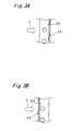
- Fig. 3A is a view showing an example of the first rib formed on the fin;
- Fig. 3B is a view showing an example of the first rib formed on the fin;
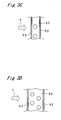
- Fig. 3C is a view showing an example of the first rib formed on the fin;
- Fig. 3D is a view showing an example of the first rib formed on the fin; and
- Fig. 4 is a partial enlarged view showing a fin of a heat exchanger in a second embodiment of the present invention.
- The present invention will be described in detail below based on the embodiments shown in the figures.
- Fig. 1 is a schematic cross sectional view showing an air conditioner using a heat exchanger in the first embodiment of the present invention. In Fig. 1,
reference numeral 1 denotes a blower fan, and 2 denotes a heat exchanger. In Fig. 1, arrow a shows a vertically upward direction in the state where the heat exchanger is placed in the air conditioner in use, and arrow b shows a flow direction of air as a heat transfer medium. In Fig. 1, a casing in which theblower fan 1 and theheat exchanger 2 are housed is omitted for simplicity's sake. - This air conditioner is designed such that the
blower fan 1 is rotated to blow out air, which was sucked in via theheat exchanger 2, through an unshown blowoff opening. - The
heat exchanger 2 includesfins 6 and heat transfer tubes (unshown). Thefins 6 are provided so as to be disposed at specified intervals in a direction perpendicular to the drawing sheet of Fig. 1. Eachfin 6 is in a flat plate shape. Thefin 6 has a configuration which is bent like an upset V-letter so that its upper part in the vertical direction shown in Fig. 1 by arrow a forms a protruding section. - The
fin 6 has an outer edge inclined with respect to the vertical direction, and also has afirst section 8 and asecond section 9 which form the bent part, and athird section 10 which links to a lower part in the vertical direction of thesecond section 9. As shown in Fig. 1, thefirst section 8 is located downstream of the flow of air from thesecond section 9. Thethird section 10 extends in a generally vertical direction. Thefirst section 8, thesecond section 9, and thethird section 10 have an elongate, rectangular-shaped cross section. - A
first rib 15 extending generally in parallel with the longitudinal direction of thesecond section 9 is formed on a longitudinal edge portion on the leeward of thesecond section 9. Thus, in the first embodiment, thefin 6 has a rectangular-shaped section, with thefirst rib 15 extending generally in parallel with an outer edge of the longitudinal direction of the rectangular-shaped section. - There are arranged a plurality of heat transfer tubes. Each heat transfer tube extends in a direction in which the
fins 6 are arranged or arrayed, i.e., in the direction normal to the surface of the plate-shaped fin 5 (a direction perpendicular to the drawing sheet of Fig. 1). The heat transfer tubes are inserted through thefins 6 which are arrayed at specified intervals. As shown in Fig. 1, in each of thefirst section 8, thesecond section 9, and thethird section 10, the heat transfer tubes are provided in two rows in staggered arrangement. - More specifically, in the
first section 8, the insertion holes are arranged in two rows in the width direction and in 16 rows in the longitudinal direction, while in thesecond section 9, the insertion holes are arranged in two rows in the width direction and twelve rows in the longitudinal direction. In thethird section 10, the insertion holes are arranged in two rows in the width direction and in eight rows in the longitudinal direction. - Each of the two rows arranged in the width direction of the insertion holes in the
first section 8 is generally parallel to the longitudinal outer edge of thefirst section 8, while each of the two rows arranged in the width direction of the insertion holes in thesecond section 9 is generally parallel to the longitudinal outer edge of thesecond section 9. Each of the two rows arranged in the width direction of the insertion holes in thethird section 10 is generally parallel to the longitudinal outer edge of thethird section 10. - Fluid runs through the heat transfer tubes. This heat exchanger performs heat exchange between the fluid flowing through the heat transfer tubes and the air running over the heat transfer tube.
- Figs. 2A and 2B are views showing the
second section 9 of thefin 6 in detail. More specifically, Fig. 2A is a partial enlarged view showing thesecond section 9 of thefin 6. Fig. 2B is a part of the cross sectional view of Fig. 2A taken along an α-α line. - In Fig. 2A and Fig. 2B,
reference numeral 15 denotes a first rib andreference numeral 22 denotes an insertion hole for insertion of the heat transfer tube formed in thefin 6. In Fig. 2A, arrow b shows a flow of air. In Fig. 2A, only the inside diameter of theinsertion hole 22 is shown and the detailed aperture shape of the insertion hole is omitted for simplicity's sake. - The
rib 15 extends generally in parallel with anouter edge 25 of the plate-shapedfin 6. The plate-shapedfin 6 has insertion holes 22 for insertion of a plurality of heat transfer tubes. Moreover, thefirst rib 15 is placed closer to theouter edge 25 than all the insertion holes 22 are. - In the first embodiment, as shown in Fig. 2A and Fig. 2B, when the inside diameter of the
insertion hole 22 is set as D [mm], a distance between the center of theinsertion hole 22 nearest to therib 15 and theouter edge 25 is set as L [mm], and a distance between the center of therib 15 and theouter edge 25 is set as La [mm], then La is designed to satisfy the following equation (1):
- As shown in Fig. 2A, when a minimum value of the distance between the insertion holes 22 adjacent to each other is set as P [mm], the
insertion hole 22 is formed such that the following equations (2) to (4) are satisfied:


- As shown in Fig. 2B, when the width of the
first rib 15 is set as LL1 [mm], the thickness of thefin 6 is set as t [mm] and the height of thefirst rib 15 is set as h1 [mm], then thefin 6 and thefirst rib 15 are set so as to satisfy the following equations (5) to (7).


- According to the heat exchanger in the first embodiment, the
first rib 15 is formed so as to extend along theouter edge 25 of the fin 6 (generally parallel to theouter edge 25 of the fin 6), so that the strength of thefin 6 is increased effectively. - According to the heat exchanger in the first embodiment, the heat transfer tubes are placed in staggered arrangement through the
fin 6, so that an increased number of heat transfer tubes can be placed without decreasing the strength of thefin 6. - According to the heat exchanger in the first embodiment, 0.4<La holds, which prevents the center of the
first rib 15 from becoming too close to the outer edge of thefin 6 and thus avoids deformation of the edge portion and/or thefirst rib 15 of thefin 6. Also, because La<(L-D/2-0.5) holds, the center of thefirst rib 2 is prevented from becoming too close to the insertion holes 22 and thus deformation of thefirst rib 15 is avoided. - According to the heat exchanger in the first embodiment, 0.15<LL1, 0.05<t, 0.5t<hl, D<7.5, 15<P, and D/P<0.5 hold, and the
first rib 15 having a size larger than a predetermined size is formed on thefin 6 having strength larger than a predetermined strength. This makes it possible to certainly reinforce thefin 6 having strength larger than a predetermined strength with thefirst rib 15 having a high reinforcement effect. Therefore, the strength of thefin 6 is brought to a satisfactory level, and fin deflection and fin tilting are certainly prevented from occurring during a stacking operation of thefins 6. - According to the heat exchanger in the first embodiment, LL1<0.5 and h1<2.5t holds, which conditions prevent the
first rib 15 from becoming too large. This in turn prevents thefirst rib 15 from becoming resistance against air flow, thereby preventing generation of turbulent flow and the like in the air flow. Therefore, the air flow can be smoothed and the decrease in heat exchanging efficiency, which would otherwise be caused by change of the air flow due to the formation of thefirst rib 15, is certainly prevented. - According to the heat exchanger in the first embodiment, t<0.15 holds so that the thickness of the
fin 6 is not too large. This makes it possible to increase the stacking or packing density of thefins 6 and to achieve excellent heat exchange efficiency. - In the heat exchanger in the first embodiment, as shown in Fig. 2B, the
first rib 15 is formed in such a manner that it projects from onesurface 27 of the plate-shapedfin 6 so as to satisfy the equations (1) to (7). However, in this invention, a plurality of first ribs that satisfy the equations (1) to (7) may be formed so that they project from one surface of the plate-shaped fin. A plurality of first ribs that satisfy the equations (1) to (7) may also be formed so as to project from both the surfaces (e.g.,surface 27 andsurface 28 in Fig. 2B) of the plate-shaped fin. - In the heat exchanger of the first embodiment, one
first rib 15 generally parallel to theouter edge 25 is formed only on the leeward side in the width direction of thesecond section 9. However, in this invention, a plurality of ribs may be formed so as to satisfy the equation (1) to (7). For example, it is acceptable not only to provide one or more first ribs generally parallel to the outer edge on the leeward side in the width direction of the second section, but also to provide one or more first ribs generally parallel to the outer edge of the first section on the windward side in the width direction of the first section, while providing one or more first ribs generally parallel to the outer edge of the first section on the leeward side in the width direction of the first section and providing one or more first ribs generally parallel to the outer edge of the third section on the leeward side in the width direction of the third section. - Although in the heat exchanger of the first embodiment, the heat transfer tubes are placed in two rows in staggered arrangement in the width direction of the
second section 9 and one first rib is formed on the leeward side of thesecond section 9, the heat exchanger in this invention may be structured so that heat transfer tubes are arranged in one row, i.e., one per the width of the fin, or in three or more rows in staggered arrangement in the width direction of the fin at least in a part of the fin and that one or more first ribs which satisfy the equations (1) to (7) are formed at least in a part of the longitudinal edge portion of the fin. - For example, as shown in Fig. 3A, holes for insertion of heat transfer tubes may be placed in one row in a
fin 30, while at an longitudinal edge portion of thefin 30 on the downstream side of the flow of air shown by arrow c, onefirst rib 32 generally parallel to an outer edge of the edge portion may be formed. Also, as shown in Fig. 3B, holes for insertion of heat transfer tubes may be placed in one row, i.e., one hole per the width, in afin 40, while at a longitudinal edge portion of thefin 40 on the upstream side of the flow of air shown by arrow d, onefirst rib 42 generally parallel to an outer edge of the edge portion may be formed. Also, as shown in Fig. 3C, holes for insertion of heat transfer tubes may be placed in one row in afin 50, while at longitudinal edge portions of thefin 50 on the upstream side and the downstream side of the flow of air shown by arrow e,first ribs fin 60, while at longitudinal edge portions of thefin 60 on both the upstream side and the downstream side of the flow of air shown by an arrow f,first ribs 62, 63 generally parallel to outer edges of those edge portions may be formed, respectively. - In the heat exchanger of the embodiment, the
first rib 15 is formed in almost the entire edge portion on the leeward of thesecond section 9. According to this invention, however, the first rib may be provided only in a part of the edge portion such that the first rib extends generally parallel to the part of the outer edge of the fin. For example, the first rib may be provided only in a part of the edge portion on the leeward of the second section so as to extend generally parallel to the outer edge of that part of the edge portion. - In the heat exchanger of the first embodiment, the
fin 6 is composed of thefirst section 8 andsecond section 9 which form a bend section, and thethird section 10. However, according to this invention, the fin on which the first rib is formed may take any shape, without being limited to the shape described in this embodiment, for example, the fin may be composed of one plate having a flat or circular-arc shaped cross section. - In the heat exchanger of the first embodiment, as shown in Fig. 2B, a
groove 29 having a trapezoidal cross section is formed on the back side of the area where thefirst rib 15 is formed. In this invention, however, grooves other than the groove having a trapezoidal cross section, such as grooves having a V-shaped section or a U-shaped section, may be formed on the back side of the area where the first rib is formed. It is not imperative to form the groove on the back side of the area where the first rib is formed. - Moreover in the heat exchanger of this invention, the first rib may be formed in all of the plurality of fins. The first rib may be formed only in one or more of the plurality of fins and there may be fins without the first rib.
- Fig. 4 is a partial enlarged view showing a
second section 79 of afin 73 included in a heat exchanger of a second embodiment. The heat exchanger of the second embodiment is different from the heat exchanger of the first embodiment only in that asecond rib 76 being generally parallel to thefirst rib 75 and having the shape generally identical to thefirst rib 75 is formed between the rows of insertion holes 72 placed in staggered arrangement in the width direction in thesecond section 79 for receiving the heat transfer tubes. - In the heat exchanger of the second embodiment, description of the component parts identical to those in the heat exchanger of the first embodiment will be omitted. In the heat exchanger of the second embodiment, description of operation, effects and modifications similar or identical to those of the heat exchanger in the first embodiment will be omitted, and only the structure, operation, effects and modifications different from those of the heat exchanger in the first embodiment will be explained.
- As shown in Fig. 4, the insertion holes 72 for insertion of heat transfer tubes are placed in two rows and in staggered arrangement in width direction in the
second section 79 of thefin 73. Each row of the insertion holes 72 provided totally in staggered arrangement in width direction is generally parallel to a longitudinalouter edge 77 of thesecond section 79 and to thefirst rib 75. Thesecond rib 76 is formed between the rows of the insertion holes 72 in thesecond section 79 in the state generally parallel to theouter edge 77 and thefirst rib 75. - In the heat exchanger of the second embodiment, the
second rib 76 is formed between the rows of the insertion holes 72 in thesecond section 79 of thefin 73, so that the strength of a central area of thesecond section 79 of thefin 73 is increased, by which the strength of thefin 73 is increased further. - In the heat exchanger of the second embodiment, the insertion holes 72 are arranged in two rows and in staggered arrangement in the width direction of the
second section 79 and thesecond rib 76 is formed between the two rows juxtaposed in the width direction. However, in this invention, the insertion holes for insertion of heat transfer tubes may be arranged in two or more rows juxtaposed in the width direction in at least a part of the fin, and two or more second ribs may be formed between a given row and a row adjacent to the row in the width direction. The insertion holes for insertion of heat transfer tubes may also be arranged in three or more rows in at least a part of the fin, and one or more second ribs may be placed between two or more different rows. - Moreover, in the heat exchanger of the second embodiment, the
second rib 76 being generally parallel to thefirst rib 75 and having the shape generally identical to thefirst rib 75 is formed between the rows of the insertion holes 72. In this invention, a second rib, which is generally parallel to the first rib and which satisfies equations obtained by rewriting the equations (5) and (7) [herein, the equations obtained by rewriting the equations (5) and (7) refer to the equations obtained by rewriting the width LL1 [mm] of thefirst rib 15 as the width LL2 [mm] of thesecond rib 76, and the height h1 [mm] of thefirst rib 15 as the height h2 [mm] of thesecond rib 76 in the equations (5) and (7)], may be formed between the rows of the insertion holes for insertion of heat transfer tubes. - Although the heat exchanger of this invention is applied to air conditioners in the first and the second embodiments, it should be understood that the heat exchanger of this invention can be applied to devices other than the air conditioners, such as the refrigerators.
- Embodiments of the invention being thus described, it will be obvious that the same may be varied in many ways. Such variations are not to be regarded as a departure from the spirit and scope of the invention, and all such modifications as would be obvious to one skilled in the art are intended to be included within the scope of the following claims.
wherein the insertion holes are placed in one row or in staggered arrangement in the fin, and
wherein when an inside diameter of the insertion holes is set as D [mm], a distance between a center of the insertion hole nearest to the first rib and the outer edge is set as L [mm], a distance between a center of the first rib and the outer edge is set as La [mm], a width of the first rib is set as LL1 [mm], a thickness of the fin is set as t [mm], a height of the first rib is set as h1 [mm], and a minimum value of distance between the insertion holes adjacent to each other is set as P [mm], then


Claims (2)
- A heat exchanger, comprising:a plurality of heat transfer tubes; andat least one plate-shaped fin (6, 73) having a first rib (15, 75) generally parallel to an outer edge (25, 77) of the fin and having insertion holes (22, 72) for receiving the heat transfer tubes,wherein the first rib (15, 75) is placed closer to the outer edge (25, 77) than all the insertion holes (22, 72) are,wherein the insertion holes (22, 72) are placed in one row or in staggered arrangement in the fin (6, 73), andwherein when an inside diameter of the insertion holes (22, 72) is set as D [mm], a distance between a center of the insertion hole (22, 72) nearest to the first rib (15, 75) and the outer edge (25, 77) is set as L [mm], a distance between a center of the first rib (15, 75) and the outer edge (25, 77) is set as La [mm], a width of the first rib (15, 75) is set as LL1 [mm], a thickness of the fin (6, 73) is set as t [mm], a height of the first rib (15, 75) is set as h1 [mm], and a minimum value of distance between the insertion holes (22, 72) adjacent to each other is set as P [mm], then



- The heat exchanger according to claim 1, wherein
the insertion holes (72) are placed in staggered arrangement in the fin (73),
the insertion holes (72) placed on one side of the fin is generally parallel to the outer edge (77),
a second rib (76) extending generally parallel to the outer edge (77) is formed on the fin (73) between the insertion holes (72) which are adjacent to each other in a direction generally perpendicular to a direction in which the outer edge (77) extends, and
when a width of the second rib (76) is set as LL2 [mm] and a height of the second rib (76) is set as h2 [mm], then

Applications Claiming Priority (2)
| Application Number | Priority Date | Filing Date | Title |
|---|---|---|---|
| JP2004340321A JP2006153290A (en) | 2004-11-25 | 2004-11-25 | Heat exchanger |
| PCT/JP2005/021422 WO2006057235A1 (en) | 2004-11-25 | 2005-11-22 | Heat exchanger |
Publications (1)
| Publication Number | Publication Date |
|---|---|
| EP1830150A1 true EP1830150A1 (en) | 2007-09-05 |
Family
ID=36497972
Family Applications (1)
| Application Number | Title | Priority Date | Filing Date |
|---|---|---|---|
| EP05809378A Withdrawn EP1830150A1 (en) | 2004-11-25 | 2005-11-22 | Heat exchanger |
Country Status (6)
| Country | Link |
|---|---|
| US (1) | US20080060797A1 (en) |
| EP (1) | EP1830150A1 (en) |
| JP (1) | JP2006153290A (en) |
| CN (1) | CN101065636B (en) |
| AU (1) | AU2005308186B2 (en) |
| WO (1) | WO2006057235A1 (en) |
Cited By (1)
| Publication number | Priority date | Publication date | Assignee | Title |
|---|---|---|---|---|
| EP2107201A2 (en) | 2008-04-04 | 2009-10-07 | Eurofinestra S.r.l. | Production process of an eco modular window |
Families Citing this family (5)
| Publication number | Priority date | Publication date | Assignee | Title |
|---|---|---|---|---|
| JP5077926B2 (en) * | 2007-01-25 | 2012-11-21 | 国立大学法人 東京大学 | Heat exchanger |
| JP5409544B2 (en) * | 2010-08-04 | 2014-02-05 | 三菱電機株式会社 | Air conditioner indoor unit and air conditioner |
| JP5554741B2 (en) * | 2010-09-28 | 2014-07-23 | 日立アプライアンス株式会社 | Finned tube heat exchanger and air conditioner equipped with the same |
| CN105806125A (en) * | 2016-05-26 | 2016-07-27 | 珠海格力电器股份有限公司 | Fin and air conditioner heat exchanger |
| WO2018078800A1 (en) * | 2016-10-28 | 2018-05-03 | 三菱電機株式会社 | Heat exchanger and refrigeration cycle device |
Family Cites Families (21)
| Publication number | Priority date | Publication date | Assignee | Title |
|---|---|---|---|---|
| US1853487A (en) * | 1931-01-31 | 1932-04-12 | Fred M Young | Radiator construction |
| US2268361A (en) * | 1941-08-11 | 1941-12-30 | Fedders Mfg Co Inc | Heat exchange apparatus |
| US2545561A (en) * | 1947-09-26 | 1951-03-20 | Modine Mfg Co | Heating element for convection heaters |
| US2602650A (en) * | 1951-04-12 | 1952-07-08 | Marcotte Louis Philippe | Fin type radiator |
| US2994123A (en) * | 1956-06-14 | 1961-08-01 | Richard W Kritzer | Method of forming heat transfer units |
| US4173998A (en) * | 1978-02-16 | 1979-11-13 | Carrier Corporation | Formed coil assembly |
| JPS54156269U (en) * | 1978-04-24 | 1979-10-30 | ||
| JPS5523699A (en) * | 1979-08-06 | 1980-02-20 | Toshiba Corp | Crystal oscillator |
| JPS58158497A (en) * | 1982-03-17 | 1983-09-20 | Matsushita Electric Ind Co Ltd | Finned-tube type heat exchanger |
| JPH02309195A (en) | 1989-05-23 | 1990-12-25 | Sanyo Electric Co Ltd | Heat exchanger and manufacture thereof |
| JPH0590173U (en) * | 1992-04-20 | 1993-12-07 | 住友軽金属工業株式会社 | Fin tube heat exchanger |
| JP3312986B2 (en) * | 1994-02-25 | 2002-08-12 | 東芝キヤリア株式会社 | Heat exchanger and method of manufacturing heat exchanger |
| JPH09113068A (en) * | 1995-10-18 | 1997-05-02 | Sanyo Electric Co Ltd | Heat exchanger and air conditioner with heat exchanger |
| DE19544224B4 (en) * | 1995-11-28 | 2004-10-14 | Alstom | Chemical operation of a water / steam cycle |
| JPH10166088A (en) * | 1996-12-12 | 1998-06-23 | Mitsubishi Heavy Ind Ltd | Plate fin tube type heat exchanger |
| JP3762068B2 (en) * | 1997-10-24 | 2006-03-29 | 東芝キヤリア株式会社 | Heat exchanger and air conditioner |
| JP2000193389A (en) * | 1998-12-28 | 2000-07-14 | Hitachi Ltd | Outdoor unit of air conditioner |
| JP2001133178A (en) * | 1999-10-29 | 2001-05-18 | Matsushita Refrig Co Ltd | Heat exchanger |
| JP2001227889A (en) * | 2000-02-17 | 2001-08-24 | Hidaka Seiki Kk | Fin for heat exchanger |
| JP3883880B2 (en) * | 2002-02-22 | 2007-02-21 | 東芝キヤリア株式会社 | Heat exchanger |
| JP2003269881A (en) * | 2002-03-15 | 2003-09-25 | Toshiba Kyaria Kk | Fin tube type heat exchanger |
-
2004
- 2004-11-25 JP JP2004340321A patent/JP2006153290A/en active Pending
-
2005
- 2005-11-22 AU AU2005308186A patent/AU2005308186B2/en not_active Ceased
- 2005-11-22 CN CN2005800403340A patent/CN101065636B/en not_active Expired - Fee Related
- 2005-11-22 US US11/791,538 patent/US20080060797A1/en not_active Abandoned
- 2005-11-22 WO PCT/JP2005/021422 patent/WO2006057235A1/en not_active Ceased
- 2005-11-22 EP EP05809378A patent/EP1830150A1/en not_active Withdrawn
Non-Patent Citations (1)
| Title |
|---|
| See references of WO2006057235A1 * |
Cited By (1)
| Publication number | Priority date | Publication date | Assignee | Title |
|---|---|---|---|---|
| EP2107201A2 (en) | 2008-04-04 | 2009-10-07 | Eurofinestra S.r.l. | Production process of an eco modular window |
Also Published As
| Publication number | Publication date |
|---|---|
| US20080060797A1 (en) | 2008-03-13 |
| CN101065636A (en) | 2007-10-31 |
| CN101065636B (en) | 2010-12-01 |
| AU2005308186A1 (en) | 2006-06-01 |
| JP2006153290A (en) | 2006-06-15 |
| WO2006057235A1 (en) | 2006-06-01 |
| AU2005308186B2 (en) | 2009-05-28 |
Similar Documents
| Publication | Publication Date | Title |
|---|---|---|
| US11454448B2 (en) | Enhanced heat transfer surface | |
| EP2770290B1 (en) | Exhaust gas heat exchanger | |
| US7261147B2 (en) | Heat exchanger | |
| EP2447659A2 (en) | Heat exchanger and fin for the same | |
| EP1811254A2 (en) | Microchannel, flat tube exchanger with bent tube configuration | |
| EP2141435A1 (en) | Plate fin tube-type heat exchanger | |
| US20090173477A1 (en) | Heat exchanger fin | |
| CN103063076A (en) | Heat exchanger | |
| CN101592421A (en) | Fin tube heat exchanger | |
| EP2314973A1 (en) | Fin-tube heat exchanger | |
| WO2021018126A1 (en) | Heat exchanger and heat exchange system | |
| EP3415827B1 (en) | Air conditioner | |
| US6786276B2 (en) | Heat exchanger tube with optimized plates | |
| CN102563980A (en) | Heat exchanger | |
| US20080060797A1 (en) | Heat Exchanger | |
| CN110030865B (en) | Fin and heat exchanger with same | |
| CN101208575A (en) | Finned tube heat exchanger | |
| JP5138408B2 (en) | Fin and tube heat exchanger | |
| US20220128320A1 (en) | Microchannel heat exchanger for a furnace | |
| AU2005308185B2 (en) | Heat exchanger | |
| KR20120019807A (en) | Heat exchanger with plate heat exchanger fin and zigzag curve tube and manufacturing method thereof | |
| CN217541560U (en) | Heat exchanger | |
| US7243712B2 (en) | Fin tube assembly for air-cooled condensing system and method of making same | |
| EP3574277B1 (en) | Heat exchanger | |
| CN224202252U (en) | Heat exchanger |
Legal Events
| Date | Code | Title | Description |
|---|---|---|---|
| PUAI | Public reference made under article 153(3) epc to a published international application that has entered the european phase |
Free format text: ORIGINAL CODE: 0009012 |
|
| 17P | Request for examination filed |
Effective date: 20070621 |
|
| AK | Designated contracting states |
Kind code of ref document: A1 Designated state(s): AT BE BG CH CY CZ DE DK EE ES FI FR GB GR HU IE IS IT LI LT LU LV MC NL PL PT RO SE SI SK TR |
|
| DAX | Request for extension of the european patent (deleted) | ||
| STAA | Information on the status of an ep patent application or granted ep patent |
Free format text: STATUS: THE APPLICATION HAS BEEN WITHDRAWN |
|
| 18W | Application withdrawn |
Effective date: 20130724 |