US1853487A - Radiator construction - Google Patents
Radiator construction Download PDFInfo
- Publication number
- US1853487A US1853487A US512520A US51252031A US1853487A US 1853487 A US1853487 A US 1853487A US 512520 A US512520 A US 512520A US 51252031 A US51252031 A US 51252031A US 1853487 A US1853487 A US 1853487A
- Authority
- US
- United States
- Prior art keywords
- tubes
- radiator
- header
- tube
- headers
- Prior art date
- Legal status (The legal status is an assumption and is not a legal conclusion. Google has not performed a legal analysis and makes no representation as to the accuracy of the status listed.)
- Expired - Lifetime
Links
- 238000010276 construction Methods 0.000 title description 9
- 238000005219 brazing Methods 0.000 description 3
- 238000005266 casting Methods 0.000 description 3
- 238000004891 communication Methods 0.000 description 3
- 239000000463 material Substances 0.000 description 3
- 238000013021 overheating Methods 0.000 description 3
- 229910000679 solder Inorganic materials 0.000 description 3
- RYGMFSIKBFXOCR-UHFFFAOYSA-N Copper Chemical compound [Cu] RYGMFSIKBFXOCR-UHFFFAOYSA-N 0.000 description 2
- 239000011324 bead Substances 0.000 description 2
- 230000008859 change Effects 0.000 description 2
- 230000008602 contraction Effects 0.000 description 2
- 229910052802 copper Inorganic materials 0.000 description 2
- 239000010949 copper Substances 0.000 description 2
- 230000007775 late Effects 0.000 description 2
- 238000003754 machining Methods 0.000 description 2
- 230000003014 reinforcing effect Effects 0.000 description 2
- 238000012546 transfer Methods 0.000 description 2
- 230000009471 action Effects 0.000 description 1
- 238000002485 combustion reaction Methods 0.000 description 1
- 150000001875 compounds Chemical class 0.000 description 1
- 238000001816 cooling Methods 0.000 description 1
- 238000010438 heat treatment Methods 0.000 description 1
- 230000001788 irregular Effects 0.000 description 1
- 239000002184 metal Substances 0.000 description 1
- 229910052751 metal Inorganic materials 0.000 description 1
- 230000004048 modification Effects 0.000 description 1
- 238000012986 modification Methods 0.000 description 1
- 238000004904 shortening Methods 0.000 description 1
- 238000005476 soldering Methods 0.000 description 1
- 238000013022 venting Methods 0.000 description 1
- XLYOFNOQVPJJNP-UHFFFAOYSA-N water Substances O XLYOFNOQVPJJNP-UHFFFAOYSA-N 0.000 description 1
- 230000003313 weakening effect Effects 0.000 description 1
- 238000003466 welding Methods 0.000 description 1
Images

Classifications
-
- F—MECHANICAL ENGINEERING; LIGHTING; HEATING; WEAPONS; BLASTING
- F28—HEAT EXCHANGE IN GENERAL
- F28F—DETAILS OF HEAT-EXCHANGE AND HEAT-TRANSFER APPARATUS, OF GENERAL APPLICATION
- F28F1/00—Tubular elements; Assemblies of tubular elements
- F28F1/10—Tubular elements and assemblies thereof with means for increasing heat-transfer area, e.g. with fins, with projections, with recesses
- F28F1/12—Tubular elements and assemblies thereof with means for increasing heat-transfer area, e.g. with fins, with projections, with recesses the means being only outside the tubular element
- F28F1/24—Tubular elements and assemblies thereof with means for increasing heat-transfer area, e.g. with fins, with projections, with recesses the means being only outside the tubular element and extending transversely
- F28F1/32—Tubular elements and assemblies thereof with means for increasing heat-transfer area, e.g. with fins, with projections, with recesses the means being only outside the tubular element and extending transversely the means having portions engaging further tubular elements
-
- F—MECHANICAL ENGINEERING; LIGHTING; HEATING; WEAPONS; BLASTING
- F28—HEAT EXCHANGE IN GENERAL
- F28D—HEAT-EXCHANGE APPARATUS, NOT PROVIDED FOR IN ANOTHER SUBCLASS, IN WHICH THE HEAT-EXCHANGE MEDIA DO NOT COME INTO DIRECT CONTACT
- F28D1/00—Heat-exchange apparatus having stationary conduit assemblies for one heat-exchange medium only, the media being in contact with different sides of the conduit wall, in which the other heat-exchange medium is a large body of fluid, e.g. domestic or motor car radiators
- F28D1/02—Heat-exchange apparatus having stationary conduit assemblies for one heat-exchange medium only, the media being in contact with different sides of the conduit wall, in which the other heat-exchange medium is a large body of fluid, e.g. domestic or motor car radiators with heat-exchange conduits immersed in the body of fluid
- F28D1/04—Heat-exchange apparatus having stationary conduit assemblies for one heat-exchange medium only, the media being in contact with different sides of the conduit wall, in which the other heat-exchange medium is a large body of fluid, e.g. domestic or motor car radiators with heat-exchange conduits immersed in the body of fluid with tubular conduits
- F28D1/053—Heat-exchange apparatus having stationary conduit assemblies for one heat-exchange medium only, the media being in contact with different sides of the conduit wall, in which the other heat-exchange medium is a large body of fluid, e.g. domestic or motor car radiators with heat-exchange conduits immersed in the body of fluid with tubular conduits the conduits being straight
- F28D1/0535—Heat-exchange apparatus having stationary conduit assemblies for one heat-exchange medium only, the media being in contact with different sides of the conduit wall, in which the other heat-exchange medium is a large body of fluid, e.g. domestic or motor car radiators with heat-exchange conduits immersed in the body of fluid with tubular conduits the conduits being straight the conduits having a non-circular cross-section
-
- F—MECHANICAL ENGINEERING; LIGHTING; HEATING; WEAPONS; BLASTING
- F28—HEAT EXCHANGE IN GENERAL
- F28D—HEAT-EXCHANGE APPARATUS, NOT PROVIDED FOR IN ANOTHER SUBCLASS, IN WHICH THE HEAT-EXCHANGE MEDIA DO NOT COME INTO DIRECT CONTACT
- F28D21/00—Heat-exchange apparatus not covered by any of the groups F28D1/00 - F28D20/00
- F28D2021/0019—Other heat exchangers for particular applications; Heat exchange systems not otherwise provided for
- F28D2021/0035—Other heat exchangers for particular applications; Heat exchange systems not otherwise provided for for domestic or space heating, e.g. heating radiators
-
- Y—GENERAL TAGGING OF NEW TECHNOLOGICAL DEVELOPMENTS; GENERAL TAGGING OF CROSS-SECTIONAL TECHNOLOGIES SPANNING OVER SEVERAL SECTIONS OF THE IPC; TECHNICAL SUBJECTS COVERED BY FORMER USPC CROSS-REFERENCE ART COLLECTIONS [XRACs] AND DIGESTS
- Y10—TECHNICAL SUBJECTS COVERED BY FORMER USPC
- Y10S—TECHNICAL SUBJECTS COVERED BY FORMER USPC CROSS-REFERENCE ART COLLECTIONS [XRACs] AND DIGESTS
- Y10S165/00—Heat exchange
- Y10S165/906—Reinforcement
Definitions
- This invention relates to constructional features of radiators or heat transfer elements for various uses such as interior heating in steam, vapor, or hot water systems, or
- An object of the invention is to provide an improved tube and header combination which enables the use of tubes of elliptical form in cross-section while the header apertures for receiving the tubes may be fiatsided ellipses, enabling a more ready and convenient machining of the header elements than would be possible if the tube 15 openings in the header elements conformed to the general form of the tube.
- a further object of the invention is to provide a fin and side plate construction for this type of radiator which adds to its rigidity and strength while permitting free expansion and contraction of the radiator core under temperature changes.
- a still further object of the invention is to provide improvements in construction of the type of radiator to which this invention relates which will insure proper drainage of condensate, and uniform action throughout the radiator and the absence of air pockets therein.
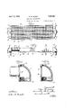
- Figure 1 is a plan view of the improved radiator.
- Fig. 2 is a side view of the radiator with one of the side plates thereof partly broken away.
- Fig. 3 is an enlarged sectional detail of one of the headers taken on the line 33 of Fig. 1.
- Fig. 4 is a sectional View similar to Fig. 3, but with the core tube omitted therefrom.
- Fig. 5 is an enlarged inner face View of one of the headers showing some of the coretubes in section.
- Fig. 6 is an enlarged sectional view taken on the line 6-6 of Fig. 2.
- Fig. 7 is a fragmentary perspective view partly in section showing one of the core tubes and some of the radiating fins thereon.
- Fig. 8 is a sectional detail taken on the line 88 of Fig. 5.
- Fig. 9 is a sectional detail of a modified form of header construction.
- Fig. 10 is a sectional detail of the tube and 66 header joint showing the tube reinforced locally.
- Fig. 11 is a side elevation of the heater with modified headers.
- Fig. 12 is an end view of the same.
- Figures 13 and 14 are corresponding views of a further modification.
- radiator core tubing in connection withthe form of apertures in the headers for receiving the tubing.
- the tubing is elliptical in crosssection, providing space between the adjacent parallel tubes of a Venturi-like form permitting the passage of air therebetween with 7 but small resistance, while the apertures in the headers'which receive the tubes are of flattened elliptical form, and the ends of the tubes are likewise flattened to fit these apertures.
- an elliptical form of tube may be employed without entailing diflicult machining in the tube receiving apertures of the headers.
- Another feature of the construction is that the tubes are inclined from header to header so that when the radiator is supported in a partly horizontal position, free drainage may take place from one header through the tubes to another.
- ribbed radiating fins which are mounted upon the tubes and carry fin protecting side plates which are drawn against or otherwise secured to the edges of the fins and add 90 strength and rigidity to the light core structure.
- the core of the radiator includes a plurality of horizontally spaced, parallel copper tubes 1, each of which 9 in cross-section is of elliptical form, leaving air channels between the tubes, suitably formed for the passage of air, with substantially no other resistance than the frictional resistance against the sides of the tubes.
- Fig. 3 The tubes or core of the radiator, as may be seen from Fig. 2,-are inclined downwardly from the inlet header 4 to the outlet header 5.
- the dot and dash line 8 in this view indicates a horizontal plane.
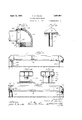
- Each of the headers is provided with a hexagonal portion 9 for the ap lication of a wrench to relieve the header 0 strain when 15 the conduits 10 are applied to the threaded openings therein.
- the smaller threaded openings 12 at the top of the headers are for the reception of air venting valves or plugs.
- the core of the radiator includes radlating fins 13 which may be formed from sheet copper. These fins are beaded or ribbed as indicated at 14 to add to their strength, and are provided with apertures 15 of elliptical form to receive the tubes. In forming these apertures an elliptical collar 16 is bent downwardly from the face to provide good contact with the tubes to which the fins are soldered at this point.
- the outer edges 17 of the fins engage side plates 18 which are held in contact with the which at their ends are tack soldered, riveted or welded to the side plates 18.
- the rods 19 preferably pass above and below in contact with the top and bottom of the tubes 1.
- the side plates 18 also have slits at the spaced points 20 thereon; through which solder is run to attach the plates to the edges of the fins, thus adding further rigidity to the radiator.
- the beads or ribs 14 stifien the fins and permit them to readily absorb pressure strains due to expansion and contraction of a the tubes so as to avoid irregular buckling and consequent noise at times of temperature change.
- the tubes are preferably made thicker at their ends than at their intermediate portions as illustrated in Fig. 8.
- the elliptical tube section provides the arch strength for resisting collapse when a partial vacuum forms within the tube without sacrificing the advantages of the elongated cross-section in reducing resistance to the flow of air between the tubes.
- the header casting 21 is rimmed or flanged at 22 to receive a bent-up marginal flange, or rim 23 of a cup-shaped header plate 24.
- the tubes 1 are brazed at 25 to an integral collarlike flange 26 on the hi ider plates and the marginal rims are brazed at 27.
- the header casting of Figs. 11 and 12 i provided with an integral apron or foot 28 which may rest on the floor to regulate the height of the heater.
- the feet 28 at opposite ends of the heater may be of different height to provide appropriate inclination for drainage of the tubes and to this end the aprons may be scored as at 29 to facilitate the removal of the bottom portion to reduce the height thereof.
- the castings 30 are provided with lugs 31 bored to receive supporting pins 32 which serve as feet and are adjusted by nuts 33 threaded thereon.
- the tube 1 is thickened and reinforced by inserting a lining 34 adjacent its ends to prevent overheating of the tube during brazing. After the lining is in place the tube may be swedged at its ends as hereinbefore described to fit the header apertures. It is desirable to have the heat transfer tubes as thin as is consistent with the pressures to which they are to be subjected but in brazing thin material to heavier material there is risk of overheating the thin material, which risk this reinforcing to a large extent obviates.
- a radiator comprising east end header elements, a core affording communication between the said header elements, and having parallel tubes. each of which is elliptical in cross-section throughout its length, but at its ends having its sides flattened to fiat-sided form, and said header elements having flatsided apertures fitting the ends of said tubes.
- a radiator comprising end header elements, a core affording communication between the said header elements, and comprising parallel tubes, each of which is elliptical in cross-section throughout its len h, but at its ends having its sides flattene to flat-sided form, and said header elements having flat-sided apertures into which the ends of said tubes fit, chamfers formed in the headers at the edges of said apertures, said chamfers being filled with metal for securing the tube to the header elements.
- a radiator comprising end header elements, a core afiording communication between said elements, and comprising arallel tubes, transverse radiating fins throug which said tubes pass, and side plates extending along the outer edges of said fins, said side plates being provided with spaced slits therein and soldered to the edges of said fins at said slits.
- a radiator core comprising tubes of elongated cross section, transverse fin plates perforated to fit said tubes and beaded in directions parallel to the long axes of said tube perforations, side plates engaging the ends of said fin plates, bond members rigidly connecting said side plates to each other, said side plates being perforated adjacent the ends of said bond members, and solder connecting said bond members and side plates at said perforations.
- a radiator core comprising tubes of elongated cross section, transverse fin plates perforated to fit said tubes and beaded between adjacent tubes, such beads extending in directions parallel to the long axes of said tube perforations, side plates engaging the ends of said fin plates, bond members rigidly connecting said side lates to each other, said side lates being per orated adjacent the ends of said bond members, and solder connecting said bond members and side plates at said perforations.
- a radiator tube having an elliptical cross-sectional form throughout the main portion of its length and having a fiat sided cross-sectional form at its ends, and an internal reinforcing sleeve disposed at each end of said tube, said sleeves extending into the elliptical sectioned portion of said tube and being formed with said tube to assure complete contact between the entire surface of said sleeves and said tube.
- a heater comprising a pair of headers, a plurality of tubes connecting said headers, and feet on said headers for supportin said heater from ahorizontal surface, sai feet having horizontal grooves located to reduce the cross-sectional area of said feet at a predetermined distance from their ends to facilitate breaking off a portion of and shortening certain of said feet and supporting said tubes in an inclined position.
Landscapes
- Engineering & Computer Science (AREA)
- Physics & Mathematics (AREA)
- Thermal Sciences (AREA)
- Mechanical Engineering (AREA)
- General Engineering & Computer Science (AREA)
- Geometry (AREA)
- Heat-Exchange Devices With Radiators And Conduit Assemblies (AREA)
Description
April 12, 1932. F M Y UNG 1,853,487
RADIATOR CONSTRUCTI 0N Filedfian. 51, 1931 s Sheets-Sheet 1 4 1a 1 19 6 8H6! |1( "T: .l -"791 13? mm Hm age;
April 12, 1932. YOUNG 1,853,487
RADIATOR CONSTRUCTION Filed Jan. 31, 1931 3 Sheets-Sheet 2 April 12, 1932. F. M. YOUNG RADIATOR CONSTRUCTION Filed Jan. 51, 1931 3 Sheets-Sheet 3 T 4 7K yea 75g.
Patented Apr. 12, 1932 UNITED STATES FRED M. YOUNG, OF RACINE, WISCONSIN RADIATOR ooNsTBUoTxoN Application filed January 31, 1931. Serial No. 512,520.
This invention relates to constructional features of radiators or heat transfer elements for various uses such as interior heating in steam, vapor, or hot water systems, or
'6 for the removal of heat from the cooling systems of internal combustion motors.
An object of the invention is to provide an improved tube and header combination which enables the use of tubes of elliptical form in cross-section while the header apertures for receiving the tubes may be fiatsided ellipses, enabling a more ready and convenient machining of the header elements than would be possible if the tube 15 openings in the header elements conformed to the general form of the tube. A further object of the invention is to provide a fin and side plate construction for this type of radiator which adds to its rigidity and strength while permitting free expansion and contraction of the radiator core under temperature changes. A still further object of the invention is to provide improvements in construction of the type of radiator to which this invention relates which will insure proper drainage of condensate, and uniform action throughout the radiator and the absence of air pockets therein.
The objects of the invention are accomplished by a construction as shown in the drawings, in which:
Figure 1 is a plan view of the improved radiator.
Fig. 2 is a side view of the radiator with one of the side plates thereof partly broken away.
Fig. 3 is an enlarged sectional detail of one of the headers taken on the line 33 of Fig. 1.
Fig. 4 is a sectional View similar to Fig. 3, but with the core tube omitted therefrom.
Fig. 5 is an enlarged inner face View of one of the headers showing some of the coretubes in section.
Fig. 6 is an enlarged sectional view taken on the line 6-6 of Fig. 2.
Fig. 7 is a fragmentary perspective view partly in section showing one of the core tubes and some of the radiating fins thereon.
Fig. 8 is a sectional detail taken on the line 88 of Fig. 5.
Fig. 9 is a sectional detail of a modified form of header construction.
Fig. 10 is a sectional detail of the tube and 66 header joint showing the tube reinforced locally.
Fig. 11 is a side elevation of the heater with modified headers.
Fig. 12 is an end view of the same.
Figures 13 and 14 are corresponding views of a further modification.
One of the principal characteristics of this radiator is the particular form of radiator core tubing in connection withthe form of apertures in the headers for receiving the tubing. The tubing is elliptical in crosssection, providing space between the adjacent parallel tubes of a Venturi-like form permitting the passage of air therebetween with 7 but small resistance, while the apertures in the headers'which receive the tubes are of flattened elliptical form, and the ends of the tubes are likewise flattened to fit these apertures. With this arrangement an elliptical form of tube may be employed without entailing diflicult machining in the tube receiving apertures of the headers.
Another feature of the construction is that the tubes are inclined from header to header so that when the radiator is supported in a partly horizontal position, free drainage may take place from one header through the tubes to another.
Another constructional feature, which will 86 be described more in detail further on, is the ribbed radiating fins which are mounted upon the tubes and carry fin protecting side plates which are drawn against or otherwise secured to the edges of the fins and add 90 strength and rigidity to the light core structure.
Referring to the drawings, the core of the radiator includes a plurality of horizontally spaced, parallel copper tubes 1, each of which 9 in cross-section is of elliptical form, leaving air channels between the tubes, suitably formed for the passage of air, with substantially no other resistance than the frictional resistance against the sides of the tubes.
fins preferably by the transverse rods 19,
ceiving the soldering or welding compound 7,
Fig. 3. The tubes or core of the radiator, as may be seen from Fig. 2,-are inclined downwardly from the inlet header 4 to the outlet header 5. The dot and dash line 8 in this view indicates a horizontal plane.
Each of the headers is provided with a hexagonal portion 9 for the ap lication of a wrench to relieve the header 0 strain when 15 the conduits 10 are applied to the threaded openings therein. The smaller threaded openings 12 at the top of the headers are for the reception of air venting valves or plugs.
The core of the radiator includes radlating fins 13 which may be formed from sheet copper. These fins are beaded or ribbed as indicated at 14 to add to their strength, and are provided with apertures 15 of elliptical form to receive the tubes. In forming these apertures an elliptical collar 16 is bent downwardly from the face to provide good contact with the tubes to which the fins are soldered at this point. I
The outer edges 17 of the fins engage side plates 18 which are held in contact with the which at their ends are tack soldered, riveted or welded to the side plates 18. The rods 19 preferably pass above and below in contact with the top and bottom of the tubes 1. The side plates 18 also have slits at the spaced points 20 thereon; through which solder is run to attach the plates to the edges of the fins, thus adding further rigidity to the radiator.
The beads or ribs 14 stifien the fins and permit them to readily absorb pressure strains due to expansion and contraction of a the tubes so as to avoid irregular buckling and consequent noise at times of temperature change.
To compensate for the change of a sectional shape and possible weakening of the walls of the tubes by overheating during the operation of brazing them into the header plate, the tubes are preferably made thicker at their ends than at their intermediate portions as illustrated in Fig. 8. I
The elliptical tube section provides the arch strength for resisting collapse when a partial vacuum forms within the tube without sacrificing the advantages of the elongated cross-section in reducing resistance to the flow of air between the tubes.
In the modified construction shown in Fig. 9, the header casting 21 is rimmed or flanged at 22 to receive a bent-up marginal flange, or rim 23 of a cup-shaped header plate 24.
65 The tubes 1 are brazed at 25 to an integral collarlike flange 26 on the hi ider plates and the marginal rims are brazed at 27.
The header casting of Figs. 11 and 12 i provided with an integral apron or foot 28 which may rest on the floor to regulate the height of the heater. The feet 28 at opposite ends of the heater may be of different height to provide appropriate inclination for drainage of the tubes and to this end the aprons may be scored as at 29 to facilitate the removal of the bottom portion to reduce the height thereof.
In the form shown in Figs. 13 and 14, the castings 30 are provided with lugs 31 bored to receive supporting pins 32 which serve as feet and are adjusted by nuts 33 threaded thereon.
In Fig. 10, the tube 1 is thickened and reinforced by inserting a lining 34 adjacent its ends to prevent overheating of the tube during brazing. After the lining is in place the tube may be swedged at its ends as hereinbefore described to fit the header apertures. It is desirable to have the heat transfer tubes as thin as is consistent with the pressures to which they are to be subjected but in brazing thin material to heavier material there is risk of overheating the thin material, which risk this reinforcing to a large extent obviates.
I claim:
1. A radiator comprising east end header elements, a core affording communication between the said header elements, and having parallel tubes. each of which is elliptical in cross-section throughout its length, but at its ends having its sides flattened to fiat-sided form, and said header elements having flatsided apertures fitting the ends of said tubes.
2. A radiator comprising end header elements, a core affording communication between the said header elements, and comprising parallel tubes, each of which is elliptical in cross-section throughout its len h, but at its ends having its sides flattene to flat-sided form, and said header elements having flat-sided apertures into which the ends of said tubes fit, chamfers formed in the headers at the edges of said apertures, said chamfers being filled with metal for securing the tube to the header elements.
3. A radiator comprising end header elements, a core afiording communication between said elements, and comprising arallel tubes, transverse radiating fins throug which said tubes pass, and side plates extending along the outer edges of said fins, said side plates being provided with spaced slits therein and soldered to the edges of said fins at said slits.
4. A radiator core comprising tubes of elongated cross section, transverse fin plates perforated to fit said tubes and beaded in directions parallel to the long axes of said tube perforations, side plates engaging the ends of said fin plates, bond members rigidly connecting said side plates to each other, said side plates being perforated adjacent the ends of said bond members, and solder connecting said bond members and side plates at said perforations.
5. A radiator core comprising tubes of elongated cross section, transverse fin plates perforated to fit said tubes and beaded between adjacent tubes, such beads extending in directions parallel to the long axes of said tube perforations, side plates engaging the ends of said fin plates, bond members rigidly connecting said side lates to each other, said side lates being per orated adjacent the ends of said bond members, and solder connecting said bond members and side plates at said perforations.
6. A radiator tube having an elliptical cross-sectional form throughout the main portion of its length and having a fiat sided cross-sectional form at its ends, and an internal reinforcing sleeve disposed at each end of said tube, said sleeves extending into the elliptical sectioned portion of said tube and being formed with said tube to assure complete contact between the entire surface of said sleeves and said tube.
7. A heater comprising a pair of headers, a plurality of tubes connecting said headers, and feet on said headers for supportin said heater from ahorizontal surface, sai feet having horizontal grooves located to reduce the cross-sectional area of said feet at a predetermined distance from their ends to facilitate breaking off a portion of and shortening certain of said feet and supporting said tubes in an inclined position.
Signed at Chicago this 23rd day of J anuary, 1931.
FRED M. YOUNG.
Priority Applications (1)
| Application Number | Priority Date | Filing Date | Title |
|---|---|---|---|
| US512520A US1853487A (en) | 1931-01-31 | 1931-01-31 | Radiator construction |
Applications Claiming Priority (1)
| Application Number | Priority Date | Filing Date | Title |
|---|---|---|---|
| US512520A US1853487A (en) | 1931-01-31 | 1931-01-31 | Radiator construction |
Publications (1)
| Publication Number | Publication Date |
|---|---|
| US1853487A true US1853487A (en) | 1932-04-12 |
Family
ID=24039445
Family Applications (1)
| Application Number | Title | Priority Date | Filing Date |
|---|---|---|---|
| US512520A Expired - Lifetime US1853487A (en) | 1931-01-31 | 1931-01-31 | Radiator construction |
Country Status (1)
| Country | Link |
|---|---|
| US (1) | US1853487A (en) |
Cited By (2)
| Publication number | Priority date | Publication date | Assignee | Title |
|---|---|---|---|---|
| US5966498A (en) * | 1996-08-07 | 1999-10-12 | Lakewood Engineering And Manufacturing Company | End closure assembly for oil-filled heater |
| US20080060797A1 (en) * | 2004-11-25 | 2008-03-13 | Masaaki Kitazawa | Heat Exchanger |
-
1931
- 1931-01-31 US US512520A patent/US1853487A/en not_active Expired - Lifetime
Cited By (2)
| Publication number | Priority date | Publication date | Assignee | Title |
|---|---|---|---|---|
| US5966498A (en) * | 1996-08-07 | 1999-10-12 | Lakewood Engineering And Manufacturing Company | End closure assembly for oil-filled heater |
| US20080060797A1 (en) * | 2004-11-25 | 2008-03-13 | Masaaki Kitazawa | Heat Exchanger |
Similar Documents
| Publication | Publication Date | Title |
|---|---|---|
| US2819731A (en) | Refrigerating apparatus | |
| JP6615118B2 (en) | Vehicle heat exchanger tube and vehicle radiator comprising such a tube | |
| EP0102715A2 (en) | Improvements relating to heat exchangers | |
| US3708012A (en) | Heat exchanger | |
| US1853487A (en) | Radiator construction | |
| CN114341580A (en) | Tank structure of heat exchanger | |
| US2573538A (en) | Heat exchanger conduit having internal fins | |
| US1956617A (en) | Radiator | |
| JP6256807B2 (en) | Heat exchanger and hot water device provided with the same | |
| US2661191A (en) | Heat exchanger | |
| IT201800004061A1 (en) | Air conditioning system for buses. | |
| US10274262B2 (en) | Heat exchanger | |
| JP2019095094A (en) | Reinforcement member and reinforcement structure of heat exchanger using the reinforcement member | |
| US1799691A (en) | Radiator construction | |
| US1895287A (en) | Fin radlator | |
| CN110392816A (en) | Heat exchanger with stiffening plate | |
| US3191670A (en) | Finned heat exchangers | |
| JPS5922153B2 (en) | A method of balancing different thermal expansions occurring during operation of a heat exchanger and a heat exchanger implementing the method | |
| US1775943A (en) | Radiator | |
| US1716459A (en) | Radiator | |
| US2179703A (en) | Header and manifold | |
| US1929937A (en) | Evaporator | |
| US1806186A (en) | Radiator | |
| JPS6229833Y2 (en) | ||
| US1752785A (en) | Radiator |