EP1830095A1 - Double clutch transmission for a motor vehicle - Google Patents
Double clutch transmission for a motor vehicle Download PDFInfo
- Publication number
- EP1830095A1 EP1830095A1 EP06425136A EP06425136A EP1830095A1 EP 1830095 A1 EP1830095 A1 EP 1830095A1 EP 06425136 A EP06425136 A EP 06425136A EP 06425136 A EP06425136 A EP 06425136A EP 1830095 A1 EP1830095 A1 EP 1830095A1
- Authority
- EP
- European Patent Office
- Prior art keywords
- input shaft
- gearbox
- friction
- clutch
- normally
- Prior art date
- Legal status (The legal status is an assumption and is not a legal conclusion. Google has not performed a legal analysis and makes no representation as to the accuracy of the status listed.)
- Granted
Links
Images
Classifications
-
- F—MECHANICAL ENGINEERING; LIGHTING; HEATING; WEAPONS; BLASTING
- F16—ENGINEERING ELEMENTS AND UNITS; GENERAL MEASURES FOR PRODUCING AND MAINTAINING EFFECTIVE FUNCTIONING OF MACHINES OR INSTALLATIONS; THERMAL INSULATION IN GENERAL
- F16D—COUPLINGS FOR TRANSMITTING ROTATION; CLUTCHES; BRAKES
- F16D25/00—Fluid-actuated clutches
- F16D25/08—Fluid-actuated clutches with fluid-actuated member not rotating with a clutching member
- F16D25/082—Fluid-actuated clutches with fluid-actuated member not rotating with a clutching member the line of action of the fluid-actuated members co-inciding with the axis of rotation
- F16D25/086—Fluid-actuated clutches with fluid-actuated member not rotating with a clutching member the line of action of the fluid-actuated members co-inciding with the axis of rotation the clutch being actuated by a push rod extending coaxially through the input or output shaft
-
- F—MECHANICAL ENGINEERING; LIGHTING; HEATING; WEAPONS; BLASTING
- F16—ENGINEERING ELEMENTS AND UNITS; GENERAL MEASURES FOR PRODUCING AND MAINTAINING EFFECTIVE FUNCTIONING OF MACHINES OR INSTALLATIONS; THERMAL INSULATION IN GENERAL
- F16D—COUPLINGS FOR TRANSMITTING ROTATION; CLUTCHES; BRAKES
- F16D21/00—Systems comprising a plurality of actuated clutches
- F16D21/02—Systems comprising a plurality of actuated clutches for interconnecting three or more shafts or other transmission members in different ways
- F16D21/06—Systems comprising a plurality of actuated clutches for interconnecting three or more shafts or other transmission members in different ways at least two driving shafts or two driven shafts being concentric
-
- F—MECHANICAL ENGINEERING; LIGHTING; HEATING; WEAPONS; BLASTING
- F16—ENGINEERING ELEMENTS AND UNITS; GENERAL MEASURES FOR PRODUCING AND MAINTAINING EFFECTIVE FUNCTIONING OF MACHINES OR INSTALLATIONS; THERMAL INSULATION IN GENERAL
- F16D—COUPLINGS FOR TRANSMITTING ROTATION; CLUTCHES; BRAKES
- F16D25/00—Fluid-actuated clutches
- F16D25/08—Fluid-actuated clutches with fluid-actuated member not rotating with a clutching member
- F16D25/082—Fluid-actuated clutches with fluid-actuated member not rotating with a clutching member the line of action of the fluid-actuated members co-inciding with the axis of rotation
- F16D25/087—Fluid-actuated clutches with fluid-actuated member not rotating with a clutching member the line of action of the fluid-actuated members co-inciding with the axis of rotation the clutch being actuated by the fluid-actuated member via a diaphragm spring or an equivalent array of levers
-
- F—MECHANICAL ENGINEERING; LIGHTING; HEATING; WEAPONS; BLASTING
- F16—ENGINEERING ELEMENTS AND UNITS; GENERAL MEASURES FOR PRODUCING AND MAINTAINING EFFECTIVE FUNCTIONING OF MACHINES OR INSTALLATIONS; THERMAL INSULATION IN GENERAL
- F16D—COUPLINGS FOR TRANSMITTING ROTATION; CLUTCHES; BRAKES
- F16D25/00—Fluid-actuated clutches
- F16D25/10—Clutch systems with a plurality of fluid-actuated clutches
-
- B—PERFORMING OPERATIONS; TRANSPORTING
- B60—VEHICLES IN GENERAL
- B60Y—INDEXING SCHEME RELATING TO ASPECTS CROSS-CUTTING VEHICLE TECHNOLOGY
- B60Y2400/00—Special features of vehicle units
- B60Y2400/42—Clutches or brakes
- B60Y2400/424—Friction clutches
- B60Y2400/4242—Friction clutches of dry type
-
- F—MECHANICAL ENGINEERING; LIGHTING; HEATING; WEAPONS; BLASTING
- F16—ENGINEERING ELEMENTS AND UNITS; GENERAL MEASURES FOR PRODUCING AND MAINTAINING EFFECTIVE FUNCTIONING OF MACHINES OR INSTALLATIONS; THERMAL INSULATION IN GENERAL
- F16D—COUPLINGS FOR TRANSMITTING ROTATION; CLUTCHES; BRAKES
- F16D21/00—Systems comprising a plurality of actuated clutches
- F16D21/02—Systems comprising a plurality of actuated clutches for interconnecting three or more shafts or other transmission members in different ways
- F16D21/06—Systems comprising a plurality of actuated clutches for interconnecting three or more shafts or other transmission members in different ways at least two driving shafts or two driven shafts being concentric
- F16D2021/0607—Double clutch with torque input plate in-between the two clutches, i.e. having a central input plate
-
- F—MECHANICAL ENGINEERING; LIGHTING; HEATING; WEAPONS; BLASTING
- F16—ENGINEERING ELEMENTS AND UNITS; GENERAL MEASURES FOR PRODUCING AND MAINTAINING EFFECTIVE FUNCTIONING OF MACHINES OR INSTALLATIONS; THERMAL INSULATION IN GENERAL
- F16D—COUPLINGS FOR TRANSMITTING ROTATION; CLUTCHES; BRAKES
- F16D21/00—Systems comprising a plurality of actuated clutches
- F16D21/02—Systems comprising a plurality of actuated clutches for interconnecting three or more shafts or other transmission members in different ways
- F16D21/06—Systems comprising a plurality of actuated clutches for interconnecting three or more shafts or other transmission members in different ways at least two driving shafts or two driven shafts being concentric
- F16D2021/0607—Double clutch with torque input plate in-between the two clutches, i.e. having a central input plate
- F16D2021/0615—Double clutch with torque input plate in-between the two clutches, i.e. having a central input plate the central input plate is supported by bearings in-between the two clutches
-
- F—MECHANICAL ENGINEERING; LIGHTING; HEATING; WEAPONS; BLASTING
- F16—ENGINEERING ELEMENTS AND UNITS; GENERAL MEASURES FOR PRODUCING AND MAINTAINING EFFECTIVE FUNCTIONING OF MACHINES OR INSTALLATIONS; THERMAL INSULATION IN GENERAL
- F16D—COUPLINGS FOR TRANSMITTING ROTATION; CLUTCHES; BRAKES
- F16D21/00—Systems comprising a plurality of actuated clutches
- F16D21/02—Systems comprising a plurality of actuated clutches for interconnecting three or more shafts or other transmission members in different ways
- F16D21/06—Systems comprising a plurality of actuated clutches for interconnecting three or more shafts or other transmission members in different ways at least two driving shafts or two driven shafts being concentric
- F16D2021/0607—Double clutch with torque input plate in-between the two clutches, i.e. having a central input plate
- F16D2021/0623—Double clutch with torque input plate in-between the two clutches, i.e. having a central input plate the central input plate having a damper in-between the two clutches
-
- F—MECHANICAL ENGINEERING; LIGHTING; HEATING; WEAPONS; BLASTING
- F16—ENGINEERING ELEMENTS AND UNITS; GENERAL MEASURES FOR PRODUCING AND MAINTAINING EFFECTIVE FUNCTIONING OF MACHINES OR INSTALLATIONS; THERMAL INSULATION IN GENERAL
- F16D—COUPLINGS FOR TRANSMITTING ROTATION; CLUTCHES; BRAKES
- F16D21/00—Systems comprising a plurality of actuated clutches
- F16D21/02—Systems comprising a plurality of actuated clutches for interconnecting three or more shafts or other transmission members in different ways
- F16D21/06—Systems comprising a plurality of actuated clutches for interconnecting three or more shafts or other transmission members in different ways at least two driving shafts or two driven shafts being concentric
- F16D2021/0669—Hydraulically actuated clutches with two clutch plates
-
- F—MECHANICAL ENGINEERING; LIGHTING; HEATING; WEAPONS; BLASTING
- F16—ENGINEERING ELEMENTS AND UNITS; GENERAL MEASURES FOR PRODUCING AND MAINTAINING EFFECTIVE FUNCTIONING OF MACHINES OR INSTALLATIONS; THERMAL INSULATION IN GENERAL
- F16D—COUPLINGS FOR TRANSMITTING ROTATION; CLUTCHES; BRAKES
- F16D21/00—Systems comprising a plurality of actuated clutches
- F16D21/02—Systems comprising a plurality of actuated clutches for interconnecting three or more shafts or other transmission members in different ways
- F16D21/06—Systems comprising a plurality of actuated clutches for interconnecting three or more shafts or other transmission members in different ways at least two driving shafts or two driven shafts being concentric
- F16D2021/0684—Mechanically actuated clutches with two clutch plates
-
- F—MECHANICAL ENGINEERING; LIGHTING; HEATING; WEAPONS; BLASTING
- F16—ENGINEERING ELEMENTS AND UNITS; GENERAL MEASURES FOR PRODUCING AND MAINTAINING EFFECTIVE FUNCTIONING OF MACHINES OR INSTALLATIONS; THERMAL INSULATION IN GENERAL
- F16D—COUPLINGS FOR TRANSMITTING ROTATION; CLUTCHES; BRAKES
- F16D2300/00—Special features for couplings or clutches
- F16D2300/14—Clutches which are normally open, i.e. not engaged in released state
-
- F—MECHANICAL ENGINEERING; LIGHTING; HEATING; WEAPONS; BLASTING
- F16—ENGINEERING ELEMENTS AND UNITS; GENERAL MEASURES FOR PRODUCING AND MAINTAINING EFFECTIVE FUNCTIONING OF MACHINES OR INSTALLATIONS; THERMAL INSULATION IN GENERAL
- F16D—COUPLINGS FOR TRANSMITTING ROTATION; CLUTCHES; BRAKES
- F16D2300/00—Special features for couplings or clutches
- F16D2300/24—Concentric actuation rods, e.g. actuation rods extending concentrically through a shaft
-
- Y—GENERAL TAGGING OF NEW TECHNOLOGICAL DEVELOPMENTS; GENERAL TAGGING OF CROSS-SECTIONAL TECHNOLOGIES SPANNING OVER SEVERAL SECTIONS OF THE IPC; TECHNICAL SUBJECTS COVERED BY FORMER USPC CROSS-REFERENCE ART COLLECTIONS [XRACs] AND DIGESTS
- Y10—TECHNICAL SUBJECTS COVERED BY FORMER USPC
- Y10T—TECHNICAL SUBJECTS COVERED BY FORMER US CLASSIFICATION
- Y10T74/00—Machine element or mechanism
- Y10T74/19—Gearing
- Y10T74/19219—Interchangeably locked
- Y10T74/19228—Multiple concentric clutch shafts
-
- Y—GENERAL TAGGING OF NEW TECHNOLOGICAL DEVELOPMENTS; GENERAL TAGGING OF CROSS-SECTIONAL TECHNOLOGIES SPANNING OVER SEVERAL SECTIONS OF THE IPC; TECHNICAL SUBJECTS COVERED BY FORMER USPC CROSS-REFERENCE ART COLLECTIONS [XRACs] AND DIGESTS
- Y10—TECHNICAL SUBJECTS COVERED BY FORMER USPC
- Y10T—TECHNICAL SUBJECTS COVERED BY FORMER US CLASSIFICATION
- Y10T74/00—Machine element or mechanism
- Y10T74/19—Gearing
- Y10T74/19219—Interchangeably locked
- Y10T74/19242—Combined gear and clutch
-
- Y—GENERAL TAGGING OF NEW TECHNOLOGICAL DEVELOPMENTS; GENERAL TAGGING OF CROSS-SECTIONAL TECHNOLOGIES SPANNING OVER SEVERAL SECTIONS OF THE IPC; TECHNICAL SUBJECTS COVERED BY FORMER USPC CROSS-REFERENCE ART COLLECTIONS [XRACs] AND DIGESTS
- Y10—TECHNICAL SUBJECTS COVERED BY FORMER USPC
- Y10T—TECHNICAL SUBJECTS COVERED BY FORMER US CLASSIFICATION
- Y10T74/00—Machine element or mechanism
- Y10T74/19—Gearing
- Y10T74/19219—Interchangeably locked
- Y10T74/19284—Meshing assisters
- Y10T74/19288—Double clutch and interposed transmission
Definitions
- the present invention relates to a double clutch transmission for a motor vehicle and, more particularly, to a friction clutch unit intended to be used in a transmission of this kind.
- Double clutch transmissions for motor vehicles are known, which comprise:
- the friction clutches can be either normally engaged, that is, configured so as to couple the drive shaft to the respective input shafts of the gearbox when no external command is imparted, or normally disengaged, that is, configured so as to keep the drive shaft and the respective input shafts of the gearbox uncoupled when no external command is imparted.
- axial or longitudinal are used to indicate a direction parallel to the axes of the shafts of the gearbox, whereas the terms “radial” or “transverse” are used to indicate a direction perpendicular to the said axial or longitudinal direction.
- the reference numeral 10 generally indicates a clutch unit suitable for selectively coupling a drive shaft drive shaft 12 of the motor vehicle (of which only the end portion facing the gearbox is illustrated) for rotation with either one of two coaxial input shafts 14 and 16 (of which only the end portion facing the engine is illustrated) of a gearbox for a motor vehicle, in this case a six-gear gearbox.
- gearbox is neither described nor illustrated in detail here, since it is to be regarded as generally known to the person skilled in the art. What is worth pointing up here is that one of the two input shafts, in this case the inner input shaft 14, carries the driving gearwheels associated to the odd gears (first, third and fifth), whereas the other input shaft, in this case the outer input shaft 16, carries the driving gearwheels associated to the even gears (second, fourth and sixth).
- the clutch unit 10 basically comprises a first normally-disengaged single-disc friction clutch 18 associated to the inner input shaft 14 and a second normally-engaged single-disc friction clutch 20 associated to the outer input shaft 16.
- the two friction clutches 18 and 20 are dry friction clutches.
- a double-mass flywheel is axially interposed between the clutch unit 10 and the drive shaft 12.
- the first mass of the flywheel 22 comprises a first element 24 facing the engine and a second element 26 facing the gearbox.
- the first element 24 is fixed at a radially inner portion thereof to the drive shaft 12 by means of screws 28 and at a radially outer portion thereof to the second element 26 by means of screws 30.
- the two elements 24 and 26 of the first mass of the flywheel 22 and the drive shaft 12 are therefore rigidly coupled for rotation with one another.
- a connection by means of splined profiles or ring gears could be provided.
- the first element 24 of the first mass of the flywheel 22 also has at its outer periphery a ring gear 32 arranged to mesh with a pinion of a starting electric motor (not illustrated) .
- the second mass of the flywheel 22 also comprises first and second disc-shaped elements 34 and 36, disposed on axially opposite sides of the second element 26 of the first mass and fixed to one another by means of screws 38.
- the second mass of the flywheel 22 is connected to the first mass, more specifically to the second element 26 of the first mass, through a torsional damper 40, preferably formed by a plurality of springs.
- the second mass del flywheel 22 is supported for rotation on the outer input shaft 16 of the gearbox by means of a radial ball bearing 41.
- the two elements 34 and 36 of the second mass of the flywheel 22 act as abutment members of the normally-disengaged friction clutch 18 associated to the inner input shaft 14 and of the normally-engaged friction clutch 20 associated to the outer input shaft 16, respectively.
- the normally-disengaged friction clutch 18 comprises a driven part rigidly connected for rotation with the inner input shaft 14 of the gearbox and a driving part connected for rotation to the drive shaft 16 through the flywheel 22.
- the driven part and the driving part of the friction clutch 18 are normally uncoupled for rotation with one another.
- the driven part of the friction clutch 18 comprises a hub 42 arranged so as to slide axially on a splined end portion 44 of the inner input shaft 14 of the gearbox and a friction disc 46 rigidly connected for rotation with a flanged portion 48 of the hub 42.
- the driving part of the friction clutch 18 comprises, in addition to the abutment member 34 forming the first element of the second mass of the flywheel 22, a cap 50 fixed by means of screws 52 to the periphery of the abutment member 34 and extending radially inwards on the axially opposite side of the abutment member 34 with respect to the friction disc 46, and a pressure plate 54, which is interposed between the friction disc 46 and the cap 50 and is rigidly connected for rotation with this latter by means of tangential tabs 56.
- the normally-disengaged friction clutch 18 further comprises:
- the normally-engaged friction clutch 20 comprises a driven part rigidly connected for rotation with the outer input shaft 16 of the gearbox and a driving part connected for rotation to the drive shaft 16 through the flywheel 22.
- the driving and driven parts have a structure similar to the one described above with reference to the friction clutch 18, the only difference being that in this case they are normally coupled for rotation with one another.
- the driven part of the friction clutch 20 comprises a hub 70 disposed so as to slide axially on a splined end portion 72 of the outer input shaft 16 of the gearbox and a friction disc 74 rigidly connected for rotation to a flanged portion 76 of the hub 70.
- the driving part of the friction clutch 20 comprises, in addition to the abutment member 36 forming the second element of the second mass of the flywheel 22, a cap 78 fixed by means of screws 80 to the periphery of the abutment member 36 and extending radially inwards on the axially opposite side of the friction disc 74 with respect to the abutment member 36 so as to divide the clutch unit 10 from the gearbox, and a pressure plate 82, which is interposed between the friction disc 74 and the cap 78 and is rigidly connected for rotation therewith by means of tangential tabs 84.
- the cap 78 is supported for rotation on a casing portion 86 of the gearbox by means of a radial ball bearing 88.
- the normally-engaged friction clutch 20 further comprises:
- the pressure plate 92 is supported for rotation by a portion of the control hydraulic piston 94 by means of a radial ball bearing 98, but is rigidly connected for translation with the piston 94. In this way, when the control hydraulic piston 94 is caused to displace leftwards, it pulls with it the pressure plate 92 and therefore the radially inner portion of the disc spring 90, thereby causing the disengagement of the friction clutch 20.
- the normally-engaged friction clutch being associated to the input shaft carrying the driving gearwheel corresponding to the highest gear (the sixth gear, in the illustrated embodiment)
- No actuator in fact, needs to be operated in order to ensure the engagement of the friction clutch intended to transmit the driving torque with the highest gear engaged.
- the normally-engaged friction clutch makes also possible to perform parking manoeuvres in second gear without the need of a special parking device which on the other hand would be necessary with a clutch unit having both the friction clutches of the normally-disengaged type.
- a further advantage of the clutch unit according to the invention is that the forces necessary for actuating the two friction clutches are opposed to one another.
- the actuation force of the normally-disengaged friction clutch is in fact directed rightwards, whereas the actuation force of the normally-engaged friction clutch is directed leftwards.
Landscapes
- Engineering & Computer Science (AREA)
- General Engineering & Computer Science (AREA)
- Mechanical Engineering (AREA)
- Mechanical Operated Clutches (AREA)
- Structure Of Transmissions (AREA)
- Arrangement And Mounting Of Devices That Control Transmission Of Motive Force (AREA)
- Hydraulic Clutches, Magnetic Clutches, Fluid Clutches, And Fluid Joints (AREA)
Abstract
Description
- The present invention relates to a double clutch transmission for a motor vehicle and, more particularly, to a friction clutch unit intended to be used in a transmission of this kind.
- Double clutch transmissions for motor vehicles are known, which comprise:
- a gearbox having a first input shaft carrying a plurality of driving gearwheels associated to the odd gears (first, third, fifth and seventh, if any) and a second input shaft carrying a plurality of driving gearwheels associated to the even gears (second, fourth and sixth, if present); and
- a clutch unit suitable for selectively coupling a drive shaft of the motor vehicle for rotation with either one of the two input shafts of the gearbox, the clutch unit including a first friction clutch, in particular a dry clutch, associated to the first input shaft and a second friction clutch, in particular a dry clutch, associated to the first input shaft.
- The friction clutches can be either normally engaged, that is, configured so as to couple the drive shaft to the respective input shafts of the gearbox when no external command is imparted, or normally disengaged, that is, configured so as to keep the drive shaft and the respective input shafts of the gearbox uncoupled when no external command is imparted.
- It is an object of the invention to provide a double clutch transmission for a motor vehicle in which the friction clutch unit has a reduced axial overall size and is properly arranged on the one hand to avoid damages to the gearbox and to prevent any danger situation for the driver, in case of breakdown to the transmission control system, and on the other hand to reduce to power consumption of the vehicle when it is running with the sixth gear engaged.
- This and other objects are fully achieved according to the invention by virtue of a double clutch transmission for a motor vehicle having the characteristics defined in independent claim 1.
- Further advantageous characteristics of the invention are defined in the dependent claims.
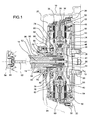
- The characteristics and the advantages of the invention will become apparent from the detailed description which follows, given purely by way of non-limiting example with reference to Figure 1 of the appended drawings, which shows a longitudinal section of a double clutch transmission for a motor vehicle, in particular of a clutch unit of the transmission, according to a preferred embodiment of the invention.
- In the following description and claims, the terms "axial" or "longitudinal" are used to indicate a direction parallel to the axes of the shafts of the gearbox, whereas the terms "radial" or "transverse" are used to indicate a direction perpendicular to the said axial or longitudinal direction.
- In Figure 1 the
reference numeral 10 generally indicates a clutch unit suitable for selectively coupling a driveshaft drive shaft 12 of the motor vehicle (of which only the end portion facing the gearbox is illustrated) for rotation with either one of twocoaxial input shafts 14 and 16 (of which only the end portion facing the engine is illustrated) of a gearbox for a motor vehicle, in this case a six-gear gearbox. - The gearbox is neither described nor illustrated in detail here, since it is to be regarded as generally known to the person skilled in the art. What is worth pointing up here is that one of the two input shafts, in this case the
inner input shaft 14, carries the driving gearwheels associated to the odd gears (first, third and fifth), whereas the other input shaft, in this case theouter input shaft 16, carries the driving gearwheels associated to the even gears (second, fourth and sixth). - The
clutch unit 10 basically comprises a first normally-disengaged single-disc friction clutch 18 associated to theinner input shaft 14 and a second normally-engaged single-disc friction clutch 20 associated to theouter input shaft 16. Preferably, the twofriction clutches - A double-mass flywheel, generally indicated 22, is axially interposed between the
clutch unit 10 and thedrive shaft 12. - The first mass of the flywheel 22 comprises a
first element 24 facing the engine and asecond element 26 facing the gearbox. Thefirst element 24 is fixed at a radially inner portion thereof to thedrive shaft 12 by means ofscrews 28 and at a radially outer portion thereof to thesecond element 26 by means ofscrews 30. The twoelements drive shaft 12 are therefore rigidly coupled for rotation with one another. However, as an alternative to a threaded connection between the twoelements first element 24 of the first mass of the flywheel 22 also has at its outer periphery aring gear 32 arranged to mesh with a pinion of a starting electric motor (not illustrated) . - The second mass of the flywheel 22 also comprises first and second disc-
shaped elements second element 26 of the first mass and fixed to one another by means ofscrews 38. The second mass of the flywheel 22 is connected to the first mass, more specifically to thesecond element 26 of the first mass, through atorsional damper 40, preferably formed by a plurality of springs. The second mass del flywheel 22 is supported for rotation on theouter input shaft 16 of the gearbox by means of a radial ball bearing 41. - As will be better explained in the following part of the description, the two
elements friction clutch 18 associated to theinner input shaft 14 and of the normally-engagedfriction clutch 20 associated to theouter input shaft 16, respectively. - The normally-
disengaged friction clutch 18 comprises a driven part rigidly connected for rotation with theinner input shaft 14 of the gearbox and a driving part connected for rotation to thedrive shaft 16 through the flywheel 22. The driven part and the driving part of thefriction clutch 18 are normally uncoupled for rotation with one another. - The driven part of the
friction clutch 18 comprises ahub 42 arranged so as to slide axially on asplined end portion 44 of theinner input shaft 14 of the gearbox and afriction disc 46 rigidly connected for rotation with a flangedportion 48 of thehub 42. The driving part of thefriction clutch 18 comprises, in addition to theabutment member 34 forming the first element of the second mass of the flywheel 22, acap 50 fixed by means ofscrews 52 to the periphery of theabutment member 34 and extending radially inwards on the axially opposite side of theabutment member 34 with respect to thefriction disc 46, and apressure plate 54, which is interposed between thefriction disc 46 and thecap 50 and is rigidly connected for rotation with this latter by means oftangential tabs 56. - The normally-disengaged
friction clutch 18 further comprises: - a
disc spring 58 which is mounted on the outer periphery of acontrol plate 60, rests with a radially intermediate portion thereof against thecap 50 and can abut axially with a radially outer portion thereof against thepressure plate 54; and - a
control rod 62 which is slidably arranged in a coaxialcylindrical cavity 64 of theinner input shaft 14 of the gearbox and is actuated, for example by ahydraulic piston 66 received in a cavity formed by acasing portion 68 of the gearbox facing towards the opposite side with respect to the engine, to push thecontrol plate 60 rightwards (with respect to an observer of Figure 1). - When no command is imparted to the
friction clutch 18 through thecontrol rod 62, the radially outer portion of thedisc spring 58 tends to remain detached from thepressure plate 54, while the radially inner portion tends to push thecontrol plate 60, and therefore thecontrol rod 62, leftwards. Thefriction disc 46 is not therefore pressed against theabutment member 34 and no torque is transmitted between the driving and driven parts of thefriction clutch 18. - On the other hand, when the
control rod 62 is pushed rightwards by thehydraulic piston 66, it pushes rightwards the radially inner portion of thedisc spring 58 through thecontrol plate 60. As a result, the radially outer portion of thedisc spring 58 is pushed leftwards against thepressure plate 54, thereby clamping thefriction disc 46 between thepressure plate 54 and theabutment member 34. The transmission of torque between the driving and driven parts of thefriction clutch 18 is thus ensured. - The normally-engaged
friction clutch 20 comprises a driven part rigidly connected for rotation with theouter input shaft 16 of the gearbox and a driving part connected for rotation to thedrive shaft 16 through the flywheel 22. The driving and driven parts have a structure similar to the one described above with reference to thefriction clutch 18, the only difference being that in this case they are normally coupled for rotation with one another. - The driven part of the
friction clutch 20 comprises ahub 70 disposed so as to slide axially on asplined end portion 72 of theouter input shaft 16 of the gearbox and afriction disc 74 rigidly connected for rotation to a flangedportion 76 of thehub 70. The driving part of thefriction clutch 20 comprises, in addition to theabutment member 36 forming the second element of the second mass of the flywheel 22, acap 78 fixed by means ofscrews 80 to the periphery of theabutment member 36 and extending radially inwards on the axially opposite side of thefriction disc 74 with respect to theabutment member 36 so as to divide theclutch unit 10 from the gearbox, and apressure plate 82, which is interposed between thefriction disc 74 and thecap 78 and is rigidly connected for rotation therewith by means oftangential tabs 84. Thecap 78 is supported for rotation on acasing portion 86 of the gearbox by means of a radial ball bearing 88. - The normally-engaged
friction clutch 20 further comprises: - a
disc spring 90 which is mounted on the outer periphery of apressure plate 92, abuts with a radially intermediate portion thereof against thepressure plate 82 and rests with a radially outer portion thereof on thecap 78, so as to exert in a rest condition a rightward axial thrust (with respect to an observer of Figure 1) tending to keep thefriction disc 74 clamped between thepressure plate 82 and theabutment member 36; and - a control
hydraulic piston 94 defining with thecasing portion 86 of the gearbox anannular space 96 suitable for being supplied with pressurized oil in order to cause thecontrol piston 94 to move axially leftwards. - The
pressure plate 92 is supported for rotation by a portion of the controlhydraulic piston 94 by means of a radial ball bearing 98, but is rigidly connected for translation with thepiston 94. In this way, when the controlhydraulic piston 94 is caused to displace leftwards, it pulls with it thepressure plate 92 and therefore the radially inner portion of thedisc spring 90, thereby causing the disengagement of thefriction clutch 20. - The advantages of a clutch unit according to the invention can be summarized in the following points.
- The use of dry clutches makes it possible to maximize the efficiency of the transmission with respect to the use of oil-bath clutches.
- By virtue of the normally-engaged friction clutch being associated to the input shaft carrying the driving gearwheel corresponding to the highest gear (the sixth gear, in the illustrated embodiment), the power consumption of the motor vehicle when it runs with the highest gear engaged, for example, on a motorway, is reduced. No actuator, in fact, needs to be operated in order to ensure the engagement of the friction clutch intended to transmit the driving torque with the highest gear engaged.
- Moreover, the normally-engaged friction clutch makes also possible to perform parking manoeuvres in second gear without the need of a special parking device which on the other hand would be necessary with a clutch unit having both the friction clutches of the normally-disengaged type.
- Since one of the two friction clutches is normally disengaged while the other is normally engaged, inconveniences, such as the breakage of one or more components of the gearbox, which might occur in case of failure of the transmission control system (be it an electric, an electronic and/or a hydraulic system) during the phase of the gear shift operation in which two gears are engaged at the same time, are also avoided without the need to use a special safety system which otherwise would be necessary with a clutch unit having both the friction clutches of the normally-engaged type.
- A further advantage of the clutch unit according to the invention is that the forces necessary for actuating the two friction clutches are opposed to one another. The actuation force of the normally-disengaged friction clutch is in fact directed rightwards, whereas the actuation force of the normally-engaged friction clutch is directed leftwards. This clearly makes it possible to cancel the axial actuation loads, which are born by the bearing 41 of the second mass of the flywheel, when the two friction clutches are actuated at the same time during a gear shift operation, and therefore to increase the life time of this bearing.
- Naturally, the principle of the invention remaining unchanged, the embodiments and details of construction could vary widely with respect to those described and illustrated purely by way of non-limiting example.
- For example, even though a hydraulic system for actuating the two friction clutches is illustrated in the description and the figures, other different ways of actuation can clearly be provided, for example of electromechanical type.
- Moreover, in a gearbox having six forward gears in which the driving gearwheels corresponding to the odd gears are arranged on the outer input shaft, instead of the inner one, and therefore the driving gearwheels corresponding to the even gears are arranged on the inner input shaft, instead of the outer one, it suffices to reverse the arrangement of the friction clutches shown in Figure 1, that is, to associate the normally-engaged friction clutch to the inner input shaft and the normally-disengaged friction clutch to the outer input shaft.
- Similar considerations apply to a gearbox with seven forward gears in which the driving gearwheel of seventh gear is arranged on the input shaft associated to the even gears.
Claims (5)
- Double clutch transmission with six or seven gears for a motor vehicle, comprisinga gearbox having first and second input shafts (14, 16) coaxial to one another, wherein the second input shaft (16) carries a driving gearwheel associated to the highest gear, anda clutch unit (10) having first and second friction clutches (18, 20) arranged to couple the drive shaft (12) of the motor vehicle respectively to the first (14) and second (16) input shafts of the gearbox,characterized in that the first friction clutch (18) is normally disengaged and the second friction clutch (20) is normally engaged.
- Transmission according to claim 1, wherein the first and second friction clutches (18, 20) are dry friction clutches.
- Six-gear transmission according to claim 1 or claim 2, wherein the first input shaft (14) carries a plurality of driving gearwheels associated to the odd gears, whereas the second input shaft (16) carries a plurality of driving gearwheels associated to the even gears.
- Seven-gear transmission according to claim 1 or claim 2, wherein the first input shaft (14) carries a plurality of driving gearwheels associated to the odd gears from the first gear to the fifth gear, whereas the second input shaft (16) carries a plurality of driving gearwheels associated to the even gears and to the seventh gear.
- Transmission according to any of the preceding claims, wherein the first input shaft (14) is arranged within the second input shaft (16).
Priority Applications (5)
| Application Number | Priority Date | Filing Date | Title |
|---|---|---|---|
| EP06425136A EP1830095B1 (en) | 2006-03-02 | 2006-03-02 | Double clutch transmission for a motor vehicle |
| AT06425136T ATE391859T1 (en) | 2006-03-02 | 2006-03-02 | DUAL CLUTCH TRANSMISSION FOR MOTOR VEHICLES |
| DE602006000908T DE602006000908T2 (en) | 2006-03-02 | 2006-03-02 | Double clutch transmission for motor vehicle |
| US11/612,949 US7779712B2 (en) | 2006-03-02 | 2006-12-19 | Double clutch transmission for a motor vehicle |
| CNB2006101562514A CN100485216C (en) | 2006-03-02 | 2006-12-27 | Double clutch transmission |
Applications Claiming Priority (1)
| Application Number | Priority Date | Filing Date | Title |
|---|---|---|---|
| EP06425136A EP1830095B1 (en) | 2006-03-02 | 2006-03-02 | Double clutch transmission for a motor vehicle |
Publications (2)
| Publication Number | Publication Date |
|---|---|
| EP1830095A1 true EP1830095A1 (en) | 2007-09-05 |
| EP1830095B1 EP1830095B1 (en) | 2008-04-09 |
Family
ID=36763822
Family Applications (1)
| Application Number | Title | Priority Date | Filing Date |
|---|---|---|---|
| EP06425136A Expired - Lifetime EP1830095B1 (en) | 2006-03-02 | 2006-03-02 | Double clutch transmission for a motor vehicle |
Country Status (5)
| Country | Link |
|---|---|
| US (1) | US7779712B2 (en) |
| EP (1) | EP1830095B1 (en) |
| CN (1) | CN100485216C (en) |
| AT (1) | ATE391859T1 (en) |
| DE (1) | DE602006000908T2 (en) |
Cited By (4)
| Publication number | Priority date | Publication date | Assignee | Title |
|---|---|---|---|---|
| WO2010020207A1 (en) * | 2008-08-22 | 2010-02-25 | Luk Lamellen Und Kupplungsbau Beteiligungs Kg | Dual clutch |
| WO2010020208A1 (en) * | 2008-08-22 | 2010-02-25 | Luk Lamellen Und Kupplungsbau Beteiligungs Kg | Dual clutch |
| WO2010020206A1 (en) * | 2008-08-22 | 2010-02-25 | Luk Lamellen Und Kupplungsbau Beteiligungs Kg | Actuator for a dual clutch |
| WO2017140535A1 (en) * | 2016-02-18 | 2017-08-24 | Continental Automotive Gmbh | Clutch assembly having vibration dampers and vehicle drive train |
Families Citing this family (10)
| Publication number | Priority date | Publication date | Assignee | Title |
|---|---|---|---|---|
| FR2896287B1 (en) * | 2006-01-18 | 2009-08-21 | Pascal Thery | DOUBLE CLUTCH FOR AUTOMOTIVE TRANSMISSION |
| CN101918740B (en) * | 2007-07-26 | 2014-06-11 | 格特拉格传动机构和齿轮工厂赫尔曼·哈根迈尔有限公司&两合公司 | Method for controlling a shifting up operation in a double-clutch transmission |
| CN101918237B (en) * | 2009-03-23 | 2013-06-05 | 丰田自动车株式会社 | Drive device for vehicle |
| ITTO20090750A1 (en) * | 2009-10-02 | 2011-04-03 | Oerlikon Graziano Spa | TRANSMISSION TO TWO SPEEDS FOR ELECTRIC VEHICLES |
| DE102010047803A1 (en) | 2009-10-19 | 2011-04-21 | Schaeffler Technologies Gmbh & Co. Kg | Torque transfer device |
| US8844390B2 (en) * | 2010-10-13 | 2014-09-30 | Hyundai Wia Corporation | Dual clutch transmission and dual clutch accuators thereof |
| WO2013079045A1 (en) * | 2011-11-30 | 2013-06-06 | Schaeffler Technologies AG & Co. KG | Assembly of a small dual clutch |
| CN103527661A (en) * | 2013-09-23 | 2014-01-22 | 吉林大学 | Double-clutch assembly of automobile dry double-clutch type automatic transmission |
| DE102014220126B4 (en) * | 2014-10-06 | 2022-12-01 | Schaeffler Technologies AG & Co. KG | Hybrid clutch for a double transmission unit of a motor vehicle and method for low-loss transmission of torque by means of the hybrid clutch |
| ITUA20161890A1 (en) * | 2016-03-22 | 2017-09-22 | Dana Graziano Srl | Friction clutch for vehicle transmission. |
Citations (6)
| Publication number | Priority date | Publication date | Assignee | Title |
|---|---|---|---|---|
| DE10231405A1 (en) * | 2001-07-11 | 2003-02-06 | Zf Sachs Ag | Multiple or double clutch arrangement has input shafts, input and output sides, and shared input side |
| US20030079953A1 (en) * | 2001-10-09 | 2003-05-01 | Zf Sachs Ag | Multi-clutch arrangement |
| US20040035666A1 (en) * | 2000-12-07 | 2004-02-26 | Wolfgang Grosspietsch | Double or multiple disk coupling device and disk arrangement therefor |
| FR2855229A1 (en) * | 2003-05-23 | 2004-11-26 | Renault Sa | GEARBOX WITH TWO CLUTCHES AND TWO SECONDARY SHAFTS |
| EP1544505A1 (en) * | 2003-12-18 | 2005-06-22 | C.R.F. Società Consortile per Azioni | A double-clutch transmission architecture for a motor vehicle |
| US20050262956A1 (en) * | 2004-05-25 | 2005-12-01 | David Janson | Dual clutch automatic transaxle |
Family Cites Families (9)
| Publication number | Priority date | Publication date | Assignee | Title |
|---|---|---|---|---|
| DE10253471A1 (en) * | 2002-11-16 | 2004-08-26 | Zf Friedrichshafen Ag | Gear shift device |
| DE10343994B4 (en) * | 2003-09-23 | 2017-10-05 | Zf Friedrichshafen Ag | Reverse gear arrangement in a countershaft transmission |
| JP4513370B2 (en) * | 2004-03-22 | 2010-07-28 | 日産自動車株式会社 | Twin clutch manual transmission |
| JP2006029476A (en) * | 2004-07-16 | 2006-02-02 | Nissan Motor Co Ltd | Driving force transmission device |
| US7219571B2 (en) * | 2004-11-15 | 2007-05-22 | Borgwarner, Inc. | Transmission having an electro-mechanical gear actuation system |
| DE102005005338B3 (en) * | 2005-01-27 | 2006-08-10 | Getrag Getriebe- Und Zahnradfabrik Hermann Hagenmeyer Gmbh & Cie Kg | Speed gearbox |
| US7246536B2 (en) * | 2005-03-17 | 2007-07-24 | Ford Global Technologies, Llc | Dual clutch kinematic arrangements with wide span |
| US7437963B2 (en) * | 2005-11-21 | 2008-10-21 | Gm Global Technology Operations, Inc. | Power transmission |
| US7467564B2 (en) * | 2006-03-13 | 2008-12-23 | Ford Global Technologies, Llc | Actuator mechanism for shift motors of a transmission |
-
2006
- 2006-03-02 EP EP06425136A patent/EP1830095B1/en not_active Expired - Lifetime
- 2006-03-02 AT AT06425136T patent/ATE391859T1/en not_active IP Right Cessation
- 2006-03-02 DE DE602006000908T patent/DE602006000908T2/en not_active Expired - Lifetime
- 2006-12-19 US US11/612,949 patent/US7779712B2/en not_active Expired - Fee Related
- 2006-12-27 CN CNB2006101562514A patent/CN100485216C/en not_active Expired - Fee Related
Patent Citations (6)
| Publication number | Priority date | Publication date | Assignee | Title |
|---|---|---|---|---|
| US20040035666A1 (en) * | 2000-12-07 | 2004-02-26 | Wolfgang Grosspietsch | Double or multiple disk coupling device and disk arrangement therefor |
| DE10231405A1 (en) * | 2001-07-11 | 2003-02-06 | Zf Sachs Ag | Multiple or double clutch arrangement has input shafts, input and output sides, and shared input side |
| US20030079953A1 (en) * | 2001-10-09 | 2003-05-01 | Zf Sachs Ag | Multi-clutch arrangement |
| FR2855229A1 (en) * | 2003-05-23 | 2004-11-26 | Renault Sa | GEARBOX WITH TWO CLUTCHES AND TWO SECONDARY SHAFTS |
| EP1544505A1 (en) * | 2003-12-18 | 2005-06-22 | C.R.F. Società Consortile per Azioni | A double-clutch transmission architecture for a motor vehicle |
| US20050262956A1 (en) * | 2004-05-25 | 2005-12-01 | David Janson | Dual clutch automatic transaxle |
Cited By (10)
| Publication number | Priority date | Publication date | Assignee | Title |
|---|---|---|---|---|
| WO2010020207A1 (en) * | 2008-08-22 | 2010-02-25 | Luk Lamellen Und Kupplungsbau Beteiligungs Kg | Dual clutch |
| WO2010020208A1 (en) * | 2008-08-22 | 2010-02-25 | Luk Lamellen Und Kupplungsbau Beteiligungs Kg | Dual clutch |
| WO2010020206A1 (en) * | 2008-08-22 | 2010-02-25 | Luk Lamellen Und Kupplungsbau Beteiligungs Kg | Actuator for a dual clutch |
| US8276727B2 (en) | 2008-08-22 | 2012-10-02 | Schaeffler Technologies AG & Co. KG | Dual clutch |
| US8360217B2 (en) | 2008-08-22 | 2013-01-29 | Schaeffler Technologies AG & Co. KG | Actuator for a dual clutch |
| CN102149934B (en) * | 2008-08-22 | 2014-11-05 | 舍弗勒技术股份两合公司 | Actuating device for a double clutch |
| US9175734B2 (en) | 2008-08-22 | 2015-11-03 | Schaeffler Technologies AG & Co. KG | Dual clutch |
| WO2017140535A1 (en) * | 2016-02-18 | 2017-08-24 | Continental Automotive Gmbh | Clutch assembly having vibration dampers and vehicle drive train |
| CN108603541A (en) * | 2016-02-18 | 2018-09-28 | 大陆汽车有限公司 | Clutch assembly with vibration damper and vehicle driveline |
| US11325456B2 (en) | 2016-02-18 | 2022-05-10 | Vitesco Technologies GmbH | Clutch assembly with vibration dampers and vehicle drive train |
Also Published As
| Publication number | Publication date |
|---|---|
| US20070204709A1 (en) | 2007-09-06 |
| ATE391859T1 (en) | 2008-04-15 |
| CN101029677A (en) | 2007-09-05 |
| US7779712B2 (en) | 2010-08-24 |
| EP1830095B1 (en) | 2008-04-09 |
| CN100485216C (en) | 2009-05-06 |
| DE602006000908D1 (en) | 2008-05-21 |
| DE602006000908T2 (en) | 2009-06-04 |
Similar Documents
| Publication | Publication Date | Title |
|---|---|---|
| US10018259B2 (en) | Gearbox for vehicles and vehicles comprising such a gearbox | |
| EP1830095B1 (en) | Double clutch transmission for a motor vehicle | |
| US8297424B2 (en) | Single actuator self-adjusting dry dual clutch | |
| US20110005345A1 (en) | Actuating arrangement for shift elements of a transmission | |
| US8123014B2 (en) | Two-way actuator device in a torque transmitting assembly | |
| US8584823B2 (en) | Torque transmitting assembly with dog clutch and plate clutch features | |
| EP2221509B1 (en) | A motor-vehicle transmission | |
| CN105358856B (en) | Multiple clutch arrangement and torque transfer device or clutch for commercial vehicles | |
| CN103998809B (en) | separation system | |
| CN104019208B (en) | Speed change device with hydraulic control mechanism | |
| CN105090266B (en) | Wet multi-clutch device and torque transmission device for vehicles | |
| KR102328092B1 (en) | Wet multi-plate clutch | |
| CN102139634A (en) | Double clutch for vehicles | |
| US7497312B2 (en) | Clutch assembly | |
| DE102005027608A1 (en) | Torque transmission system for drive train of vehicle, comprising lever unit to be used for control of dry as well as of wet clutch | |
| WO2013070440A1 (en) | Hybrid dual clutch transmission | |
| EP1610021A1 (en) | System for torque transmission device | |
| EP1753966B1 (en) | Clutch | |
| US20050252745A1 (en) | Dual clutch assembly for a motor vehicle powertrain | |
| US20050252749A1 (en) | Dual clutch assembly for a motor vehicle powertrain | |
| US20130081918A1 (en) | Pump drive launch device actuator | |
| CN111379797A (en) | Wet clutch unit and clutch comprising such wet clutch unit | |
| US20230286367A1 (en) | Pressure medium-actuated separating clutch which is normally closed, comprising an actuation device which rotates therewith and axially overlaps with a damper device | |
| CN101175928A (en) | Clutch device for motorcycle | |
| US5950490A (en) | Multi-clutched transmission system |
Legal Events
| Date | Code | Title | Description |
|---|---|---|---|
| PUAI | Public reference made under article 153(3) epc to a published international application that has entered the european phase |
Free format text: ORIGINAL CODE: 0009012 |
|
| 17P | Request for examination filed |
Effective date: 20061206 |
|
| AK | Designated contracting states |
Kind code of ref document: A1 Designated state(s): AT BE BG CH CY CZ DE DK EE ES FI FR GB GR HU IE IS IT LI LT LU LV MC NL PL PT RO SE SI SK TR |
|
| AX | Request for extension of the european patent |
Extension state: AL BA HR MK YU |
|
| GRAP | Despatch of communication of intention to grant a patent |
Free format text: ORIGINAL CODE: EPIDOSNIGR1 |
|
| GRAS | Grant fee paid |
Free format text: ORIGINAL CODE: EPIDOSNIGR3 |
|
| GRAA | (expected) grant |
Free format text: ORIGINAL CODE: 0009210 |
|
| AK | Designated contracting states |
Kind code of ref document: B1 Designated state(s): AT BE BG CH CY CZ DE DK EE ES FI FR GB GR HU IE IS IT LI LT LU LV MC NL PL PT RO SE SI SK TR |
|
| REG | Reference to a national code |
Ref country code: GB Ref legal event code: FG4D |
|
| REG | Reference to a national code |
Ref country code: CH Ref legal event code: EP |
|
| AKX | Designation fees paid |
Designated state(s): AT BE BG CH CY CZ DE DK EE ES FI FR GB GR HU IE IS IT LI LT LU LV MC NL PL PT RO SE SI SK TR |
|
| REG | Reference to a national code |
Ref country code: IE Ref legal event code: FG4D |
|
| REF | Corresponds to: |
Ref document number: 602006000908 Country of ref document: DE Date of ref document: 20080521 Kind code of ref document: P |
|
| PG25 | Lapsed in a contracting state [announced via postgrant information from national office to epo] |
Ref country code: SI Free format text: LAPSE BECAUSE OF FAILURE TO SUBMIT A TRANSLATION OF THE DESCRIPTION OR TO PAY THE FEE WITHIN THE PRESCRIBED TIME-LIMIT Effective date: 20080409 |
|
| NLV1 | Nl: lapsed or annulled due to failure to fulfill the requirements of art. 29p and 29m of the patents act | ||
| PG25 | Lapsed in a contracting state [announced via postgrant information from national office to epo] |
Ref country code: FI Free format text: LAPSE BECAUSE OF FAILURE TO SUBMIT A TRANSLATION OF THE DESCRIPTION OR TO PAY THE FEE WITHIN THE PRESCRIBED TIME-LIMIT Effective date: 20080409 Ref country code: NL Free format text: LAPSE BECAUSE OF FAILURE TO SUBMIT A TRANSLATION OF THE DESCRIPTION OR TO PAY THE FEE WITHIN THE PRESCRIBED TIME-LIMIT Effective date: 20080409 Ref country code: BG Free format text: LAPSE BECAUSE OF FAILURE TO SUBMIT A TRANSLATION OF THE DESCRIPTION OR TO PAY THE FEE WITHIN THE PRESCRIBED TIME-LIMIT Effective date: 20080709 Ref country code: ES Free format text: LAPSE BECAUSE OF FAILURE TO SUBMIT A TRANSLATION OF THE DESCRIPTION OR TO PAY THE FEE WITHIN THE PRESCRIBED TIME-LIMIT Effective date: 20080720 Ref country code: PT Free format text: LAPSE BECAUSE OF FAILURE TO SUBMIT A TRANSLATION OF THE DESCRIPTION OR TO PAY THE FEE WITHIN THE PRESCRIBED TIME-LIMIT Effective date: 20080911 |
|
| PG25 | Lapsed in a contracting state [announced via postgrant information from national office to epo] |
Ref country code: PL Free format text: LAPSE BECAUSE OF FAILURE TO SUBMIT A TRANSLATION OF THE DESCRIPTION OR TO PAY THE FEE WITHIN THE PRESCRIBED TIME-LIMIT Effective date: 20080409 Ref country code: AT Free format text: LAPSE BECAUSE OF FAILURE TO SUBMIT A TRANSLATION OF THE DESCRIPTION OR TO PAY THE FEE WITHIN THE PRESCRIBED TIME-LIMIT Effective date: 20080409 Ref country code: LV Free format text: LAPSE BECAUSE OF FAILURE TO SUBMIT A TRANSLATION OF THE DESCRIPTION OR TO PAY THE FEE WITHIN THE PRESCRIBED TIME-LIMIT Effective date: 20080409 |
|
| PG25 | Lapsed in a contracting state [announced via postgrant information from national office to epo] |
Ref country code: IS Free format text: LAPSE BECAUSE OF FAILURE TO SUBMIT A TRANSLATION OF THE DESCRIPTION OR TO PAY THE FEE WITHIN THE PRESCRIBED TIME-LIMIT Effective date: 20080809 |
|
| ET | Fr: translation filed | ||
| PG25 | Lapsed in a contracting state [announced via postgrant information from national office to epo] |
Ref country code: LT Free format text: LAPSE BECAUSE OF FAILURE TO SUBMIT A TRANSLATION OF THE DESCRIPTION OR TO PAY THE FEE WITHIN THE PRESCRIBED TIME-LIMIT Effective date: 20080409 Ref country code: CZ Free format text: LAPSE BECAUSE OF FAILURE TO SUBMIT A TRANSLATION OF THE DESCRIPTION OR TO PAY THE FEE WITHIN THE PRESCRIBED TIME-LIMIT Effective date: 20080409 Ref country code: DK Free format text: LAPSE BECAUSE OF FAILURE TO SUBMIT A TRANSLATION OF THE DESCRIPTION OR TO PAY THE FEE WITHIN THE PRESCRIBED TIME-LIMIT Effective date: 20080409 Ref country code: SE Free format text: LAPSE BECAUSE OF FAILURE TO SUBMIT A TRANSLATION OF THE DESCRIPTION OR TO PAY THE FEE WITHIN THE PRESCRIBED TIME-LIMIT Effective date: 20080709 |
|
| PLBE | No opposition filed within time limit |
Free format text: ORIGINAL CODE: 0009261 |
|
| STAA | Information on the status of an ep patent application or granted ep patent |
Free format text: STATUS: NO OPPOSITION FILED WITHIN TIME LIMIT |
|
| PG25 | Lapsed in a contracting state [announced via postgrant information from national office to epo] |
Ref country code: BE Free format text: LAPSE BECAUSE OF FAILURE TO SUBMIT A TRANSLATION OF THE DESCRIPTION OR TO PAY THE FEE WITHIN THE PRESCRIBED TIME-LIMIT Effective date: 20080409 Ref country code: RO Free format text: LAPSE BECAUSE OF FAILURE TO SUBMIT A TRANSLATION OF THE DESCRIPTION OR TO PAY THE FEE WITHIN THE PRESCRIBED TIME-LIMIT Effective date: 20080409 Ref country code: SK Free format text: LAPSE BECAUSE OF FAILURE TO SUBMIT A TRANSLATION OF THE DESCRIPTION OR TO PAY THE FEE WITHIN THE PRESCRIBED TIME-LIMIT Effective date: 20080409 |
|
| 26N | No opposition filed |
Effective date: 20090112 |
|
| PG25 | Lapsed in a contracting state [announced via postgrant information from national office to epo] |
Ref country code: EE Free format text: LAPSE BECAUSE OF FAILURE TO SUBMIT A TRANSLATION OF THE DESCRIPTION OR TO PAY THE FEE WITHIN THE PRESCRIBED TIME-LIMIT Effective date: 20080409 |
|
| PG25 | Lapsed in a contracting state [announced via postgrant information from national office to epo] |
Ref country code: CY Free format text: LAPSE BECAUSE OF FAILURE TO SUBMIT A TRANSLATION OF THE DESCRIPTION OR TO PAY THE FEE WITHIN THE PRESCRIBED TIME-LIMIT Effective date: 20080409 |
|
| PG25 | Lapsed in a contracting state [announced via postgrant information from national office to epo] |
Ref country code: MC Free format text: LAPSE BECAUSE OF NON-PAYMENT OF DUE FEES Effective date: 20090331 |
|
| PG25 | Lapsed in a contracting state [announced via postgrant information from national office to epo] |
Ref country code: IE Free format text: LAPSE BECAUSE OF NON-PAYMENT OF DUE FEES Effective date: 20090302 |
|
| PG25 | Lapsed in a contracting state [announced via postgrant information from national office to epo] |
Ref country code: GR Free format text: LAPSE BECAUSE OF FAILURE TO SUBMIT A TRANSLATION OF THE DESCRIPTION OR TO PAY THE FEE WITHIN THE PRESCRIBED TIME-LIMIT Effective date: 20080710 |
|
| REG | Reference to a national code |
Ref country code: CH Ref legal event code: PL |
|
| GBPC | Gb: european patent ceased through non-payment of renewal fee |
Effective date: 20100302 |
|
| PG25 | Lapsed in a contracting state [announced via postgrant information from national office to epo] |
Ref country code: CH Free format text: LAPSE BECAUSE OF NON-PAYMENT OF DUE FEES Effective date: 20100331 Ref country code: LI Free format text: LAPSE BECAUSE OF NON-PAYMENT OF DUE FEES Effective date: 20100331 |
|
| PG25 | Lapsed in a contracting state [announced via postgrant information from national office to epo] |
Ref country code: GB Free format text: LAPSE BECAUSE OF NON-PAYMENT OF DUE FEES Effective date: 20100302 |
|
| PG25 | Lapsed in a contracting state [announced via postgrant information from national office to epo] |
Ref country code: LU Free format text: LAPSE BECAUSE OF NON-PAYMENT OF DUE FEES Effective date: 20090302 |
|
| PG25 | Lapsed in a contracting state [announced via postgrant information from national office to epo] |
Ref country code: HU Free format text: LAPSE BECAUSE OF FAILURE TO SUBMIT A TRANSLATION OF THE DESCRIPTION OR TO PAY THE FEE WITHIN THE PRESCRIBED TIME-LIMIT Effective date: 20081010 |
|
| PG25 | Lapsed in a contracting state [announced via postgrant information from national office to epo] |
Ref country code: TR Free format text: LAPSE BECAUSE OF FAILURE TO SUBMIT A TRANSLATION OF THE DESCRIPTION OR TO PAY THE FEE WITHIN THE PRESCRIBED TIME-LIMIT Effective date: 20080409 |
|
| REG | Reference to a national code |
Ref country code: FR Ref legal event code: PLFP Year of fee payment: 11 |
|
| REG | Reference to a national code |
Ref country code: FR Ref legal event code: PLFP Year of fee payment: 12 |
|
| REG | Reference to a national code |
Ref country code: FR Ref legal event code: PLFP Year of fee payment: 13 |
|
| PGFP | Annual fee paid to national office [announced via postgrant information from national office to epo] |
Ref country code: FR Payment date: 20200331 Year of fee payment: 15 Ref country code: DE Payment date: 20200330 Year of fee payment: 15 |
|
| REG | Reference to a national code |
Ref country code: DE Ref legal event code: R119 Ref document number: 602006000908 Country of ref document: DE |
|
| PG25 | Lapsed in a contracting state [announced via postgrant information from national office to epo] |
Ref country code: DE Free format text: LAPSE BECAUSE OF NON-PAYMENT OF DUE FEES Effective date: 20211001 Ref country code: FR Free format text: LAPSE BECAUSE OF NON-PAYMENT OF DUE FEES Effective date: 20210331 |
|
| PGFP | Annual fee paid to national office [announced via postgrant information from national office to epo] |
Ref country code: IT Payment date: 20230224 Year of fee payment: 18 |
|
| PG25 | Lapsed in a contracting state [announced via postgrant information from national office to epo] |
Ref country code: IT Free format text: LAPSE BECAUSE OF NON-PAYMENT OF DUE FEES Effective date: 20240302 |