EP1829662A1 - Bauteil mit zwei Komponenten und Steckverbindungselement - Google Patents
Bauteil mit zwei Komponenten und Steckverbindungselement Download PDFInfo
- Publication number
- EP1829662A1 EP1829662A1 EP06004273A EP06004273A EP1829662A1 EP 1829662 A1 EP1829662 A1 EP 1829662A1 EP 06004273 A EP06004273 A EP 06004273A EP 06004273 A EP06004273 A EP 06004273A EP 1829662 A1 EP1829662 A1 EP 1829662A1
- Authority
- EP
- European Patent Office
- Prior art keywords
- component
- components
- component according
- cap
- connection
- Prior art date
- Legal status (The legal status is an assumption and is not a legal conclusion. Google has not performed a legal analysis and makes no representation as to the accuracy of the status listed.)
- Withdrawn
Links
- 239000000463 material Substances 0.000 claims abstract description 33
- 238000001746 injection moulding Methods 0.000 claims abstract description 4
- 239000004033 plastic Substances 0.000 claims description 10
- 229920002725 thermoplastic elastomer Polymers 0.000 claims description 7
- 229920001296 polysiloxane Polymers 0.000 claims description 4
- 238000002347 injection Methods 0.000 claims description 2
- 239000007924 injection Substances 0.000 claims description 2
- 238000003780 insertion Methods 0.000 description 3
- 230000037431 insertion Effects 0.000 description 3
- 238000000034 method Methods 0.000 description 3
- 238000011109 contamination Methods 0.000 description 1
- 238000002405 diagnostic procedure Methods 0.000 description 1
- 230000000694 effects Effects 0.000 description 1
- 238000004519 manufacturing process Methods 0.000 description 1
Images

Classifications
-
- H—ELECTRICITY
- H01—ELECTRIC ELEMENTS
- H01R—ELECTRICALLY-CONDUCTIVE CONNECTIONS; STRUCTURAL ASSOCIATIONS OF A PLURALITY OF MUTUALLY-INSULATED ELECTRICAL CONNECTING ELEMENTS; COUPLING DEVICES; CURRENT COLLECTORS
- H01R13/00—Details of coupling devices of the kinds covered by groups H01R12/70 or H01R24/00 - H01R33/00
- H01R13/44—Means for preventing access to live contacts
- H01R13/447—Shutter or cover plate
-
- B—PERFORMING OPERATIONS; TRANSPORTING
- B29—WORKING OF PLASTICS; WORKING OF SUBSTANCES IN A PLASTIC STATE IN GENERAL
- B29C—SHAPING OR JOINING OF PLASTICS; SHAPING OF MATERIAL IN A PLASTIC STATE, NOT OTHERWISE PROVIDED FOR; AFTER-TREATMENT OF THE SHAPED PRODUCTS, e.g. REPAIRING
- B29C45/00—Injection moulding, i.e. forcing the required volume of moulding material through a nozzle into a closed mould; Apparatus therefor
- B29C45/0081—Injection moulding, i.e. forcing the required volume of moulding material through a nozzle into a closed mould; Apparatus therefor of objects with parts connected by a thin section, e.g. hinge, tear line
-
- B—PERFORMING OPERATIONS; TRANSPORTING
- B29—WORKING OF PLASTICS; WORKING OF SUBSTANCES IN A PLASTIC STATE IN GENERAL
- B29C—SHAPING OR JOINING OF PLASTICS; SHAPING OF MATERIAL IN A PLASTIC STATE, NOT OTHERWISE PROVIDED FOR; AFTER-TREATMENT OF THE SHAPED PRODUCTS, e.g. REPAIRING
- B29C45/00—Injection moulding, i.e. forcing the required volume of moulding material through a nozzle into a closed mould; Apparatus therefor
- B29C45/16—Making multilayered or multicoloured articles
- B29C45/1676—Making multilayered or multicoloured articles using a soft material and a rigid material, e.g. making articles with a sealing part
-
- H—ELECTRICITY
- H01—ELECTRIC ELEMENTS
- H01R—ELECTRICALLY-CONDUCTIVE CONNECTIONS; STRUCTURAL ASSOCIATIONS OF A PLURALITY OF MUTUALLY-INSULATED ELECTRICAL CONNECTING ELEMENTS; COUPLING DEVICES; CURRENT COLLECTORS
- H01R13/00—Details of coupling devices of the kinds covered by groups H01R12/70 or H01R24/00 - H01R33/00
- H01R13/46—Bases; Cases
- H01R13/50—Bases; Cases formed as an integral body
- H01R13/501—Bases; Cases formed as an integral body comprising an integral hinge or a frangible part
-
- H—ELECTRICITY
- H01—ELECTRIC ELEMENTS
- H01R—ELECTRICALLY-CONDUCTIVE CONNECTIONS; STRUCTURAL ASSOCIATIONS OF A PLURALITY OF MUTUALLY-INSULATED ELECTRICAL CONNECTING ELEMENTS; COUPLING DEVICES; CURRENT COLLECTORS
- H01R13/00—Details of coupling devices of the kinds covered by groups H01R12/70 or H01R24/00 - H01R33/00
- H01R13/73—Means for mounting coupling parts to apparatus or structures, e.g. to a wall
- H01R13/74—Means for mounting coupling parts in openings of a panel
- H01R13/741—Means for mounting coupling parts in openings of a panel using snap fastening means
- H01R13/743—Means for mounting coupling parts in openings of a panel using snap fastening means integral with the housing
Definitions
- the invention relates to a component having at least two components, which are connected to each other via a hinge connection, and a plug connection element, which is formed by such a component.
- sockets are often provided, into which connectors are plugged into the diagnostic computer during an automated diagnostic process. If the socket is not in use, it must be covered to protect it against dirt or moisture. For this caps are put on.
- the cap is firmly connected to the socket and can not be lost, it is advantageous not to provide them individually, but to connect via a hinge connection with the socket.
- plastic components can be used here film hinges.
- the film hinges are often very rigid and allow opening the cap only against a high resilient resistance. Especially when plugging a plug into the socket, this can have a disabling effect. In particular, when used at very low temperatures, it may also come due to the cold-induced hardening to break a film hinge.
- Object of the present invention is to provide a component with two components, which are connected to each other via a hinge connection, wherein the hinge connection should be insensitive.
- the component according to the invention has a hinge connection between the first and second components, which is made of a softer material than at least one of the interconnected components.
- At least one of the two components interconnected by the hinge connection is made of a harder material to have sufficient mechanical stability, although the hinge connection itself is softer and more flexible. If the component consists of harder material, e.g. the socket of a connector, the material is chosen so that sufficient mechanical stability for the insertion process is present. On the other hand, the softer and more flexible joint connection ensures a simple and comfortable mutual flipping of the two components and a lower risk of breakage due to the greater flexibility.
- a simple manufacture is possible if the hinge connection and a first of the two components, which are interconnected by them, are made of the same material and the second component of a different material, wherein the material of the hinge connection and the first component is softer than that Material of the second component. In such an embodiment, only one point with a material change is present at the connection.
- the articulated connection is made of a softer material than both components which are connected to one another by it.
- only the hinge connection itself is formed by the softer material and the two components are made of a harder material that provides high stability. It is cost-effective, if the two components are made of a same material.
- the hinge connection plastic preferably thermoplastic elastomer (TPE) or silicone comprises.
- the material of the at least one component which is made of a harder material than the hinge connection, may also comprise plastic.
- the component when both components and the hinge connection are made of plastic, the component may comprise an injection molded part.
- a two-component injection molding method is used.
- the hinge connection comprises at least one film hinge.
- the invention can be used in components in which two components, at least one of which is to comprise a higher stability, should be connected by a resilient and secure joint connection, e.g. a box with a lid.
- a resilient and secure joint connection e.g. a box with a lid.
- this is e.g. advantageous if one of the two components comprises a cap which serves to cover the other component.
- the invention further relates to a connector element which is formed by a component according to the invention and e.g. a bush which can be covered by a cap, wherein the bush and the cap are connected to each other via a hinge connection, in particular at least one film hinge.
- a connector element which is formed by a component according to the invention and e.g. a bush which can be covered by a cap, wherein the bush and the cap are connected to each other via a hinge connection, in particular at least one film hinge.
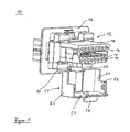
- the figures show a plug connection element 10 made of plastic. It comprises a component in the form of a socket 12 and a further component in the form of a cap 20.
- the socket 12 comprises in a conventional manner a rear mounting plate 13 and a plug receptacle 18 for insertion of a plug.
- the plug receptacle has contact receptacles 14, in which contact elements are provided, the electrical connections with corresponding contacts of an inserted plug available can make.
- Recesses 16 are provided on the lateral outer sides of the contact receptacle 18, of which only one is visible in the perspective view of FIG.
- the cap 20 is formed from the same material as the sleeve 12, the cap 20 is formed. On the side walls 21 inwardly facing projections 22 are provided, of which in the perspective view of FIG. 1, only one is visible. At the front end 23 of the cap 20, a handle 24 is provided on the outside thereof.
- the cap 20 is connected via film hinges 30, 32 with the bush 12.
- the film hinges 30, 32 are made of softer plastic material than both the cap 20 and the bushing 12.
- the film hinges are e.g. made of either thermoplastic elastomer (TPE) or silicone.
- the plug connection element according to the invention is used e.g. produced by two-component injection molding.
- the harder plastic material is injected into a mold that includes both the sleeve 12, the cap 20, and the hinge joints 30, 32.
- a pin is from the so-injected material in the form of that area corresponding to the joints 30, 32, removed.
- the softer plastic material e.g. TPE or silicone injected.
- the plug connection element is used as follows. In the closed state, which is shown in Fig. 2, the contact receptacles 14 of the connector receptacle 18 are covered and protected against contamination or moisture.
- the cap is in the closed position by the cooperation of the projections 22 on the inner sides the cap walls 21 are held with the recesses 16 on the side walls of the connector receptacle 18. If the socket 12 is to be connected to a plug, then the cap is opened on the handle 24 of the cap 20.
- the film hinges 30, 32 act as a hinge connection, so that the cap 20 can be folded away in the selected in Figs. 1 and 2 representation down. Now a plug can be inserted into the connector receptacle 18 of the socket 12.
- connection is less rigid than in known connectors, so that the cap 20, the insertion process of a plug into the connector receptacle 18 is not hindered, for example by a spring back of the cap 20.
Landscapes
- Engineering & Computer Science (AREA)
- Manufacturing & Machinery (AREA)
- Mechanical Engineering (AREA)
- Connector Housings Or Holding Contact Members (AREA)
Abstract
Die Erfindung betrifft ein Bauteil (10) mit wenigstens zwei Komponenten (12,20), die über eine Gelenkverbindung miteinander verbunden sind, wobei die Gelenkverbindung (30,32) aus einem weicheren Material gefertigt ist als zumindest eine der durch sie miteinander verbundenen Komponenten. Die Erfindung betrifft weiterhin ein Steckverbindungselement (10), das durch ein erfindungsgemäßes Bauteil gebildet ist.
Description
- Die Erfindung betrifft ein Bauteil mit wenigstens zwei Komponenten, die über eine Gelenkverbindung miteinander verbunden sind, und ein Steckverbindungselement, das durch ein solches Bauteil gebildet ist.
- Insbesondere im automobilen Bereich ist es oftmals notwendig, zwei Komponenten eines Bauteils gelenkig miteinander zu verbinden. So sind oftmals Buchsen vorgesehen, in die bei einem automatisierten Diagnoseprozess Verbindungsstecker zum Diagnosecomputer eingesteckt werden. Ist die Buchse gerade nicht in Benutzung, muss sie abgedeckt sein, um gegen Verschmutzungen oder Feuchtigkeit geschützt zu sein. Dazu werden Kappen aufgesetzt.
- Damit die Kappe fest mit der Buchse verbunden ist und nicht verloren gehen kann, ist es vorteilhaft, sie nicht einzeln vorzusehen, sondern über eine Gelenkverbindung mit der Buchse zu verbinden. Zum Beispiel bei Verwendung von Kunststoffkomponenten können hier Filmscharniere zum Einsatz kommen.
- Die Filmscharniere sind oftmals sehr starr und lassen ein Öffnen der Kappe nur gegen einen hohen federnden Widerstand zu. Gerade beim Einstecken eines Steckers in die Buchse kann dies behindernd wirken. Insbesondere bei Verwendung bei sehr niedrigen Temperaturen kann es außerdem aufgrund der kältebedingten Verhärtung zum Bruch eines Filmscharniers kommen.
- Aufgabe der vorliegenden Erfindung ist es, ein Bauteil mit zwei Komponenten anzugeben, die über eine Gelenkverbindung miteinander verbunden sind, wobei die Gelenkverbindung unempfindlich sein soll.
- Diese Aufgabe wird durch ein Bauteil mit den Merkmalen des Anspruchs 1 gelöst. Unteransprüche sind auf bevorzugte Ausführungsformen gerichtet. Besonders vorteilhafte Ausgestaltungen umfassen ein Steckverbindungselement gemäß Anspruch 10 oder Anspruch 11.
- Das erfindungsgemäße Bauteil weist eine Gelenkverbindung zwischen der ersten und zweiten Komponente auf, die aus einem weicheren Material gefertigt ist als zumindest eine der durch sie miteinander verbundenen Komponenten.
- Mindestens eine der beiden durch die Gelenkverbindung miteinander verbundenen Komponenten ist dementsprechend aus einem härteren Material gefertigt, um ausreichende mechanische Stabilität aufzuweisen, obwohl die Gelenkverbindung selbst weicher und flexibler ist. Umfasst die Komponente aus härterem Material z.B. die Buchse einer Steckverbindung, so wird das Material so gewählt, dass ausreichende mechanische Stabilität für den Einsteckprozess vorhanden ist. Andererseits gewährleistet die weichere und flexiblere Gelenkverbindung ein einfaches und komfortables gegenseitiges Klappen der beiden Komponenten und ein auf Grund der größeren Flexibilität geringeres Bruchrisiko.
- Eine einfache Herstellung ist möglich, wenn die Gelenkverbindung und eine erste der beiden Komponenten, die durch sie miteinander verbunden sind, aus demselben Material gefertigt sind und die zweite Komponente aus einem anderen Material, wobei das Material der Gelenkverbindung und der ersten Komponente weicher ist als das Material der zweiten Komponente. Bei einer solchen Ausgestaltung ist an der Verbindung nur eine Stelle mit einem Materialwechsel vorhanden.
- Besonders vorteilhaft ist es jedoch, wenn die Gelenkverbindung aus einem weicheren Material gefertigt ist als beide Komponenten, die von ihr miteinander verbunden sind. Bei einer solchen Ausgestaltung ist nur die Gelenkverbindung selbst durch das weichere Material gebildet und die beiden Komponenten sind aus härterem Material gefertigt, das eine hohe Stabilität zur Verfügung stellt. Kostengünstig ist es dabei, wenn die beiden Komponenten aus einem gleichen Material gefertigt sein.
- Einfach zu verarbeiten und im Betrieb problemlos sind Ausgestaltungen, bei denen die Gelenkverbindung Kunststoff, vorzugsweise thermoplastisches Elastomer (TPE) oder Silikon, umfasst.
- Das Material der wenigstens einen Komponente, die aus härterem Material gefertigt ist als die Gelenkverbindung, kann ebenfalls Kunststoff umfassen.
- Insbesondere, wenn beide Komponenten und die Gelenkverbindung aus Kunststoff bestehen, kann das Bauteil ein Spritzgussteil umfassen. Um die unterschiedlichen Materialien der Gelenkverbindung und der zwei durch sie miteinander verbundenen Komponenten zu realisieren, wird bei einer bevorzugten Ausgestaltung ein Zweikomponenten-Spritzgussverfahren eingesetzt.
- Besonders einfach ist eine Ausgestaltung, bei der die Gelenkverbindung wenigstens ein Filmscharnier umfasst.
- Die Erfindung lässt sich bei Bauteilen einsetzen, bei denen zwei Komponenten, von denen zumindest eine eine höhere Stabilität umfassen soll, durch eine belastbare und sichere Gelenkverbindung verbunden sein sollen, z.B. eine Box mit einem Deckel. Insbesondere ist dies z.B. vorteilhaft, wenn eine der beiden Komponenten eine Kappe umfasst, die zur Abdeckung der anderen Komponente dient.
- Die Erfindung betrifft weiterhin ein Steckverbindungselement, das durch ein erfindungsgemäßes Bauteil gebildet ist und z.B. eine Buchse umfasst, die durch eine Kappe abdeckbar ist, wobei die Buchse und die Kappe über eine Gelenkverbindung, insbesondere wenigstens ein Filmscharnier, miteinander verbunden sind.
- Die Erfindung wird anhand der beiliegenden Figuren im Detail erläutert, die eine Ausgestaltung eines erfindungsgemäßen Bauteils in Form eines Steckverbindungselementes darstellen. Dabei zeigt
- Fig. 1
- ein erfindungsgemäßes Steckverbindungselement mit geöffneter Kappe und
- Fig. 2
- das Steckverbindungselement mit geschlossener Kappe.
- Die Figuren zeigen ein Steckverbindungselement 10 aus Kunststoff. Es umfasst eine Komponente in Form einer Buchse 12 und eine weitere Komponente in Form einer Kappe 20. Bei der gezeigten Ausführungsform umfasst die Buchse 12 in an sich bekannter Weise eine rückwärtige Befestigungsplatte 13 und eine Steckeraufnahme 18 zum Einstecken eines Steckers. Die Steckeraufnahme weist Kontaktaufnahmen 14 auf, in denen Kontaktelemente vorgesehen sind, die mit entsprechenden Kontakten eines eingesteckten Steckers elektrische Verbindungen zur Verfügung stellen können. An den seitlichen Außenseiten der Kontaktaufnahme 18 sind Vertiefungen 16 vorgesehen, von denen in der perspektivischen Ansicht der Fig. 1 nur eine sichtbar ist.
- Aus demselben Material wie die Buchse 12 ist die Kappe 20 gebildet. An deren Seitenwänden 21 sind nach innen weisende Vorsprünge 22 vorgesehen, von denen in der perspektivischen Darstellung der Fig. 1 nur einer sichtbar ist. An dem Frontabschluß 23 der Kappe 20 ist an dessen Außenseite ein Griff 24 vorgesehen.
- Die Kappe 20 ist über Filmscharniere 30, 32 mit der Buchse 12 verbunden. Die Filmscharniere 30, 32 sind aus weicherem Kunststoffmaterial gefertigt als sowohl die Kappe 20 als auch die Buchse 12. Insbesondere sind die Filmscharniere z.B. entweder aus thermoplastischem Elastomer (TPE) oder Silikon gefertigt.
- Das erfindungsgemäße Steckverbindungselement wird z.B. im Zweikomponenten-Spritzgussverfahren hergestellt. Zunächst wird das härtere Kunststoffmaterial in eine Form eingespritzt, die sowohl die Buchse 12, die Kappe 20 als auch die Gelenkverbindungen 30, 32 umfasst. Zum Beispiel mit einem Stift wird aus dem so gespritzten Material noch in der Form derjenige Bereich, der den Gelenkverbindungen 30, 32 entspricht, entfernt. Hier wird jetzt das weichere Kunststoffmaterial, z.B. TPE oder Silikon eingespritzt.
- Das erfindungsgemäße Steckverbindungselement wird wie folgt verwendet. Im geschlossenen Zustand, der in Fig. 2 gezeigt ist, sind die Kontaktaufnahmen 14 der Steckeraufnahme 18 abgedeckt und gegen Verunreinigung oder Feuchtigkeitseintritt geschützt. Die Kappe wird in der geschlossenen Stellung durch das Zusammenwirken der Vorsprünge 22 an den Innenseiten der Kappenwände 21 mit den Vertiefungen 16 an den Seitenwänden der Steckeraufnahme 18 gehalten. Soll die Buchse 12 mit einem Stecker verbunden werden, so wird an dem Griff 24 der Kappe 20 die Kappe aufgeklappt. Dabei wirken die Filmscharniere 30, 32 als Gelenkverbindung, so dass die Kappe 20 in der in Fig. 1 und 2 gewählten Darstellung nach unten weggeklappt werden kann. Jetzt kann ein Stecker in die Steckeraufnahme 18 der Buchse 12 eingesteckt werden.
- Aufgrund der weicheren Gelenkverbindungen 30, 32 ist die Verbindung weniger starr als bei bekannten Steckverbindungen, so dass die Kappe 20 den Einsteckprozess eines Steckers in die Steckeraufnahme 18 nicht z.B. durch ein Zurückfedern der Kappe 20 behindert.
-
- 10
- Steckverbindungselement
- 12
- Buchse
- 13
- Befestigungsplatte
- 14
- Kontaktaufnahme
- 16
- Vertiefung
- 18
- Steckeraufnahme
- 20
- Kappe
- 21
- Seitenwand der Kappe
- 22
- Vorsprung
- 23
- Frontabschluss der Kappe
- 24
- Griff
- 30, 32
- Filmscharniere
Claims (11)
- Bauteil mit wenigstens zwei Komponenten (12, 20), die über eine Gelenkverbindung (30, 32) miteinander verbunden sind,
dadurch gekennzeichnet, dass
die Gelenkverbindung (30, 32) aus einem weicheren Material gefertigt ist als zumindest eine der durch sie miteinander verbundenen Komponenten (12, 20). - Bauteil nach Anspruch 1, dadurch gekennzeichnet, dass die Gelenkverbindung (30, 32) aus einem weicheren Material gefertigt ist als beide Komponenten (12, 20), die von ihr miteinander verbunden sind.
- Bauteil nach Anspruch 2, dadurch gekennzeichnet, dass die von der Gelenkverbindung (30, 32) miteinander verbundenen Komponenten (12, 20) aus dem gleichen Material gefertigt sind.
- Bauteil nach Anspruch 1, dadurch gekennzeichnet, dass die Gelenkverbindung und eine der beiden Komponenten, die durch sie miteinander verbunden sind, aus demselben ersten Material gefertigt sind, wobei das erste Material weicher ist, als das zweite Material, aus dem die zweite Komponente gefertigt ist.
- Bauteil nach einem der Ansprüche 1 bis 4, dadurch gekennzeichnet, dass das weichere Material Kunststoff, vorzugsweise thermoplastisches Elastomer (TPE) oder Silikon, umfasst.
- Bauteil nach einem der Ansprüche 1 bis 5, dadurch gekennzeichnet, dass das Material der wenigstens einen Komponente (12, 20), die aus härterem Material als die Gelenkverbindung (30, 32) gefertigt ist, Kunststoff umfasst.
- Bauteil nach einem der Ansprüche 1 bis 6, dadurch gekennzeichnet, dass die wenigstens zwei Komponenten (12, 20) und die Gelenkverbindung (30, 32) aus einem vorzugsweise in einem Zweikomponentenspritzgussverfahren hergestellten Spritzgussteil bestehen.
- Bauteil nach einem der Ansprüche 1 bis 7, dadurch gekennzeichnet, dass die Gelenkverbindung wenigstens ein Filmscharnier (30, 32) umfasst.
- Bauteil nach einem der Ansprüche 1 bis 8, dadurch gekennzeichnet, dass eine erste der beiden durch die Gelenkverbindung (30, 32) miteinander verbundenen Komponenten eine Kappe (20) für die zweite Komponente (12) umfasst.
- Steckverbindungselement (10), das durch ein Bauteil nach einem der Ansprüche 1 bis 9 gebildet ist.
- Steckverbindungselement (10), das durch ein Bauteil nach Anspruch 9 gebildet ist, wobei die zweite Komponente eine Buchse (12) umfasst, die durch die die Kappe (20) bildende erste Komponente abdeckbar ist.
Priority Applications (1)
| Application Number | Priority Date | Filing Date | Title |
|---|---|---|---|
| EP06004273A EP1829662A1 (de) | 2006-03-02 | 2006-03-02 | Bauteil mit zwei Komponenten und Steckverbindungselement |
Applications Claiming Priority (1)
| Application Number | Priority Date | Filing Date | Title |
|---|---|---|---|
| EP06004273A EP1829662A1 (de) | 2006-03-02 | 2006-03-02 | Bauteil mit zwei Komponenten und Steckverbindungselement |
Publications (1)
| Publication Number | Publication Date |
|---|---|
| EP1829662A1 true EP1829662A1 (de) | 2007-09-05 |
Family
ID=36750157
Family Applications (1)
| Application Number | Title | Priority Date | Filing Date |
|---|---|---|---|
| EP06004273A Withdrawn EP1829662A1 (de) | 2006-03-02 | 2006-03-02 | Bauteil mit zwei Komponenten und Steckverbindungselement |
Country Status (1)
| Country | Link |
|---|---|
| EP (1) | EP1829662A1 (de) |
Cited By (2)
| Publication number | Priority date | Publication date | Assignee | Title |
|---|---|---|---|---|
| WO2009115218A3 (de) * | 2008-03-18 | 2009-11-12 | Phoenix Contact Gmbh & Co. Kg | Elektrischer verbinder |
| DE202013003600U1 (de) * | 2013-04-17 | 2014-07-21 | Wiska Hoppmann & Mulsow Gmbh | Kabelverschraubung mit integralem Gelenk |
Citations (6)
| Publication number | Priority date | Publication date | Assignee | Title |
|---|---|---|---|---|
| JPS60247520A (ja) * | 1984-05-22 | 1985-12-07 | Nissei Plastics Ind Co | 合成樹脂成形品におけるヒンジ成形方法 |
| JPS61252120A (ja) * | 1985-05-02 | 1986-11-10 | Kamaya Kagaku Kogyo Co Ltd | 多色樹脂容器およびその製造方法 |
| DE19706734A1 (de) * | 1997-02-20 | 1998-08-27 | Opel Adam Ag | Entlüftungsvorrichtung und Verfahren zu ihrer Herstellung |
| JP2000128202A (ja) * | 1998-10-23 | 2000-05-09 | Yamashita Denki Kk | 開閉カバーおよび開閉カバー付き筐体 |
| US6649838B1 (en) * | 1998-07-21 | 2003-11-18 | Rudy A. Lopez, Sr. | Safety electrical outlet |
| JP2005262846A (ja) * | 2004-03-22 | 2005-09-29 | Gifu Plast Ind Co Ltd | ヒンジ付き射出成形品の成形方法及び射出成形用金型装置 |
-
2006
- 2006-03-02 EP EP06004273A patent/EP1829662A1/de not_active Withdrawn
Patent Citations (6)
| Publication number | Priority date | Publication date | Assignee | Title |
|---|---|---|---|---|
| JPS60247520A (ja) * | 1984-05-22 | 1985-12-07 | Nissei Plastics Ind Co | 合成樹脂成形品におけるヒンジ成形方法 |
| JPS61252120A (ja) * | 1985-05-02 | 1986-11-10 | Kamaya Kagaku Kogyo Co Ltd | 多色樹脂容器およびその製造方法 |
| DE19706734A1 (de) * | 1997-02-20 | 1998-08-27 | Opel Adam Ag | Entlüftungsvorrichtung und Verfahren zu ihrer Herstellung |
| US6649838B1 (en) * | 1998-07-21 | 2003-11-18 | Rudy A. Lopez, Sr. | Safety electrical outlet |
| JP2000128202A (ja) * | 1998-10-23 | 2000-05-09 | Yamashita Denki Kk | 開閉カバーおよび開閉カバー付き筐体 |
| JP2005262846A (ja) * | 2004-03-22 | 2005-09-29 | Gifu Plast Ind Co Ltd | ヒンジ付き射出成形品の成形方法及び射出成形用金型装置 |
Non-Patent Citations (4)
| Title |
|---|
| PATENT ABSTRACTS OF JAPAN vol. 010, no. 118 (M - 475) 2 May 1986 (1986-05-02) * |
| PATENT ABSTRACTS OF JAPAN vol. 011, no. 102 (M - 576) 31 March 1987 (1987-03-31) * |
| PATENT ABSTRACTS OF JAPAN vol. 2000, no. 08 6 October 2000 (2000-10-06) * |
| PATENT ABSTRACTS OF JAPAN vol. 2003, no. 12 5 December 2003 (2003-12-05) * |
Cited By (4)
| Publication number | Priority date | Publication date | Assignee | Title |
|---|---|---|---|---|
| WO2009115218A3 (de) * | 2008-03-18 | 2009-11-12 | Phoenix Contact Gmbh & Co. Kg | Elektrischer verbinder |
| US8678854B2 (en) | 2008-03-18 | 2014-03-25 | Phoenix Contact Gmbh & Co. Kg | Electrical connector for accommodating an electrical conductor and imparting shape |
| DE202013003600U1 (de) * | 2013-04-17 | 2014-07-21 | Wiska Hoppmann & Mulsow Gmbh | Kabelverschraubung mit integralem Gelenk |
| EP2793334B1 (de) * | 2013-04-17 | 2020-05-06 | Wiska Hoppmann & Mulsow GmbH | Kabelverschraubung mit integralem Gelenk |
Similar Documents
| Publication | Publication Date | Title |
|---|---|---|
| DE112019002139T5 (de) | Verstärktes Positionssicherungselement | |
| DE19858091A1 (de) | Elektrischer Verbinder mit verblockendem integrierten Scharnier | |
| EP1747603B1 (de) | Steckverbinder und verfahren seiner vormontage | |
| DE2743223A1 (de) | Kontakttraeger | |
| DE8613431U1 (de) | Verbinder mit einer Dichtung | |
| DE102018123621A1 (de) | Kontaktgehäuse für eine ladedose eines kraftfahrzeugs und verfahren zum herstellen einer ladedose eines kraftfahrzeugs | |
| EP2799650B1 (de) | Elektrische Kraftfahrzeugkomponente | |
| DE102004063814A1 (de) | Adapter zur Verwendung mit einem elektronischen Kleinstantrieb | |
| DE102019216763A1 (de) | Stromversorgungssteckverbindervorrichtung mit verbessertem Anschluss | |
| DE102018213920A1 (de) | Verbinder mit integralem Anschlusspositionssicherungsmechanismus | |
| DE4431281A1 (de) | Rastverbindung von Gehäuseteilen mit integriertem Sicherungsstift | |
| DE60001113T2 (de) | Leiterplatteneinkapselung | |
| EP3542424A1 (de) | Steckverbinderteil, insbesondere zum übertragen eines ladestroms zum aufladen eines elektrofahrzeugs | |
| DE102012212430B4 (de) | Verbindungseinrichtung für Leistungshalbleitereinrichtung mit dichtem Steckverbinder, Leistungshalbleitereinrichtung mit einer solchen Verbindungseinrichtung und Verfahren zur Ausbildung einer Verbindung mit einer solchen Verbindungseinrichtung | |
| DE202018101278U1 (de) | Steckverbindermodul für einen modularen Industriesteckverbinder zur Übertragung hoher Datenraten | |
| DE102021121353B3 (de) | Anordnung mit einer Kabelwanddurchführung für mehrere Kabel und Steckverbinder | |
| EP1763917A1 (de) | Gehäuseteil für eine antriebseinheit, sowie verfahren und werkzeug zur herstellung eines solchen | |
| EP1771052A2 (de) | Komponententräger zur Aufnahme von elektrischen/elektronischen Bauelementen in insbesondere Kraftfahrzeugtürschlössern | |
| DE102012105352A1 (de) | Positionierelement | |
| DE102009021667A1 (de) | Betätigungsvorrichtung | |
| DE202016100393U1 (de) | Wanddurchführung für einen Steckverbinder | |
| EP0692846A2 (de) | Verriegelbare Steckverbindung | |
| DE29823719U1 (de) | Kodiereinrichtung für ein Steckerpaar | |
| DE202019105325U1 (de) | Einschubbauteil und Bausatz für eine Kabelwanddurchführung | |
| DE102013215787B4 (de) | Gehäuse für einen elektrischen Stecker, Bausatz, Stecker und Steckverbindung |
Legal Events
| Date | Code | Title | Description |
|---|---|---|---|
| PUAI | Public reference made under article 153(3) epc to a published international application that has entered the european phase |
Free format text: ORIGINAL CODE: 0009012 |
|
| AK | Designated contracting states |
Kind code of ref document: A1 Designated state(s): AT BE BG CH CY CZ DE DK EE ES FI FR GB GR HU IE IS IT LI LT LU LV MC NL PL PT RO SE SI SK TR |
|
| AX | Request for extension of the european patent |
Extension state: AL BA HR MK YU |
|
| AKX | Designation fees paid | ||
| STAA | Information on the status of an ep patent application or granted ep patent |
Free format text: STATUS: THE APPLICATION IS DEEMED TO BE WITHDRAWN |
|
| 18D | Application deemed to be withdrawn |
Effective date: 20070306 |
|
| REG | Reference to a national code |
Ref country code: DE Ref legal event code: 8566 |