EP1829002B1 - Diebstahlsicherungsverfahren und vorrichtung mit drahtlosen technologien - Google Patents
Diebstahlsicherungsverfahren und vorrichtung mit drahtlosen technologien Download PDFInfo
- Publication number
- EP1829002B1 EP1829002B1 EP05822879A EP05822879A EP1829002B1 EP 1829002 B1 EP1829002 B1 EP 1829002B1 EP 05822879 A EP05822879 A EP 05822879A EP 05822879 A EP05822879 A EP 05822879A EP 1829002 B1 EP1829002 B1 EP 1829002B1
- Authority
- EP
- European Patent Office
- Prior art keywords
- dock
- monitored object
- peer
- leave
- information
- Prior art date
- Legal status (The legal status is an assumption and is not a legal conclusion. Google has not performed a legal analysis and makes no representation as to the accuracy of the status listed.)
- Expired - Lifetime
Links
Images


Classifications
-
- G—PHYSICS
- G08—SIGNALLING
- G08B—SIGNALLING SYSTEMS, e.g. PERSONAL CALLING SYSTEMS; ORDER TELEGRAPHS; ALARM SYSTEMS
- G08B13/00—Burglar, theft or intruder alarms
- G08B13/02—Mechanical actuation
- G08B13/14—Mechanical actuation by lifting or attempted removal of hand-portable articles
- G08B13/1427—Mechanical actuation by lifting or attempted removal of hand-portable articles with transmitter-receiver for distance detection
-
- G—PHYSICS
- G08—SIGNALLING
- G08B—SIGNALLING SYSTEMS, e.g. PERSONAL CALLING SYSTEMS; ORDER TELEGRAPHS; ALARM SYSTEMS
- G08B21/00—Alarms responsive to a single specified undesired or abnormal condition and not otherwise provided for
- G08B21/18—Status alarms
- G08B21/24—Reminder alarms, e.g. anti-loss alarms
-
- G—PHYSICS
- G08—SIGNALLING
- G08B—SIGNALLING SYSTEMS, e.g. PERSONAL CALLING SYSTEMS; ORDER TELEGRAPHS; ALARM SYSTEMS
- G08B21/00—Alarms responsive to a single specified undesired or abnormal condition and not otherwise provided for
-
- G—PHYSICS
- G08—SIGNALLING
- G08B—SIGNALLING SYSTEMS, e.g. PERSONAL CALLING SYSTEMS; ORDER TELEGRAPHS; ALARM SYSTEMS
- G08B25/00—Alarm systems in which the location of the alarm condition is signalled to a central station, e.g. fire or police telegraphic systems
- G08B25/01—Alarm systems in which the location of the alarm condition is signalled to a central station, e.g. fire or police telegraphic systems characterised by the transmission medium
- G08B25/10—Alarm systems in which the location of the alarm condition is signalled to a central station, e.g. fire or police telegraphic systems characterised by the transmission medium using wireless transmission systems
Definitions
- the present invention relates generally to an anti-theft method and apparatus, and more particularly, to an anti-theft method and apparatus by using short range wireless communication technologies.
- US 2002/0024448 A1 relates to a method and a system for monitoring a plurality of movable objects.
- a node includes a register of a number of transponders to be monitored. The node sends a signal to respective transponders at predetermined time intervals.
- a computer of a respective transponder provides a response signal with information concerning the identity of the transponder. If a transponder is detected to move in a non-permitted manner or to be located outside a permitted area in relation to the node in which the transponder is registered, the node is able to communicate with neighboring nodes in order to detect the transponder.
- the nodes are also able to communicate with a main node 30 which defines the conditions that are permissible with respect to a given transponder, and which also defines the conditions with respect to the transponder that shall initiate an alarm.
- the transponder is mounted to a boat in a harbour and monitored by a node. If the boat leaves its position or leaves the monitored area without permission, there is initiated via the node or via the main node an alarm which passes to the subscriber telephone so that the subscriber obtains this information.
- DE 200 03 583 U1 relates to a luggage alarm system wherein each piece of luggage of a person is provided with a slave station.
- a master station is carried by the person.
- the master station periodically emits a signal to the slave station. If a maximum distance between the master station and a slave station is exceeded, the slave station sends a command to alarm to the master station and eventually activates an alarm itself.
- the alarm has to be receipted and shut off via the master station, eventually secured by a PIN code.
- US 6,127,931 relates to a device for monitoring the movement of a person.
- the device includes a base unit and a homing transmitter unit being worn by a person to be monitored.
- the device generates an alarm signal when the person travels outside a predetermined area.
- US 6,331,817 B1 relates to an object tracking apparatus and method.
- An organizer is provided capable of communicating with a variety of objects in its environment. Using an input device, the user creates different sets of objects associated with a specific event. Once the organizer has been set up with different sets and associations to events, the organizer will track the objects in the sets and provide the user with indications when the objects are not appropriately accounted for..
- US 2002/0008625 A1 relates to a remote accountability system and method.
- the system has at least one command post system and at least one portable remote system. Data is collected from sensor systems by portable unit and transmitted to command post system.
- the command post system and the portable units establish a master-slave relationship. If an out of range portable unit finds a portable unit which is in communication with command post system, it will communicate the that portable unit and use it as a relay to the command post system.
- the portable units have a plurality of input/output devices which may contain a smartcard reader for reading user information and identification data from a smartcard.
- An object of the present invention is to provide an anti-theft method and apparatus, with which alarm signals are generated timely when a monitored public device is brought out of the predefined surveillance area without authorization.
- An anti-theft method to be executed in an active peer comprising: transmitting radio RF signals to a passive peer, to detect whether one of the active peer and the passive peer as a monitored object is in the coverage area of the radio range of the other one of the active peer and the passive peer as a dock; checking whether the monitored object is permitted to leave the dock when detecting that the monitored object is going to leave the area of the dock; sending an alarm signal to an alarm apparatus if the monitored object is not permitted to leave the dock.
- An anti-theft method to be executed in a surveillance server comprising: receiving the alarm signal sent from an active peer, the alarm signal signifying that a monitored object leaves the coverage area of the radio range of a dock without authorization, wherein one of the monitored object and the dock having power supply component acts as the active peer while the other one acts as a passive peer to receive radio RF signals sent from the active peer; generating an alarm indication based on the alarm signal.
- An active apparatus comprising: a transmitting unit, for transmitting radio RF signals to a passive peer, to detect whether one of the active peer and the passive peer as a monitored object is in the coverage area of the radio range of the other one of the active peer and the passive peer as a dock; a detecting unit, for checking whether the monitored object is permitted to leave the dock when detecting that the monitored object is going to leave the area of the dock; wherein the transmitting unit sends an alarm signal to the surveillance server if the checking result shows that the monitored object is not permitted to leave the dock.
- a surveillance server comprising: a receiving unit, for receiving the alarm signal sent from an active peer, the alarm signal signifying that a monitored object leaves the coverage area of the radio range of a dock without authorization, wherein one of the monitored object and the dock having power supply component acts as the active peer while the other one acts as a passive peer to receive radio RF signals sent from the active peer; an alarming unit, for generating an alarm indication based on the alarm signal.
- a mobile device such as mobile phone, PDA and portable computer, generally has several communication interfaces.
- One or more wireless communication interfaces are often included in these interfaces, to support wireless communication based on WLAN, Bluetooth, Near Field Communication or RFID technologies.
- a mobile device equipped with the wireless communication interfaces shoulders the responsibility of restricting itself in the surveillance area within the reach of the radio range and sending alarm signals to the surveillance server when the mobile device is brought out of the surveillance area without permission, in addition to normal communication functionality within a certain area.
- the present invention aims to establish a secure anti-theft system for public shared articles similar to the mobile device.
- a passive peer gets the working power through being activated by a active peer, and then establishes radio link with the active peer.
- the one having power supply component acts as the active peer, while the other one acts as the passive peer.
- the mobile device leaves the surveillance area of the dock without permission, that is, the radio link between the mobile device and the dock breaks after the mobile device moves out of the radio range of Mifare, one party acting as the active peer sends alarm signals to the surveillance server to warn that the mobile device is being stolen possibly.
- the anti-theft system in the present invention provides two surveillance modes, taking the mobile device and the dock as the active peer respectively. Two specific embodiments will be given below to describe the two surveillance modes.
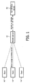
- Fig.1 is the schematic diagram illustrating the anti-theft system where alarm signals are sent to the surveillance server via the mobile device (i.e. the mobile device acts as the active peer) in accordance with an embodiment of the present invention.
- a plurality of docks 10 can be deployed in a predefined surveillance area (e.g. office building or plant area), each dock 10 acting as an active peer.
- mobile device 40 According to the radio range of Mifare (usually 10 cm), mobile device 40 having power supply component and acting as the active peer, reports the identification information of the dock to which it belongs to surveillance server 50 when detecting a dock 10 in its radio range.
- the coverage area of the radio signals transferred between dock 10 and mobile device 40 with dock 10 at the center is called governing area of dock 10.
- mobile device 40 detects that it leaves the dock to which it belongs and enters the governing areaof another dock 10
- it reports the identification information of the new dock to which it belongs to surveillance server 50.
- the mobile device 40 detects that it leaves the predefined surveillance area without permission, it sends alarm signals to surveillance server 50.
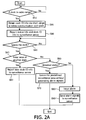
- the mobile device attempts to establish radio link with each dock and thus detects whether there exists a dock in its radio range (step S10).
- the mobile device keeps on sending radio signals to detect whether there exists a dock in its radio range. If there exists a dock in the radio range of the radio signal, the dock activated by the radio signal establishes radio link with the mobile device. Once the mobile device detects a dock, it transfers into locked state automatically (i.e. not allowed to leave the governing area of the dock without permission). At this time, the radio link between the mobile device and the dock is just like an electronic lock, locking mobile device 40 in the governing area of the dock.
- the mobile device obtains the identification information of the dock to which it belongs via the short range wireless communication with the dock (step S20), wherein the identity of the dock can be a string of symbols, like 200070, or a character string indicating location information, like workshop A.
- the mobile device After acquiring the identification information of the dock to which it belongs, the mobile device reports the status information indicating it is in locked status together with the identification information of the dock to which it belongs, to the surveillance server via WLAN or WWAN (step S30).
- a monitoring module in the mobile device is enabled to detect whether it has left the dock to which it belongs, that is, detect whether the radio link between the mobile device and the dock to which it belongs breaks (step S40).
- the mobile device can also detects at predefined intervals (2 second, for example) whether it has left the dock to which it belongs and reports the detection results to the surveillance server regularly, which can enable the surveillance server failing to receive any detection result in a predefined time period to issue an alarm, and thus prevent the thief from cutting the power supply component and thus stealing the mobile device, compared with the detection mode adopting shift sensor.
- the mobile device moving in the governing area of a dock could leave the governing area of the dock and enter the governing area of another dock, or could leave the predefined whole surveillance area formed by a plurality of docks, so we should first determine whether the mobile device moves into the governing area of a new dock (step S45).
- the mobile device detects that it has entered the governing area of a new dock, after obtaining the identification information of the new dock via short range wireless communication, it reports the identification information of the new dock to the surveillance server (step S50).
- the mobile device checks whether the current status has changed from locked status to unlocked status (step S60).
- the mobile device can receive user ID (i.e. user name) and/or password from user input via smart card or keyboard. After performing authentication procedure with the surveillance server and receiving the confirmation message indicating that the inputted user ID and/or password are/is from an authorized user, the mobile device changes from locked status to unlocked status (that is, it has been granted the authorization to leave the governing area of the dock).
- user ID i.e. user name
- password i.e. password
- the mobile device After performing authentication procedure with the surveillance server and receiving the confirmation message indicating that the inputted user ID and/or password are/is from an authorized user, the mobile device changes from locked status to unlocked status (that is, it has been granted the authorization to leave the governing area of the dock).
- step S70 If the mobile device is in unlocked status currently, it can leave the predefined surveillance area without generating alarm signals (step S70); however, if the mobile device is still in locked status, it will issue an alarm through its own alarm apparatus (step S80), and send an alarm signal to the surveillance server to warn the surveillance server that the mobile device is possibly being stolen (step S90).
- the mobile device will resumes to locked status from unlocked status automatically if the mobile device in unlocked status hasn't left the governing area of the dock to which it belongs within a predefined time period, thus to prevent the mobile device from being stolen by unauthorized users during the use intermission of an authorized user.
- the mobile device also reports its latest status information to the surveillance server after resuming to locked status automatically, so that the surveillance server can update the recorded status information of the mobile device in time.
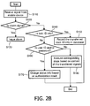
- Fig.2B describes the steps to be executed in surveillance server 50 of the anti-theft system as shown in Fig.1 .
- the surveillance server receives signals sent from the mobile device via WLAN or WWAN (step S110), it first determines whether the transferred signals are alarm signal (step S 120).
- the surveillance server issues an alarm and displays the alarm signal on a display means (step S 130), wherein the display means can be a display screen at the surveillance server or a lighting means for alarming controlled by the surveillance server and the lighting means is deployed in the predefined surveillance area formed by the plurality of docks.
- the display means can be a display screen at the surveillance server or a lighting means for alarming controlled by the surveillance server and the lighting means is deployed in the predefined surveillance area formed by the plurality of docks.
- step S140 If the transferred signals are not alarm signal, it's to be determined whether the transferred signals are the identification information of the dock to which the mobile device belongs (step S140). If the answer is yes, the transferred identification information of the dock to which the mobile device belongs will be recorded in the database of the surveillance server and the status information of the mobile device in locked status will be recorded in the database of the surveillance server too (step S 150); if the answer is no, it's to be determined whether the transferred signals are user ID and/or password for unlocking (step S 160).
- the surveillance server determines whether the user ID and/or password are/is correct. If yes, the status of the mobile device recorded in the database is set to unlocked status and the confirmation information about the authorization is sent to the mobile device (step S170).
- the surveillance server executes the corresponding operation based on the content of the transferred signals (step S 180). For example, if the mobile device detects whether it has left the dock to which it belongs at predefined intervals (such as 2s), the surveillance server checks whether it has received the report of the detection result as scheduled. If failing to receive the report of detection result within a predefined time period, the surveillance server not only issues an alarm but also displays the alarm signals on a display means.
- predefined intervals such as 2s
- the surveillance server can also display and track the current position of each guarded mobile device and the related information on the display screen in real time, based on the recorded status information of each mobile device and the identification information of the dock to which it belongs. For example, whether the mobile device is within the surveillance area currently: if the mobile device is in the surveillance area, the identification information of the specific dock will be displayed; whether someone is using the mobile device currently: if it's being used now, the identification information of the specific user will be displayed.
- Fig.3 is the schematic diagram illustrating the anti-theft system sending alarm signals to the surveillance server via the docks (i.e. the dock is the active peer) in accordance with another embodiment of the present invention.
- a plurality of docks 10 can be deployed in a predefined surveillance area (e.g. office building or plant area), each dock 10 comprising an active peer.
- each dock sends radio signals to detect whether there exists mobile device 40 within its surveillance area, and reports the information about the mobile device to surveillance server 50 after finding mobile device 40.
- the dock sends alarm signals to surveillance server 50.
- the coverage area with the dock 10 as center and the radio range as radius is called the surveillance area of the dock 10.
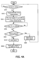
- Fig.4A and Fig.4B illustrate respectively the steps to be executed in dock 10 and those in surveillance server 50 shown in Fig.3 .
- a dock sends radio signals to detect whether there exists a mobile device within its surveillance area (step S310). If a mobile device is in the surveillance area of the dock, the mobile device activated by the radio signals will establish radio link with the dock.
- the dock acquires the identification information of the mobile device via the short range wireless communication with the mobile device (step S320). Same as the above embodiment, the dock sets the status of the mobile device in its surveillance area to locked status when establishing the radio link. Through the radio link between the mobile device and the dock, the mobile device is locked in the surveillance area of the dock in form of an electronic lock.
- the dock reports to the surveillance server via wire/wireless LAN or wire/wireless WAN its identity and the current status information of the mobile device within its surveillance area (step S330).
- the dock determines whether the mobile device leaves its surveillance area based on detecting whether the radio link between the mobile device and the dock breaks (step S340).
- the dock detects that the mobile device is leaving its surveillance area, it detects whether the current status of the mobile device within its surveillance area has changed to unlocked status from locked status (step S350).
- the dock can receive user ID and/or password from user input via smart card or keyboard. After performing authentication procedure with the surveillance server and receiving the confirmation message indicating that the inputted user ID and/or password are/is from an authorized user, the dock changes the current status of the mobile device within its surveillance area from locked status to unlocked status.
- the dock has unlocked all mobile devices in its surveillance area
- the unlocked status should have a strict time restriction in order to prevent the mobile devices within the surveillance area from being stolen by unauthorized users, e.g. the time limit is 2 seconds for every unlocking.
- the dock detects a mobile device in its surveillance area after the time limit expires, the dock changes the current status of the mobile device within its surveillance area from unlocked status to locked status again.
- the dock reports the latest status information of the mobile devices in its surveillance area to the surveillance server so that the surveillance server can update the recorded status information of the mobile devices in time.
- step S350 If the dock detects at step S350 that a mobile device within the surveillance area of the dock is in unlocked status, the mobile device can leave the surveillance area without being generated alarm signals (step S360); however, if the mobile device is still in locked status, the dock not only issues alarm (step S370) but also sends to the surveillance server an alarm signal, to warn the surveillance server that the mobile device within the surveillance area of the dock is possibly being stolen (step S380).
- the dock reports regularly to the surveillance server at predefined intervals (2 second, for example) the detection result about the mobile devices within its surveillance area, which can enable the surveillance server to issue an alarm when failing to receive the detection report as scheduled, and thus avoid the case that the thief cuts the power supply component and thus steals the mobile device.
- Fig.4B illustrates the steps to be executed in the surveillance server of the anti-theft system shown in Fig.3 .
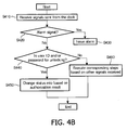
- the surveillance server receives signals transferred via wire/wireless LAN or wire/wireless WAN from the dock (step S410), it first determines whether the transferred signals are alarm signal (step S420).
- the surveillance server issues alarms and displays the alarm signals on a display means (step S430).
- step S440 If the transferred signals are not alarm signal, it's to be determined whether the transferred signals are the user ID and/or password of the mobile device within the surveillance area of the dock from user input via smart card or keyboard (step S440).
- the surveillance server determines whether the user ID and/or password are/is correct. If yes, set the status of the mobile device recorded in the database to unlocked status and send the confirmation information about the authorization to the dock (step S450).
- the surveillance server executes the corresponding operation based on the transferred signals (step S460). For example, if the transferred signals are information reported from the dock about resuming the status of mobile devices within its surveillance area from unlocked status to locked status after a predefined time limit expires, the surveillance server will update the recorded status information of the mobile devices timely based on the report.
- the surveillance server if the surveillance server fails to receive the detection report from the dock about the status of the mobile devices within its surveillance area as schedule, the surveillance server not only issues an alarm but also displays the alarm signals on a display means.
- the proposed anti-theft system equipped with Mifare communication interface can also be implemented with other short range wireless communication protocols. If NFC (Near Field Communication) interface is employed, both the dock and the mobile device can act as the active peer, thus to realize peer-to-peer communication mode, or abbreviated as P2P communication mode.
- NFC Near Field Communication
- P2P communication mode when the present invention adopts P2P communication mode, the implementations of the above two specific embodiments can have various modifications.
- P2P communication mode when P2P communication mode is applied in the above second embodiment, user authentication can be performed via the radio link between the mobile device and the surveillance server.
- the dock when the dock detects a mobile device in the surveillance area attempts to leave the surveillance area, the dock checks whether the current status of the mobile device has changed from locked status to unlocked status, through sending a poll request to the mobile device.
- the mobile device feeds the authorization information from the surveillance server as poll response back to the dock, so that the dock can monitor each mobile device within its surveillance area and send alarm signals timely and accurately to the surveillance server when an unauthorized user steals the mobile device.
- Mifare communication interface with the dock as the active peer while the mobile device as the passive peer can be employed, so as to simplify the configuration of the mobile device.
- the dock equipped with a reader can read information on the tag in a wireless way, thus to realize the above surveillance procedure. It's equally applicable to the surveillance of other expensive articles, if only a Mifare tag is pasted on the monitored expensive article.
- NFC interfaces with both the dock and the mobile device as the active peer can be applied to realize surveillance operations.
- the anti-theft method using short range wireless communication technologies in the present invention can be implemented in software or in hardware, or in combination of both.
- Fig.5 illustrates the configurations of the active peer for sending alarm signals to the surveillance server and the surveillance server for generating alarms in accordance with an embodiment of the present invention when the proposed anti-theft method is implemented in hardware, wherein the components same as those in conventional active peers based on Mifare and conventional servers are not given here.
- the one having power supply component acts as the active peer and the other one as the passive peer.
- the one as the active peer is responsible for sending alarm signals to the surveillance server, to alert that the mobile device is possibly being stolen.
- the active peer 100 such as dock 10 in Fig.3 (or alternatively mobile device 40 in Fig.1 ), comprises: a transmitting unit 110, for transmitting radio RF signals to a passive peer, to detect whether the mobile device is in the coverage area of the radio range of a dock having the active peer; a detecting unit 120, for checking whether the mobile device is permitted to leave the dock when detecting that the mobile device is going to leave the area of the dock (it's assumed that the mobile device is initialized unallowed to leave the dock to which it belongs at default ); wherein the transmitting unit sends an alarm signal to a surveillance server 200 if the checking result shows that the monitored object is not permitted to leave the dock.
- a transmitting unit 110 for transmitting radio RF signals to a passive peer, to detect whether the mobile device is in the coverage area of the radio range of a dock having the active peer
- a detecting unit 120 for checking whether the mobile device is permitted to leave the dock when detecting that the mobile device is going to leave the area of the dock (it's
- the active peer 100 further comprises: a receiving unit 130, for receiving information about user ID and/or password from user input via smart card or keyboard; and the active peer sends the user ID and/or password to the surveillance server 200 via transmitting unit 110.
- determining unit 210 determines whether the mobile device is permitted to leave the dock based on the user ID and/or password, and sends the determination result to the active peer via transmitting unit 240.
- Receiving unit 130 in the active peer 100 receives the determination result from surveillance server 200, so as to provide updated information when the above detecting unit 120 checks whether the mobile device is allowed to leave the dock.
- alarming unit 230 will generate an alarm, to alert that some mobile device within the surveillance area of the dock is possibly being stolen.
- the public shared mobile devices are locked in the surveillance area constructed by several docks in the form of electronic lock.
- an alarm signal will be sent timely to a surveillance server controlled by the administrator, and thus the proposed anti-theft system can effectively prevent public articles from being stolen.
- the surveillance server can provide the current position of the monitored public article and related user information, the anti-theft system is advantageous to the establishment and improvement for management of public shared articles.
Landscapes
- Physics & Mathematics (AREA)
- General Physics & Mathematics (AREA)
- Business, Economics & Management (AREA)
- Emergency Management (AREA)
- Engineering & Computer Science (AREA)
- Computer Networks & Wireless Communication (AREA)
- Burglar Alarm Systems (AREA)
- Alarm Systems (AREA)
- Transceivers (AREA)
- Transmitters (AREA)
- Emergency Alarm Devices (AREA)
Claims (14)
- Diebstahlsicherungsverfahren, auszuführen in einem aktiven Peer (100), das die Schritte umfasst:a) Übertragung eines Funk-Hochfrequenzsignals an einen passiven Peer, um festzustellen, ob sich entweder der aktive Peer (100) oder der passive Peer als überwachtes Objekt (40) in einem Bereich befindet, der von der Funkreichweite des anderen aktiven Peers (100) und passiven Peers als ein Dock (10) abgedeckt ist,b) Überprüfen, ob das überwachte Objekt (40) berechtigt ist, das Dock (10) zu verlassen, wenn festgestellt wird, dass das überwachte Objekt (40) den Bereich des Docks (10) verlassen wird,c) Senden eines Alarmsignals an eine Alarmvorrichtung, wenn das überwachte Objekt (40) nicht zum Verlassen des Docks (10) berechtigt ist, wobei die Alarmvorrichtung ein Überwachungsserver (50,200) ist und der Überwachungsserver (50, 200) das Alarmsignal drahtgebunden oder drahtlos empfängt, undwobei das Verfahren ferner die Schritte umfasst:Empfangen von durch einen Benutzer eingegebenen Informationen, dass es dem überwachten Objekt (40) gestattet ist, das Dock (10) zu verlassen,Senden der eingegebenen Informationen an den Überwachungsserver (50, 200),Empfangen von Antwortinformationen vom Überwachungsserver (50,200), ob der Benutzer ein berechtigter Benutzer ist, wobei die Antwortinformationen durch Entscheidung des Überwachungsservers (50, 200) erzielt wird, der auf der Grundlage der Eingabeinformationen entscheidet, ob das überwachte Objekt berechtigt ist, das Dock zu verlassen.
- Diebstahlsicherungsverfahren nach Anspruch 1, wobei Schritt a) ferner umfasst:Melden der festgestellten Information, ob sich das überwachte Objekt (40) im Bereich des Docks (10) befindet, an den Überwachungsserver (50, 200).
- Diebstahlsicherungsverfahren nach Anspruch 1, wobei die eingegebenen Informationen Benutzerkennung und/oder Passwort umfassen.
- Diebstahlsicherungsverfahren nach Anspruch 1, wobei der Benutzer die Informationen über eine Chipkarte oder Tastatur eingibt.
- Diebstahlsicherungsverfahren nach einem der Ansprüche 1 bis 2, wobei bei Schritt (a) der aktive Peer (100) periodisch Funk-Hochfrequenzsignale sendet, um festzustellen, ob sich das überwachte Objekt (40) im Bereich des Docks (10) befindet.
- Diebstahlsicherungsverfahren nach einem der Ansprüche 1 bis 2, wobei, wenn das überwachte Objekt (40) der aktive Peer (100) ist, das Verfahren ferner den Schritt umfasst:Feststellen, ob das überwachte Objekt (40) bewegt wird,Einleiten der Abarbeitung von Schritt (a), wenn festgestellt wird, dass das überwachte Objekt (40) bewegt wird.
- Diebstahlsicherungsverfahren, auszuführen in dem in Anspruch 1 genannten Überwachungsserver (50, 200), das die Schritte umfasst:Empfangen eines von einem aktiven Peer (100) gesendeten Alarmsignals, wobei das Alarmsignal anzeigt, dass ein überwachtes Objekt (40) einen von der Funkreichweite eines Docks (10) abgedeckten Bereich ohne Berechtigung verlassen wird, wobei entweder das überwachte Objekt (40) oder das Dock (10) ein Energieversorgungsbauteil aufweist und als der aktive Peer (100) fungiert, während der andere als passiver Peer fungiert, um vom aktiven Peer (100) gesendete Funk-Hochfrequenzsignale zu empfangen,Erzeugen einer Alarmmeldung auf der Grundlage des Alarmsignals,wobei das Diebstahlsicherungsverfahren ferner die Schritte umfasst:Empfangen von durch den aktiven Peer (100) gesendeten Informationen, dass es dem überwachten Objekt gestattet ist, das Dock (10) zu verlassen, wobei die Informationen dem aktiven Peer (100) durch einen Benutzer über eine Chipkarte oder Tastatur eingegeben werden,Entscheiden auf der Grundlage der Informationen, ob der Benutzer ein berechtigter Benutzer ist,Senden des Entscheidungsergebnisses an den aktiven Peer (100).
- Diebstahlsicherungsverfahren nach Anspruch 7, ferner den Schritt umfassend:Darstellen zugehöriger Informationen, dass das überwachte Objekt (40) derzeit verwendet wird, auf der Grundlage der Informationen darüber, dass es dem überwachten Objekt (40) gestattet ist, das Dock (10) zu verlassen.
- Diebstahlsicherungsverfahren nach einem der Ansprüche 7 bis 8, ferner den Schritt umfassend:Empfangen eines vom aktiven Peer (100) gesendeten Feststellungsberichts, wobei der Feststellungsbericht vom aktiven Peer (100) durch das Feststellen erzielt wird, ob sich das überwachte Objekt (40) im Bereich des Docks (10) befindet.
- Diebstahlsicherungsverfahren nach Anspruch 9, ferner den Schritt umfassend:Darstellen der derzeitigen Position des überwachten Objekts (40) auf der Grundlage des Feststellungsberichts.
- Diebstahlsicherungsverfahren nach Anspruch 9, ferner die Schritte umfassend:Feststellen, ob der Feststellungsbericht in jedem vorher festgelegten Zeitintervall empfangen wird,Erzeugen einer Alarmmeldung, wenn der Feststellungsbericht nicht in einem vorher festgelegten Zeitintervall empfangen wird.
- Diebstahlsicherungsverfahren nach Anspruch 11, ferner den Schritt umfassend:Senden eines Steuersignals auf der Grundlage der Alarmmeldung, wobei das Steuersignal verwendet wird, um eine Alarmvorrichtung beim Dock (10) zu steuern, Alarm auszugeben.
- Aktive Peer-Vorrichtung (100), umfassend:Mittel (110) zur Übertragung von Funk-Hochfrequenzsignalen an einen passiven Peer, um festzustellen, ob sich entweder der aktive Peer oder der passive Peer als überwachtes Objekt (40) in einem Bereich befindet, der durch die Funkreichweite des anderen aktiven Peers oder passiven Peers als ein Dock (10) abgedeckt ist,Mittel zur Feststellung, ob das überwachte Objekt den Bereich des Docks verlassen wird,Mittel (120) zur Überprüfung, ob das überwachte Objekt (40) berechtigt ist, das Dock (10) zu verlassen, wenn festgestellt wird, dass das überwachte Objekt (40) den Bereich des Docks (10) verlassen wird,wobei das Übertragungsmittel (110) zum Senden eines Alarmsignals an einen Überwachungsserver (50, 200) angeordnet ist, wenn das Überprüfungsergebnis zeigt, dass das überwachte Objekt (40) nicht zum Verlassen des Docks (10) berechtigt ist,
wobei die aktive Vorrichtung (100) ferner umfasst:Mittel (130) zum Empfangen von durch einen Benutzer eingegebenen Informationen der Benutzerkennung/und oder des Passworts, wobei das Übertragungsmittel ferner angeordnet ist, um die Informationen an den Überwachungsserver zu senden,wobei das Empfangsmittel (130) zum Empfang von Antwortinformationen vom Überwachungsserver (50, 200) angeordnet ist, nachdem die Übertragungseinheit die durch den Benutzer eingegebenen Informationen, ob der Benutzer ein berechtigter Benutzer ist, an den Überwachungsserver (50, 200) sendet,
Mittel zur Entscheidung, ob das überwachte Objekt berechtigt ist, das Dock zu verlassen. - Überwachungsserver (50, 200), umfassend:Mittel (220) zum Empfangen eines von einem aktiven Peer (100), wie definiert in Anspruch 13, gesendeten Alarmsignals, wobei das Alarmsignal anzeigt, dass das überwachte Objekt (40) im Begriff ist, einen durch die Funkreichweite eines Docks (10) abgedeckten Bereich ohne Berechtigung zu verlassen, wobei entweder das überwachte Objekt (40) oder das Dock (10) ein Energieversorgungsbauteil aufweist und als der aktive Peer (100) fungiert, während der andere als passiver Peer fungiert, um vom aktiven Peer (100) gesendete Funk-Hochfrequenzsignale zu empfangen,Mittel (230) zum Erzeugen einer Alarmmeldung auf der Grundlage des Alarmsignals,Mittel zum Empfangen von durch einen Benutzer eingegeben Informationen vom aktiven Peer, dass es dem überwachten Objekt gestattet ist, das Dock zu verlassen,Mittel (210) zum Entscheiden, ob der Benutzer ein berechtigter Benutzer ist, auf der Grundlage der Informationen, die Informationen der Benutzerkennung und/oder des Passworts umfassen,Mittel (240) zum Senden des Entscheidungsergebnisses an den aktiven Peer (100).
Applications Claiming Priority (2)
| Application Number | Priority Date | Filing Date | Title |
|---|---|---|---|
| CN200410102011 | 2004-12-17 | ||
| PCT/IB2005/054095 WO2006064413A1 (en) | 2004-12-17 | 2005-12-07 | Anti-theft method and apparatus with wireless technologies |
Publications (2)
| Publication Number | Publication Date |
|---|---|
| EP1829002A1 EP1829002A1 (de) | 2007-09-05 |
| EP1829002B1 true EP1829002B1 (de) | 2009-03-25 |
Family
ID=36102200
Family Applications (1)
| Application Number | Title | Priority Date | Filing Date |
|---|---|---|---|
| EP05822879A Expired - Lifetime EP1829002B1 (de) | 2004-12-17 | 2005-12-07 | Diebstahlsicherungsverfahren und vorrichtung mit drahtlosen technologien |
Country Status (7)
| Country | Link |
|---|---|
| US (1) | US20090293120A1 (de) |
| EP (1) | EP1829002B1 (de) |
| JP (1) | JP2008524687A (de) |
| KR (1) | KR20070087126A (de) |
| AT (1) | ATE426873T1 (de) |
| DE (1) | DE602005013575D1 (de) |
| WO (1) | WO2006064413A1 (de) |
Cited By (1)
| Publication number | Priority date | Publication date | Assignee | Title |
|---|---|---|---|---|
| TWI462058B (zh) * | 2010-11-18 | 2014-11-21 | Inventec Corp | 具警示功能之藍牙系統以及藍牙警示方法 |
Families Citing this family (11)
| Publication number | Priority date | Publication date | Assignee | Title |
|---|---|---|---|---|
| US8335493B2 (en) * | 2006-11-10 | 2012-12-18 | Sony Ericsson Mobile Communications Ab | System and method for service selection in a portable device |
| DE102007045773B3 (de) * | 2007-09-25 | 2009-02-05 | Siemens Ag | Verfahren zum Schutz eines tragbaren mobilen Geräts mit Funkschnittstelle vor Diebstahl |
| AU2010292939B2 (en) * | 2009-09-09 | 2014-09-18 | Absolute Software Corporation | Alert for real-time risk of theft or loss |
| GB2483096A (en) * | 2010-08-27 | 2012-02-29 | Tag Company Uk Ltd | System for detecting theft and/or unauthorised removal of items from storage shelves |
| US8606235B2 (en) * | 2010-12-20 | 2013-12-10 | Mitel Networks Corporation | Systems and methods for notification of mobile communications device use |
| CN104954314B (zh) * | 2014-03-24 | 2019-06-28 | 阿里巴巴集团控股有限公司 | 安全提示方法及装置 |
| CN107113992B (zh) | 2015-09-30 | 2021-02-02 | Invue安全产品公司 | 用于便携式电子设备的成组充电器、罩和座 |
| US10677825B2 (en) * | 2017-10-02 | 2020-06-09 | Eaton Intelligent Power Limited | System and method for detecting theft of electricity using meter data disaggregation |
| CN108520581A (zh) * | 2018-03-26 | 2018-09-11 | 浙江工商大学 | 一种人脸识别小区智能锁管理系统 |
| CN109039783B (zh) * | 2018-09-20 | 2021-07-23 | 新华三技术有限公司 | 一种告警方法及装置 |
| US11653193B1 (en) * | 2021-12-14 | 2023-05-16 | Motorola Solutions, Inc. | Communication system and method for controlling access to portable radio public safety service applications |
Family Cites Families (15)
| Publication number | Priority date | Publication date | Assignee | Title |
|---|---|---|---|---|
| US5999095A (en) * | 1995-05-19 | 1999-12-07 | Slc Technologies, Inc. | Electronic security system |
| US5798693A (en) * | 1995-06-07 | 1998-08-25 | Engellenner; Thomas J. | Electronic locating systems |
| SE509254C2 (sv) * | 1996-05-23 | 1998-12-21 | Unwire Ab | Förfarande och anordning för att övervaka ett flertal rörliga föremål |
| US5939992A (en) * | 1997-04-03 | 1999-08-17 | Devries; Wilbur | Safety apparatus for electric appliances |
| US5886634A (en) * | 1997-05-05 | 1999-03-23 | Electronic Data Systems Corporation | Item removal system and method |
| US5963134A (en) * | 1997-07-24 | 1999-10-05 | Checkpoint Systems, Inc. | Inventory system using articles with RFID tags |
| US6409086B1 (en) * | 1997-08-08 | 2002-06-25 | Symbol Technolgies, Inc. | Terminal locking system |
| US6127931A (en) * | 1999-08-16 | 2000-10-03 | Mohr; Robert | Device for monitoring the movement of a person |
| DE20003583U1 (de) * | 2000-02-22 | 2000-08-17 | Wiese, Wilhelm, Dipl.-Ing., 32429 Minden | Gepäck Alarm System |
| US20020008625A1 (en) * | 2000-02-29 | 2002-01-24 | Adams Jonathan D. | Remote accountability system and method |
| US6331817B1 (en) * | 2000-05-31 | 2001-12-18 | Motorola, Inc. | Object tracking apparatus and method |
| US7375638B2 (en) * | 2000-06-09 | 2008-05-20 | Robelight, Llc | Electronic tether for portable objects |
| KR100420395B1 (ko) * | 2001-07-12 | 2004-03-03 | 에스케이텔레텍주식회사 | 이동통신단말기의 알람 일시 해지방법 |
| EP1417659A1 (de) * | 2001-07-13 | 2004-05-12 | Juan Carlos Cordoba | Alarmsystem für eine tragbare einrichtung |
| US7071825B2 (en) * | 2004-04-26 | 2006-07-04 | Microsoft Corporation | Self-monitored active rack |
-
2005
- 2005-12-07 US US11/722,082 patent/US20090293120A1/en not_active Abandoned
- 2005-12-07 KR KR1020077016311A patent/KR20070087126A/ko not_active Withdrawn
- 2005-12-07 EP EP05822879A patent/EP1829002B1/de not_active Expired - Lifetime
- 2005-12-07 DE DE602005013575T patent/DE602005013575D1/de not_active Expired - Lifetime
- 2005-12-07 WO PCT/IB2005/054095 patent/WO2006064413A1/en not_active Ceased
- 2005-12-07 AT AT05822879T patent/ATE426873T1/de not_active IP Right Cessation
- 2005-12-07 JP JP2007546243A patent/JP2008524687A/ja not_active Withdrawn
Cited By (1)
| Publication number | Priority date | Publication date | Assignee | Title |
|---|---|---|---|---|
| TWI462058B (zh) * | 2010-11-18 | 2014-11-21 | Inventec Corp | 具警示功能之藍牙系統以及藍牙警示方法 |
Also Published As
| Publication number | Publication date |
|---|---|
| US20090293120A1 (en) | 2009-11-26 |
| JP2008524687A (ja) | 2008-07-10 |
| DE602005013575D1 (de) | 2009-05-07 |
| WO2006064413A1 (en) | 2006-06-22 |
| ATE426873T1 (de) | 2009-04-15 |
| EP1829002A1 (de) | 2007-09-05 |
| KR20070087126A (ko) | 2007-08-27 |
Similar Documents
| Publication | Publication Date | Title |
|---|---|---|
| US20200260287A1 (en) | Real-time monitored mobile device security | |
| EP2827168B1 (de) | Objektlokalisierungssystem und Objektlokalisierungsverfahren dafür | |
| CN102667870B (zh) | 用于监视系统的密钥设备 | |
| US20070289012A1 (en) | Remotely controllable security system | |
| US20180322268A1 (en) | Challenge and response system for identifying non-credentialed occupants and method | |
| KR101898163B1 (ko) | 스마트 전자봉인 장치 및 그의 통합 관리 시스템 그리고 잠금 해제 방법 | |
| CN107408328A (zh) | 数字未来现在安全系统、方法和程序 | |
| US20090293120A1 (en) | Anti-theft method and apparatus with wireless technologies | |
| WO2014042742A1 (en) | Personal area mapping | |
| KR20170057744A (ko) | 스마트 기기의 도난 방지 장치 | |
| US9830443B2 (en) | Device and method for controlling access to at least one machine | |
| CN104468690B (zh) | 由分布式系统中的装置执行的方法及分布式系统的装置 | |
| EP3384474B1 (de) | Sicherheitssystem mit befestigungs- und verfolgungsvorrichtungen zur sicherung von wertgegenständen in einem zimmer | |
| US20090214038A1 (en) | Security-enhanced rfid system | |
| KR101942076B1 (ko) | 비접촉식 태그를 이용한 물품 보안 시스템 | |
| CN101080751A (zh) | 利用无线技术的防盗方法和设备 | |
| GB2387744A (en) | Transponder alarm system | |
| US20170017787A1 (en) | Automatically securing an electronic device | |
| US6992564B2 (en) | Cordless identification security system and method | |
| US20180041870A1 (en) | Detection Using NFC Open Circuit | |
| KR100650872B1 (ko) | 블루투스 통신을 이용한 방문자 관리 시스템 및 방법 | |
| KR102647297B1 (ko) | 도어 잠금 부재 인식 장치 및 그 제어 방법, 도어 잠금 부재 인식 장치를 이용한 경비 시스템 | |
| US20250374007A1 (en) | Electronic tracking devices | |
| US20260117559A1 (en) | Finding and communicating lost key after an event using a wireless communications device | |
| Ng et al. | Theft prevention using wireless security system (WSS) |
Legal Events
| Date | Code | Title | Description |
|---|---|---|---|
| PUAI | Public reference made under article 153(3) epc to a published international application that has entered the european phase |
Free format text: ORIGINAL CODE: 0009012 |
|
| 17P | Request for examination filed |
Effective date: 20070717 |
|
| AK | Designated contracting states |
Kind code of ref document: A1 Designated state(s): AT BE BG CH CY CZ DE DK EE ES FI FR GB GR HU IE IS IT LI LT LU LV MC NL PL PT RO SE SI SK TR |
|
| AX | Request for extension of the european patent |
Extension state: AL BA HR MK YU |
|
| 17Q | First examination report despatched |
Effective date: 20071019 |
|
| GRAP | Despatch of communication of intention to grant a patent |
Free format text: ORIGINAL CODE: EPIDOSNIGR1 |
|
| RAP1 | Party data changed (applicant data changed or rights of an application transferred) |
Owner name: NXP B.V. |
|
| RAP1 | Party data changed (applicant data changed or rights of an application transferred) |
Owner name: NXP B.V. |
|
| GRAS | Grant fee paid |
Free format text: ORIGINAL CODE: EPIDOSNIGR3 |
|
| GRAA | (expected) grant |
Free format text: ORIGINAL CODE: 0009210 |
|
| AK | Designated contracting states |
Kind code of ref document: B1 Designated state(s): AT BE BG CH CY CZ DE DK EE ES FI FR GB GR HU IE IS IT LI LT LU LV MC NL PL PT RO SE SI SK TR |
|
| AX | Request for extension of the european patent |
Extension state: AL BA HR MK YU |
|
| REG | Reference to a national code |
Ref country code: GB Ref legal event code: FG4D |
|
| REG | Reference to a national code |
Ref country code: CH Ref legal event code: EP |
|
| REG | Reference to a national code |
Ref country code: IE Ref legal event code: FG4D |
|
| REF | Corresponds to: |
Ref document number: 602005013575 Country of ref document: DE Date of ref document: 20090507 Kind code of ref document: P |
|
| PG25 | Lapsed in a contracting state [announced via postgrant information from national office to epo] |
Ref country code: FI Free format text: LAPSE BECAUSE OF FAILURE TO SUBMIT A TRANSLATION OF THE DESCRIPTION OR TO PAY THE FEE WITHIN THE PRESCRIBED TIME-LIMIT Effective date: 20090325 Ref country code: LT Free format text: LAPSE BECAUSE OF FAILURE TO SUBMIT A TRANSLATION OF THE DESCRIPTION OR TO PAY THE FEE WITHIN THE PRESCRIBED TIME-LIMIT Effective date: 20090325 Ref country code: SI Free format text: LAPSE BECAUSE OF FAILURE TO SUBMIT A TRANSLATION OF THE DESCRIPTION OR TO PAY THE FEE WITHIN THE PRESCRIBED TIME-LIMIT Effective date: 20090325 |
|
| PG25 | Lapsed in a contracting state [announced via postgrant information from national office to epo] |
Ref country code: LV Free format text: LAPSE BECAUSE OF FAILURE TO SUBMIT A TRANSLATION OF THE DESCRIPTION OR TO PAY THE FEE WITHIN THE PRESCRIBED TIME-LIMIT Effective date: 20090325 Ref country code: AT Free format text: LAPSE BECAUSE OF FAILURE TO SUBMIT A TRANSLATION OF THE DESCRIPTION OR TO PAY THE FEE WITHIN THE PRESCRIBED TIME-LIMIT Effective date: 20090325 Ref country code: PL Free format text: LAPSE BECAUSE OF FAILURE TO SUBMIT A TRANSLATION OF THE DESCRIPTION OR TO PAY THE FEE WITHIN THE PRESCRIBED TIME-LIMIT Effective date: 20090325 Ref country code: SE Free format text: LAPSE BECAUSE OF FAILURE TO SUBMIT A TRANSLATION OF THE DESCRIPTION OR TO PAY THE FEE WITHIN THE PRESCRIBED TIME-LIMIT Effective date: 20090625 |
|
| NLV1 | Nl: lapsed or annulled due to failure to fulfill the requirements of art. 29p and 29m of the patents act | ||
| PG25 | Lapsed in a contracting state [announced via postgrant information from national office to epo] |
Ref country code: BE Free format text: LAPSE BECAUSE OF FAILURE TO SUBMIT A TRANSLATION OF THE DESCRIPTION OR TO PAY THE FEE WITHIN THE PRESCRIBED TIME-LIMIT Effective date: 20090325 |
|
| PG25 | Lapsed in a contracting state [announced via postgrant information from national office to epo] |
Ref country code: EE Free format text: LAPSE BECAUSE OF FAILURE TO SUBMIT A TRANSLATION OF THE DESCRIPTION OR TO PAY THE FEE WITHIN THE PRESCRIBED TIME-LIMIT Effective date: 20090325 Ref country code: CZ Free format text: LAPSE BECAUSE OF FAILURE TO SUBMIT A TRANSLATION OF THE DESCRIPTION OR TO PAY THE FEE WITHIN THE PRESCRIBED TIME-LIMIT Effective date: 20090325 Ref country code: ES Free format text: LAPSE BECAUSE OF FAILURE TO SUBMIT A TRANSLATION OF THE DESCRIPTION OR TO PAY THE FEE WITHIN THE PRESCRIBED TIME-LIMIT Effective date: 20090706 Ref country code: PT Free format text: LAPSE BECAUSE OF FAILURE TO SUBMIT A TRANSLATION OF THE DESCRIPTION OR TO PAY THE FEE WITHIN THE PRESCRIBED TIME-LIMIT Effective date: 20090831 |
|
| PG25 | Lapsed in a contracting state [announced via postgrant information from national office to epo] |
Ref country code: NL Free format text: LAPSE BECAUSE OF FAILURE TO SUBMIT A TRANSLATION OF THE DESCRIPTION OR TO PAY THE FEE WITHIN THE PRESCRIBED TIME-LIMIT Effective date: 20090325 Ref country code: IS Free format text: LAPSE BECAUSE OF FAILURE TO SUBMIT A TRANSLATION OF THE DESCRIPTION OR TO PAY THE FEE WITHIN THE PRESCRIBED TIME-LIMIT Effective date: 20090725 Ref country code: SK Free format text: LAPSE BECAUSE OF FAILURE TO SUBMIT A TRANSLATION OF THE DESCRIPTION OR TO PAY THE FEE WITHIN THE PRESCRIBED TIME-LIMIT Effective date: 20090325 Ref country code: RO Free format text: LAPSE BECAUSE OF FAILURE TO SUBMIT A TRANSLATION OF THE DESCRIPTION OR TO PAY THE FEE WITHIN THE PRESCRIBED TIME-LIMIT Effective date: 20090325 |
|
| PG25 | Lapsed in a contracting state [announced via postgrant information from national office to epo] |
Ref country code: BG Free format text: LAPSE BECAUSE OF FAILURE TO SUBMIT A TRANSLATION OF THE DESCRIPTION OR TO PAY THE FEE WITHIN THE PRESCRIBED TIME-LIMIT Effective date: 20090625 Ref country code: DK Free format text: LAPSE BECAUSE OF FAILURE TO SUBMIT A TRANSLATION OF THE DESCRIPTION OR TO PAY THE FEE WITHIN THE PRESCRIBED TIME-LIMIT Effective date: 20090325 |
|
| PLBE | No opposition filed within time limit |
Free format text: ORIGINAL CODE: 0009261 |
|
| STAA | Information on the status of an ep patent application or granted ep patent |
Free format text: STATUS: NO OPPOSITION FILED WITHIN TIME LIMIT |
|
| 26N | No opposition filed |
Effective date: 20091229 |
|
| PG25 | Lapsed in a contracting state [announced via postgrant information from national office to epo] |
Ref country code: MC Free format text: LAPSE BECAUSE OF NON-PAYMENT OF DUE FEES Effective date: 20100701 |
|
| REG | Reference to a national code |
Ref country code: CH Ref legal event code: PL |
|
| PG25 | Lapsed in a contracting state [announced via postgrant information from national office to epo] |
Ref country code: IE Free format text: LAPSE BECAUSE OF NON-PAYMENT OF DUE FEES Effective date: 20091207 Ref country code: LI Free format text: LAPSE BECAUSE OF NON-PAYMENT OF DUE FEES Effective date: 20091231 Ref country code: CH Free format text: LAPSE BECAUSE OF NON-PAYMENT OF DUE FEES Effective date: 20091231 Ref country code: GR Free format text: LAPSE BECAUSE OF FAILURE TO SUBMIT A TRANSLATION OF THE DESCRIPTION OR TO PAY THE FEE WITHIN THE PRESCRIBED TIME-LIMIT Effective date: 20090626 |
|
| PG25 | Lapsed in a contracting state [announced via postgrant information from national office to epo] |
Ref country code: IT Free format text: LAPSE BECAUSE OF FAILURE TO SUBMIT A TRANSLATION OF THE DESCRIPTION OR TO PAY THE FEE WITHIN THE PRESCRIBED TIME-LIMIT Effective date: 20090325 |
|
| PG25 | Lapsed in a contracting state [announced via postgrant information from national office to epo] |
Ref country code: LU Free format text: LAPSE BECAUSE OF NON-PAYMENT OF DUE FEES Effective date: 20091207 |
|
| PG25 | Lapsed in a contracting state [announced via postgrant information from national office to epo] |
Ref country code: HU Free format text: LAPSE BECAUSE OF FAILURE TO SUBMIT A TRANSLATION OF THE DESCRIPTION OR TO PAY THE FEE WITHIN THE PRESCRIBED TIME-LIMIT Effective date: 20090926 |
|
| PG25 | Lapsed in a contracting state [announced via postgrant information from national office to epo] |
Ref country code: TR Free format text: LAPSE BECAUSE OF FAILURE TO SUBMIT A TRANSLATION OF THE DESCRIPTION OR TO PAY THE FEE WITHIN THE PRESCRIBED TIME-LIMIT Effective date: 20090325 |
|
| PG25 | Lapsed in a contracting state [announced via postgrant information from national office to epo] |
Ref country code: CY Free format text: LAPSE BECAUSE OF FAILURE TO SUBMIT A TRANSLATION OF THE DESCRIPTION OR TO PAY THE FEE WITHIN THE PRESCRIBED TIME-LIMIT Effective date: 20090325 |
|
| REG | Reference to a national code |
Ref country code: FR Ref legal event code: PLFP Year of fee payment: 11 |
|
| REG | Reference to a national code |
Ref country code: FR Ref legal event code: PLFP Year of fee payment: 12 |
|
| REG | Reference to a national code |
Ref country code: FR Ref legal event code: PLFP Year of fee payment: 13 |
|
| PGFP | Annual fee paid to national office [announced via postgrant information from national office to epo] |
Ref country code: DE Payment date: 20181126 Year of fee payment: 14 |
|
| PGFP | Annual fee paid to national office [announced via postgrant information from national office to epo] |
Ref country code: GB Payment date: 20181127 Year of fee payment: 14 Ref country code: FR Payment date: 20181127 Year of fee payment: 14 |
|
| REG | Reference to a national code |
Ref country code: DE Ref legal event code: R119 Ref document number: 602005013575 Country of ref document: DE |
|
| GBPC | Gb: european patent ceased through non-payment of renewal fee |
Effective date: 20191207 |
|
| PG25 | Lapsed in a contracting state [announced via postgrant information from national office to epo] |
Ref country code: DE Free format text: LAPSE BECAUSE OF NON-PAYMENT OF DUE FEES Effective date: 20200701 Ref country code: GB Free format text: LAPSE BECAUSE OF NON-PAYMENT OF DUE FEES Effective date: 20191207 Ref country code: FR Free format text: LAPSE BECAUSE OF NON-PAYMENT OF DUE FEES Effective date: 20191231 |