EP1826934A1 - Verfahren zur SHDSL-Übertragung unter Erfüllung von Qualitätskriterien - Google Patents
Verfahren zur SHDSL-Übertragung unter Erfüllung von Qualitätskriterien Download PDFInfo
- Publication number
- EP1826934A1 EP1826934A1 EP06025417A EP06025417A EP1826934A1 EP 1826934 A1 EP1826934 A1 EP 1826934A1 EP 06025417 A EP06025417 A EP 06025417A EP 06025417 A EP06025417 A EP 06025417A EP 1826934 A1 EP1826934 A1 EP 1826934A1
- Authority
- EP
- European Patent Office
- Prior art keywords
- aimss
- shdsl
- frame
- stu
- path
- Prior art date
- Legal status (The legal status is an assumption and is not a legal conclusion. Google has not performed a legal analysis and makes no representation as to the accuracy of the status listed.)
- Granted
Links
- 238000000034 method Methods 0.000 title claims abstract description 19
- 230000005540 biological transmission Effects 0.000 title claims description 25
- 238000003780 insertion Methods 0.000 claims abstract 2
- 230000037431 insertion Effects 0.000 claims abstract 2
- 238000010586 diagram Methods 0.000 description 4
- 230000001934 delay Effects 0.000 description 2
- 230000006978 adaptation Effects 0.000 description 1
- 238000009434 installation Methods 0.000 description 1
- 238000009413 insulation Methods 0.000 description 1
- 230000011664 signaling Effects 0.000 description 1
Images


Classifications
-
- H—ELECTRICITY
- H04—ELECTRIC COMMUNICATION TECHNIQUE
- H04J—MULTIPLEX COMMUNICATION
- H04J3/00—Time-division multiplex systems
- H04J3/02—Details
- H04J3/12—Arrangements providing for calling or supervisory signals
-
- H—ELECTRICITY
- H04—ELECTRIC COMMUNICATION TECHNIQUE
- H04L—TRANSMISSION OF DIGITAL INFORMATION, e.g. TELEGRAPHIC COMMUNICATION
- H04L69/00—Network arrangements, protocols or services independent of the application payload and not provided for in the other groups of this subclass
- H04L69/14—Multichannel or multilink protocols
Definitions
- the present invention relates to a method for SHDSL transmission with multiple SHDSL lines, meeting quality criteria according to the preamble of claim 1 and an SHDSL multiplexer for performing the method according to claim 10.
- Path interchanging permutation of two or more wire pairs during installation, e.g. by the operator of the route.
- this quality feature is sometimes called precise “Path Interchange Compensation”.
- a differential delay buffer is defined to compensate for delays per pair of wires. These delays are due to wire pair-individual characteristics such as length, wire diameter, insulation, etc.
- Protection means switching to pre-allocated capacity between two nodes to protect a failed or disturbed transmission.
- the user line is assigned the second SHDSL line as a spare line.
- the signal is applied to both lines. If one of the lines fails or causes problems, the receiving side network elements switch to the spare line.
- the advantage of the 1 + 1 Protection Mode is that the switching time is very fast and that the configuration is simple.
- Failed lines are replaced directly (1: 1) with replacement lines. Both SHDSL lines are started up. The substitute path is only enabled if both the transmitter and the receiver were switched over. As long as the network operation runs smoothly, the replacement channel can also be used for the transmission of data of low priority. This mode can also be extended to 1: 3 protection mode with quadruple SHDSL systems.
- the present invention is based on the specifications of ITU-T G.991.2 [1] based on the object, a Specify method for SHDSL transmission with multiple SHDSL lines in compliance with quality criteria, which eliminates the aforementioned disadvantages and in particular allows the quality criteria Resilience, Path Interchange, and Protection Feature's.
- This additional bit may advantageously be inserted at the beginning of the payload for a simpler implementation, but the proposed solution is independent of the location of that bit.
- FIG. 1 shows the functional components for an SHDSL transmission path according to a preferred embodiment of the present invention.
- This designation in particular the internal interface ⁇ , is taken from the document ITU-T G.991.2 [1], FIG. 4-1 / G.991.2.
- the user interfaces A, B, C and D shown in FIG. 1 as well as the exchange interfaces E, F, G and H are purely exemplary.
- attention is drawn to the conceptual difference between user interface A, B, C and D and the (internal) application interfaces ⁇ , ⁇ iSv of ITU-T G.991.2 [1].
- an additional bit is provided.
- This bit is called AIMSS bit in the context of this font.
- the SHDSL payload bit rate must be increased by 8 kBit / s. This is achieved by transmitting an additional Z-bit.
- an SHDSL payload bit rate of 89 time slots 5696 kbit / s
- this is no longer possible since this is the maximum SHDSL payload bit rate by default.
- the AIMSS bit is stolen from the payload.
- the maximum payload bit rate of such a two-core system is 11376 kbps.
- AIMSS frame in the following - is formed with a periodicity of 48 bits. These bits are numbered from 0 to 47.
- the resulting AIMSS frame thus has a periodicity of 6 ms.
- 10 bits are assigned a fixed pattern. This pattern is used for synchronization. The pattern is constructed so that there can be no false synchronization as long as no transmission errors occur.
- This AIMSS frame is also used for delta-delay balancing.
- the maximum delta delay that can be compensated is 3ms.
- the payload for the AIMSS frame is transmitted.
- the payload byte-interleafed is transmitted.
- the bit rate of the signal from the AIMSS to the SHDSL transceiver is half the same as the bit rate from the framer / mapper to the AIMSS block 13.
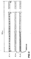
- FIG. 2 shows the payload distribution on the basis of an example with a payload of 2048 kbit / s.
- SHDSL1 and SHDSL2 the signals / bit sequences on the relevant transmission line 1 and 2 - cf. Figure 1 - shown.
- the "sum signal" to be formed via the application interface is denoted by ⁇ 1 , ⁇ 1 in FIG.
- the signals denoted below by ⁇ 2 , ⁇ 2 in FIG. 2 are the two parts in 2-wire operation at the respective interfaces. In the present case with two lines, this sum signal has twice the bandwidth on. This sum signal is not shown correctly in FIG. 2 with respect to the time axis.
- this frame information includes a fixed pattern defined by bits 1 to 6, 11, 16, 21 and 26, see Table 1.
- the key information Key-Inf is also checked. The key information Key-Inf must not change and the value must be valid. The state diagram for synchronization can be seen in FIG. If an incorrect AIMSS frame is detected twice, the synchronization is lost.
- a check sum is transmitted. This checksum is based on the CRC-4 algorithm with the polynomial x 4 + x + 1 calculated. The checksum is always calculated over the two halves of the AIMSS subframe, which means that in an AIMSS frame it has two CRC-4 blocks. Based on this checksum, the quality of the AIMSS signal can be checked. As a result, it is possible to conclude a bit error rate over a longer period, for example 1 s.
- the RX alarm information of all received alarms is ORed.
- q4 number (0 or 1) of the partial flow;
- Standing 4 lines available can be driven in 4-Wire Protection.
- 4-wire operation the data stream from the user interface 12 is split into two sub-streams.
- n Protection The details of a system with 1: 1 or 1: n Protection must be set via the configuration.
- a failed line is replaced directly by a replacement line. All SHDSL transmission links are started up, but the replacement path is only released when the useful path fails. There is a replacement path available. The substitute path can be used to drive low priority traffic.
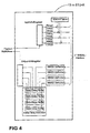
- FIG. 4 shows the block diagram of a possible AIMSS multiplexer 13.
- four SHDSL transmission links 1 are provided in comparison with the representation in FIG.
- the structure of the AIMSS multiplexer 13 changes nothing compared to an arrangement with two SHDSL transmission links 1.
- Seroes G Transmission systems and media, digital systems and networks
Landscapes
- Engineering & Computer Science (AREA)
- Computer Networks & Wireless Communication (AREA)
- Signal Processing (AREA)
- Computer Security & Cryptography (AREA)
- Communication Control (AREA)
- Time-Division Multiplex Systems (AREA)
Abstract
Description
- Die vorliegende Erfindung betrifft ein Verfahren zur SHDSL-Übertragung mit mehreren SHDSL-Leitungen unter Erfüllung von Qualitätskriterien gemäss dem Oberbegriff des Patentanspruches 1 und einen SHDSL-Multiplexer zur Durchführung des Verfahrens gemäss dem Patentanspruch 10.
- Im Folgenden werden anstelle einer deutschen Nichtfachsprache die englischsprachige Nomenklatur und Akronyme aus der Standardisierung der Organisationen ITU-T und ETSI benutzt, wie z.B.
«Path Interchange» Vertauschung zweier Aderpaare; «DLL» Digital Local Line; «Payload» Nutzlast, Nutzinformation; usw. - Durch die Verwendung standardisierter Begriffe und Akronyme lassen sich Unklarheiten vermeiden. Eine Liste der verwendeten Akronyme, Abkürzungen und Begriffe am Schluss dieses Dokumentes bildet einen integralen Bestandteil dieser Schrift.
- SHDSL-Normen definieren einen n-Wire oder einen M-Pair Mode, wobei für n und M gilt:

- Dieser standardisierte n-Wire Mode hat einige Einschränkungen. Namentlich fehlen die Eigenschaften Resilience, Path Interchange und Protection-Features. Diese Eigenschaften - synonym Qualitätskriterien genannt - sind nachstehend definiert.
- Ausfallsicherheit, wobei bei einem Ausfall die betreffende Übertragungsstrecke mit reduzierter Bandbreite weiterläuft, in der Fachsprache wird dies «gracefull degration» genannt.
- Pfadvertauschung, Vertauschung zweier oder mehrerer Aderpaare bei der Installation, z.B. durch den Betreiber der Strecke. Anstelle von «Path Interchange» wird dieses Qualitätsmerkmal zuweilen präziser «Path Interchange Compensation» genannt.
- Gemäss ITU-T G.991.2 [1] p. 28 ist im optionalen M-Pair Mode mit M >= 2 ein Differential delay buffer definiert, um pro Aderpaar aufgetretene Verzögerungen zu kompensieren. Diese Verzögerungen sind bedingt durch Aderpaar-individuelle Charakteristika wie Länge, Drahtdurchmesser, Isolation, usw.
- Protection bedeuet: Umschalten auf im voraus zugewiesene Kapazität zwischen zwei Knoten, um eine ausgefallene oder gestörte Übertragung zu schützen.
- Es ist nur ein Framer/Mapper in Betrieb. Hier ist der Nutzleitung die zweite SHDSL-Line als Ersatzleitung zugeordnet. Das Signal liegt an beiden Leitungen an. Wenn eine der Leitungen ausfällt oder Probleme macht, schalten die empfangsseitigen Netzelemente auf die Ersatzleitung. Der Vorteil des 1+1 Protection Mode ist, dass die Umschaltzeit sehr schnell ist und dass die Konfiguration einfach ist.
- Ausgefallene Leitungen werden direkt (1:1) durch Ersatzleitungen ersetzt. Es werden beide SHDSL-Leitungen hochgefahren. Der Ersatzpfad ist erst dann freigeschaltet, wenn sowohl sende- als auch empfangsseitig umgeschaltet wurde. Solange der Netzbetrieb störungsfrei abläuft, kann der Ersatzkanal auch für die Übertragung von Daten geringer Priorität genutzt werden. Dieser Mode kann auch bei vierfach SHDSL-Systemen zwei zum 1:3-Protection Mode ausgebaut werden.
- Der vorliegenden Erfindung liegt nun ausgehend von den Festlegungen gemäss ITU-T G.991.2 [1] die Aufgabe zugrunde, ein Verfahren zur SHDSL-Übertragung mit mehreren SHDSL-Leitungen unter Erfüllung von Qualitätskriterien anzugeben, das die vorgenannten Nachteile behebt und insbesondere die Qualitätskriterien Resilience, Path Interchange, und Protection-Feature's ermöglicht.
- Diese Aufgabe wird für ein Verfahren der eingangs genannten Art durch die im Patentanspruch 1 angegebenen Merkmale gelöst.
- Durch die erfindungsgemässe Lösung, wonach
«für die Anwendungsschnittstelle in jeder SHDSL Transceiver Unit ein zusätzliches Bit der Nutzdaten vorgesehen ist, wobei aus der Einfügung des zusätzlichen Bit im festen Zeitraster ein Subframe gebildet wird, der die Qualitätskriterien und Signalisierung enthält»,
ist ein Verfahren geschaffen, dass unabhängig von der Übertragung auf den Leitungen ist, da die Nutzdaten (payload) einfach in Richtung leere Bits verschoben werden. Vorteilhafterweise wird ein Synchronisationswort mit einem festen Muster dazu benutzt, um den Anfang der Rahmenstruktur zu erkennen. - Dieses zusätzliche Bit kann vorteilhafterweise - wegen einer einfacheren Implementierung - am Anfang der Nutzdaten eingefügt werden, die vorgeschlagene Lösung ist jedoch unabhängig von der Lage dieses Bits.
- Vorteilhafte Ausgestaltungen der Erfindung sind in weiteren Ansprüchen angegeben.
- Ein Ausführungsbeispiel mit verschiedenen Ausprägungen der Erfindung wird nachfolgend anhand der Zeichnung näher erläutert. Dabei zeigen:
- Figur 1
- Ausführungsbeispiel einer SHDSL-Übertragungsstrecke gemäss der vorliegenden Erfindung;
- Figur 2
- Rahmenstruktur für das Verfahren gemäss der vorliegenden Erfindung;
- Figur 3
- Zustandsdiagramm für die Synchronisierung.
- Figur 4
- Blockschaltbild einer möglichen AIMSS-Realisierung.
- In Figur 1 sind die funktionalen Komponeten für eine SHDSL-Übertragungsstrecke gemäss einer bevorzugten Ausführungsform der vorliegenden Erfindung gezeigt. Diese Bezeichnung, insbesondere die interne Schnittstelle α ist dem Dokument ITU-T G.991.2 [1], Figur 4-1/G.991.2 entnommen. Die in Figur 1 angegebenen Anwenderschnittstellen A, B, C und D sowie die Amtsschnittstellen E, F, G und H sind rein beispielhaft. An dieser Stelle wird noch auf den begrifflichen Unterschied zwischen Anwenderschnittstelle A, B, C und D und der (internen) Anwendungsschnittstellen α, β iSv von hingewiesen ITU-T G.991.2 [1].
- An der Anwendungsschnittstelle α2, β2 ist ein zusätzliches Bit vorgesehen. Dieses Bit wird im Rahmen dieser Schrift AIMSS-Bit genannt. Gemäss der Rahmenstruktur bzw. der Timeslots TS ist dies also ein Bit, dass alle 125µs übertragen wird. Für dieses Bit muss die SHDSL-Payload Bitrate um 8 kBit/s erhöht werden. Dies wird erreicht in dem man ein zusätzliches Z-Bit überträgt. Bei einer SHDSL-Payloadbitrate von 89 Zeitschlitzen (5696 kBit/s) ist dies nicht mehr möglich da dies nach Standard die maximale SHDSL-Payloadbitrate ist. In diesem Fall wird das AIMSS-Bit dem Payload gestohlen. Die maximale Payloadbitrate eines solchen zwei Aderpaar-Systems beträgt 11376 kBit/s. Wenn das AIMSS-Bit dem Payload gestohlen wird ist die Payload-Datenrate nicht mehr durch 64 kBit/s teilbar. Diese «Robbed-Bit»-Technik ist deshalb nur bei Packet-Interfaces, z.B. Ethernet, auf der Teilnehmerseite erlaubt. Die Wahl zwischen Z-Bit und Robbed-Bit bei einer SHDSL-Bitrate kleiner 5696 kBit/s ist der jeweiligen System-Implementierung überlassen.
- Aus diesem Bit wird ein Signal - im folgenden AIMSS-Frame genannt - mit einer Periodizität von 48 Bit gebildet. Diese Bits sind von 0 bis 47 nummeriert. Der so gebildete AIMSS-Frame hat dadurch eine Periodizität von 6 ms. Von diesen 48 Bits werden 10 Bits mit einem fixen Muster belegt. Dieses Muster wird zur Synchronisation benutzt. Das Muster ist so aufgebaut, dass es keine Falschsynchronisation geben kann solange keine Übertragungsfehler auftreten.
- Dieser AIMSS-Frame wird auch für den Delta-Delay Ausgleich benützt. Das maximale Delta-Delay, das sich ausgleichen lässt ist 3ms.
- In den 38 Bits - also 48 Bit minus die 10 Snychronisationsbits, nämlich 1 bis 6, 11, 16, 21 und 26 - welche nicht für die Synchronisierung benützt werden, wird die Nutzinformation für den AIMSS-Frame übertragen.
- Im Mehraderpaar-Betrieb wird die Payload Byte-interleafed übertragen. Die Bitrate des Signals vom AIMSS zum SHDSL-Tranceiver ist dabei die Hälfte wie die Bitrate vom Framer/Mapper zum AIMSS-Block 13.
- Figur 2 zeigt die Payload Aufteilung anhand eines Beispiels mit einem Payload von 2048 kBit/s. Mit SHDSL1 und SHDSL2 sind die Signale/Bitfolgen auf der betreffenden Übertragungsleitung 1 und 2 - vgl. Figur 1 - dargestellt. Das über die Anwendungsschnittstelle zu bildende «Summensignal» ist in Figur 2 mit β1,α1 bezeichnet. Die in Figur 2 unten mit β2,α2 Bezeichneten Signale sind die beiden Teile im 2-Aderbetrieb an den betreffenden Schnittstellen. Im vorliegenden Fall mit zwei Leitungen weist dieses Summensignal die doppelte Bandbreite auf. Dieses Summensignal ist in der Figur 2 bezüglich der Zeitachse nicht korrekt dargestellt.
- Damit der AIMSS-Frame besser gezeigt werden kann wird dieser in der nachfolgenden Tabelle in zwei Hälften mit je 24 Bits dargestellt. Diese beiden Hälften repräsentieren einen AIMSS-Subframe. Der CRC4 wird getrennt über die vorgenannten Hälften des AIMSS-Subframes gerechnet.
Tab. 1 Belegung eines AIMSS-Frames von 48 Bit Länge. 1 2 3 4 5 6 7 8 9 10 11 12 13 14 15 16 17 18 19 20 21 22 23 24 0 0 0 0 0 1 c1 c2 c3 c4 1 p1 p2 p3 p4 1 a1 a2 a3 a4 1 q1 q2 q3 25 26 27 28 29 30 31 32 33 34 35 36 37 38 39 40 41 42 43 44 45 46 47 48 q4 1 t1 t2 t3 t4 c1 c2 c3 c4 v1 v2 v3 v4 w1 w2 zb s1 s2 s3 s4 s5 s6 s7 - Die in der vorstehenden Tabelle 1 aufgeführten Bezeichner haben folgende Bedeutung:
- c1 - c4=
- CRC4 Info
- p1 - p4 =
- Path Identifier
- a1 - a4 =
- Alarm-Information
- q1 - q4 =
- QoS-Information, d.h. Protection und Resilience
- t1 - t4 =
- TX-Information
- v1 - v2 =
- Alarm Information am User-Interface
- w1 - w2 =
- Wire-Information
- zb =
- AIMSS-Frame in Z-Bit
- s1 - s7 =
- Path Speed Information, Wertebereich 3 bis 89
- Diese Informationen sind im AIMSS-Block 13 konfigurierbar. Wichtige Informationsbits aus dem ATMSS-Frame werden zu Key-Informationen Key-Inf zusammengefasst. Key-Information Key-Inf sind z.B.
- Path-Identifier p1 - p4,
- Wire-Information w1 - w2,
- z-Bit zb und
- Path Speed s1 - s7.
- Wird zweimal hintereinander die Rahmeninformation korrekt erkannt und sind Key-Informationen konstant, gilt die Synchronisierung als erfolgreich. Diese Rahmeninformation beinhaltet also ein festes Muster, das durch die Bits 1 bis 6, 11, 16, 21 und 26 definiert ist, siehe dazu die Tabelle 1. Zusätzlich zur Rahmeninformation werden noch die Key-Informationen Key-Inf überprüft. Die Key-Information Key-Inf darf nicht ändern und der Wert muss gültig sein. Das Zustandsdiagramm zur Synchronisierung ist der Figur 3 zu entnehmen. Wird zweimal ein nicht korrekter AIMSS-Frame festgestellt, gilt die Synchronisation als verloren.
- In den Bits 7 bis 10 und 31 bis 34 gemäss der Tabelle 1 wird je eine Checksumme übertragen. Diese Checksumme wird nach dem CRC-4 Algorithmus mit dem Polynom

- In den Bits 12 bis 15 wird der Path Identifier übertragen. Durch den Path Identifier kann der Pfad eineindeutig identifiziert werden. Dadurch kann eine Pfad Vertauschung aufgelöst werden. Die Codierung kann wie folgt vorgesehen sein:
- p4...p1 = «0001» entspricht Pfad 1 (Tx U1)
- p4...p1 = «0010» entspricht Pfad 2 (Tx U2)
- p4...p1 = «0100» entspricht Pfad 3 (Tx U3)
- p4...p1 = «1000» entspricht Pfad 4 (Tx U4)
- In den Bits 17 bis 20 wird die Alarm Information des AIMSS Signals übertragen.
Eine «1» bedeutet, für diesen Pfad ist ein Alarm aufgetreten; die Codierung ist wie folgt: - a1 = Alarm auf Pfad 1 (Tx U1)
- a2 = Alarm auf Pfad 2 (Tx U2)
- a3 = Alarm auf Pfad 3 (Tx U3)
- a4 = Alarm auf Pfad 4 (Tx U4)
- Die RX-Alarm Information aller empfangenen Alarme wird ODERverknüpft.
- Für die Sicherstellung von verschiedenen Diensten kann man im AIMSS Protection oder Resilience aktivieren:
- q2...q1 = «00» entspricht keine Protection → «n Wire-Mode»
- q2...q1 = «01» entspricht Resilience Mode
- q2...q1 = «10» entspricht 1+1 Protection
- q2...q1 = «11» entspricht 1:1 oder 1:n Protection
- q4...q3 = Nummer (0-3) des Datenstrom bei 1:1 oder 1:n Protection
- q3 = Nummer (0 oder 1) des Datenstrom bei 1:1
- q4 = Nummer (0 oder 1) des Teilstroms; zur Erläuterung:
Stehen 4 Lines zur Verfügung kann im 4-Wire Protection gefahren werden. Beim 4-Wire Betrieb wird der Datenstrom vom User-Interface 12 in zwei Teilströme aufgespalten. - Die Einzelheiten eines Systems mit 1:1 oder 1:n Protection müssen über die Konfiguration eingestellt werden.
- Die TX-Information zeigt an, welche Systeme für TX benützt werden. Diese Information ist vor allem im Zusammenhang dem Resilience-Mode oder einem Protection-Mode notwendig. Werden im Resilience-Mode nicht alle Lines die auf dem fernen Gerät mit Payload belegt, ist das ganze System fehlerhaft. Sind STU-C und STU-R nicht einig, welche SHDSL-Line für den Payload benutzt wird, funktioniert dies ohne die TX-Information nicht. Die TX-Information dient zur Identifikation der SHDSL-Strecke, die tatsächlich Payloads beinhaltet. Beim n-Wire Mode ohne Resilience ist das nicht notwendig, denn dort hat ein Fehler einen Totalausfall zur Folge.
- t1 =
- U1 wird für Payload benützt.
- t2 =
- U2 wird für Payload benützt.
- t3 =
- U3 wird für Payload benützt.
- t4 =
- U4 wird für Payload benützt.
- Der englische Ausdruck User-Interface heisst Anwender/Vermittlungsschnittstelle. In dieser Information wird mitgeteilt, welche Anwender-/Vermittlungsschnittstellen fehlerhaft sind. Im folgenden ist diese Anwender-/Vermittlungsschnittstelle mit T/V bezeichnet (Teilnehmer/Vermittlung). Diese Information wird bei allem bei 1:1 und 1:n Protection benötigt.
- v1 =
- Alarm auf der T/V-Schnittstelle zu Pfad 1/Datenstrom 1
- v2 =
- Alarm auf der T/V-Schnittstelle zu Pfad 2/Datenstrom 2
- v3 =
- Alarm auf der T/V-Schnittstelle zu Pfad 3/Datenstrom 3
- v4 =
- Alarm auf der T/V-Schnittstelle zu Pfad 4/Datenstrom 4
- Zeigt wie viele Aderpaare ein komplettes Inverse Multiplexer Signal ergeben.
- w2...w1 =
- "00" 2-Wire Operation (1 Aderpaar)
- w2...w1 =
- "01" 4-Wire Operation (2 Aderpaare)
- w2...w1=
- "10" 8-Wire Operation (4 Aderpaare)
- Eine ausgefallene Leitung wird direkt durch eine Ersatzleitung ersetzt. Es werden alle SHDSL-Übertragungsstrecken hochgefahren, aber der Ersatzpfad wird erst dann freigeschaltet, wenn der Nutzpfad ausfällt. Es steht ein Ersatzpfad zur Verfügung. Auf dem Ersatzpfad kann «Low Priority Traffic» gefahren werden.
- Dieser Mode wird 2-Wire Mode genannt da jede einzelne Leitung im 2-Wire Mode ist. Auf der Sendeseite wird durch den Remote Alarm-Status bestimmt wie viele Datenströme gesendet werden können. Es werden immer die Datenströme gesendet welche von der Konfiguration die höchste Priorität zugewiesen bekommen haben. Haben zwei Datenströme die gleiche Priorität wird der Sendestrom mit der niedrigsten Nummer ausgewählt wenn dadurch nicht ein Sendestrom mit der gleichen Priorität unterbrochen wird. Ein Sendestrom der an der Anwender-/Vermittlungsschnittstelle einen dringenden Alarm hat wird automatisch temporär der niedrigsten Priorität zugewiesen:
- p <= path(Un)
- t1 <= not rx_a1
- t2 <= not rx_a2
- t3 <= not rx_a3 when prot_n > 1 else '0';
- t4 <= not rx_a4 when prot_n > 2 else '0';
- a1 <= not AIMSS_p1_ok;
- a2 <= not AIMSS_p2_ok;
- a3 <= not AIMSS_p3_ok when prot_n > 1 else '0';
- a4 <= not AIMSS_p4_ok when prot_n > 2 else '0';
- y1 <= alarm_V_IF(Datastream1);
- y2 <= alarm_V_IF(Datastream2);
- y3 <= alarm_V_IF(Datastream3) when prot_n > 1 else '0';
- y4 <= alarm_V_IF(Datastream4) when prot_n > 2 else '0';
- q(2 downto 0) <= "11"
- q(4 downto 3) <= Nummer (Datastream);
- w <= "01";
- zb <= true_eth ;
-
- true_eth ist '1' when LT und NT ein
- aktives ETH-IF haben
- s <= n
-
- n ist die konfigurierte Geschwindigkeit
- vom Framer/Mapper
- Dieses System wird 4-Wire Mode genannt da die SHDSL-Leitungen eines 4-Wire-Systems mit 1:1 Protection gefahren werden, sind, das heisst es werden 4 SHDSL-Leitungen gebraucht. Es werden immer die Inverse Multiplexer Teil-Datenströme gesendet welche von der Konfiguration die höchste Priorität zugewiesen bekommen haben:
- p <= path (Un)
- t1 <= not rx_a1
- t2 <= not rx_a2
- t3 <= not rx_a3;
- t4 <= not rx_a4;
- a1 <= not AIMSS_p1_ok;
- a2 <= not AIMSS_p2_ok;
- a3 <= not AIMSS_p3_ok;
- a4 <= not AIMSS_p4_ok;
- y1 <= alarm_V_IF(Datastream1)
- y2 <= alarm_V_IF(Datastream2)
- y3 <= '0';
- y4 <= '0';
- q(2 downto 1) <= "11"
- q(3) <= Nummer(Datastream);
- q(4) <= Teilstrom;
- w <= "01";
- zb <= true_eth;
-
- true_eth ist '1' when LT und NT ein
- aktives ETH-IF haben
- s <= n
-
- n ist die konfigurierte Geschwindigkeit
- vom Framer/Mapper
- Figur 4 zeigt das Blockschaltbild eines möglichen AIMSS-Multiplexers 13. Dabei sind gegenüber der Darstellung in Figur 1 vier SHDSL-Übertragungsstrecken 1 vorgesehen. An der Struktur des AIMSS-Multiplexers 13 ändert sich dabei nichts gegenüber einer Anordnung mit zwei SHDSL-Übertragungsstrecken 1.
- Die vorstehend genannten Angaben zur Ausführungsform mit 2 Aderpaaren kann modifiziert ebenfalls für eine Ausführungsform mit 4 Aderpaaren übertragen werden.
- Die vorstehenden Angaben zu den Qualitätskriterien im Frame AIMSS bzw. in den beiden Subframes AIMSS sind untereinander frei kombinierbar, so dass je nach Anforderung nicht alle Bits gemäss der Tabelle 1 benutzt werden müssen, sondern ggfauch noch für andere Zwecke zur Verfügung stehen.
- Liste der verwendeten Bezugszeichen Akronyme
- 1
- Erste SHDSL-Übertragungsstrecke mit einem Aderpaar oder als Zweidrahtleitung
- 2
- Zweite SHDSL-Übertragungsstrecke mit einem Aderpaar oder als Zweidrahtleitung
- 11
- SHDSL-Transceiver
- 12
- Framer Mapper, Rate Adaptation; User Interface
- 13
- AIMSS-Block, Advanced Inverse Multiplexer for SHDSL Systems AIMSS; entspricht dem Transmission Protocol-Specific TC-Layer TPS-TC
- α,β
- Schnittstelle zwischen PMS-TC und TPS-TC-Layers in an STU-C resp. STU-R
- α,α1,α2
- Anwendungsschnittstelle, Schnittstelle zwischen TPS-TC layer und einem Framer Mapper 12 in einer STU-C
- β,β1,β2
- Anwendungsschnittstelle, Schnittstelle zwischen TPS-TC layer und einem Framer Mapper 12 in einer STU-R
- A, B, C, D
- Anwenderschnittstelle wie G.703, Ethernet, X.21, V35, V.36
- E, F, G, H
- Amtsschnittstelle wie G.703, Ethernet, X.21, V35, V.36
- AIMSS
- Advanced Inverse Multiplexer for SHDSL Systems an der Anwendungsschnittstelle
- ETH, eth
- Ethernet
- n
- Anzahl Wire (Drähte)
- Sync
- Synchronisationswort aus einem Muster im AIMSS-Frame
-
- DLL
- Digital Local Loop
- ETSI
- European Telecommunications Standards Institute, Sophia Antipolis
- ITU-T
- International Telecommunication Union Telecommunication Standardization Sector of ITU
- PMS-TC
- Physical Medium-Specific TC-Layer
- SHDSL
- Symmetric single pair high bitrate Digital Subscriber Line, Acronym gemäss ETSI
- SHDSL
- Single-Pair High-Speed DSL, Acronym gemäss ITU-T
- STU
- SHDSL Transceiver Unit;
- STU-R
- STU at the remote end
- STU-C
- STU at the central office
- TPS-TC
- Transmission Protocol-Specific TC-Layer
- Seroes G: Transmission systems and media, digital systems and networks
- Digital sections and digital line system - Access networks
- Single-pair high-speed digital subscriber line (SHDSL) transceivers
Claims (10)
- Verfahren zur SHDSL-Übertragung mit mehreren SHDSL-Leitungen (1, 2) unter Erfüllung von Qualitätskriterien, wobei- durch die Leitungen (1, 2) sind zwei SHDSL Transceiver Units (STU-C, STU-R) verbunden,- auf jeder Leitung werden in einem festen Zeitraster in einer Rahmenstruktur Nutzdaten übertragen,- jede SHDSL Transceiver Unit (STU-C, STU-R) weist pro Leitung einen SHDSL-Transceiver (11) auf, der mit einem Framer Mapper (12) über eine Anwendungsschnittstelle (α,β) gekoppelt ist und im Framemapper (12) ein Summensignal aus den auf jeder Leitung (1, 2) übertragenen Nutzdaten gebildet wird;dadurch gekennzeichnet, dass
an der Anraendungsschnittstelle (α,β) in jeder SHDSL Transceiver Unit (STU-C, STU-R) ein zusätzliches Bit in den Nutzdaten vorgesehen ist, wobei aus der Einfügung des zusätzlichen Bit im festen Zeitraster ein Frame (AIMSS) gebildet wird, das die Qualitätskriterien enthält. - Verfahren nach Anspruch 1,
dadurch gekennzeichnet, dass
der Frame (AIMSS) zur Synchronisierung ein festes Muster enthält. - Verfahren nach Anspruch 2,
dadurch gekennzeichnet, dass
der Frame (AIMSS) durch 48 Bits gebildet wird, wobei das Muster durch vordefinierte Werte in den Bits 1 bis 6, 11, 16, 21 und 26 bestimmt ist. - Verfahren nach Anspruch 2 oder 3,
dadurch gekennzeichnet, dass
eine Synchronisierung dann als erfolgt gilt, wenn das Muster im Frame (AIMSS) nach spätestens zwei Vergleichen erkannt wird. - Verfahren nach einem der Ansprüche 1 bis 4,
dadurch gekennzeichnet, dass
der Frame (AIMSS) in zwei Subframe gegliedert ist, über die je eine CRC-Checksumme gebildet wird und in jedem Subframe abgelegt ist. - Verfahren nach einem der Ansprüche 1 bis 5,
dadurch gekennzeichnet, dass
im Frame (AIMSS) die SHDSL-Leitungen in codierter Form enthalten sind, um eine dadurch erkannte Pfadvertauschung zu korrigieren. - Verfahren nach einem der Ansprüche 1 bis 6,
dadurch gekennzeichnet, dass
der Framer (12) in jedem SHDSL Transceiver (STU-R, STU-C) eine packetvermittelte Übertragungsstrecke aufweist. - Verfahren nach einem der Ansprüche 1 bis 7,
dadurch gekennzeichnet, dass
im Frame (AIMSS) vier Bits (q1 , .. , q4) enthalten sind, mit denen die Qualitätskriterien Protection und Resilience abgebildet sind. - Verfahren nach Anspruch 8,
dadurch gekennzeichnet, dass
im Frame (AIMSS) die vier Bits (q1 , .. , q4) zusätzlich einen Wire Mode der SHDSL-Übertragungsstrecke (1, 2) definieren. - SHDSL Transceiver Unit (STU-C, STU-R) mit Mitteln zur Durchführung des Verfahrens nach einem der Ansprüch 1 bis 9.
Priority Applications (1)
| Application Number | Priority Date | Filing Date | Title |
|---|---|---|---|
| EP20060025417 EP1826934B1 (de) | 2006-12-08 | 2006-12-08 | Verfahren zur SHDSL-Übertragung unter Erfüllung von Qualitätskriterien |
Applications Claiming Priority (1)
| Application Number | Priority Date | Filing Date | Title |
|---|---|---|---|
| EP20060025417 EP1826934B1 (de) | 2006-12-08 | 2006-12-08 | Verfahren zur SHDSL-Übertragung unter Erfüllung von Qualitätskriterien |
Publications (2)
| Publication Number | Publication Date |
|---|---|
| EP1826934A1 true EP1826934A1 (de) | 2007-08-29 |
| EP1826934B1 EP1826934B1 (de) | 2014-03-19 |
Family
ID=37908350
Family Applications (1)
| Application Number | Title | Priority Date | Filing Date |
|---|---|---|---|
| EP20060025417 Not-in-force EP1826934B1 (de) | 2006-12-08 | 2006-12-08 | Verfahren zur SHDSL-Übertragung unter Erfüllung von Qualitätskriterien |
Country Status (1)
| Country | Link |
|---|---|
| EP (1) | EP1826934B1 (de) |
Citations (1)
| Publication number | Priority date | Publication date | Assignee | Title |
|---|---|---|---|---|
| US6965608B1 (en) * | 1998-06-30 | 2005-11-15 | Cisco Technology, Inc. | Method and apparatus for transmitting data in a public network |
-
2006
- 2006-12-08 EP EP20060025417 patent/EP1826934B1/de not_active Not-in-force
Patent Citations (1)
| Publication number | Priority date | Publication date | Assignee | Title |
|---|---|---|---|---|
| US6965608B1 (en) * | 1998-06-30 | 2005-11-15 | Cisco Technology, Inc. | Method and apparatus for transmitting data in a public network |
Non-Patent Citations (1)
| Title |
|---|
| ETSI TECHNICAL COMMITTEE TRANSMISSION AND MULTIPLEXING (TM): "Transmission and Multiplexing (TM); Access transmission system on metallic access cables; Symmetric single pair high bitrate Digital Subscriber Line (SDSL); ETSI TS 101 524 V1.3.1", JOURNAL ARTICLE, February 2005 (2005-02-01), ETSI STANDARDS, EUROPEAN TELECOMMUNICATIONS STANDARDS INSTITUTE, SOPHIA-ANTIPO, FR, pages 1 - 217, XP002430157, Retrieved from the Internet <URL:http://webapp.etsi.org/exchangefolders/ts_101524v01> [retrieved on 20070418] * |
Also Published As
| Publication number | Publication date |
|---|---|
| EP1826934B1 (de) | 2014-03-19 |
Similar Documents
| Publication | Publication Date | Title |
|---|---|---|
| EP0363499B1 (de) | Verfahren und Schaltungsanordnung zum Übertragen von Sprachsignalen in einem Breitband-Kommunikationsnetz | |
| DE69416849T2 (de) | Digitale übertragungsstrecke zum effizienten transport von gemischten paketklassen | |
| DE69113451T2 (de) | Digitales datenübertragungssystem. | |
| DE4290392C2 (de) | Funktelefon-Kommunikationssystem | |
| DE202008018451U1 (de) | Erneute Übertragung in Datenübertragungssystemen | |
| EP0118767A2 (de) | Verfahren für eine Fernmelde-, insbesondere Fernsprechnebenstellenanlage mit einem Datenübertragungsleitungssystem, insbesondere mit einem optischen Datenübertragungsleitungssystem | |
| DE102013226014B4 (de) | Ethernetmedienkonverter, der Hochgeschwindigkeitsdrahtloszugriffspunkte unterstützt | |
| EP0993712B1 (de) | Verfahren und anordnung zur codierung digitaler daten | |
| EP1826934B1 (de) | Verfahren zur SHDSL-Übertragung unter Erfüllung von Qualitätskriterien | |
| WO2020088999A1 (de) | Teilnehmerstation für ein serielles bussystem und verfahren zum senden einer nachricht in einem seriellen bussystem | |
| EP1397020B1 (de) | Anordnung zur Sprach- und Datenkommunikation über eine gemeinsame Teilnehmeranschlussleitung | |
| DE69932810T2 (de) | Reserveleitungen in einem telekommunikationsnetzwerk | |
| DE3328834C2 (de) | ||
| DE102013220606B4 (de) | Paketkapselungsverfahren für den Mehrfachdienstbetrieb von einem Verteilungspunkt | |
| US9013982B2 (en) | M-pair mode protection switching | |
| EP0475135B1 (de) | Übertragungssystem für Zubringernetze in Kommunikationsnetzen | |
| DE60211564T2 (de) | Selbstroutendes auf einen Sternkoppler basierendes Kommunikationsnetzwerk | |
| US6590870B1 (en) | Transmission of alternating delimiter code to achieve byte alignment when using in-band digital code sequences to remotely provision network interface device terminating local loop | |
| DE102020214536A1 (de) | Teilnehmerstation für ein serielles Bussystem und Verfahren zur Kommunikation in einem seriellen Bussystem | |
| EP1548992B1 (de) | System zur Aufrechterhaltung einer fehlerfreien Kommunikation in einem Datenbus | |
| DE2849348C2 (de) | ||
| DE4420710C2 (de) | Private automatische Nebenstellenanlage für ISDN | |
| DE10126569B4 (de) | Datenübertragungsnetz | |
| EP2282428B1 (de) | Verfahren und System zur Umschaltung von Pfaden | |
| WO2005096662A1 (de) | Verfahren zur bereitstellung der funktionalität einer exchange termination-einheit und einer line termination-einheit in einem kommunikationsnetzwerk |
Legal Events
| Date | Code | Title | Description |
|---|---|---|---|
| PUAI | Public reference made under article 153(3) epc to a published international application that has entered the european phase |
Free format text: ORIGINAL CODE: 0009012 |
|
| AK | Designated contracting states |
Kind code of ref document: A1 Designated state(s): AT BE BG CH CY CZ DE DK EE ES FI FR GB GR HU IE IS IT LI LT LU LV MC NL PL PT RO SE SI SK TR |
|
| AX | Request for extension of the european patent |
Extension state: AL BA HR MK YU |
|
| 17P | Request for examination filed |
Effective date: 20070914 |
|
| AKX | Designation fees paid |
Designated state(s): AT BE BG CH CY CZ DE DK EE ES FI FR GB GR HU IE IS IT LI LT LU LV MC NL PL PT RO SE SI SK TR |
|
| RAP1 | Party data changed (applicant data changed or rights of an application transferred) |
Owner name: ALBIS TECHNOLOGIES AG |
|
| 17Q | First examination report despatched |
Effective date: 20090930 |
|
| GRAP | Despatch of communication of intention to grant a patent |
Free format text: ORIGINAL CODE: EPIDOSNIGR1 |
|
| INTG | Intention to grant announced |
Effective date: 20130920 |
|
| GRAS | Grant fee paid |
Free format text: ORIGINAL CODE: EPIDOSNIGR3 |
|
| GRAA | (expected) grant |
Free format text: ORIGINAL CODE: 0009210 |
|
| AK | Designated contracting states |
Kind code of ref document: B1 Designated state(s): AT BE BG CH CY CZ DE DK EE ES FI FR GB GR HU IE IS IT LI LT LU LV MC NL PL PT RO SE SI SK TR |
|
| REG | Reference to a national code |
Ref country code: GB Ref legal event code: FG4D Free format text: NOT ENGLISH |
|
| REG | Reference to a national code |
Ref country code: DE Ref legal event code: R082 Ref document number: 502006013607 Country of ref document: DE Representative=s name: MUELLER - HOFFMANN & PARTNER PATENTANWAELTE, DE Ref country code: DE Ref legal event code: R082 Ref document number: 502006013607 Country of ref document: DE Representative=s name: MUELLER HOFFMANN & PARTNER PATENTANWAELTE MBB, DE |
|
| REG | Reference to a national code |
Ref country code: CH Ref legal event code: NV Representative=s name: HANSJOERG KLEY, CH Ref country code: CH Ref legal event code: EP |
|
| REG | Reference to a national code |
Ref country code: IE Ref legal event code: FG4D Free format text: LANGUAGE OF EP DOCUMENT: GERMAN |
|
| REG | Reference to a national code |
Ref country code: AT Ref legal event code: REF Ref document number: 658281 Country of ref document: AT Kind code of ref document: T Effective date: 20140415 |
|
| REG | Reference to a national code |
Ref country code: DE Ref legal event code: R096 Ref document number: 502006013607 Country of ref document: DE Effective date: 20140430 |
|
| REG | Reference to a national code |
Ref country code: NL Ref legal event code: T3 |
|
| PG25 | Lapsed in a contracting state [announced via postgrant information from national office to epo] |
Ref country code: LT Free format text: LAPSE BECAUSE OF FAILURE TO SUBMIT A TRANSLATION OF THE DESCRIPTION OR TO PAY THE FEE WITHIN THE PRESCRIBED TIME-LIMIT Effective date: 20140319 |
|
| REG | Reference to a national code |
Ref country code: LT Ref legal event code: MG4D |
|
| PG25 | Lapsed in a contracting state [announced via postgrant information from national office to epo] |
Ref country code: CY Free format text: LAPSE BECAUSE OF FAILURE TO SUBMIT A TRANSLATION OF THE DESCRIPTION OR TO PAY THE FEE WITHIN THE PRESCRIBED TIME-LIMIT Effective date: 20140319 Ref country code: SE Free format text: LAPSE BECAUSE OF FAILURE TO SUBMIT A TRANSLATION OF THE DESCRIPTION OR TO PAY THE FEE WITHIN THE PRESCRIBED TIME-LIMIT Effective date: 20140319 Ref country code: FI Free format text: LAPSE BECAUSE OF FAILURE TO SUBMIT A TRANSLATION OF THE DESCRIPTION OR TO PAY THE FEE WITHIN THE PRESCRIBED TIME-LIMIT Effective date: 20140319 |
|
| PG25 | Lapsed in a contracting state [announced via postgrant information from national office to epo] |
Ref country code: LV Free format text: LAPSE BECAUSE OF FAILURE TO SUBMIT A TRANSLATION OF THE DESCRIPTION OR TO PAY THE FEE WITHIN THE PRESCRIBED TIME-LIMIT Effective date: 20140319 |
|
| PG25 | Lapsed in a contracting state [announced via postgrant information from national office to epo] |
Ref country code: IS Free format text: LAPSE BECAUSE OF FAILURE TO SUBMIT A TRANSLATION OF THE DESCRIPTION OR TO PAY THE FEE WITHIN THE PRESCRIBED TIME-LIMIT Effective date: 20140719 Ref country code: CZ Free format text: LAPSE BECAUSE OF FAILURE TO SUBMIT A TRANSLATION OF THE DESCRIPTION OR TO PAY THE FEE WITHIN THE PRESCRIBED TIME-LIMIT Effective date: 20140319 Ref country code: RO Free format text: LAPSE BECAUSE OF FAILURE TO SUBMIT A TRANSLATION OF THE DESCRIPTION OR TO PAY THE FEE WITHIN THE PRESCRIBED TIME-LIMIT Effective date: 20140319 Ref country code: BG Free format text: LAPSE BECAUSE OF FAILURE TO SUBMIT A TRANSLATION OF THE DESCRIPTION OR TO PAY THE FEE WITHIN THE PRESCRIBED TIME-LIMIT Effective date: 20140619 Ref country code: EE Free format text: LAPSE BECAUSE OF FAILURE TO SUBMIT A TRANSLATION OF THE DESCRIPTION OR TO PAY THE FEE WITHIN THE PRESCRIBED TIME-LIMIT Effective date: 20140319 |
|
| PG25 | Lapsed in a contracting state [announced via postgrant information from national office to epo] |
Ref country code: SK Free format text: LAPSE BECAUSE OF FAILURE TO SUBMIT A TRANSLATION OF THE DESCRIPTION OR TO PAY THE FEE WITHIN THE PRESCRIBED TIME-LIMIT Effective date: 20140319 Ref country code: PL Free format text: LAPSE BECAUSE OF FAILURE TO SUBMIT A TRANSLATION OF THE DESCRIPTION OR TO PAY THE FEE WITHIN THE PRESCRIBED TIME-LIMIT Effective date: 20140319 Ref country code: ES Free format text: LAPSE BECAUSE OF FAILURE TO SUBMIT A TRANSLATION OF THE DESCRIPTION OR TO PAY THE FEE WITHIN THE PRESCRIBED TIME-LIMIT Effective date: 20140319 |
|
| REG | Reference to a national code |
Ref country code: DE Ref legal event code: R097 Ref document number: 502006013607 Country of ref document: DE |
|
| PG25 | Lapsed in a contracting state [announced via postgrant information from national office to epo] |
Ref country code: PT Free format text: LAPSE BECAUSE OF FAILURE TO SUBMIT A TRANSLATION OF THE DESCRIPTION OR TO PAY THE FEE WITHIN THE PRESCRIBED TIME-LIMIT Effective date: 20140721 |
|
| PLBE | No opposition filed within time limit |
Free format text: ORIGINAL CODE: 0009261 |
|
| STAA | Information on the status of an ep patent application or granted ep patent |
Free format text: STATUS: NO OPPOSITION FILED WITHIN TIME LIMIT |
|
| PG25 | Lapsed in a contracting state [announced via postgrant information from national office to epo] |
Ref country code: DK Free format text: LAPSE BECAUSE OF FAILURE TO SUBMIT A TRANSLATION OF THE DESCRIPTION OR TO PAY THE FEE WITHIN THE PRESCRIBED TIME-LIMIT Effective date: 20140319 |
|
| 26N | No opposition filed |
Effective date: 20141222 |
|
| REG | Reference to a national code |
Ref country code: DE Ref legal event code: R097 Ref document number: 502006013607 Country of ref document: DE Effective date: 20141222 |
|
| PG25 | Lapsed in a contracting state [announced via postgrant information from national office to epo] |
Ref country code: BE Free format text: LAPSE BECAUSE OF NON-PAYMENT OF DUE FEES Effective date: 20141231 |
|
| PG25 | Lapsed in a contracting state [announced via postgrant information from national office to epo] |
Ref country code: SI Free format text: LAPSE BECAUSE OF FAILURE TO SUBMIT A TRANSLATION OF THE DESCRIPTION OR TO PAY THE FEE WITHIN THE PRESCRIBED TIME-LIMIT Effective date: 20140319 Ref country code: LU Free format text: LAPSE BECAUSE OF FAILURE TO SUBMIT A TRANSLATION OF THE DESCRIPTION OR TO PAY THE FEE WITHIN THE PRESCRIBED TIME-LIMIT Effective date: 20141208 |
|
| GBPC | Gb: european patent ceased through non-payment of renewal fee |
Effective date: 20141208 |
|
| REG | Reference to a national code |
Ref country code: IE Ref legal event code: MM4A |
|
| PG25 | Lapsed in a contracting state [announced via postgrant information from national office to epo] |
Ref country code: GB Free format text: LAPSE BECAUSE OF NON-PAYMENT OF DUE FEES Effective date: 20141208 Ref country code: IE Free format text: LAPSE BECAUSE OF NON-PAYMENT OF DUE FEES Effective date: 20141208 |
|
| REG | Reference to a national code |
Ref country code: FR Ref legal event code: PLFP Year of fee payment: 10 |
|
| PG25 | Lapsed in a contracting state [announced via postgrant information from national office to epo] |
Ref country code: MC Free format text: LAPSE BECAUSE OF FAILURE TO SUBMIT A TRANSLATION OF THE DESCRIPTION OR TO PAY THE FEE WITHIN THE PRESCRIBED TIME-LIMIT Effective date: 20140319 |
|
| PG25 | Lapsed in a contracting state [announced via postgrant information from national office to epo] |
Ref country code: GR Free format text: LAPSE BECAUSE OF FAILURE TO SUBMIT A TRANSLATION OF THE DESCRIPTION OR TO PAY THE FEE WITHIN THE PRESCRIBED TIME-LIMIT Effective date: 20140620 |
|
| PG25 | Lapsed in a contracting state [announced via postgrant information from national office to epo] |
Ref country code: TR Free format text: LAPSE BECAUSE OF FAILURE TO SUBMIT A TRANSLATION OF THE DESCRIPTION OR TO PAY THE FEE WITHIN THE PRESCRIBED TIME-LIMIT Effective date: 20140319 Ref country code: HU Free format text: LAPSE BECAUSE OF FAILURE TO SUBMIT A TRANSLATION OF THE DESCRIPTION OR TO PAY THE FEE WITHIN THE PRESCRIBED TIME-LIMIT; INVALID AB INITIO Effective date: 20061208 |
|
| REG | Reference to a national code |
Ref country code: FR Ref legal event code: PLFP Year of fee payment: 11 |
|
| REG | Reference to a national code |
Ref country code: FR Ref legal event code: PLFP Year of fee payment: 12 |
|
| PGFP | Annual fee paid to national office [announced via postgrant information from national office to epo] |
Ref country code: NL Payment date: 20171219 Year of fee payment: 12 Ref country code: FR Payment date: 20171219 Year of fee payment: 12 |
|
| PGFP | Annual fee paid to national office [announced via postgrant information from national office to epo] |
Ref country code: IT Payment date: 20171218 Year of fee payment: 12 Ref country code: AT Payment date: 20171215 Year of fee payment: 12 Ref country code: CH Payment date: 20171221 Year of fee payment: 12 |
|
| PGFP | Annual fee paid to national office [announced via postgrant information from national office to epo] |
Ref country code: DE Payment date: 20171219 Year of fee payment: 12 |
|
| REG | Reference to a national code |
Ref country code: DE Ref legal event code: R119 Ref document number: 502006013607 Country of ref document: DE |
|
| REG | Reference to a national code |
Ref country code: CH Ref legal event code: PL |
|
| REG | Reference to a national code |
Ref country code: NL Ref legal event code: MM Effective date: 20190101 |
|
| REG | Reference to a national code |
Ref country code: AT Ref legal event code: MM01 Ref document number: 658281 Country of ref document: AT Kind code of ref document: T Effective date: 20181208 |
|
| PG25 | Lapsed in a contracting state [announced via postgrant information from national office to epo] |
Ref country code: NL Free format text: LAPSE BECAUSE OF NON-PAYMENT OF DUE FEES Effective date: 20190101 |
|
| PG25 | Lapsed in a contracting state [announced via postgrant information from national office to epo] |
Ref country code: IT Free format text: LAPSE BECAUSE OF NON-PAYMENT OF DUE FEES Effective date: 20181208 Ref country code: DE Free format text: LAPSE BECAUSE OF NON-PAYMENT OF DUE FEES Effective date: 20190702 Ref country code: FR Free format text: LAPSE BECAUSE OF NON-PAYMENT OF DUE FEES Effective date: 20181231 |
|
| PG25 | Lapsed in a contracting state [announced via postgrant information from national office to epo] |
Ref country code: AT Free format text: LAPSE BECAUSE OF NON-PAYMENT OF DUE FEES Effective date: 20181208 Ref country code: CH Free format text: LAPSE BECAUSE OF NON-PAYMENT OF DUE FEES Effective date: 20181231 Ref country code: LI Free format text: LAPSE BECAUSE OF NON-PAYMENT OF DUE FEES Effective date: 20181231 |