EP1826451A1 - Embout d'un témoin d'usure bifilaire destiné à être relié à une plaquette de frein de véhicule automobile - Google Patents
Embout d'un témoin d'usure bifilaire destiné à être relié à une plaquette de frein de véhicule automobile Download PDFInfo
- Publication number
- EP1826451A1 EP1826451A1 EP07103106A EP07103106A EP1826451A1 EP 1826451 A1 EP1826451 A1 EP 1826451A1 EP 07103106 A EP07103106 A EP 07103106A EP 07103106 A EP07103106 A EP 07103106A EP 1826451 A1 EP1826451 A1 EP 1826451A1
- Authority
- EP
- European Patent Office
- Prior art keywords
- notch
- tip
- piece according
- end piece
- cable
- Prior art date
- Legal status (The legal status is an assumption and is not a legal conclusion. Google has not performed a legal analysis and makes no representation as to the accuracy of the status listed.)
- Granted
Links
Images
Classifications
-
- F—MECHANICAL ENGINEERING; LIGHTING; HEATING; WEAPONS; BLASTING
- F16—ENGINEERING ELEMENTS AND UNITS; GENERAL MEASURES FOR PRODUCING AND MAINTAINING EFFECTIVE FUNCTIONING OF MACHINES OR INSTALLATIONS; THERMAL INSULATION IN GENERAL
- F16D—COUPLINGS FOR TRANSMITTING ROTATION; CLUTCHES; BRAKES
- F16D66/00—Arrangements for monitoring working conditions, e.g. wear, temperature
- F16D66/02—Apparatus for indicating wear
- F16D66/021—Apparatus for indicating wear using electrical detection or indication means
- F16D66/022—Apparatus for indicating wear using electrical detection or indication means indicating that a lining is worn to minimum allowable thickness
- F16D66/023—Apparatus for indicating wear using electrical detection or indication means indicating that a lining is worn to minimum allowable thickness directly sensing the position of braking members
- F16D66/024—Sensors mounted on braking members adapted to contact the brake disc or drum, e.g. wire loops severed on contact
Definitions
- the present invention relates to a tip of friction lining wear indicator of a brake pad of a motor vehicle.
- a brake pad wear indicator generally consists of an electrical cable held by a bit in the vicinity or in the friction lining, so as to reveal the crossing of a critical threshold of wear of the gasket and therefore the opening or closing of an electrical circuit.
- a tip of such a witness is known, which is a plastic part, usually made of thermosetting plastic material, comprising a guide channel of the sheathed cable.
- This tip comprises a U-shaped positioning groove which allows to embed the tip in a notch of the support plate carrying the friction liner, the edge of this notch being trapped in the groove.
- this tip is usually attached to the brake pad by gluing or with the aid of an outer part comprising resilient means of the spring type.
- a tip comprising a fixing mechanism formed by two elastically deformable wings of the tip, by a cable guide to wedge between the two wings and by a particular shape of the notch, namely a narrow neck, which holds the tip in the notch as the two elastic wings are held apart from each other by wedging the cable between them.
- Such an end has the advantage that its assembly to the support plate does not require any external input. However, it requires an intervention on the cable to wedge between the two wings after positioning of the tip and, especially, it requires a special conformation of the notch.
- the invention aims in particular to provide a tip that is simple to assemble a support plate with a simple U-notch, not necessarily having a narrow neck.
- the subject of the invention is a tip of a friction lining wear indicator of a brake pad of a motor vehicle, said tip comprising a U-shaped positioning groove which makes it possible to house it in a U-shaped notch of a support plate of said wafer, characterized in that said tip comprises, in its positioning groove, a flexible tongue with a radial displacement arranged to support, by springback against the edge of the notch when the nozzle is housed.
- the tip according to the invention is positioned and fixed to the support plate in a single operation.
- the flexible tongue extends substantially parallel to the direction of insertion of the tip into the notch and comprises, in this direction, a free end and an end connected to the remainder of the mouthpiece, the end connected with the tongue being intended to be in the vicinity of the bottom of the notch, while the free end is intended to be positioned in the vicinity of the neck of the notch.
- the flexible tongue exerts on the edge of the notch a greater support force during the insertion of the tip into the notch that during the extraction of the tip out of the notch, because the friction of the free end of the tongue on the edge of the notch, during these movements of the tip, generates on the tongue a rotation torque which accentuates its deformation in the direction of the insertion and which opposes on the contrary to its deformation in the direction of the extraction.
- the flexible tongue has, at its free end, a projection intended to bear on the edge of the notch.
- the tip comprises, in its positioning groove, an axially symmetrical lug of the projection.
- This lug bears against the edge of the notch opposite the projection, so as to concentrate the efforts resulting from the elastic return of the flexible tongue in two axially opposite point of the notch, which promotes an orientation of the resultant forces perpendicular to the edge of the notch and, therefore, a better efficiency of the tongue against the removal of the tip outside the notch.
- the contact surface arranged in the second positioning groove is advantageously constituted by a lug facing the free end of the tongue, thereby accentuating the force holding the endpiece in the opening.
- the tip may also include a guide channel for receiving a wear indicator cable, the guide channel having a mouth opening on an outer surface of the tip.
- the cable can be pre-assembled with a connector connecting it to the rest of the electrical wiring harness of the motor vehicle, before being placed on the endpiece.
- the endpiece comprises resilient retaining means of the cable integrally molded with the endpiece.
- the cable is thus maintained in the channel and does not leave it, even if it opens on the outer surface of the nozzle.
- these retaining means being manufactured simultaneously with the tip, obtaining them does not require an additional step in the method of manufacturing the tip.
- the tip is shaped, at least partially around the guide channel, a collar having two arms, the cable retaining means constituting a free end arm of the collar.
- the tip is made of a material or a mixture of materials belonging to the following list: PA (polyamide), PA6.6 (polyamide 6,6), PAA (polyarylamide), PPA (polyphthalamide) PAI (polyamide- imyde), PEEK (polyetheretherketone).
- PA polyamide
- PA6.6 polyamide 6,6
- PAA polyarylamide
- PPA polyphthalamide
- PAI polyamide- imyde
- PEEK polyetheretherketone
- tip tip 10 Support plate Support plate 12 Positioning groove Positioning groove 14 Guide channel Throat 16, 16 ' Guide channel Orifice 16 " Flexible tongue Flexible tongue 18 Linked end Linked end 19a Free end Free end 19b Cable retainers Elastic arm 20, 20 ' Projection of the free end Projection of the free end 21 ergot ergot 22 nick nick 24 Bottom of the notch Bottom of the notch 26 Edge of the notch A first side wall of the notch 28 Edge of the notch A second side wall of the notch, opposite the first wall 28 30
- the positioning groove 14 allows the correct positioning of the tip in the notch, by insertion in the axial direction of the tip and the notch.
- 16, 16 ' The grooves 16, 16 ' constitute a guide channel for a cable forming a loop. These grooves have a mouth opening out of the mouthpiece.
- 16 " The orifice 16 "arranged in the vicinity of the linked end of the tongue is also a part of the guide channel for the cable, which makes it possible to arrange the cable in the opening 24 so as to form a loop.
- the flexible tongue 18 makes it possible to retain the tip in the orifice, by applying a pressing force on the side wall 28 of the notch. It has elastic properties, since it is made of plastic.
- the tongue is arranged to extend parallel to a first side wall 28 of the notch, against which it rests.
- 19a The linked end 19a of the tongue is intended to be arranged at the bottom 26 of the notch and is connected to the bottom of the orifice by means of a bridge of material 30.
- 19b The free end 19b of the flexible tongue 18 has a projection forming a contact surface 21 with the first side wall 28 of the notch 24.
- 20, 20 ' The resilient arms 20, 20 'of the guide channels of the grooves 16, 16' deviate during the introduction of the cable and, thanks to their elastic properties due to the material of which they are composed, recover in position and prevent then the cable to leave the gorges 16-16 '.
- the lug 22 formed in the groove 14 opposite the free end 19b of the tongue 18, constitutes a contact surface with a second side wall 30 of the notch. In addition to its effort concentration function, this lug allows a precise adjustment of the overall dimensions of the cavity of the mold of manufacture of the tip, to adapt the latter to a particular dimension of notch.
- the tip is made of thermoplastic material, more particularly PA (polyamide), PA6.6 (polyamide 6,6), PAA (polyarylamide), PPA (polyphthalamide) PAI (polyamide-imide), PEEK (polyetheretherketone).
- PA polyamide
- PA6.6 polyamide 6,6
- PAA polyarylamide
- PPA polyphthalamide
- PAI polyamide-imide
- PEEK polyetheretherketone
Landscapes
- Engineering & Computer Science (AREA)
- General Engineering & Computer Science (AREA)
- Mechanical Engineering (AREA)
- Braking Arrangements (AREA)
- Valves And Accessory Devices For Braking Systems (AREA)
Abstract
Description
- La présente invention concerne un embout de témoin d'usure de garniture de friction d'une plaquette de frein d'un véhicule automobile.
- Un témoin d'usure de plaquette de frein est en général constitué d'un câble électrique maintenu à l'aide d'un embout, au voisinage ou dans la garniture de friction, de façon à révéler le franchissement d'un seuil critique d'usure de la garniture et, donc, l'ouverture ou la fermeture d'un circuit électrique.
- On connaît, dans l'état de la technique, un embout d'un tel témoin, qui est une pièce en matière plastique, en général en matière plastique thermodurcissable, comportant un canal de guidage du câble gainé.
- Cet embout comprend une rainure de positionnement en forme de U qui permet d'encastrer l'embout dans une encoche de la plaque-support portant la garniture de friction, le bord de cette encoche étant emprisonné dans la rainure.
- Une fois positionné dans l'encoche, cet embout est en général fixé à la plaquette de frein par collage ou à l'aide d'une pièce extérieure comprenant des moyens élastiques, du type ressort.
- Ces solutions de fixation de l'embout à la plaque-support présentent l'inconvénient que leur mise en oeuvre nécessite plusieurs opérations et l'apport d'une colle ou d'une pièce extérieure élastique.
- Pour éviter cet apport, on a également proposé, dans le document
FR2707719 - Un tel embout présente l'avantage que son assemblage à la plaque-support ne nécessite aucun apport extérieur. Toutefois, il requiert une intervention sur le câble pour le coincer entre les deux ailes après positionnement de l'embout et, surtout, il nécessite une conformation spéciale de l'encoche.
- L'invention a notamment pour but de fournir un embout qui soit simple à assembler à une plaque-support munie d'une simple encoche en U, n'ayant pas nécessairement un col resserré.
- A cet effet, l'invention a pour objet un embout d'un témoin d'usure de garniture de friction d'une plaquette de frein d'un véhicule automobile, ledit embout comportant une rainure de positionnement en U qui permet de le loger dans une encoche en U d'une plaque-support de ladite plaquette, caractérisé en ce que ledit embout comporte, dans sa rainure de positionnement, une languette flexible à débattement radial agencée pour prendre appui, par retour élastique, contre le bord de l'encoche lorsque l'embout y est logé.
- L'embout selon l'invention se positionne et se fixe à la plaque-support en une seule opération.
- Il ne nécessite l'apport d'aucune pièce supplémentaire pour sa fixation à la plaque-support et s'accommode d'une encoche en U de forme simple, sans nécessairement de col resserré, bien qu'un tel col soit aussi compatible avec l'embout selon l'invention.
- Optionnellement, la languette flexible s'étend sensiblement parallèlement à la direction d'insertion de l'embout dans l'encoche et comporte, selon cette direction, une extrémité libre et une extrémité liée au reste de l'embout, l'extrémité liée de la languette étant destinée à se trouver au voisinage du fond de l'encoche, tandis que l'extrémité libre est destinée à se positionner au voisinage du col de l'encoche.
- Grâce à cet agencement, la languette flexible exerce sur le bord de l'encoche une force d'appui plus grande lors de l'insertion de l'embout dans l'encoche que lors de l'extraction de l'embout hors de l'encoche, du fait que la friction de l'extrémité libre de la languette sur le bord de l'encoche, lors de ces mouvements de l'embout, engendre sur la languette un couple de rotation qui accentue sa déformation dans le sens de l'insertion et qui s'oppose au contraire à sa déformation dans le sens de l'extraction.
- En d'autres termes, il est plus aisé d'insérer l'embout dans l'encoche que de l'en extraire, même si l'encoche a une simple forme en U.
- Optionnellement, la languette flexible comporte, à son extrémité libre, une saillie destinée à prendre appui sur le bord de l'encoche.
- Dans un mode de réalisation particulier, l'embout comporte, dans sa rainure de positionnement, un ergot axialement symétrique de la saillie.
- Cet ergot prend appui contre le bord de l'encoche à l'opposé de la saillie, de manière à concentrer les efforts résultant du retour élastique de la languette flexible en deux point axialement opposés de l'encoche, ce qui favorise une orientation de la résultante des efforts perpendiculairement au bord de l'encoche et, par conséquent, une meilleure efficacité de la languette contre le retrait de l'embout en dehors de l'encoche.
- La surface de contact agencée dans la seconde rainure de positionnement est avantageusement constituée par un ergot en vis-à-vis avec l'extrémité libre de la languette, accentuant alors la force maintenant l'embout dans l'ouverture.
- L'embout peut également comporter un canal de guidage destiné à accueillir un câble du témoin d'usure, ce canal de guidage comportant une embouchure débouchant sur une surface extérieure de l'embout.
- Grâce à l'accès du canal de guidage à l'extérieur de l'embout, le câble peut être pré-assemblé avec un connecteur le reliant au reste du faisceau de câbles électriques du véhicule automobile, avant d'être placé sur l'embout.
- Cela permet de minimiser les étapes de montage spécifiques au témoin d'usure lors du montage du véhicule automobile.
- Avantageusement, l'embout comporte des moyens de retenue élastique du câble venus de moulage avec l'embout.
- Le câble est ainsi maintenu dans le canal et ne le quitte pas, même s'il débouche sur la surface extérieure de l'embout.
- Il faut noter que, ces moyens de retenue étant fabriqués simultanément à l'embout, leur obtention ne nécessite pas d'étape supplémentaire dans le procédé de fabrication de l'embout.
- Avantageusement, l'embout est conformé, au moins partiellement autour du canal de guidage, en un collier comportant deux bras, les moyens de retenue du câble constituant un bras d'extrémité libre de ce collier.
- Pour mettre le câble en position dans le canal de guidage, on écarte ce bras flexible, car composé de matériau thermoplastique, et une fois le câble mis en place dans le canal, le bras reprend sa position initiale, empêchant tout mouvement du câble vers l'extérieur du canal de guidage.
- Cela permet d'améliorer considérablement la fiabilité de l'embout, sans pour autant augmenter de façon significative son coût de fabrication.
- Optionnellement, l'embout est réalisé en un matériau ou en un mélange des matériaux appartenant à la liste suivante : PA (polyamide), PA6,6 (polyamide 6,6), PAA (polyarylamide), PPA (polyphtalamide) PAI (polyamide-imyde), PEEK (polyétheréthercetone).
- L'invention sera mieux comprise à la lecture de la description qui va suivre, donnée uniquement à titre d'exemple et faite en se référant aux dessins. Ces dessins représentent un mode de réalisation de l'invention, ne pouvant en aucun cas être considéré comme limitatif.
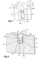
- La figure 1 représente une vue en perspective de face d'un l'embout selon un mode de réalisation de l'invention ;
- la figure 2 représente une vue en perspective de l'embout, coupé dans le plan médian des rainures de positionnement, assemblé à une plaquette de frein.
-
Des revendications de l'exemple référence sur les dessins Embout Embout 10 Plaque-support Plaque-support 12 Rainure de positionnement Rainure de positionnement 14 Canal de guidage Gorge 16, 16' Canal de guidage Orifice 16" Languette flexible Languette flexible 18 Extrémité liée Extrémité liée 19a Extrémité libre Extrémité libre 19b Moyens de retenue du câble Bras élastique 20, 20' Saillie de l'extrémité libre Saillie de l'extrémité libre 21 Ergot Ergot 22 Encoche Encoche 24 Fond de l'encoche Fond de l'encoche 26 Bord de l'encoche Une première paroi latérale de l'encoche 28 Bord de l'encoche Une seconde paroi latérale de l'encoche, opposée à la première paroi 28 30 -
Référence Explication 14 La rainure de positionnement 14 permet le positionnement correct de l'embout dans l'encoche, par insertion selon la direction axiale de l'embout et de l'encoche. 16, 16' Les gorges 16, 16' constituent un canal de guidage pour un câble formant une boucle. Ces gorges présentent une embouchure débouchant à l'extérieur de l'embout. 16" L'orifice 16" ménagé au voisinage de l'extrémité liée de la languette est également une partie du canal de guidage pour le câble. Il permet d'agencer le câble dans l'ouverture 24, de façon à former une boucle. 18 La languette flexible 18 permet de retenir l'embout dans l'orifice, en appliquant une force d'appui sur la paroi latérale 28 de l'encoche. Elle possède des propriétés élastiques, étant donné qu'elle est fabriquée en matière plastique. La languette est agencée pour s'étendre parallèlement à une première paroi latérale 28 de l'encoche, contre laquelle elle s'appuie. 19a L'extrémité liée 19a de la languette est destinée à être agencée au fond 26 de l'encoche et est reliée au fond de l'orifice à l'aide d'un pont de matière 30. 19b L'extrémité libre 19b de la languette flexible 18 comporte une saillie formant une surface de contact 21 avec la première paroi latérale 28 de l'encoche 24. 20, 20' Les bras élastiques 20, 20' des canaux de guidage des gorges 16, 16' s'écartent lors de la mise en place du câble puis, grâce à leurs propriétés élastiques due à la matière dont ils sont contitués, se remettent en position et empêchent alors le câble de quitter les gorges 16-16'. 22 L'ergot 22, ménagé dans la rainure 14 à l'opposé de l'extrémité libre 19b de la languette 18, constitue une surface de contact avec une seconde paroi latérale 30 de l'encoche. Outre sa fonction de concentration des efforts, cet ergot permet un réglage précis des dimensions hors tout de l'empreinte du moule de fabrication de l'embout, pour adapter ce dernier à une dimension particulière d'encoche. - L'embout est réalisé en matière thermoplastique, plus particulièrement en PA (polyamide), PA6,6 (polyamide 6,6), PAA (polyarylamide), PPA (polyphtalamide) PAI (polyamide-imyde), PEEK (polyétheréthercetone).
- La languette flexible 18 et les bras élastiques 20,20' sont venus du moulage avec l'embout 10.
Claims (8)
- Embout d'un témoin d'usure de garniture de friction d'une plaquette de frein d'un véhicule automobile, ledit embout (10) comportant une rainure de positionnement (14) en U qui permet de le loger dans une encoche en U (24) d'une plaque-support (12) de ladite plaquette, caractérisé en ce que ledit embout comporte, dans sa rainure de positionnement (14), une languette flexible (18) à débattement radial agencée pour prendre appui, par retour élastique, contre le bord (28) de l'encoche lorsque l'embout y est logé.
- Embout selon la revendication 1, dans lequel la languette flexible (18) s'étend sensiblement parallèlement à la direction d'insertion de l'embout dans l'encoche et comporte, selon cette direction, une extrémité libre (19b) et une extrémité liée (19a) au reste de l'embout, l'extrémité liée (18) de la languette étant destinée à se trouver au voisinage du fond de l'encoche, tandis que l'extrémité libre (19b) est destinée à se positionner au voisinage du col de l'encoche.
- Embout selon la revendication 2, dans lequel la languette flexible (18) comporte, à son extrémité libre (19b), une saillie (21) destinée à prendre appui sur le bord de l'encoche.
- Embout selon la revendication 3, dans lequel l'embout comporte, dans sa rainure de positionnement (14), un ergot (22) axialement symétrique de la saillie (21).
- Embout selon l'une quelconque des revendications précédentes, comportant un canal de guidage (16, 16') destiné à accueillir un câble du témoin d'usure, ce canal de guidage comportant une embouchure débouchant sur une surface extérieure de l'embout.
- Embout selon la revendication 5, dans lequel le canal de guidage comporte des moyens (20, 20') de retenue élastique du câble.
- Embout selon la revendication 6, conformé, au moins partiellement autour du canal de guidage, en un collier comportant deux bras, les moyens de retenue (20, 20') du câble constituant un bras d'extrémité libre de ce collier.
- Embout selon l'une quelconque des revendications précédentes, constitué en un matériau ou un mélange des matériaux appartenant à la liste suivante : PA (polyamide), PA6,6 (polyamide 6,6), PAA (polyarylamide), PPA (polyphtalamide) PAI (polyamide-imyde), PEEK (polyétheréthercetone).
Applications Claiming Priority (1)
| Application Number | Priority Date | Filing Date | Title |
|---|---|---|---|
| FR0601709A FR2897914B1 (fr) | 2006-02-27 | 2006-02-27 | Embout d'un temoin d'usure bifilaire destine a etre relie a une plaquette de frein de vehicule automobile |
Publications (2)
| Publication Number | Publication Date |
|---|---|
| EP1826451A1 true EP1826451A1 (fr) | 2007-08-29 |
| EP1826451B1 EP1826451B1 (fr) | 2009-01-21 |
Family
ID=37116240
Family Applications (1)
| Application Number | Title | Priority Date | Filing Date |
|---|---|---|---|
| EP07103106A Active EP1826451B1 (fr) | 2006-02-27 | 2007-02-27 | Embout d'un témoin d'usure bifilaire destiné à être relié à une plaquette de frein de véhicule automobile |
Country Status (5)
| Country | Link |
|---|---|
| EP (1) | EP1826451B1 (fr) |
| AT (1) | ATE421652T1 (fr) |
| DE (1) | DE602007000494D1 (fr) |
| ES (1) | ES2322920T3 (fr) |
| FR (1) | FR2897914B1 (fr) |
Cited By (3)
| Publication number | Priority date | Publication date | Assignee | Title |
|---|---|---|---|---|
| WO2009152946A1 (fr) * | 2008-05-30 | 2009-12-23 | Knorr-Bremse Systeme für Nutzfahrzeuge GmbH | Dispositif de détection d’usure d’une garniture de frein dans un frein à disque et garniture de frein pour frein à disque |
| CN113883190A (zh) * | 2020-07-03 | 2022-01-04 | 克诺尔轨道车辆系统有限公司 | 轨道车辆的闸瓦以及闸瓦装置 |
| CN114382810A (zh) * | 2020-10-06 | 2022-04-22 | 采埃孚商用车系统欧洲有限公司 | 用于识别盘式制动器的制动衬块的磨损的装置 |
Citations (5)
| Publication number | Priority date | Publication date | Assignee | Title |
|---|---|---|---|---|
| GB2115893A (en) * | 1982-03-04 | 1983-09-14 | Lucas Ind Plc | An alarm device for use in indicating the wear of friction linings on brake pads |
| DE4117423A1 (de) * | 1991-05-28 | 1992-12-03 | Porsche Ag | Verschleissanzeigevorrichtung fuer eine scheibenbremse |
| FR2707719A1 (fr) * | 1993-07-12 | 1995-01-20 | Plastic Omnium Cie | Embout pour témoin d'usure de garniture de friction, notamment de plaquette de frein. |
| EP0974767A2 (fr) * | 1998-07-22 | 2000-01-26 | Sumitomo Electric Industries, Ltd. | Témoin d'usure de patin de frein |
| EP1148267A2 (fr) * | 2000-04-21 | 2001-10-24 | Sumitomo Wiring Systems, Ltd. | Détecteur d'usure pour un élément de freinage |
-
2006
- 2006-02-27 FR FR0601709A patent/FR2897914B1/fr not_active Expired - Fee Related
-
2007
- 2007-02-27 EP EP07103106A patent/EP1826451B1/fr active Active
- 2007-02-27 AT AT07103106T patent/ATE421652T1/de not_active IP Right Cessation
- 2007-02-27 DE DE602007000494T patent/DE602007000494D1/de active Active
- 2007-02-27 ES ES07103106T patent/ES2322920T3/es active Active
Patent Citations (5)
| Publication number | Priority date | Publication date | Assignee | Title |
|---|---|---|---|---|
| GB2115893A (en) * | 1982-03-04 | 1983-09-14 | Lucas Ind Plc | An alarm device for use in indicating the wear of friction linings on brake pads |
| DE4117423A1 (de) * | 1991-05-28 | 1992-12-03 | Porsche Ag | Verschleissanzeigevorrichtung fuer eine scheibenbremse |
| FR2707719A1 (fr) * | 1993-07-12 | 1995-01-20 | Plastic Omnium Cie | Embout pour témoin d'usure de garniture de friction, notamment de plaquette de frein. |
| EP0974767A2 (fr) * | 1998-07-22 | 2000-01-26 | Sumitomo Electric Industries, Ltd. | Témoin d'usure de patin de frein |
| EP1148267A2 (fr) * | 2000-04-21 | 2001-10-24 | Sumitomo Wiring Systems, Ltd. | Détecteur d'usure pour un élément de freinage |
Cited By (3)
| Publication number | Priority date | Publication date | Assignee | Title |
|---|---|---|---|---|
| WO2009152946A1 (fr) * | 2008-05-30 | 2009-12-23 | Knorr-Bremse Systeme für Nutzfahrzeuge GmbH | Dispositif de détection d’usure d’une garniture de frein dans un frein à disque et garniture de frein pour frein à disque |
| CN113883190A (zh) * | 2020-07-03 | 2022-01-04 | 克诺尔轨道车辆系统有限公司 | 轨道车辆的闸瓦以及闸瓦装置 |
| CN114382810A (zh) * | 2020-10-06 | 2022-04-22 | 采埃孚商用车系统欧洲有限公司 | 用于识别盘式制动器的制动衬块的磨损的装置 |
Also Published As
| Publication number | Publication date |
|---|---|
| EP1826451B1 (fr) | 2009-01-21 |
| DE602007000494D1 (de) | 2009-03-12 |
| FR2897914A1 (fr) | 2007-08-31 |
| FR2897914B1 (fr) | 2008-05-30 |
| ES2322920T3 (es) | 2009-07-01 |
| ATE421652T1 (de) | 2009-02-15 |
Similar Documents
| Publication | Publication Date | Title |
|---|---|---|
| EP1703188B1 (fr) | Collier de maintien | |
| FR2852639A1 (fr) | Organe de jonction de panneaux a rondelle et broche | |
| FR2929662A1 (fr) | Systeme et procede de retenue d'aube de turbine. | |
| EP2007991B1 (fr) | Dispositif de serrage | |
| EP1826451B1 (fr) | Embout d'un témoin d'usure bifilaire destiné à être relié à une plaquette de frein de véhicule automobile | |
| EP1851835B1 (fr) | Contact electrique femelle a lames de contact ressort | |
| FR2725765A1 (fr) | Frein a disque a montage ameliore | |
| FR2930028A1 (fr) | Module de capteur de pression comprenant une plaque de circuits imprimes et une cellule de pression. | |
| EP2816691A1 (fr) | Dispositif amélioré de maintien d'au moins un élément longitudinal, de type faisceau de câbles ou tube sur un support | |
| EP1056969A1 (fr) | Raccord encliquetable pour conduit de fluide | |
| FR2934336A1 (fr) | Dispositif de pince a ecrou pouvant etre monte sur le bord d'un panneau ou analogue | |
| FR2922691A1 (fr) | Agrafe pour le maintien de cables ou faisceaux, notamment sur la caisse ou la carrosserie d'un vehicule automobile. | |
| EP2811222B1 (fr) | Luminaire encastrable | |
| CN100392265C (zh) | 包括用于与控制部件固定的装置的离合器释放止推轴承 | |
| EP2730487A1 (fr) | Organe de maintien de deux éléments de carrosserie de véhicule automobile l'un contre l'autre | |
| FR3002379A1 (fr) | Bobine munie d'un support pour un capteur | |
| FR2688040A1 (fr) | Dispositif de detection d'usure de garnitures de friction. | |
| FR3113694A1 (fr) | Curseur pour dispositif lève-vitre de véhicule | |
| EP2076645B1 (fr) | Bandeau pour ventouse electromagnetique | |
| FR2584476A1 (fr) | Raccord de conduit | |
| EP1445844B1 (fr) | Structure électrique comprenant un dispositif de fixation d'au moins un câble, et une installation de fermeture ou de protection solaire correspondante | |
| EP1721794B1 (fr) | Dispositif de fixation par enclenchement de deux pièces mécaniques | |
| EP2235303B1 (fr) | Rotor pour verrou et verrou associe | |
| FR2594912A1 (fr) | Commande mecanique a cable a reglage automatique | |
| FR2756979A3 (fr) | Moyen de fixation pour une piece d'un connecteur assurant une connexion electrique |
Legal Events
| Date | Code | Title | Description |
|---|---|---|---|
| PUAI | Public reference made under article 153(3) epc to a published international application that has entered the european phase |
Free format text: ORIGINAL CODE: 0009012 |
|
| AK | Designated contracting states |
Kind code of ref document: A1 Designated state(s): AT BE BG CH CY CZ DE DK EE ES FI FR GB GR HU IE IS IT LI LT LU LV MC NL PL PT RO SE SI SK TR |
|
| AX | Request for extension of the european patent |
Extension state: AL BA HR MK YU |
|
| RIN1 | Information on inventor provided before grant (corrected) |
Inventor name: DELVENNE, CORINNE Inventor name: AGNUS, BRUNO |
|
| 17P | Request for examination filed |
Effective date: 20080222 |
|
| AKX | Designation fees paid |
Designated state(s): AT BE BG CH CY CZ DE DK EE ES FI FR GB GR HU IE IS IT LI LT LU LV MC NL PL PT RO SE SI SK TR |
|
| GRAP | Despatch of communication of intention to grant a patent |
Free format text: ORIGINAL CODE: EPIDOSNIGR1 |
|
| RIN1 | Information on inventor provided before grant (corrected) |
Inventor name: AGNUS, BRUNO Inventor name: DELVENNE, CORINNE |
|
| GRAS | Grant fee paid |
Free format text: ORIGINAL CODE: EPIDOSNIGR3 |
|
| GRAA | (expected) grant |
Free format text: ORIGINAL CODE: 0009210 |
|
| AK | Designated contracting states |
Kind code of ref document: B1 Designated state(s): AT BE BG CH CY CZ DE DK EE ES FI FR GB GR HU IE IS IT LI LT LU LV MC NL PL PT RO SE SI SK TR |
|
| REG | Reference to a national code |
Ref country code: GB Ref legal event code: FG4D Free format text: NOT ENGLISH |
|
| REG | Reference to a national code |
Ref country code: CH Ref legal event code: EP |
|
| REG | Reference to a national code |
Ref country code: IE Ref legal event code: FG4D Free format text: LANGUAGE OF EP DOCUMENT: FRENCH |
|
| REF | Corresponds to: |
Ref document number: 602007000494 Country of ref document: DE Date of ref document: 20090312 Kind code of ref document: P |
|
| PG25 | Lapsed in a contracting state [announced via postgrant information from national office to epo] |
Ref country code: NL Free format text: LAPSE BECAUSE OF FAILURE TO SUBMIT A TRANSLATION OF THE DESCRIPTION OR TO PAY THE FEE WITHIN THE PRESCRIBED TIME-LIMIT Effective date: 20090121 |
|
| NLV1 | Nl: lapsed or annulled due to failure to fulfill the requirements of art. 29p and 29m of the patents act | ||
| REG | Reference to a national code |
Ref country code: ES Ref legal event code: FG2A Ref document number: 2322920 Country of ref document: ES Kind code of ref document: T3 |
|
| PG25 | Lapsed in a contracting state [announced via postgrant information from national office to epo] |
Ref country code: SI Free format text: LAPSE BECAUSE OF FAILURE TO SUBMIT A TRANSLATION OF THE DESCRIPTION OR TO PAY THE FEE WITHIN THE PRESCRIBED TIME-LIMIT Effective date: 20090121 Ref country code: LT Free format text: LAPSE BECAUSE OF FAILURE TO SUBMIT A TRANSLATION OF THE DESCRIPTION OR TO PAY THE FEE WITHIN THE PRESCRIBED TIME-LIMIT Effective date: 20090121 Ref country code: FI Free format text: LAPSE BECAUSE OF FAILURE TO SUBMIT A TRANSLATION OF THE DESCRIPTION OR TO PAY THE FEE WITHIN THE PRESCRIBED TIME-LIMIT Effective date: 20090121 |
|
| REG | Reference to a national code |
Ref country code: IE Ref legal event code: FD4D |
|
| BERE | Be: lapsed |
Owner name: CIE PLASTIC OMNIUM Effective date: 20090228 |
|
| PG25 | Lapsed in a contracting state [announced via postgrant information from national office to epo] |
Ref country code: AT Free format text: LAPSE BECAUSE OF FAILURE TO SUBMIT A TRANSLATION OF THE DESCRIPTION OR TO PAY THE FEE WITHIN THE PRESCRIBED TIME-LIMIT Effective date: 20090121 Ref country code: IS Free format text: LAPSE BECAUSE OF FAILURE TO SUBMIT A TRANSLATION OF THE DESCRIPTION OR TO PAY THE FEE WITHIN THE PRESCRIBED TIME-LIMIT Effective date: 20090521 Ref country code: PL Free format text: LAPSE BECAUSE OF FAILURE TO SUBMIT A TRANSLATION OF THE DESCRIPTION OR TO PAY THE FEE WITHIN THE PRESCRIBED TIME-LIMIT Effective date: 20090121 Ref country code: SE Free format text: LAPSE BECAUSE OF FAILURE TO SUBMIT A TRANSLATION OF THE DESCRIPTION OR TO PAY THE FEE WITHIN THE PRESCRIBED TIME-LIMIT Effective date: 20090421 Ref country code: PT Free format text: LAPSE BECAUSE OF FAILURE TO SUBMIT A TRANSLATION OF THE DESCRIPTION OR TO PAY THE FEE WITHIN THE PRESCRIBED TIME-LIMIT Effective date: 20090622 Ref country code: LV Free format text: LAPSE BECAUSE OF FAILURE TO SUBMIT A TRANSLATION OF THE DESCRIPTION OR TO PAY THE FEE WITHIN THE PRESCRIBED TIME-LIMIT Effective date: 20090121 |
|
| PG25 | Lapsed in a contracting state [announced via postgrant information from national office to epo] |
Ref country code: MC Free format text: LAPSE BECAUSE OF NON-PAYMENT OF DUE FEES Effective date: 20090228 |
|
| PG25 | Lapsed in a contracting state [announced via postgrant information from national office to epo] |
Ref country code: DK Free format text: LAPSE BECAUSE OF FAILURE TO SUBMIT A TRANSLATION OF THE DESCRIPTION OR TO PAY THE FEE WITHIN THE PRESCRIBED TIME-LIMIT Effective date: 20090121 Ref country code: IE Free format text: LAPSE BECAUSE OF FAILURE TO SUBMIT A TRANSLATION OF THE DESCRIPTION OR TO PAY THE FEE WITHIN THE PRESCRIBED TIME-LIMIT Effective date: 20090121 Ref country code: EE Free format text: LAPSE BECAUSE OF FAILURE TO SUBMIT A TRANSLATION OF THE DESCRIPTION OR TO PAY THE FEE WITHIN THE PRESCRIBED TIME-LIMIT Effective date: 20090121 Ref country code: CZ Free format text: LAPSE BECAUSE OF FAILURE TO SUBMIT A TRANSLATION OF THE DESCRIPTION OR TO PAY THE FEE WITHIN THE PRESCRIBED TIME-LIMIT Effective date: 20090121 |
|
| PLBE | No opposition filed within time limit |
Free format text: ORIGINAL CODE: 0009261 |
|
| STAA | Information on the status of an ep patent application or granted ep patent |
Free format text: STATUS: NO OPPOSITION FILED WITHIN TIME LIMIT |
|
| PG25 | Lapsed in a contracting state [announced via postgrant information from national office to epo] |
Ref country code: SK Free format text: LAPSE BECAUSE OF FAILURE TO SUBMIT A TRANSLATION OF THE DESCRIPTION OR TO PAY THE FEE WITHIN THE PRESCRIBED TIME-LIMIT Effective date: 20090121 Ref country code: RO Free format text: LAPSE BECAUSE OF FAILURE TO SUBMIT A TRANSLATION OF THE DESCRIPTION OR TO PAY THE FEE WITHIN THE PRESCRIBED TIME-LIMIT Effective date: 20090121 |
|
| 26N | No opposition filed |
Effective date: 20091022 |
|
| PG25 | Lapsed in a contracting state [announced via postgrant information from national office to epo] |
Ref country code: BG Free format text: LAPSE BECAUSE OF FAILURE TO SUBMIT A TRANSLATION OF THE DESCRIPTION OR TO PAY THE FEE WITHIN THE PRESCRIBED TIME-LIMIT Effective date: 20090421 |
|
| PG25 | Lapsed in a contracting state [announced via postgrant information from national office to epo] |
Ref country code: BE Free format text: LAPSE BECAUSE OF NON-PAYMENT OF DUE FEES Effective date: 20090228 |
|
| PG25 | Lapsed in a contracting state [announced via postgrant information from national office to epo] |
Ref country code: GR Free format text: LAPSE BECAUSE OF FAILURE TO SUBMIT A TRANSLATION OF THE DESCRIPTION OR TO PAY THE FEE WITHIN THE PRESCRIBED TIME-LIMIT Effective date: 20090422 |
|
| PG25 | Lapsed in a contracting state [announced via postgrant information from national office to epo] |
Ref country code: LU Free format text: LAPSE BECAUSE OF NON-PAYMENT OF DUE FEES Effective date: 20090227 |
|
| PGFP | Annual fee paid to national office [announced via postgrant information from national office to epo] |
Ref country code: IT Payment date: 20110228 Year of fee payment: 5 |
|
| PGRI | Patent reinstated in contracting state [announced from national office to epo] |
Ref country code: IT Effective date: 20110501 |
|
| PG25 | Lapsed in a contracting state [announced via postgrant information from national office to epo] |
Ref country code: HU Free format text: LAPSE BECAUSE OF FAILURE TO SUBMIT A TRANSLATION OF THE DESCRIPTION OR TO PAY THE FEE WITHIN THE PRESCRIBED TIME-LIMIT Effective date: 20090722 |
|
| PG25 | Lapsed in a contracting state [announced via postgrant information from national office to epo] |
Ref country code: CY Free format text: LAPSE BECAUSE OF FAILURE TO SUBMIT A TRANSLATION OF THE DESCRIPTION OR TO PAY THE FEE WITHIN THE PRESCRIBED TIME-LIMIT Effective date: 20090121 |
|
| REG | Reference to a national code |
Ref country code: CH Ref legal event code: PL |
|
| PG25 | Lapsed in a contracting state [announced via postgrant information from national office to epo] |
Ref country code: LI Free format text: LAPSE BECAUSE OF NON-PAYMENT OF DUE FEES Effective date: 20110228 Ref country code: CH Free format text: LAPSE BECAUSE OF NON-PAYMENT OF DUE FEES Effective date: 20110228 |
|
| PGFP | Annual fee paid to national office [announced via postgrant information from national office to epo] |
Ref country code: GB Payment date: 20120322 Year of fee payment: 6 |
|
| PG25 | Lapsed in a contracting state [announced via postgrant information from national office to epo] |
Ref country code: IT Free format text: LAPSE BECAUSE OF NON-PAYMENT OF DUE FEES Effective date: 20120227 |
|
| GBPC | Gb: european patent ceased through non-payment of renewal fee |
Effective date: 20130227 |
|
| PG25 | Lapsed in a contracting state [announced via postgrant information from national office to epo] |
Ref country code: GB Free format text: LAPSE BECAUSE OF NON-PAYMENT OF DUE FEES Effective date: 20130227 |
|
| PGFP | Annual fee paid to national office [announced via postgrant information from national office to epo] |
Ref country code: DE Payment date: 20140227 Year of fee payment: 8 |
|
| PGFP | Annual fee paid to national office [announced via postgrant information from national office to epo] |
Ref country code: TR Payment date: 20140225 Year of fee payment: 8 Ref country code: ES Payment date: 20140320 Year of fee payment: 8 |
|
| REG | Reference to a national code |
Ref country code: DE Ref legal event code: R119 Ref document number: 602007000494 Country of ref document: DE |
|
| PG25 | Lapsed in a contracting state [announced via postgrant information from national office to epo] |
Ref country code: DE Free format text: LAPSE BECAUSE OF NON-PAYMENT OF DUE FEES Effective date: 20150901 |
|
| REG | Reference to a national code |
Ref country code: FR Ref legal event code: PLFP Year of fee payment: 10 |
|
| REG | Reference to a national code |
Ref country code: FR Ref legal event code: PLFP Year of fee payment: 11 |
|
| PG25 | Lapsed in a contracting state [announced via postgrant information from national office to epo] |
Ref country code: ES Free format text: LAPSE BECAUSE OF NON-PAYMENT OF DUE FEES Effective date: 20150228 |
|
| PG25 | Lapsed in a contracting state [announced via postgrant information from national office to epo] |
Ref country code: TR Free format text: LAPSE BECAUSE OF NON-PAYMENT OF DUE FEES Effective date: 20150227 |
|
| REG | Reference to a national code |
Ref country code: FR Ref legal event code: PLFP Year of fee payment: 12 |
|
| REG | Reference to a national code |
Ref country code: ES Ref legal event code: FD2A Effective date: 20180710 |
|
| PGFP | Annual fee paid to national office [announced via postgrant information from national office to epo] |
Ref country code: FR Payment date: 20260227 Year of fee payment: 20 |