EP1826111A1 - Bicycle brake control device - Google Patents
Bicycle brake control device Download PDFInfo
- Publication number
- EP1826111A1 EP1826111A1 EP06003694A EP06003694A EP1826111A1 EP 1826111 A1 EP1826111 A1 EP 1826111A1 EP 06003694 A EP06003694 A EP 06003694A EP 06003694 A EP06003694 A EP 06003694A EP 1826111 A1 EP1826111 A1 EP 1826111A1
- Authority
- EP
- European Patent Office
- Prior art keywords
- brake lever
- support body
- control device
- brake
- pivot
- Prior art date
- Legal status (The legal status is an assumption and is not a legal conclusion. Google has not performed a legal analysis and makes no representation as to the accuracy of the status listed.)
- Granted
Links
Images



Classifications
-
- B—PERFORMING OPERATIONS; TRANSPORTING
- B62—LAND VEHICLES FOR TRAVELLING OTHERWISE THAN ON RAILS
- B62L—BRAKES SPECIALLY ADAPTED FOR CYCLES
- B62L3/00—Brake-actuating mechanisms; Arrangements thereof
- B62L3/02—Brake-actuating mechanisms; Arrangements thereof for control by a hand lever
-
- Y—GENERAL TAGGING OF NEW TECHNOLOGICAL DEVELOPMENTS; GENERAL TAGGING OF CROSS-SECTIONAL TECHNOLOGIES SPANNING OVER SEVERAL SECTIONS OF THE IPC; TECHNICAL SUBJECTS COVERED BY FORMER USPC CROSS-REFERENCE ART COLLECTIONS [XRACs] AND DIGESTS
- Y10—TECHNICAL SUBJECTS COVERED BY FORMER USPC
- Y10T—TECHNICAL SUBJECTS COVERED BY FORMER US CLASSIFICATION
- Y10T74/00—Machine element or mechanism
- Y10T74/20—Control lever and linkage systems
- Y10T74/20396—Hand operated
- Y10T74/20402—Flexible transmitter [e.g., Bowden cable]
- Y10T74/2042—Flexible transmitter [e.g., Bowden cable] and hand operator
- Y10T74/20438—Single rotatable lever [e.g., for bicycle brake or derailleur]
Definitions
- the present invention concerns a bicycle brake control device.
- Known brake control devices typically include, as described for example in EP 0 504 118 B1 , a support body to be fixed to the handle bar - to the left for actuating the front brake or to the right for actuating the rear brake - and a brake lever pivoted on the support body for actuating the brake through the pull action of a normally sheathed inextensible cable, when it is pulled towards the handle bar.
- the brake cable head is attached to the brake lever on the opposed side, with respect to its pivot, than the actuation area on which the cyclist's fingers other than the thumb rest when he/she grips the handle bar.
- the brake levers of known devices are thus conceived as first class levers with reference to the condition wherein the cyclist grips the handle bar.
- the resisting arm must be long enough to impose the necessary stroke to the brake cable fixed to the brake lever, considering that the swinging amplitude of the lever is determined by the opening and closing of the hand on the handle bar.
- the support body is also suitable to be handled by the cyclist during travel, as an alternative to gripping on the handle bar, to allow the bike to be driven.
- the support body has an ergonomic shape, comprising an upwards protrusion in its front zone. The cyclist rests the hand palm on the proximal surface of the protrusion or on the upper surface of the support body, in abutment against the protrusion, with the fingers other than the thumb resting on the front surface of the brake lever.
- the brake cable extends along the upper surface of the support body and the pivot of the brake lever is placed well below the direction of the brake cable. In the condition gripping on the support body, the hand fingers rest on the upper zone of the lever, namely at or even above the lever pivot.
- the technical problem at the basis of the present invention is to overcome the above mentioned drawbacks of the prior art providing a bicycle brake control device wherein the actuation is particularly efficient and safe not only from the driving condition gripping on the handle bar, but also from the driving condition resting on the support body of the control device itself.
- the invention relates to a bicycle brake control device, comprising a support body to be fixed to a handle bar and suitable to receive an end length of a traction cable according to a direction, and a brake lever pivoted on the support body for actuating the brake trough the traction cable when it is pulled towards the handle bar, the brake lever having a first actuation area at one end, characterized in that the pivot of the brake lever is arranged in a position that is not intermediate between the intersection of the above mentioned direction with the brake lever, and the first actuation area of the brake lever.
- the length of the brake lever on the side of the first actuation area which is intended to when the cyclist grips the bicycle handle bar, increases.
- the length of the brake lever on the useful side of the brake lever increases.
- the pivot of the brake lever is displaced towards the area of the support body for abutment of the of the cyclist's palm in the above mentioned alternative driving conditions.
- the actuation area or areas of the brake lever in such alternative driving conditions is/are thus on the same side with respect to the brake lever pivot as the first actuation area, and therefore all the cyclist's fingers other than thumb are able to apply an efficient power to the brake lever.
- the direction of the end length of the traction cable is defined in the support body by an abutting shoulder for a sheath of the brake cable, and by a member holding the head of the traction cable.
- Such a direction can thus slightly change during the actuation of the brake lever and the consequent shift of the cable head holder.
- the variation of the direction is maintained within 10°.
- control device further comprises motion transmission means interposed between the brake lever and a member holding the head of the traction cable.
- the transmission means are configured to pull the member holding the cable head essentially along the above mentioned direction.
- the transmission means comprises a transmission member pivoted on the support body and rotary moved by the brake lever, the member holding the traction cable head being fixed at a free end of said member pivoted on the support body.
- the transmission member pivoted on the support body is cam coupled on a bend of the brake lever.
- the resisting arm can be made particularly short, with a consequent particularly large mechanical advantage.
- the transmission means includes a second transmission member pivoted at one end on the brake lever and pivoted at the other end on the transmission member pivoted on the support body.
- the pivot of the brake lever is arranged at one end of the brake lever.
- the brake lever behaves as a second class lever, always mechanically advantageous, with reference to an actuation area thereof arranged along the lever beyond the application point of the transmission means.
- the brake lever has at least two actuation areas along its length.
- the actuation areas are advantageously intended for abutment of the cyclist's fingers other than the thumb when he/she grips the support body or a protrusion thereof, and respectively the handle bar, and preferably they can be anatomically shaped.
- the support body is intended to be fixed to a curved handle bar.
- the pivot of the brake lever is arranged on the support body in a position which is above with respect to the above mentioned direction.
- the pivot of the brake lever can be moved particularly towards the upper surface of the support body.
- the pivot of the brake lever is arranged on the support body in a position which is essentially along the above mentioned direction.
- the pivot of the brake lever can be moved sufficiently towards the upper surface of the support body, so that, when the cyclist grips the support body from above, his/her fingers rest on the brake lever in an actuation area below the pivot of the brake lever, and thus they are all able to apply an efficient power to the brake lever.
- the support body has a frontal-upper protrusion.
- the frontal-upper protrusion is grippable.
- the possible transmission means are housed in the protrusion.
- control device further comprises means for controlling a bicycle derailleur.
- a first embodiment of a brake control device for a curved handle bar bicycle is shown in figures 1 to 4.
- the control device is more particularly an integrated control device, i.e. for controlling not only the brake, but also a derailleur traction cable.
- a gearshift lever 2 is visible in the figures, while the inner mechanism for controlling the derailleur cable is not shown and is not described because it goes beyond the subject-matter of the invention, and could have any configuration known in the art, merely as an example that described in above mentioned patent EP 0 504 118 B1 .
- the control device 1 comprises a support body 3, connectable to a grip portion of a curved handle bar M, for example through a clip 4, so as to protrude frontally from the handle bar M.
- the support body 3 has a seat 20 to host a sheathed cable or Bowden cable 5 used for controlling the brake in a per se known way.
- the seat 20 extends along the upper surface 18b of the support body 3 and hosts the outer sheath 6 of the Bowden cable 5, which is placed in abutment against a shoulder 7 of the support body 3.
- a brake lever 8 is pivoted to the upper end 3a of the support body 3 about a pivot 9.
- the brake lever 8 has a bend 10 in the proximity of the pivot 9.
- a transmission member 11 is interposed between the brake lever 8 and a member 15 holding the head 16 of the inner cable 17 of the Bowden cable 5.
- the cable head holder 15 is typically a pin having a transversal hole and free to rotate to allow the end length of the inner cable 17 of the Bowden cable 5, fixed in the transversal hole, to take up an essentially straight direction X between the shoulder 7 and the cable head holder 15 itself.
- the entire seat 20 for the outer sheath 6 of the Bowden cable 5 extends in the support body 3 along direction X.
- the pivot 9 of the brake lever 8 is above the direction X of the end length of the Bowden cable 5.
- the pivot 9 of the brake lever 8 moreover is arranged essentially at the upper end of the brake lever 8.
- the transmission member 11 comprises two branches 13 and 14 arranged in an L-shape, or more generally at a proper angle between them, and it is pivoted on the support body 3 about a pivot 12 at the end common to the two branches 13 and 14.
- the free end of the first branch 13 of the transmission member 11 is in contact with the bend 10 of the brake lever 8, and the free end of the second branch 14 hosts the cable head holder 15.
- the upper end of the brake lever 8 and the transmission member 11 are housed in a protrusion 18 of the support body 3.
- the end length of the inner cable 17 of the Bowden cable 5 extends along a direction X' which does not differ essentially from direction X.
- the end length of the Bowden cable 5 can take up a series of intermediate directions between the direction X and the direction X'. It is however noted that the end length of the Bowden cable 5 is always maintained below the pivot 9 of the brake lever 8.
- FIG 1 the position of the cyclist's fingers other than the thumb is schematically shown in the driving condition wherein the cyclist grips the handle bar M.
- the fingers rest on the brake lever 8 at a first actuation area A, at the bottom end of the brake lever 8.
- the cyclist rests the hand palm on the upper surface 18b of the support body 3.
- the fingers rest on the brake lever 8 at a second actuation area B, intermediate along the brake lever 8.
- the cyclist grips the protrusion 18 of the support body 3, resting the hand palm on the proximal surface 18a of the protrusion 18.
- the fingers rest on the brake lever 8 at a third actuation area C, towards the upper end of the brake lever 8.
- all the three actuation areas A, B and C extend on the same side of the brake lever 8 with respect to the pivot 9, thanks to the particularly high arrangement of the pivot 9 of the brake lever 8, above the direction X, X' of the Bowden cable 5. All the cyclist's fingers other than the thumb are so able to apply an efficient power on the brake lever 8.
- the point of application of the resistance i.e. the bend 10
- the fulcrum i.e. pivot 9
- the point of application of the resultant force PA, PB and respectively PC of the power distribution which is essentially the intermediate point of the actuation area A, B or respectively C.
- the brake lever 8 of the embodiment of figures 1 to 4 is thus a second class lever, which is always mechanically advantageous, both with reference to the actuation area A and with reference to the actuation area B, as well as with reference to the actuation area C.
- the resisting arm of the brake lever 8 is very short.
- the transmission means comprised of the transmission member 11 allow in any case to obtain the necessary stroke of the inner cable 17 of the Bowden cable 5, for any swinging angle of the lever 8, independently of the resisting arm.
- the brake lever 8 of the control device 1 of the embodiment according to figures 1 to 4 can be safely and efficiently actuated not only from the driving condition gripping on the handle bar, but also from the driving conditions resting on the support body 3 of the control device 1, without the need of moving the hand downwards to move the fingers onto the useful side of the brake lever, i.e. below its pivot and/or to increase the power arm, as it is on the contrary necessary with the control devices of the prior art.
- a second embodiment of a brake control device of a bicycle with a curved handle bar is shown, referenced as a whole with 31. Also in the case of this embodiment, it is more particularly an integrated control device, wherein as far as the derailleur gearshifting function is concerned, only a gearshift lever 32 is shown.
- the control device 31 comprises a support body 33, connectable to a grip portion of a curved handle bar M, for example through a clip 34, so as to project frontally from handle bar M.
- the support body 33 has a seat 50 to house a Bowden cable 35 for controlling the brake.
- the seat 50 extends along the upper surface 58b of the support body 33, and houses the outer sheath 36 of the Bowden cable 35, which is arranged in abutment against a shoulder 37 of the support body 33.
- a brake lever 38 is pivoted essentially at the upper end of the support body 33 about a pivot 39. It is to be noted that a protrusion 58 of the support body 33 extends in figures 5 and 6 upwards beyond the brake lever 38, but this is not necessary and in particular the support body 33 could have the shape of the support body 3 shown in figures 1 to 4, the brake lever 38 being in this case essentially pivoted at the upper end of the support body.
- Transmission means 40 are arranged between the brake lever 38 and a member 44a holding the head 46 of the inner cable 47 of the Bowden cable 35.
- the cable head holder 44a is typically a pin with a transversal hole and free to rotate to allow that the end length of the inner cable 47 of the Bowden cable 35, fixed in the transversal hole, takes up an essentially straight direction X between the shoulder 37 and the cable head holder 44a itself.
- the entire seat 50 for the outer sheath 36 of the Bowden cable 35 extends in the support body 33 along direction X.
- the pivot 39 of the brake lever 38 is arranged above with respect to the direction X of the end length of the Bowden cable 35.
- the pivot 39 is also arranged essentially at the upper end of the brake lever 38.
- the transmission means 40 comprises a first and a second transmission members 41 and 42.
- the first transmission member 41 comprises two branches 43 and 44 arranged in an L-shape, or more generally forming a proper angle between them, and it is pivoted on the support body 33 about a pivot 45 at the end common to the two branches 43 and 44.
- the free end of the second branch 44 houses the cable head holder 44a.
- the second transmission member 42 is pivoted on one side to the free end of the first branch 43 of the first transmission member 41 about a pivot 48, and on the other side it is pivoted to the brake lever 38 about a pivot 49.
- the pivot 49 is arranged in an area of the brake lever 38 essentially along the direction X of the Bowden cable 35.
- the upper end of the brake lever 38 and the transmission means 40 are housed in the protrusion 58 of the support body 33.
- the second branch 44 advantageously its free end and thus the head 46 of the inner cable 47 of the Bowden cable 35 make an essentially linear motion along the direction X, avoiding bending and twisting and thus reducing the friction with the sheath 36 of the brake cable 35, with consequent less wear of the cable 35 and increased efficiency of the braking action.
- the end length of the inner cable 47 of the Bowden cable 35 extends along a direction X' which is essentially coincident with direction X.
- the end length of the Bowden cable 35 can take up a series of intermediate directions between the direction X and the direction X', still always keeping itself below the pivot 49 of the brake lever 38.
- FIG 5 the three actuation areas A, B and C are shown, in the driving conditions wherein the cyclist grips the handle bar M, wherein the cyclist rests the hand palm on the upper surface 58b of the support body 33, and wherein the cyclist grips the protrusion 58 of the support body 33, resting the hand palm on the proximal surface 58a of the protrusion 58.
- the position of the fingers is only shown with reference to the actuation area C, which is the most critical area.
- the respective resultant forces PA, PB, PC of the power distribution are also shown.
- all the three actuation areas A, B and C extend on the same side of the brake lever 38 with respect to the pivot 39, thanks to the particularly high arrangement of the pivot 39 of the brake lever 38, above the direction X, X' of the Bowden cable 35. All the cyclist's fingers other than the thumb are thus able to apply an efficient power to the brake lever 38.
- the brake lever 38 of the embodiment of figures 5 and 6 is a mechanically advantageous second class lever, with reference to actuation areas A and B.
- the ring finger, the medium finger and the little finger also work in the mechanically advantageous conditions of a second class lever.
- the forefinger applies an efficient power because it is below pivot 39, even if it works in a condition essentially of indifference or of mechanical disadvantage.
- the overall power PC applied to the brake lever 38 is thus comparably large.
- the arm of the resultant PC of the power distribution is in any case longer than the resisting arm.
- the brake lever 38 is therefore a mechanically advantageous second class lever.
- the transmission means 40 also allows to obtain the necessary stroke of the inner cable 47 of the Bowden cable 35, for any swinging angle of the lever 38, independently of the resisting arm.
- the brake lever 38 of the control device 31 of the embodiment according to figures 5 and 6 can be safely and efficiently actuated not only from the driving condition gripping on the handle bar, but also from the driving conditions resting on the support body 33 of the control device 31, without the need of moving the hand downwards to bring the fingers on the useful side of the brake lever, i.e. below the pivot and/or to increase the power arm, as it is necessary with the control devices of the prior art.
- a third embodiment of a brake control device of a curved handle bar bicycle is shown, referenced as a whole with 61. Also in the case of this embodiment, it is more particularly an integrated control device, wherein as far as the derailleur gearshifting function is concerned, only a gearshift lever 62 is shown.
- the control device 61 comprises a support body 63, connectable to a grip portion of a curved handle bar M, for example through a clip 64, so as to frontally protrude from the handle bar M.
- the support body 63 has a seat 80 for housing a Bowden cable 65 for controlling the brake.
- the seat 80 extends along the upper surface 88b of the support body 63, and it houses the outer sheath 66 of the Bowden cable 65, which is arranged in abutment against a shoulder 67 of the support body 63.
- a brake lever 68 is pivoted to the support body 63 about a pivot 69.
- Transmission means 70 is interposed between the brake lever 68 and a member 71a holding the head 76 of the inner cable 77 of the Bowden cable 65.
- the cable head holder 71a is typically a pin having a transversal hole and free to rotate to allow the end length of the inner cable 77 of the Bowden cable 65, fixed in the transversal hole, to take up an essentially straight direction X between the shoulder 67 and the cable head holder 71a itself.
- the entire seat 80 for the outer sheath 66 of the Bowden cable 65 extends in the support body 63 along the direction X.
- the pivot 69 of the brake lever 68 is arranged essentially on the direction X of the end length of the Bowden cable 65.
- the transmission means 70 comprises a first and a second transmission members 71 and 72.
- the first transmission member 71 is pivoted at a first end on the support body 63 about a pivot 74. At its second end, the first transmission member 71 houses the cable head holder 71a.
- the second transmission member 72 is pivoted at a first end to the second end of the first transmission member 71, at the cable head holder 71a, and at the other end it is pivoted to the brake lever 68 about a pivot 79 in an upper end area of the brake lever 68.
- the upper end of the brake lever 68 and the transmission means 70 are housed in a protrusion 88 of the support body 63.
- the second transmission member 72 When the cyclist pulls the brake lever 68 towards the handle bar M, as shown in figure 8, the second transmission member 72 is pulled away from the handle bar M and in turn it pulls the free end of the first transmission member 71, rotating it about the pivot 74 in a clockwise direction with reference to figures 7 and 8.
- the free end of the first transmission member 71 where there is the cable head holder 71a, when rotating causes the traction of the head 76 of the inner cable 77 of the Bowden cable 65, and so it actuates the braking.
- the end length of the inner cable 77 of the Bowden cable 65 extends along a direction X' only slightly differing from direction X.
- the end length of the Bowden cable 35 can take up a series of intermediate directions between direction X and direction X', still always remaining below the pivot 69 of the brake lever 68.
- FIG 7 three actuation areas A, B e C are shown in the driving conditions wherein the cyclist grips the handle bar M, wherein the cyclist rests the hand palm on the upper surface 88b of the support body 63, and wherein the cyclist grips the protrusion 88 of the support body 63, resting the hand palm on the proximal surface 88a of the protrusion 88.
- the position of the fingers is shown only with reference to the actuation area C, that is the most critical area.
- the respective resultant forces PA, PB, PC of the power distribution are also shown.
- actuation areas A, B and essentially the entire actuation area C extend on the same side of the brake lever 68 with respect to pivot 69, thanks to the upper arrangement of the pivot 69 of the brake lever 68, above the direction X, X' of the Bowden cable 65. All cyclist's fingers other than the thumb are thus able to apply an efficient power to the brake lever 68 in the driving conditions wherein the cyclist grips the handle bar M and wherein the cyclist rests the hand palm on the upper surface 88b of the support body 63.
- the brake lever 68 of the embodiment of figures 7 e 8 is a first class lever both with reference to the actuation area A and with reference to the actuation area B.
- the medium finger, the ring finger and the little finger work in conditions of mechanical advantage because the arm of their respective powers is greater than the resisting arm. Furthermore, also the forefinger applies an efficient power because it rests below the pivot 69, even if it works in essentially indifference or mechanical disadvantage conditions.
- the total power applied to the brake lever 68 is therefore comparably large. Furthermore, the arm of the resultant force of the power distribution PC is in any case longer than the resisting arm. Also with reference to the actuation area C, the brake lever 68 is therefore a mechanically advantageous lever.
- the transmission means 70 also allow the necessary stroke of the inner cable 77 of the Bowden cable 65 to be obtained, for any swinging angle of the lever 68, independently of the resisting arm, that can therefore be made comparably short.
- the brake lever 68 of the control device 61 of the embodiment according to figures 7 and 8 can be safely actuated not only from the driving condition gripping on the handle bar, but also from the driving conditions resting on the support body 63 of the control device 61, without the need of displacing the hand downwards to bring the fingers on the useful side of the brake lever, namely below the pivot and/or to increase the power arm, as it is on the contrary necessary with the control devices of the prior art.
- the actuation areas A, B e C may be anatomically shaped on the brake lever 8, 38, 68.
- the invention may find an advantageous application also in the case of brake control devices not integral with the derailleur control, as well as to integral or not integral control devices for bicycles not with a curved handle bar, for example for bicycles with straight handle bar as it is typical of the mountain bikes, if it is desired to provide for the capability of actuating the brake not only from its end actuation area intended for the grip on the handle bar, but also from driving conditions wherein the cyclist grips the support body of the control device and therefore he/she does not reach said actuation area with the fingers.
Landscapes
- Engineering & Computer Science (AREA)
- Mechanical Engineering (AREA)
- Steering Devices For Bicycles And Motorcycles (AREA)
- Braking Systems And Boosters (AREA)
- Braking Arrangements (AREA)
Abstract
Description
- The present invention concerns a bicycle brake control device.
- Known brake control devices typically include, as described for example in
EP 0 504 118 B1 , a support body to be fixed to the handle bar - to the left for actuating the front brake or to the right for actuating the rear brake - and a brake lever pivoted on the support body for actuating the brake through the pull action of a normally sheathed inextensible cable, when it is pulled towards the handle bar. - In known devices, because the brake cable must be pulled away from the handle bar, the brake cable head is attached to the brake lever on the opposed side, with respect to its pivot, than the actuation area on which the cyclist's fingers other than the thumb rest when he/she grips the handle bar. The brake levers of known devices are thus conceived as first class levers with reference to the condition wherein the cyclist grips the handle bar.
- In this respect it is to be noted that the resisting arm must be long enough to impose the necessary stroke to the brake cable fixed to the brake lever, considering that the swinging amplitude of the lever is determined by the opening and closing of the hand on the handle bar.
- In particular in the case of integrated control devices for controlling also a bicycle derailleur and/or in the case of control devices for a curved handle bar, typical of racing bicycles, the support body is also suitable to be handled by the cyclist during travel, as an alternative to gripping on the handle bar, to allow the bike to be driven. To this end, the support body has an ergonomic shape, comprising an upwards protrusion in its front zone. The cyclist rests the hand palm on the proximal surface of the protrusion or on the upper surface of the support body, in abutment against the protrusion, with the fingers other than the thumb resting on the front surface of the brake lever.
- It is also apparent that, even in such alternative driving conditions, the simultaneous ready accessibility to the brake lever for the braking operations should be ensured.
- Instead, in the case of the known control devices, in such driving conditions gripping on the control support body, the braking results difficult, especially for cyclists with small hands, because the hand fingers rest on the brake lever essentially at the pivot of the brake lever itself and even also on the same side where the brake cable head is fixed. In the case of known control devices for curved handle bar, more particularly, the brake cable extends along the upper surface of the support body and the pivot of the brake lever is placed well below the direction of the brake cable. In the condition gripping on the support body, the hand fingers rest on the upper zone of the lever, namely at or even above the lever pivot.
- In other words, with the known control devices it is not possible for the cyclist, from the above mentioned driving condition gripping on the support body, to apply power with all the four fingers, and in any case the applied power acts in a not much efficient way because the power arm is rather short. The braking efficiency is thus reduced and sometimes the cyclist is forced to move the hand downwards at the expenses of a safe grip of the control device and so at the expenses of a safe driving.
- The technical problem at the basis of the present invention is to overcome the above mentioned drawbacks of the prior art providing a bicycle brake control device wherein the actuation is particularly efficient and safe not only from the driving condition gripping on the handle bar, but also from the driving condition resting on the support body of the control device itself.
- The invention relates to a bicycle brake control device, comprising a support body to be fixed to a handle bar and suitable to receive an end length of a traction cable according to a direction, and a brake lever pivoted on the support body for actuating the brake trough the traction cable when it is pulled towards the handle bar, the brake lever having a first actuation area at one end, characterized in that the pivot of the brake lever is arranged in a position that is not intermediate between the intersection of the above mentioned direction with the brake lever, and the first actuation area of the brake lever.
- Through such a configuration, the length of the brake lever on the side of the first actuation area, which is intended to when the cyclist grips the bicycle handle bar, increases. In other words, the length of the brake lever on the useful side of the brake lever increases. In practice, the pivot of the brake lever is displaced towards the area of the support body for abutment of the of the cyclist's palm in the above mentioned alternative driving conditions. The actuation area or areas of the brake lever in such alternative driving conditions is/are thus on the same side with respect to the brake lever pivot as the first actuation area, and therefore all the cyclist's fingers other than thumb are able to apply an efficient power to the brake lever.
- Typically the direction of the end length of the traction cable is defined in the support body by an abutting shoulder for a sheath of the brake cable, and by a member holding the head of the traction cable.
- Such a direction can thus slightly change during the actuation of the brake lever and the consequent shift of the cable head holder. Typically, the variation of the direction is maintained within 10°.
- Preferably the control device further comprises motion transmission means interposed between the brake lever and a member holding the head of the traction cable.
- -Through the provision of the transmission means,--namely avoiding a direct fixing of the head of the traction cable to the brake lever, it is possible to unrelate the resisting arm of the brake lever from the necessary stroke of the traction cable head. In this way it is in particular possible to obtain that the brake lever is actuated with a mechanical advantage, even in driving conditions wherein the hand rests on the support body.
- Preferably, the transmission means are configured to pull the member holding the cable head essentially along the above mentioned direction.
- Through such linear pull of the traction cable the efficiency of the braking action increases and the wear of the end part of the traction cable is reduced.
- Preferably, the transmission means comprises a transmission member pivoted on the support body and rotary moved by the brake lever, the member holding the traction cable head being fixed at a free end of said member pivoted on the support body.
- Changing the distance between the pivot of the pivoted member and the cable head holder it is particularly simple to change the stroke of the cable head holder independently of the swinging angle of the brake lever, and also to implement the above mentioned linear pull by providing a long enough distance.
- In an embodiment, the transmission member pivoted on the support body is cam coupled on a bend of the brake lever.
- Through the cam actuation of the transmission member, the resisting arm can be made particularly short, with a consequent particularly large mechanical advantage.
- In other embodiments, the transmission means includes a second transmission member pivoted at one end on the brake lever and pivoted at the other end on the transmission member pivoted on the support body.
- Preferably, the pivot of the brake lever is arranged at one end of the brake lever.
- In this way the brake lever behaves as a second class lever, always mechanically advantageous, with reference to an actuation area thereof arranged along the lever beyond the application point of the transmission means.
- Preferably, the brake lever has at least two actuation areas along its length.
- The actuation areas are advantageously intended for abutment of the cyclist's fingers other than the thumb when he/she grips the support body or a protrusion thereof, and respectively the handle bar, and preferably they can be anatomically shaped.
- Preferably, the support body is intended to be fixed to a curved handle bar.
- In first embodiments, the pivot of the brake lever is arranged on the support body in a position which is above with respect to the above mentioned direction.
- Through such a configuration, the pivot of the brake lever can be moved particularly towards the upper surface of the support body. When the cyclist grips the support body from above, his/her fingers thus rest on the brake lever in an actuation area below the pivot of the brake lever, and thus they are all able to apply an efficient power to the brake lever.
- In another embodiment, the pivot of the brake lever is arranged on the support body in a position which is essentially along the above mentioned direction.
- Through such a configuration, the pivot of the brake lever can be moved sufficiently towards the upper surface of the support body, so that, when the cyclist grips the support body from above, his/her fingers rest on the brake lever in an actuation area below the pivot of the brake lever, and thus they are all able to apply an efficient power to the brake lever.
- Typically, the support body has a frontal-upper protrusion.
- Preferably, the frontal-upper protrusion is grippable.
- In this case, preferably the possible transmission means are housed in the protrusion.
- Typically the control device further comprises means for controlling a bicycle derailleur.
- Features and advantages of the invention will now be illustrated with reference to embodiments represented as a non-limiting example in the accompanying drawings, wherein:
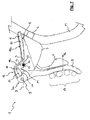
- Fig. 1 shows a partially sectional view along a vertical plane of a first embodiment of a control according to the invention, with the brake lever in a rest position, and in a first driving condition;
- Fig. 2 shows the control of fig. 1, with the brake lever pulled;
- Figs. 3 and 4 show the control of fig. 1, in different driving conditions;
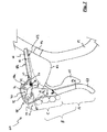
- Fig. 5 shows a partially sectional view along a vertical plane of a second embodiment of a control according to the invention, with the brake lever in a rest position;
- Fig. 6 shows the control of fig. 5, with the brake lever pulled;
- Fig. 7 shows a partially sectional view along a vertical plane of a third embodiment of a control according to the invention, with the brake lever in a rest position;
- Fig. 8 shows the control of fig. 7 with the brake lever pulled.
- A first embodiment of a brake control device for a curved handle bar bicycle is shown in figures 1 to 4.
- The control device, referenced generally with 1, is more particularly an integrated control device, i.e. for controlling not only the brake, but also a derailleur traction cable. However, only a
gearshift lever 2 is visible in the figures, while the inner mechanism for controlling the derailleur cable is not shown and is not described because it goes beyond the subject-matter of the invention, and could have any configuration known in the art, merely as an example that described in above mentioned patentEP 0 504 118 B1 . - The
control device 1 comprises asupport body 3, connectable to a grip portion of a curved handle bar M, for example through a clip 4, so as to protrude frontally from the handle bar M. - The
support body 3 has aseat 20 to host a sheathed cable or Bowdencable 5 used for controlling the brake in a per se known way. In particular, theseat 20 extends along theupper surface 18b of thesupport body 3 and hosts theouter sheath 6 of the Bowdencable 5, which is placed in abutment against ashoulder 7 of thesupport body 3. - A
brake lever 8 is pivoted to the upper end 3a of thesupport body 3 about a pivot 9. Thebrake lever 8 has abend 10 in the proximity of the pivot 9. - A
transmission member 11 is interposed between thebrake lever 8 and amember 15 holding thehead 16 of theinner cable 17 of the Bowdencable 5. Thecable head holder 15 is typically a pin having a transversal hole and free to rotate to allow the end length of theinner cable 17 of the Bowdencable 5, fixed in the transversal hole, to take up an essentially straight direction X between theshoulder 7 and thecable head holder 15 itself. - Advantageously, but not necessarily, the
entire seat 20 for theouter sheath 6 of theBowden cable 5 extends in thesupport body 3 along direction X. - The pivot 9 of the
brake lever 8 is above the direction X of the end length of theBowden cable 5. The pivot 9 of thebrake lever 8 moreover is arranged essentially at the upper end of thebrake lever 8. - The
transmission member 11 comprises twobranches support body 3 about apivot 12 at the end common to the twobranches first branch 13 of thetransmission member 11 is in contact with thebend 10 of thebrake lever 8, and the free end of thesecond branch 14 hosts thecable head holder 15. - The upper end of the
brake lever 8 and thetransmission member 11 are housed in aprotrusion 18 of thesupport body 3. - When the cyclist pulls the
brake lever 8 towards the handle bar M, as shown in figure 2, thebend 10 of thebrake lever 8 pushes thefirst branch 13 of thetransmission member 11 upwards, consequently rotating thetransmission member 11 and itssecond branch 14 aboutpivot 12, in clockwise direction with reference to figures 1 to 4. The free end of thesecond branch 14, where there is themember 15 for holding thehead 16 of theinner cable 17 of theBowden cable 5, while rotating causes the traction of thehead 16 of theinner cable 17, and so it actuates the braking. - Because of the comparably long length of the
second branch 14, advantageously its free end and so thehead 16 of theinner cable 17 of theBowden cable 5 make an essentially linear displacement along direction X. It is to be noted in fact that, in the condition wherein thebrake lever 8 is pulled, the end length of theinner cable 17 of theBowden cable 5 extends along a direction X' which does not differ essentially from direction X. In practice, during the braking movement the end length of theBowden cable 5 can take up a series of intermediate directions between the direction X and the direction X'. It is however noted that the end length of theBowden cable 5 is always maintained below the pivot 9 of thebrake lever 8. - Cable bending and twisting are in this way advantageously avoided and so the friction with the
sheath 6 of thebrake cable 5 is reduced, with consequent less wear of thecable 5 and increased efficiency of the braking action. - In figure 1 the position of the cyclist's fingers other than the thumb is schematically shown in the driving condition wherein the cyclist grips the handle bar M. The fingers rest on the
brake lever 8 at a first actuation area A, at the bottom end of thebrake lever 8. - In figures 3 and 4 the positions of the cyclist's fingers other than the thumb are schematically shown in the driving condition wherein the cyclist grips instead the
support body 3 of thecontrol device 1. - According to figure 3, the cyclist rests the hand palm on the
upper surface 18b of thesupport body 3. The fingers rest on thebrake lever 8 at a second actuation area B, intermediate along thebrake lever 8. - According to figure 4, the cyclist grips the
protrusion 18 of thesupport body 3, resting the hand palm on the proximal surface 18a of theprotrusion 18. The fingers rest on thebrake lever 8 at a third actuation area C, towards the upper end of thebrake lever 8. - It is to be noted that all the three actuation areas A, B and C extend on the same side of the
brake lever 8 with respect to the pivot 9, thanks to the particularly high arrangement of the pivot 9 of thebrake lever 8, above the direction X, X' of theBowden cable 5. All the cyclist's fingers other than the thumb are so able to apply an efficient power on thebrake lever 8. - Moreover, the point of application of the resistance, i.e. the
bend 10, is interposed between the fulcrum, i.e. pivot 9, and the point of application of the resultant force PA, PB and respectively PC of the power distribution, which is essentially the intermediate point of the actuation area A, B or respectively C. Thebrake lever 8 of the embodiment of figures 1 to 4 is thus a second class lever, which is always mechanically advantageous, both with reference to the actuation area A and with reference to the actuation area B, as well as with reference to the actuation area C. - Moreover, as the
bend 10 is made on thebrake lever 8 in close proximity of the pivot 9, the resisting arm of thebrake lever 8 is very short. The transmission means comprised of thetransmission member 11 allow in any case to obtain the necessary stroke of theinner cable 17 of theBowden cable 5, for any swinging angle of thelever 8, independently of the resisting arm. - Thanks to the very short resisting arm of the
brake lever 8, the force applied toBowden cable 5 is therefore large, even applying a relatively small force. - Summarizing, the
brake lever 8 of thecontrol device 1 of the embodiment according to figures 1 to 4 can be safely and efficiently actuated not only from the driving condition gripping on the handle bar, but also from the driving conditions resting on thesupport body 3 of thecontrol device 1, without the need of moving the hand downwards to move the fingers onto the useful side of the brake lever, i.e. below its pivot and/or to increase the power arm, as it is on the contrary necessary with the control devices of the prior art. - In figures 5 and 6 a second embodiment of a brake control device of a bicycle with a curved handle bar is shown, referenced as a whole with 31. Also in the case of this embodiment, it is more particularly an integrated control device, wherein as far as the derailleur gearshifting function is concerned, only a
gearshift lever 32 is shown. - The
control device 31 comprises asupport body 33, connectable to a grip portion of a curved handle bar M, for example through aclip 34, so as to project frontally from handle bar M. - The
support body 33 has a seat 50 to house aBowden cable 35 for controlling the brake. In particular, the seat 50 extends along theupper surface 58b of thesupport body 33, and houses theouter sheath 36 of theBowden cable 35, which is arranged in abutment against ashoulder 37 of thesupport body 33. - A
brake lever 38 is pivoted essentially at the upper end of thesupport body 33 about apivot 39. It is to be noted that aprotrusion 58 of thesupport body 33 extends in figures 5 and 6 upwards beyond thebrake lever 38, but this is not necessary and in particular thesupport body 33 could have the shape of thesupport body 3 shown in figures 1 to 4, thebrake lever 38 being in this case essentially pivoted at the upper end of the support body. - Transmission means 40 are arranged between the
brake lever 38 and a member 44a holding thehead 46 of theinner cable 47 of theBowden cable 35. The cable head holder 44a is typically a pin with a transversal hole and free to rotate to allow that the end length of theinner cable 47 of theBowden cable 35, fixed in the transversal hole, takes up an essentially straight direction X between theshoulder 37 and the cable head holder 44a itself. - Advantageously, but not necessarily, the entire seat 50 for the
outer sheath 36 of theBowden cable 35 extends in thesupport body 33 along direction X. - As in the case of the first embodiment described above, the
pivot 39 of thebrake lever 38 is arranged above with respect to the direction X of the end length of theBowden cable 35. Thepivot 39 is also arranged essentially at the upper end of thebrake lever 38. - The transmission means 40 comprises a first and a
second transmission members 41 and 42. Thefirst transmission member 41 comprises twobranches support body 33 about apivot 45 at the end common to the twobranches second branch 44 houses the cable head holder 44a. The second transmission member 42 is pivoted on one side to the free end of thefirst branch 43 of thefirst transmission member 41 about apivot 48, and on the other side it is pivoted to thebrake lever 38 about apivot 49. Thepivot 49 is arranged in an area of thebrake lever 38 essentially along the direction X of theBowden cable 35. - The upper end of the
brake lever 38 and the transmission means 40 are housed in theprotrusion 58 of thesupport body 33. - When the cyclist pulls the
brake lever 38 towards the handle bar M, as shown in figure 6, the free end of the second transmission member 42 is pushed upwards, and in turn it pushes the free end of thefirst branch 43 of thefirst transmission member 41 upwards, as a consequence rotating thefirst transmission member 41 and itssecond branch 44 aboutpivot 45, clockwise referring to figures 5 and 6. The free end of thesecond branch 44, where there is the member 44a holding thehead 46 of theinner cable 47 of theBowden cable 35, when rotating causes the pull of thehead 46 of theinner cable 47 of theBowden cable 35, and therefore it actuates the braking. - Due to the comparably long length of the
second branch 44, advantageously its free end and thus thehead 46 of theinner cable 47 of theBowden cable 35 make an essentially linear motion along the direction X, avoiding bending and twisting and thus reducing the friction with thesheath 36 of thebrake cable 35, with consequent less wear of thecable 35 and increased efficiency of the braking action. In the condition wherein thebrake lever 38 is pulled, the end length of theinner cable 47 of theBowden cable 35 extends along a direction X' which is essentially coincident with direction X. In practice, during the braking movement the end length of theBowden cable 35 can take up a series of intermediate directions between the direction X and the direction X', still always keeping itself below thepivot 49 of thebrake lever 38. - In figure 5 the three actuation areas A, B and C are shown, in the driving conditions wherein the cyclist grips the handle bar M, wherein the cyclist rests the hand palm on the
upper surface 58b of thesupport body 33, and wherein the cyclist grips theprotrusion 58 of thesupport body 33, resting the hand palm on the proximal surface 58a of theprotrusion 58. For reasons of clarity, the position of the fingers is only shown with reference to the actuation area C, which is the most critical area. The respective resultant forces PA, PB, PC of the power distribution are also shown. - It should be noted that all the three actuation areas A, B and C extend on the same side of the
brake lever 38 with respect to thepivot 39, thanks to the particularly high arrangement of thepivot 39 of thebrake lever 38, above the direction X, X' of theBowden cable 35. All the cyclist's fingers other than the thumb are thus able to apply an efficient power to thebrake lever 38. - The
brake lever 38 of the embodiment of figures 5 and 6 is a mechanically advantageous second class lever, with reference to actuation areas A and B. - With reference to actuation area C, the ring finger, the medium finger and the little finger also work in the mechanically advantageous conditions of a second class lever. Moreover, also the forefinger applies an efficient power because it is below
pivot 39, even if it works in a condition essentially of indifference or of mechanical disadvantage. The overall power PC applied to thebrake lever 38 is thus comparably large. Moreover, the arm of the resultant PC of the power distribution is in any case longer than the resisting arm. Also with reference to actuation area C, thebrake lever 38 is therefore a mechanically advantageous second class lever. - The transmission means 40 also allows to obtain the necessary stroke of the
inner cable 47 of theBowden cable 35, for any swinging angle of thelever 38, independently of the resisting arm. - Summarizing, the
brake lever 38 of thecontrol device 31 of the embodiment according to figures 5 and 6 can be safely and efficiently actuated not only from the driving condition gripping on the handle bar, but also from the driving conditions resting on thesupport body 33 of thecontrol device 31, without the need of moving the hand downwards to bring the fingers on the useful side of the brake lever, i.e. below the pivot and/or to increase the power arm, as it is necessary with the control devices of the prior art. - In figures 7 and 8 a third embodiment of a brake control device of a curved handle bar bicycle is shown, referenced as a whole with 61. Also in the case of this embodiment, it is more particularly an integrated control device, wherein as far as the derailleur gearshifting function is concerned, only a
gearshift lever 62 is shown. - The
control device 61 comprises asupport body 63, connectable to a grip portion of a curved handle bar M, for example through aclip 64, so as to frontally protrude from the handle bar M. - The
support body 63 has aseat 80 for housing aBowden cable 65 for controlling the brake. In particular, theseat 80 extends along the upper surface 88b of thesupport body 63, and it houses theouter sheath 66 of theBowden cable 65, which is arranged in abutment against ashoulder 67 of thesupport body 63. - A
brake lever 68 is pivoted to thesupport body 63 about a pivot 69. - Transmission means 70 is interposed between the
brake lever 68 and a member 71a holding thehead 76 of theinner cable 77 of theBowden cable 65. The cable head holder 71a is typically a pin having a transversal hole and free to rotate to allow the end length of theinner cable 77 of theBowden cable 65, fixed in the transversal hole, to take up an essentially straight direction X between theshoulder 67 and the cable head holder 71a itself. - Advantageously, but not necessarily, the
entire seat 80 for theouter sheath 66 of theBowden cable 65 extends in thesupport body 63 along the direction X. - The pivot 69 of the
brake lever 68 is arranged essentially on the direction X of the end length of theBowden cable 65. - The transmission means 70 comprises a first and a
second transmission members first transmission member 71 is pivoted at a first end on thesupport body 63 about apivot 74. At its second end, thefirst transmission member 71 houses the cable head holder 71a. Thesecond transmission member 72 is pivoted at a first end to the second end of thefirst transmission member 71, at the cable head holder 71a, and at the other end it is pivoted to thebrake lever 68 about a pivot 79 in an upper end area of thebrake lever 68. - The upper end of the
brake lever 68 and the transmission means 70 are housed in aprotrusion 88 of thesupport body 63. - When the cyclist pulls the
brake lever 68 towards the handle bar M, as shown in figure 8, thesecond transmission member 72 is pulled away from the handle bar M and in turn it pulls the free end of thefirst transmission member 71, rotating it about thepivot 74 in a clockwise direction with reference to figures 7 and 8. The free end of thefirst transmission member 71, where there is the cable head holder 71a, when rotating causes the traction of thehead 76 of theinner cable 77 of theBowden cable 65, and so it actuates the braking. - Because of the comparably long length of the
first transmission member 71, advantageously its free end and thus thehead 76 of theinner cable 77 of theBowden cable 65 make an essentially linear displacement along direction X, avoiding bending and twisting and thus reducing friction with thesheath 66 of thebrake cable 65, with consequent less wear of thecable 65 and increased efficiency of the braking action. In the condition when thebrake lever 68 is pulled, the end length of theinner cable 77 of theBowden cable 65 extends along a direction X' only slightly differing from direction X. In practice, during the braking movement the end length of theBowden cable 35 can take up a series of intermediate directions between direction X and direction X', still always remaining below the pivot 69 of thebrake lever 68. - In figure 7 three actuation areas A, B e C are shown in the driving conditions wherein the cyclist grips the handle bar M, wherein the cyclist rests the hand palm on the upper surface 88b of the
support body 63, and wherein the cyclist grips theprotrusion 88 of thesupport body 63, resting the hand palm on the proximal surface 88a of theprotrusion 88. For clarity, the position of the fingers is shown only with reference to the actuation area C, that is the most critical area. The respective resultant forces PA, PB, PC of the power distribution are also shown. - It is noted that the actuation areas A, B and essentially the entire actuation area C extend on the same side of the
brake lever 68 with respect to pivot 69, thanks to the upper arrangement of the pivot 69 of thebrake lever 68, above the direction X, X' of theBowden cable 65. All cyclist's fingers other than the thumb are thus able to apply an efficient power to thebrake lever 68 in the driving conditions wherein the cyclist grips the handle bar M and wherein the cyclist rests the hand palm on the upper surface 88b of thesupport body 63. In the driving condition wherein the cyclist grips theprotrusion 88 of thesupport body 63, at least the medium finger, the ring finger and the little finger are able to apply an efficient power to thebrake lever 68, even if the forefinger may also fall essentially at the pivot 69 of thebrake lever 68. - The
brake lever 68 of the embodiment of figures 7e 8 is a first class lever both with reference to the actuation area A and with reference to the actuation area B. - With reference to the actuation area C, the medium finger, the ring finger and the little finger work in conditions of mechanical advantage because the arm of their respective powers is greater than the resisting arm. Furthermore, also the forefinger applies an efficient power because it rests below the pivot 69, even if it works in essentially indifference or mechanical disadvantage conditions. The total power applied to the
brake lever 68 is therefore comparably large. Furthermore, the arm of the resultant force of the power distribution PC is in any case longer than the resisting arm. Also with reference to the actuation area C, thebrake lever 68 is therefore a mechanically advantageous lever. - The transmission means 70 also allow the necessary stroke of the
inner cable 77 of theBowden cable 65 to be obtained, for any swinging angle of thelever 68, independently of the resisting arm, that can therefore be made comparably short. - Summarizing, the
brake lever 68 of thecontrol device 61 of the embodiment according to figures 7 and 8 can be safely actuated not only from the driving condition gripping on the handle bar, but also from the driving conditions resting on thesupport body 63 of thecontrol device 61, without the need of displacing the hand downwards to bring the fingers on the useful side of the brake lever, namely below the pivot and/or to increase the power arm, as it is on the contrary necessary with the control devices of the prior art. - In the various embodiments described above, the actuation areas A, B e C may be anatomically shaped on the
brake lever - It will be understood that the invention may find an advantageous application also in the case of brake control devices not integral with the derailleur control, as well as to integral or not integral control devices for bicycles not with a curved handle bar, for example for bicycles with straight handle bar as it is typical of the mountain bikes, if it is desired to provide for the capability of actuating the brake not only from its end actuation area intended for the grip on the handle bar, but also from driving conditions wherein the cyclist grips the support body of the control device and therefore he/she does not reach said actuation area with the fingers.
Claims (17)
- Bicycle-brake control device (1, 31, 61), comprising a support body (3, 33, 63) to be fixed to a handle bar (M) and suitable to receive an end length of a traction cable (5, 35, 65) according to a direction (X, X'), and a brake lever (8, 38, 68) pivoted on the support body (3, 33, 63) for actuating the brake through the traction cable (5, 35, 65) when it is pulled towards the handle bar (M), the brake lever (8, 38, 68) having a first actuation area (A) at one end, characterized in that the pivot (9, 39, 69) of the brake lever (8, 38, 68) is arranged in a position that is not intermediate between the intersection of said direction (X, X') with the brake lever (8, 38, 68), and the first actuation area (A) of the brake lever (8, 38, 68).
- Control device (1, 31, 61) according to claim 1, characterized in that the direction (X, X') of the end length of the traction cable (5, 35, 65) is defined in the support body (3, 33, 63) by an abutting shoulder (7, 37, 67) for a sheath (6, 36, 66) of the brake cable (5, 35, 65), and by a member (15, 44a, 71a) holding the head (16, 46, 76) of the traction cable (5, 35, 65).
- Control device (1, 31, 61) according to claim 1 or 2, characterized by motion transmission means (11, 40, 70) interposed between the brake lever (8, 38, 68) and a member (15, 44a, 71a) holding the head (16, 46, 76) of the traction cable (5, 35, 65).
- Control device (1, 31, 61) according to claim 3, characterized in that the transmission means (11, 40, 70) are configured to pull the member (15, 44a, 71a) holding the head (16, 46, 76) of the traction cable (5, 35, 65) essentially along said direction (X, X').
- Control device (1, 31, 61) according to claim 3 or 4, characterized in that the transmission means (11, 40, 70) comprises a transmission member (11, 41, 71) pivoted (12, 45, 74) on the support body (3, 33, 63) and rotary moved by the brake lever (8, 38, 68), the member (15, 44a, 71a) holding the head (16, 46, 76) of the traction cable (5, 35, 65) being fixed at a free end of said member (11, 41, 71) pivoted (12, 45, 74) on the support body (3, 33, 63).
- Control device (1) according to claim 5, characterized in that the transmission member (11) pivoted on the support body (3) is cam coupled on a bend (10) of the brake lever (8).
- Control device (31, 61) according to claim 5, characterized in that the transmission means (40, 70) comprises a second transmission member (42, 72) pivoted (49, 79) at one end on the brake lever (38, 68) and at the other end pivoted (48, 71a) on the transmission member (41, 71) pivoted on the support body (33, 63).
- Control device (1, 31) according to any of the preceding claims, characterized in that the pivot (9, 39) of the brake lever (8, 38) is arranged at one end of the brake lever (8, 38).
- Control device (1, 31, 61) according to any of the preceding claims, characterized in that the brake lever (8, 38, 68) has at least two actuation areas (A, B, C) along its length.
- Control device (1, 31, 61) according to claim 9, characterized in that the actuation areas (A, B, C) are anatomically shaped.
- Control device (1, 31, 61) according to any of the preceding claims, characterized in that the support body (3, 33, 63) is intended to be fixed to a curved handle bar (M).
- Control device (1, 31) according to claim 11, characterized in that the pivot (9, 39) of the brake lever (8, 38) is arranged on the support body (3, 33) in a position that is above said direction (X, X').
- Control device (61) according to claim 11, characterized in that the pivot (69) of the brake lever (68) is arranged on the support body (63) in a position which is essentially along said direction (X, X').
- Control device (1, 31, 61) according to any of the claims 11-13, characterized in that the support body (3, 33, 63) has a frontal-upper protrusion (18, 58, 88).
- Control device (1, 31, 61) according to claim 14, characterized in that the frontal-upper protrusion (18, 58, 88) is grippable.
- Control device (1, 31, 61) according to claim 14 or 15 when directly or indirectly depending on claim 3, characterized in that the transmission means (11, 40, 70) are housed in the protrusion (18, 58, 88).
- Control device (1, 31, 61) according to any of the preceding claims, characterized by further comprising means (2, 32, 62) for controlling a bicycle derailleur.
Priority Applications (7)
| Application Number | Priority Date | Filing Date | Title |
|---|---|---|---|
| DE602006015158T DE602006015158D1 (en) | 2006-02-23 | 2006-02-23 | Bicycle brake control device |
| AT06003694T ATE472468T1 (en) | 2006-02-23 | 2006-02-23 | BICYCLE BRAKE CONTROL DEVICE |
| EP06003694A EP1826111B1 (en) | 2006-02-23 | 2006-02-23 | Bicycle brake control device |
| TW096105856A TWI376331B (en) | 2006-02-23 | 2007-02-15 | Bicycle brake control device |
| US11/708,919 US8833199B2 (en) | 2006-02-23 | 2007-02-21 | Bicycle brake control device |
| JP2007042369A JP5224697B2 (en) | 2006-02-23 | 2007-02-22 | Bicycle brake control device |
| CN200710005823.3A CN101024414B (en) | 2006-02-23 | 2007-02-25 | Bicycle brake control device |
Applications Claiming Priority (1)
| Application Number | Priority Date | Filing Date | Title |
|---|---|---|---|
| EP06003694A EP1826111B1 (en) | 2006-02-23 | 2006-02-23 | Bicycle brake control device |
Publications (2)
| Publication Number | Publication Date |
|---|---|
| EP1826111A1 true EP1826111A1 (en) | 2007-08-29 |
| EP1826111B1 EP1826111B1 (en) | 2010-06-30 |
Family
ID=36675939
Family Applications (1)
| Application Number | Title | Priority Date | Filing Date |
|---|---|---|---|
| EP06003694A Expired - Lifetime EP1826111B1 (en) | 2006-02-23 | 2006-02-23 | Bicycle brake control device |
Country Status (7)
| Country | Link |
|---|---|
| US (1) | US8833199B2 (en) |
| EP (1) | EP1826111B1 (en) |
| JP (1) | JP5224697B2 (en) |
| CN (1) | CN101024414B (en) |
| AT (1) | ATE472468T1 (en) |
| DE (1) | DE602006015158D1 (en) |
| TW (1) | TWI376331B (en) |
Cited By (4)
| Publication number | Priority date | Publication date | Assignee | Title |
|---|---|---|---|---|
| EP2062809A3 (en) * | 2007-11-23 | 2010-12-08 | CAMPAGNOLO S.r.l. | Control device for a bicycle with curved handlebars |
| US9267536B2 (en) | 2005-06-27 | 2016-02-23 | Campagnolo S.R.L. | Control device for a bicycle derailleur |
| US10118664B2 (en) | 2007-03-01 | 2018-11-06 | Campagnolo S.R.L. | Control device for a bicycle and bicycle comprising such a device |
| US10202164B2 (en) | 2004-02-06 | 2019-02-12 | Campagnolo S.R.L. | Actuation device for a control cable for a bicycle gearshift |
Families Citing this family (14)
| Publication number | Priority date | Publication date | Assignee | Title |
|---|---|---|---|---|
| ITTO20011079A1 (en) | 2001-11-16 | 2003-05-16 | Campagnolo Srl | ,, GEARBOX CONTROL DEVICE FOR A BICYCLE WITH A HANDLEBAR WITH STRAIGHT ENDS ,, |
| JP5027999B2 (en) * | 2005-07-08 | 2012-09-19 | キヤノン株式会社 | Recording apparatus and control method thereof |
| JP2009523652A (en) | 2006-01-23 | 2009-06-25 | カンパニョーロ・ソシエタ・ア・レスポンサビリタ・リミタータ | Control device for bicycle derailleur |
| EP1826111B1 (en) | 2006-02-23 | 2010-06-30 | CAMPAGNOLO S.r.l. | Bicycle brake control device |
| ITMI20070239A1 (en) | 2007-02-09 | 2008-08-10 | Campagnolo Srl | CONTROL DEVICE FOR A BICYCLE DERAILLEUR |
| JP2011159111A (en) * | 2010-02-01 | 2011-08-18 | Shimano Inc | Bicycle brake and shift operating device |
| EP3018048B1 (en) | 2014-11-06 | 2019-03-06 | Campagnolo S.R.L. | Manual control device for a bicycle, in particular of hydraulic brake and gearshift |
| CN107416103B (en) * | 2016-05-23 | 2019-07-26 | 株式会社岛野 | Bicycle operating device |
| TWI582004B (en) * | 2016-09-14 | 2017-05-11 | Dong Her Wu | Bicycle brakes aids |
| US11618529B2 (en) | 2020-06-03 | 2023-04-04 | Dextera Brakes, Llc | Grip assembly for vehicle |
| US20210380079A1 (en) * | 2020-06-03 | 2021-12-09 | Dextera Brakes, Llc | Lever System |
| WO2022086861A1 (en) * | 2020-10-19 | 2022-04-28 | Tonal Systems, Ins. | Exercise machine arm with single-handed adjustment |
| DE102021128661A1 (en) | 2021-11-04 | 2023-05-04 | Shimano Inc. | ACTUATOR FOR A MUSCLE-POWERED VEHICLE |
| CN114802577B (en) * | 2022-06-08 | 2024-02-02 | 珠海蓝图运动科技股份有限公司 | Bicycle brake control device and bicycle |
Citations (7)
| Publication number | Priority date | Publication date | Assignee | Title |
|---|---|---|---|---|
| CH248133A (en) * | 1946-08-06 | 1947-04-15 | Leclercq Lambert Antoinette | Control device, by cable circulating in a flexible sheath, in particular applicable to the control of a cycle or motorcycle brake. |
| GB615173A (en) * | 1946-02-23 | 1949-01-03 | Charles Somville | Improvements in control-lever mechanism |
| FR960276A (en) * | 1950-04-15 | |||
| JPH03292280A (en) * | 1989-12-26 | 1991-12-24 | Shimano Inc | Brake operating device for bicycle |
| EP0504118A1 (en) | 1991-03-11 | 1992-09-16 | Campagnolo S.R.L. | A brake and gear change control unit for a bicycle |
| EP0635422A2 (en) * | 1993-07-23 | 1995-01-25 | Yoshigai Kikai Kinzoku Co., Ltd. | Operating lever devices |
| EP1449756A1 (en) * | 2003-02-20 | 2004-08-25 | Shimano Inc. | Bicycle control device |
Family Cites Families (132)
| Publication number | Priority date | Publication date | Assignee | Title |
|---|---|---|---|---|
| US735113A (en) * | 1901-12-17 | 1903-08-04 | John Kelland | Brake for cycles or vehicles. |
| US1706542A (en) * | 1925-09-03 | 1929-03-26 | Rudge Whitworth Ltd | Cycle or like brake |
| US1760542A (en) * | 1928-01-10 | 1930-05-27 | Gen Electric | Electroresponsive device |
| US2384728A (en) * | 1944-04-27 | 1945-09-11 | James H Crumble | Vehicle |
| US2586604A (en) | 1949-12-19 | 1952-02-19 | Westward Washing Machine Compa | Flexible coupling |
| US2770980A (en) * | 1952-11-07 | 1956-11-20 | J A Phillips And Company Ltd | Variable speed gear control lever mechanism for bicycles and like vehicles |
| US2854857A (en) * | 1954-05-03 | 1958-10-07 | Bendix Aviat Corp | Flexible remote actuating means for a two-speed coaster brake |
| US3279779A (en) | 1964-07-20 | 1966-10-18 | Lord Corp | Combined disc and elastomeric spring |
| JPS5028530Y2 (en) * | 1972-06-14 | 1975-08-22 | ||
| US3760648A (en) * | 1972-12-18 | 1973-09-25 | W Hoffman | Auxiliary bicycle brake handle |
| US3915029A (en) | 1974-09-09 | 1975-10-28 | Shimano Industrial Co | Operating lever for gear-shifting means of a bicycle |
| US3972247A (en) | 1974-09-23 | 1976-08-03 | Armstrong Allen E | Bicycle shift mechanism |
| JPS536603Y2 (en) | 1974-11-01 | 1978-02-20 | ||
| US4002350A (en) | 1975-03-17 | 1977-01-11 | Timbs Norman E | Single lever control for variable speed bicycles and the like |
| US4075871A (en) | 1976-02-27 | 1978-02-28 | General Motors Corporation | Double Cardan joint with elastomeric centering means |
| US4100820A (en) | 1976-09-13 | 1978-07-18 | Joel Evett | Shift lever and integral handbrake apparatus |
| GB2012893B (en) | 1978-01-12 | 1982-03-10 | Ti Raleigh Ind Ltd | Control means for elongate members |
| JPS583987B2 (en) | 1978-06-30 | 1983-01-24 | 松下電工株式会社 | Mineral coating composition |
| JPS5742158Y2 (en) | 1978-10-06 | 1982-09-16 | ||
| JPS6144950Y2 (en) | 1980-09-10 | 1986-12-17 | ||
| JPS6031985Y2 (en) | 1980-11-19 | 1985-09-25 | 株式会社シマノ | Gear shift operation device |
| JPS583987U (en) * | 1981-06-29 | 1983-01-11 | 小松ゼノア株式会社 | blower device |
| JPS5830884A (en) | 1981-08-14 | 1983-02-23 | ブリヂストンサイクル株式会社 | Brake lever for bicycle |
| US4740001A (en) | 1981-09-14 | 1988-04-26 | Torleumke Keith R | Sprag wheel |
| DE3136922A1 (en) | 1981-09-17 | 1983-03-31 | Hans Christian Ing.(grad.) 5042 Erftstadt Smolik | Index mechanism |
| US4605240A (en) | 1983-08-18 | 1986-08-12 | Telewe', Inc. | Electronically controlled bicycle transmission |
| JPS60107475U (en) | 1983-12-26 | 1985-07-22 | リンナイ株式会社 | Float type constant flow governor |
| US4751850A (en) | 1984-04-03 | 1988-06-21 | Shimano Industrial Company, Limited | Speed change operating device for a bicycle |
| JPS6128914A (en) | 1984-07-19 | 1986-02-08 | Canon Inc | Automatic tracking device in camera |
| USD298309S (en) | 1984-12-27 | 1988-11-01 | Huret Et Ses Fils | Brake and derailleur actuating unit |
| US5020387A (en) | 1985-03-07 | 1991-06-04 | Shimano Industrial Company, Ltd. | Lever shifting device for a bicycle |
| JPH0657548B2 (en) | 1985-04-18 | 1994-08-03 | ヤマハ発動機株式会社 | Vehicle braking lever position adjusting device |
| JPH0616170B2 (en) | 1986-07-25 | 1994-03-02 | ホ−ヤ株式会社 | Photo mask blank and photo mask |
| FR2607462B1 (en) | 1986-11-27 | 1990-03-23 | Huret Sachs Sa | INDEXING CONTROL DEVICE FOR CYCLE DERAILLEUR |
| USRE34007E (en) | 1986-11-27 | 1992-07-28 | Sachs Industries S.A. (Huret et Millard reunis) | Indexation control device for a cycle derailleur |
| DE3706545A1 (en) | 1987-02-28 | 1988-09-08 | Bayerische Motoren Werke Ag | Hand lever device for motorcycle handlebars or the like |
| KR900008424B1 (en) | 1987-06-05 | 1990-11-20 | 닛신 고오교오 가부시끼가이샤 | Vehicle lever device |
| IT1219256B (en) | 1988-05-02 | 1990-05-03 | Campagnolo Spa | ADJUSTABLE SUPPORT FOR CONTROL LEVERS TO BE MOUNTED ON A HANDLEBAR OF A MOTORCYCLE OR SIMILAR CYCLE |
| CN2036151U (en) * | 1988-05-26 | 1989-04-19 | 陈北列 | Line brake and brake system for bicycle, motor bicycle |
| US5222412A (en) | 1988-07-29 | 1993-06-29 | Shimano Industrial Co., Ltd. | Change speed lever apparatus for use in bicycle |
| US5012692A (en) | 1988-09-24 | 1991-05-07 | Shimano Industrial Company Limited | Change-speed lever apparatus for use in bicycle |
| US5400675A (en) | 1988-11-29 | 1995-03-28 | Shimano, Inc. | Bicycle control device |
| US5241878A (en) | 1988-11-29 | 1993-09-07 | Shimano, Inc. | Bicycle control device |
| JP2732116B2 (en) | 1988-11-29 | 1998-03-25 | 株式会社シマノ | Bicycle operation device |
| US4966046A (en) | 1989-06-05 | 1990-10-30 | Maeda Industries, Ltd. | Bicycle speed change lever assembly |
| JPH0313297U (en) | 1989-06-26 | 1991-02-12 | ||
| JP3007641B2 (en) * | 1989-07-06 | 2000-02-07 | 株式会社シマノ | Operating device for bicycle derailleur |
| JPH0338298U (en) | 1989-08-28 | 1991-04-12 | ||
| US5287765A (en) * | 1990-01-04 | 1994-02-22 | Brian Scura | Hand actuated cable displacement system |
| JP2523752Y2 (en) | 1990-03-26 | 1997-01-29 | マエダ工業株式会社 | Speed change lever device for bicycle |
| WO1991013797A1 (en) | 1990-03-09 | 1991-09-19 | Maeda Industries, Ltd. | Speed change control lever device for bicycle |
| JPH04143185A (en) | 1990-10-03 | 1992-05-18 | Maeda Kogyo Kk | Brake lever device for bicycle |
| JP3065656B2 (en) | 1990-11-14 | 2000-07-17 | 株式会社シマノ | Speed change device for bicycle |
| JPH04331689A (en) | 1991-01-10 | 1992-11-19 | Maeda Kogyo Kk | Brake lever device for bicycle |
| NL9100703A (en) | 1991-04-23 | 1992-11-16 | Maas Van Beek | USE BIKE HANDLE AND PARTS THEREFOR. |
| US5159851A (en) | 1991-09-18 | 1992-11-03 | Paul Rahmes | Bicycle grip |
| JP3283289B2 (en) | 1992-04-16 | 2002-05-20 | 株式会社シマノ | Bicycle brake operating device |
| JPH0616170A (en) | 1992-07-02 | 1994-01-25 | Maeda Kogyo Kk | Brake lever device for bicycle |
| JP2561412B2 (en) * | 1992-10-19 | 1996-12-11 | 吉貝機械金属株式会社 | Bicycle braking operation device |
| DE69204679T2 (en) | 1992-12-01 | 1996-03-07 | Frisco Findus Ag | Gripping device. |
| JP2601207Y2 (en) | 1992-12-28 | 1999-11-15 | 株式会社シマノ | Speed change device for bicycle |
| TW211548B (en) | 1993-03-09 | 1993-08-21 | Shimano Kk | Speed changing device of a bicycle |
| IT1261550B (en) | 1993-04-20 | 1996-05-23 | Antonio Romano | CONTROL DEVICE FOR THE CHANGE OF A BICYCLE. |
| IT1266817B1 (en) | 1994-02-24 | 1997-01-21 | Campagnolo Srl | SPEED CHANGE DEVICE FOR BICYCLES. |
| US5448927A (en) * | 1994-05-03 | 1995-09-12 | Avid Enterprises, Inc. | Adjustable leverage brake lever |
| US5787757A (en) | 1994-08-02 | 1998-08-04 | Sugino Cycle Industries, Ltd. | Bicycle speed change operation device |
| DE4442953C1 (en) | 1994-12-02 | 1996-02-08 | Fichtel & Sachs Ag | Drum switch for cycle gears |
| ATE252482T1 (en) | 1995-02-15 | 2003-11-15 | Shimano Kk | METHOD FOR DETERMINING THE GEAR RATIO AND CORRESPONDING DEVICE FOR SHIFTING A BICYCLE CHAIN GEARS |
| JP3449577B2 (en) | 1995-05-26 | 2003-09-22 | 株式会社シマノ | Bicycle brake and shifting device |
| JPH08328679A (en) | 1995-06-05 | 1996-12-13 | Yoshigai Kikai Kinzoku Kk | Operating lever device |
| US5676020A (en) | 1995-06-30 | 1997-10-14 | Sram Corporation | Hand-rotatable bicycle gear shift actuator with overshift return |
| IT1276466B1 (en) | 1995-07-04 | 1997-10-31 | Campagnolo Srl | BRAKE LEVER SUPPORT DEVICE FOR COMPETITION BICYCLES |
| IT1276465B1 (en) | 1995-07-04 | 1997-10-31 | Campagnolo Srl | COMPETITION BICYCLE HANDLEBAR, WITH DISPLAY DEVICE CARRIED BY THE BRAKE CONTROL UNIT |
| AT403466B (en) * | 1995-07-17 | 1998-02-25 | Wagner Rudolf | OPERATING DEVICE FOR CABLES, ESPECIALLY BICYCLE OR MOTORCYCLE BRAKES |
| IT1285834B1 (en) | 1995-10-19 | 1998-06-24 | Campagnolo Srl | CONTROL DEVICE OF A BICYCLE DERAILLEUR, INCLUDING AN ANTAGONIST SPRING OF THE DERAILLEUR SPRING. |
| IT1281313B1 (en) | 1995-10-19 | 1998-02-17 | Campagnolo Srl | GEAR CONTROL DEVICE FOR A "MOUNTAIN-BIKE" OR SIMILAR TYPE. |
| US5730030A (en) | 1996-01-19 | 1998-03-24 | Shimano, Inc. | Shifting apparatus for bicycles having a brake operating unit disposed between first and second shifting levers |
| TW378183B (en) | 1996-02-14 | 2000-01-01 | Shimano Kk | Bicycle shift levers which surround a handlebar |
| US5921140A (en) | 1996-04-04 | 1999-07-13 | Fichtel & Sachs Ag | Index shifter for a bicycle transmission and a method of making an index shifter for a bicycle transmission |
| JP3005204B2 (en) | 1997-03-31 | 2000-01-31 | 株式会社シマノ | Bicycle motor control device |
| JP3474080B2 (en) | 1997-05-16 | 2003-12-08 | 株式会社シマノ | Bicycle switch |
| US5896779A (en) * | 1997-08-01 | 1999-04-27 | Sunrise Medical Hhg Inc. | Dual mode brake actuator for walker |
| DE19809113A1 (en) | 1998-03-04 | 1999-09-09 | Sram De Gmbh | Bicycle gear switch |
| FR2777528B1 (en) | 1998-04-17 | 2000-07-13 | Mavic Sa | SUPPORT HANDLE FOR A BRAKE LEVER PROVIDED FOR A RACING BICYCLE, AND ASSEMBLY FORMED BY THE SUPPORT HANDLE AND THE BRAKE LEVER |
| US6370961B1 (en) * | 1999-01-29 | 2002-04-16 | Constantin M. Trantzas | Nipped roller impression sensor system |
| US6295888B1 (en) | 1999-02-16 | 2001-10-02 | Shimano Inc. | Gear indicator for a bicycle |
| DE19915336A1 (en) | 1999-04-03 | 2000-10-05 | Sram De Gmbh | Gear shift for bicycles has continuous changing of gears using shift lever and gear lever, uncoupled by locking element |
| DE29910941U1 (en) * | 1999-06-22 | 1999-08-05 | Muchachos International Co., Ltd., Taichung | Bicycle brake lever |
| JP4249868B2 (en) | 1999-12-16 | 2009-04-08 | 日信工業株式会社 | Bar handle vehicle operating lever grip allowance adjustment mechanism |
| US6453764B1 (en) | 2000-03-03 | 2002-09-24 | Shimano, Inc. | Switch style bicycle shift control device |
| US6450060B1 (en) | 2000-03-17 | 2002-09-17 | Shimano, Inc. | Bicycle shift device having a linearly sliding shift lever operated by a pivoting cover |
| TW448901U (en) | 2000-05-19 | 2001-08-01 | Nat Science Council | Velocity control device |
| US20020078789A1 (en) | 2000-12-21 | 2002-06-27 | Chen Zen Ming | Brake lever having detachable hand grip |
| US6457377B1 (en) * | 2001-01-09 | 2002-10-01 | Apex Medical Corp. | Renovated brake structure for an auxiliary moving device |
| ITTO20010011A1 (en) | 2001-01-11 | 2002-07-11 | Campagnolo Srl | INTEGRATED GEARBOX AND BRAKE CONTROL GROUP FOR A BICYCLE. |
| ITTO20010010A1 (en) | 2001-01-11 | 2002-07-11 | Campagnolo Srl | INTEGRATED GEARBOX AND BRAKE CONTROL GROUP FOR A BICYCLE. |
| TW519089U (en) | 2001-03-15 | 2003-01-21 | Falcon Cycle Parts Co Ltd | Linear displacing type derailleur controller with two levers |
| TW558538B (en) | 2001-03-30 | 2003-10-21 | Shimano Kk | Bicycle control device |
| US20020139218A1 (en) | 2001-03-30 | 2002-10-03 | Akira Tsumiyama | Bicycle control device |
| ITTO20010555A1 (en) | 2001-06-08 | 2002-12-08 | Campagnolo Srl | ELECTRIC CONTROL DEVICE FOR A MOTORIZED FRONT DERAILLEUR FOR BICYCLES. |
| ITTO20011079A1 (en) | 2001-11-16 | 2003-05-16 | Campagnolo Srl | ,, GEARBOX CONTROL DEVICE FOR A BICYCLE WITH A HANDLEBAR WITH STRAIGHT ENDS ,, |
| JP3612304B2 (en) | 2002-03-07 | 2005-01-19 | 株式会社シマノ | Bicycle brake operating device |
| WO2003093094A2 (en) | 2002-05-03 | 2003-11-13 | Barnett Robert L | Control lever mount |
| CN2581313Y (en) * | 2002-10-14 | 2003-10-22 | 英隆机械(昆山)有限公司 | Braking structure for bicycle handlebar |
| US7152497B2 (en) | 2003-01-27 | 2006-12-26 | Shimano, Inc. | Method and apparatus for shifting a bicycle transmission by multiple steps |
| EP1473220A1 (en) | 2003-04-30 | 2004-11-03 | Campagnolo Srl | Control device for a bicycle derailleur |
| US7104154B2 (en) | 2003-05-29 | 2006-09-12 | Shimano Inc. | Bicycle shift control device |
| US7194928B2 (en) | 2003-05-30 | 2007-03-27 | Shimano Inc. | Bicycle shift operating device |
| US7062989B2 (en) | 2003-07-30 | 2006-06-20 | Shimano Inc. | Bicycle control device |
| FR2861686B1 (en) | 2003-11-04 | 2006-02-10 | Mavic Sa | SPEED CHANGE CONTROL ASSEMBLY COMBINED WITH A BRAKE CONTROL FOR A BIKE |
| US7228756B2 (en) | 2003-11-25 | 2007-06-12 | Shimano Inc. | Bicycle control device |
| DE602004008211T2 (en) | 2004-02-06 | 2007-12-20 | Campagnolo S.R.L. | Operating device for control cable of a bicycle transmission |
| US7779724B2 (en) | 2004-04-19 | 2010-08-24 | Shimano Inc. | Electrical bicycle shift control device |
| US7174805B2 (en) | 2004-04-30 | 2007-02-13 | Tektro Technology Corporation | Cross racing bike front brake lever |
| US20060070480A1 (en) | 2004-09-30 | 2006-04-06 | Shimano Inc. | Bicycle brake control device with electrical operating member |
| US7779718B2 (en) | 2005-03-03 | 2010-08-24 | Sram, Llc | Bicycle shifter |
| WO2006124417A2 (en) * | 2005-05-11 | 2006-11-23 | J. G. Starew Innovative Solutions, L.L.C. | Multi-passage guide system |
| US7802489B2 (en) | 2005-06-01 | 2010-09-28 | Shimano Inc. | Bicycle control device |
| ATE520583T1 (en) | 2005-06-27 | 2011-09-15 | Campagnolo Srl | CONTROL DEVICE FOR A BICYCLE CHAIN GEARS |
| EP1749738B1 (en) | 2005-08-04 | 2010-11-03 | Campagnolo S.r.l. | Actuation method and device for a control cable for a bicycle gearshift |
| JP4266986B2 (en) | 2005-08-24 | 2009-05-27 | 株式会社シマノ | Bicycle display device and bicycle control device |
| JP2009523652A (en) | 2006-01-23 | 2009-06-25 | カンパニョーロ・ソシエタ・ア・レスポンサビリタ・リミタータ | Control device for bicycle derailleur |
| US7703350B2 (en) | 2006-02-01 | 2010-04-27 | Shimano Inc. | Bicycle control device |
| US7503420B2 (en) | 2006-02-01 | 2009-03-17 | Shimano Inc. | Bicycle control device |
| US20070193388A1 (en) | 2006-02-03 | 2007-08-23 | Shimano Inc. | Bicycle shift control device |
| EP1826111B1 (en) | 2006-02-23 | 2010-06-30 | CAMPAGNOLO S.r.l. | Bicycle brake control device |
| DE202006006796U1 (en) | 2006-04-27 | 2006-08-03 | Wunderlich, Erich | Grip lever for operating motorcycle brake or clutch has protruding radial elements arranged on one end of axle that protrude beyond inclination adjuster |
| ITMI20062081A1 (en) | 2006-10-30 | 2008-04-30 | Campagnolo Srl | CONTROL DEVICE FOR BICYCLE AND RELATED PARTS KIT |
| ITMI20070239A1 (en) | 2007-02-09 | 2008-08-10 | Campagnolo Srl | CONTROL DEVICE FOR A BICYCLE DERAILLEUR |
| ITMI20070401A1 (en) | 2007-03-01 | 2008-09-02 | Campagnolo Srl | CONTROL DEVICE FOR BICYCLE AND BICYCLE INCLUDING THIS DEVICE |
| ITMI20070400A1 (en) | 2007-03-01 | 2008-09-02 | Campagnolo Srl | COMMAND DEVICE FOR BICYCLE AND BICYCLE INCLUDING SUCH DIPSOSITIVE |
| ITMI20072230A1 (en) | 2007-11-23 | 2009-05-24 | Campagnolo Srl | CONTROL DEVICE FOR BICYCLE WITH RECURCED HANDLEBAR |
-
2006
- 2006-02-23 EP EP06003694A patent/EP1826111B1/en not_active Expired - Lifetime
- 2006-02-23 DE DE602006015158T patent/DE602006015158D1/en not_active Expired - Lifetime
- 2006-02-23 AT AT06003694T patent/ATE472468T1/en not_active IP Right Cessation
-
2007
- 2007-02-15 TW TW096105856A patent/TWI376331B/en not_active IP Right Cessation
- 2007-02-21 US US11/708,919 patent/US8833199B2/en active Active
- 2007-02-22 JP JP2007042369A patent/JP5224697B2/en not_active Expired - Fee Related
- 2007-02-25 CN CN200710005823.3A patent/CN101024414B/en not_active Expired - Fee Related
Patent Citations (7)
| Publication number | Priority date | Publication date | Assignee | Title |
|---|---|---|---|---|
| FR960276A (en) * | 1950-04-15 | |||
| GB615173A (en) * | 1946-02-23 | 1949-01-03 | Charles Somville | Improvements in control-lever mechanism |
| CH248133A (en) * | 1946-08-06 | 1947-04-15 | Leclercq Lambert Antoinette | Control device, by cable circulating in a flexible sheath, in particular applicable to the control of a cycle or motorcycle brake. |
| JPH03292280A (en) * | 1989-12-26 | 1991-12-24 | Shimano Inc | Brake operating device for bicycle |
| EP0504118A1 (en) | 1991-03-11 | 1992-09-16 | Campagnolo S.R.L. | A brake and gear change control unit for a bicycle |
| EP0635422A2 (en) * | 1993-07-23 | 1995-01-25 | Yoshigai Kikai Kinzoku Co., Ltd. | Operating lever devices |
| EP1449756A1 (en) * | 2003-02-20 | 2004-08-25 | Shimano Inc. | Bicycle control device |
Non-Patent Citations (1)
| Title |
|---|
| PATENT ABSTRACTS OF JAPAN vol. 016, no. 129 (M - 1228) 2 April 1992 (1992-04-02) * |
Cited By (7)
| Publication number | Priority date | Publication date | Assignee | Title |
|---|---|---|---|---|
| US10202164B2 (en) | 2004-02-06 | 2019-02-12 | Campagnolo S.R.L. | Actuation device for a control cable for a bicycle gearshift |
| US9267536B2 (en) | 2005-06-27 | 2016-02-23 | Campagnolo S.R.L. | Control device for a bicycle derailleur |
| US9802671B2 (en) | 2005-06-27 | 2017-10-31 | Campagnolo S.R.L. | Control device for a bicycle derailleur |
| US10118664B2 (en) | 2007-03-01 | 2018-11-06 | Campagnolo S.R.L. | Control device for a bicycle and bicycle comprising such a device |
| US10308309B2 (en) | 2007-03-01 | 2019-06-04 | Campagnolo S.R.L. | Control device for a bicycle and bicycle comprising such a device |
| US10589817B2 (en) | 2007-03-01 | 2020-03-17 | Campagnolo S.R.L. | Control device for a bicycle and bicycle comprising such a device |
| EP2062809A3 (en) * | 2007-11-23 | 2010-12-08 | CAMPAGNOLO S.r.l. | Control device for a bicycle with curved handlebars |
Also Published As
| Publication number | Publication date |
|---|---|
| DE602006015158D1 (en) | 2010-08-12 |
| TW200738512A (en) | 2007-10-16 |
| US8833199B2 (en) | 2014-09-16 |
| JP2007223594A (en) | 2007-09-06 |
| US20070204716A1 (en) | 2007-09-06 |
| ATE472468T1 (en) | 2010-07-15 |
| JP5224697B2 (en) | 2013-07-03 |
| EP1826111B1 (en) | 2010-06-30 |
| CN101024414A (en) | 2007-08-29 |
| CN101024414B (en) | 2010-12-15 |
| TWI376331B (en) | 2012-11-11 |
Similar Documents
| Publication | Publication Date | Title |
|---|---|---|
| US8833199B2 (en) | Bicycle brake control device | |
| TWI281898B (en) | Gear-change control device for a bicycle | |
| US5921138A (en) | Bicycle shift device having a linearly sliding shift lever | |
| EP1976747B1 (en) | Control device for a bicycle derailleur | |
| JP6695126B2 (en) | Manual controls for bicycles, especially hydraulic brakes and gearshifts | |
| EP1918188A1 (en) | Control device for a bicycle and relative kit of parts | |
| US5617761A (en) | Shifting apparatus for a bicycle | |
| EP1134158A2 (en) | Bicycle shift device | |
| US20080168856A1 (en) | Bicycle brake and shift operating device | |
| EP1736404A1 (en) | Integrated control device for bicycle derailleur and brake | |
| EP0281567B1 (en) | Driving means of a bicycle brake, in particular a racing bicycle | |
| US20100313696A1 (en) | Control device with thumb trigger | |
| JP2013043642A (en) | Operation device of bar end type gear shift part of bicycle | |
| EP1577209A2 (en) | Bicycle trigger shifter | |
| US20070137387A1 (en) | Control device for a bicycle derailleur | |
| CZ128998A3 (en) | Bicycle shift control device having separately located control units | |
| EP1790564A1 (en) | Control device for a bicycle derailleur | |
| US20230365217A1 (en) | Manual control device for a bicycle | |
| EP1698551A2 (en) | Bicycle control apparatus | |
| EP2460716A1 (en) | Control lever and actuation device of a bicycle gearshift of the bar-end type |
Legal Events
| Date | Code | Title | Description |
|---|---|---|---|
| PUAI | Public reference made under article 153(3) epc to a published international application that has entered the european phase |
Free format text: ORIGINAL CODE: 0009012 |
|
| AK | Designated contracting states |
Kind code of ref document: A1 Designated state(s): AT BE BG CH CY CZ DE DK EE ES FI FR GB GR HU IE IS IT LI LT LU LV MC NL PL PT RO SE SI SK TR |
|
| AX | Request for extension of the european patent |
Extension state: AL BA HR MK YU |
|
| 17P | Request for examination filed |
Effective date: 20080208 |
|
| AKX | Designation fees paid |
Designated state(s): AT BE BG CH CY CZ DE DK EE ES FI FR GB GR HU IE IS IT LI LT LU LV MC NL PL PT RO SE SI SK TR |
|
| 17Q | First examination report despatched |
Effective date: 20080729 |
|
| GRAP | Despatch of communication of intention to grant a patent |
Free format text: ORIGINAL CODE: EPIDOSNIGR1 |
|
| GRAS | Grant fee paid |
Free format text: ORIGINAL CODE: EPIDOSNIGR3 |
|
| GRAA | (expected) grant |
Free format text: ORIGINAL CODE: 0009210 |
|
| AK | Designated contracting states |
Kind code of ref document: B1 Designated state(s): AT BE BG CH CY CZ DE DK EE ES FI FR GB GR HU IE IS IT LI LT LU LV MC NL PL PT RO SE SI SK TR |
|
| REG | Reference to a national code |
Ref country code: GB Ref legal event code: FG4D Ref country code: CH Ref legal event code: EP |
|
| REG | Reference to a national code |
Ref country code: IE Ref legal event code: FG4D |
|
| REF | Corresponds to: |
Ref document number: 602006015158 Country of ref document: DE Date of ref document: 20100812 Kind code of ref document: P |
|
| REG | Reference to a national code |
Ref country code: DE Ref legal event code: R096 Ref document number: 602006015158 Country of ref document: DE Effective date: 20100812 |
|
| REG | Reference to a national code |
Ref country code: NL Ref legal event code: VDEP Effective date: 20100630 |
|
| PG25 | Lapsed in a contracting state [announced via postgrant information from national office to epo] |
Ref country code: SE Free format text: LAPSE BECAUSE OF FAILURE TO SUBMIT A TRANSLATION OF THE DESCRIPTION OR TO PAY THE FEE WITHIN THE PRESCRIBED TIME-LIMIT Effective date: 20100630 Ref country code: LT Free format text: LAPSE BECAUSE OF FAILURE TO SUBMIT A TRANSLATION OF THE DESCRIPTION OR TO PAY THE FEE WITHIN THE PRESCRIBED TIME-LIMIT Effective date: 20100630 |
|
| LTIE | Lt: invalidation of european patent or patent extension |
Effective date: 20100630 |
|
| PG25 | Lapsed in a contracting state [announced via postgrant information from national office to epo] |
Ref country code: LV Free format text: LAPSE BECAUSE OF FAILURE TO SUBMIT A TRANSLATION OF THE DESCRIPTION OR TO PAY THE FEE WITHIN THE PRESCRIBED TIME-LIMIT Effective date: 20100630 Ref country code: AT Free format text: LAPSE BECAUSE OF FAILURE TO SUBMIT A TRANSLATION OF THE DESCRIPTION OR TO PAY THE FEE WITHIN THE PRESCRIBED TIME-LIMIT Effective date: 20100630 Ref country code: SI Free format text: LAPSE BECAUSE OF FAILURE TO SUBMIT A TRANSLATION OF THE DESCRIPTION OR TO PAY THE FEE WITHIN THE PRESCRIBED TIME-LIMIT Effective date: 20100630 Ref country code: FI Free format text: LAPSE BECAUSE OF FAILURE TO SUBMIT A TRANSLATION OF THE DESCRIPTION OR TO PAY THE FEE WITHIN THE PRESCRIBED TIME-LIMIT Effective date: 20100630 |
|
| PG25 | Lapsed in a contracting state [announced via postgrant information from national office to epo] |
Ref country code: GR Free format text: LAPSE BECAUSE OF FAILURE TO SUBMIT A TRANSLATION OF THE DESCRIPTION OR TO PAY THE FEE WITHIN THE PRESCRIBED TIME-LIMIT Effective date: 20101001 Ref country code: PL Free format text: LAPSE BECAUSE OF FAILURE TO SUBMIT A TRANSLATION OF THE DESCRIPTION OR TO PAY THE FEE WITHIN THE PRESCRIBED TIME-LIMIT Effective date: 20100630 |
|
| PG25 | Lapsed in a contracting state [announced via postgrant information from national office to epo] |
Ref country code: NL Free format text: LAPSE BECAUSE OF FAILURE TO SUBMIT A TRANSLATION OF THE DESCRIPTION OR TO PAY THE FEE WITHIN THE PRESCRIBED TIME-LIMIT Effective date: 20100630 Ref country code: EE Free format text: LAPSE BECAUSE OF FAILURE TO SUBMIT A TRANSLATION OF THE DESCRIPTION OR TO PAY THE FEE WITHIN THE PRESCRIBED TIME-LIMIT Effective date: 20100630 |
|
| PG25 | Lapsed in a contracting state [announced via postgrant information from national office to epo] |
Ref country code: PT Free format text: LAPSE BECAUSE OF FAILURE TO SUBMIT A TRANSLATION OF THE DESCRIPTION OR TO PAY THE FEE WITHIN THE PRESCRIBED TIME-LIMIT Effective date: 20101102 Ref country code: IS Free format text: LAPSE BECAUSE OF FAILURE TO SUBMIT A TRANSLATION OF THE DESCRIPTION OR TO PAY THE FEE WITHIN THE PRESCRIBED TIME-LIMIT Effective date: 20101030 Ref country code: CZ Free format text: LAPSE BECAUSE OF FAILURE TO SUBMIT A TRANSLATION OF THE DESCRIPTION OR TO PAY THE FEE WITHIN THE PRESCRIBED TIME-LIMIT Effective date: 20100630 Ref country code: RO Free format text: LAPSE BECAUSE OF FAILURE TO SUBMIT A TRANSLATION OF THE DESCRIPTION OR TO PAY THE FEE WITHIN THE PRESCRIBED TIME-LIMIT Effective date: 20100630 Ref country code: SK Free format text: LAPSE BECAUSE OF FAILURE TO SUBMIT A TRANSLATION OF THE DESCRIPTION OR TO PAY THE FEE WITHIN THE PRESCRIBED TIME-LIMIT Effective date: 20100630 Ref country code: BE Free format text: LAPSE BECAUSE OF FAILURE TO SUBMIT A TRANSLATION OF THE DESCRIPTION OR TO PAY THE FEE WITHIN THE PRESCRIBED TIME-LIMIT Effective date: 20100630 Ref country code: CY Free format text: LAPSE BECAUSE OF FAILURE TO SUBMIT A TRANSLATION OF THE DESCRIPTION OR TO PAY THE FEE WITHIN THE PRESCRIBED TIME-LIMIT Effective date: 20100630 |
|
| PG25 | Lapsed in a contracting state [announced via postgrant information from national office to epo] |
Ref country code: DK Free format text: LAPSE BECAUSE OF FAILURE TO SUBMIT A TRANSLATION OF THE DESCRIPTION OR TO PAY THE FEE WITHIN THE PRESCRIBED TIME-LIMIT Effective date: 20100630 |
|
| PLBE | No opposition filed within time limit |
Free format text: ORIGINAL CODE: 0009261 |
|
| STAA | Information on the status of an ep patent application or granted ep patent |
Free format text: STATUS: NO OPPOSITION FILED WITHIN TIME LIMIT |
|
| 26N | No opposition filed |
Effective date: 20110331 |
|
| PG25 | Lapsed in a contracting state [announced via postgrant information from national office to epo] |
Ref country code: ES Free format text: LAPSE BECAUSE OF FAILURE TO SUBMIT A TRANSLATION OF THE DESCRIPTION OR TO PAY THE FEE WITHIN THE PRESCRIBED TIME-LIMIT Effective date: 20101011 |
|
| REG | Reference to a national code |
Ref country code: DE Ref legal event code: R097 Ref document number: 602006015158 Country of ref document: DE Effective date: 20110330 Ref country code: DE Ref legal event code: R097 Ref document number: 602006015158 Country of ref document: DE Effective date: 20110331 |
|
| PG25 | Lapsed in a contracting state [announced via postgrant information from national office to epo] |
Ref country code: MC Free format text: LAPSE BECAUSE OF NON-PAYMENT OF DUE FEES Effective date: 20110228 |
|
| REG | Reference to a national code |
Ref country code: CH Ref legal event code: PL |
|
| GBPC | Gb: european patent ceased through non-payment of renewal fee |
Effective date: 20110223 |
|
| PG25 | Lapsed in a contracting state [announced via postgrant information from national office to epo] |
Ref country code: CH Free format text: LAPSE BECAUSE OF NON-PAYMENT OF DUE FEES Effective date: 20110228 Ref country code: LI Free format text: LAPSE BECAUSE OF NON-PAYMENT OF DUE FEES Effective date: 20110228 |
|
| REG | Reference to a national code |
Ref country code: IE Ref legal event code: MM4A |
|
| PG25 | Lapsed in a contracting state [announced via postgrant information from national office to epo] |
Ref country code: IE Free format text: LAPSE BECAUSE OF NON-PAYMENT OF DUE FEES Effective date: 20110223 |
|
| PG25 | Lapsed in a contracting state [announced via postgrant information from national office to epo] |
Ref country code: GB Free format text: LAPSE BECAUSE OF NON-PAYMENT OF DUE FEES Effective date: 20110223 |
|
| PG25 | Lapsed in a contracting state [announced via postgrant information from national office to epo] |
Ref country code: LU Free format text: LAPSE BECAUSE OF NON-PAYMENT OF DUE FEES Effective date: 20110223 |
|
| PG25 | Lapsed in a contracting state [announced via postgrant information from national office to epo] |
Ref country code: BG Free format text: LAPSE BECAUSE OF FAILURE TO SUBMIT A TRANSLATION OF THE DESCRIPTION OR TO PAY THE FEE WITHIN THE PRESCRIBED TIME-LIMIT Effective date: 20100930 Ref country code: TR Free format text: LAPSE BECAUSE OF FAILURE TO SUBMIT A TRANSLATION OF THE DESCRIPTION OR TO PAY THE FEE WITHIN THE PRESCRIBED TIME-LIMIT Effective date: 20100630 |
|
| PG25 | Lapsed in a contracting state [announced via postgrant information from national office to epo] |
Ref country code: HU Free format text: LAPSE BECAUSE OF FAILURE TO SUBMIT A TRANSLATION OF THE DESCRIPTION OR TO PAY THE FEE WITHIN THE PRESCRIBED TIME-LIMIT Effective date: 20100630 |
|
| REG | Reference to a national code |
Ref country code: FR Ref legal event code: PLFP Year of fee payment: 11 |
|
| REG | Reference to a national code |
Ref country code: FR Ref legal event code: PLFP Year of fee payment: 12 |
|
| REG | Reference to a national code |
Ref country code: FR Ref legal event code: PLFP Year of fee payment: 13 |
|
| P01 | Opt-out of the competence of the unified patent court (upc) registered |
Effective date: 20230515 |
|
| PGFP | Annual fee paid to national office [announced via postgrant information from national office to epo] |
Ref country code: DE Payment date: 20240228 Year of fee payment: 19 |
|
| PGFP | Annual fee paid to national office [announced via postgrant information from national office to epo] |
Ref country code: IT Payment date: 20240222 Year of fee payment: 19 Ref country code: FR Payment date: 20240226 Year of fee payment: 19 |
|
| REG | Reference to a national code |
Ref country code: DE Ref legal event code: R119 Ref document number: 602006015158 Country of ref document: DE |
|
| PG25 | Lapsed in a contracting state [announced via postgrant information from national office to epo] |
Ref country code: DE Free format text: LAPSE BECAUSE OF NON-PAYMENT OF DUE FEES Effective date: 20250902 |
|
| PG25 | Lapsed in a contracting state [announced via postgrant information from national office to epo] |
Ref country code: IT Free format text: LAPSE BECAUSE OF NON-PAYMENT OF DUE FEES Effective date: 20250223 Ref country code: FR Free format text: LAPSE BECAUSE OF NON-PAYMENT OF DUE FEES Effective date: 20250228 |