EP1826110A1 - Motorcycle with drive shaft - Google Patents
Motorcycle with drive shaft Download PDFInfo
- Publication number
- EP1826110A1 EP1826110A1 EP07101086A EP07101086A EP1826110A1 EP 1826110 A1 EP1826110 A1 EP 1826110A1 EP 07101086 A EP07101086 A EP 07101086A EP 07101086 A EP07101086 A EP 07101086A EP 1826110 A1 EP1826110 A1 EP 1826110A1
- Authority
- EP
- European Patent Office
- Prior art keywords
- shaft
- swing arm
- drive shaft
- motorcycle
- vehicle body
- Prior art date
- Legal status (The legal status is an assumption and is not a legal conclusion. Google has not performed a legal analysis and makes no representation as to the accuracy of the status listed.)
- Granted
Links
Images

Classifications
-
- B—PERFORMING OPERATIONS; TRANSPORTING
- B62—LAND VEHICLES FOR TRAVELLING OTHERWISE THAN ON RAILS
- B62K—CYCLES; CYCLE FRAMES; CYCLE STEERING DEVICES; RIDER-OPERATED TERMINAL CONTROLS SPECIALLY ADAPTED FOR CYCLES; CYCLE AXLE SUSPENSIONS; CYCLE SIDECARS, FORECARS, OR THE LIKE
- B62K25/00—Axle suspensions
- B62K25/04—Axle suspensions for mounting axles resiliently on cycle frame or fork
- B62K25/28—Axle suspensions for mounting axles resiliently on cycle frame or fork with pivoted chain-stay
- B62K25/283—Axle suspensions for mounting axles resiliently on cycle frame or fork with pivoted chain-stay for cycles without a pedal crank, e.g. motorcycles
-
- B—PERFORMING OPERATIONS; TRANSPORTING
- B62—LAND VEHICLES FOR TRAVELLING OTHERWISE THAN ON RAILS
- B62K—CYCLES; CYCLE FRAMES; CYCLE STEERING DEVICES; RIDER-OPERATED TERMINAL CONTROLS SPECIALLY ADAPTED FOR CYCLES; CYCLE AXLE SUSPENSIONS; CYCLE SIDECARS, FORECARS, OR THE LIKE
- B62K25/00—Axle suspensions
- B62K25/04—Axle suspensions for mounting axles resiliently on cycle frame or fork
- B62K25/28—Axle suspensions for mounting axles resiliently on cycle frame or fork with pivoted chain-stay
- B62K25/286—Axle suspensions for mounting axles resiliently on cycle frame or fork with pivoted chain-stay the shock absorber being connected to the chain-stay via a linkage mechanism
-
- B—PERFORMING OPERATIONS; TRANSPORTING
- B62—LAND VEHICLES FOR TRAVELLING OTHERWISE THAN ON RAILS
- B62M—RIDER PROPULSION OF WHEELED VEHICLES OR SLEDGES; POWERED PROPULSION OF SLEDGES OR SINGLE-TRACK CYCLES; TRANSMISSIONS SPECIALLY ADAPTED FOR SUCH VEHICLES
- B62M17/00—Transmissions characterised by use of rotary shaft, e.g. cardan shaft
Definitions
- the present invention relates to a motorcycle of a type which drives a rear wheel using a drive shaft.
- Fig. 4 of patent document 1 is a back view of a pivotally supporting portion of a rear arm, wherein a rear arm bracket 7 is mounted on a rear portion of a main frame 6, and a rear arm 14 (hereinafter, referred to as a rear swing arm 14) is mounted on the rear arm bracket 7 by way of a pivot shaft 10.
- a rear arm bracket 7 is mounted on a rear portion of a main frame 6, and a rear arm 14 (hereinafter, referred to as a rear swing arm 14) is mounted on the rear arm bracket 7 by way of a pivot shaft 10.
- the rear swing arm 14 has a head portion 14c at a front end thereof and the head portion 14c is squeezed to have a narrow width.
- the pivot shaft 10 is also formed with a small length. Such a constitution is necessary for arranging a universal joint portion 42 (hereinafter, referred to as the universal joint 42) on a side of the pivot shaft 10.
- the head portion 14c has the small width and the pivot shaft 10 is short in patent document 1 and hence, it is necessary for the rear swing arm 14 to increase the diameter of the head portion 14c or the diameter of the pivot shaft 10 to ensure the supporting rigidity. As a result, the weight of the swing arm 14 is increased. It is an object of the invention to provide a motorcycle which can be made light-weighted while easily ensuring the supporting rigidity of a rear swing arm.
- the invention according to claim 1 is characterized in that, in a motorcycle which includes a vehicle body frame, a rear swing arm which is mounted on the vehicle body frame in a rockable manner by way of a support portion, and a rear wheel which is pivotally supported on a rear portion of the rear swing arm and is rotated by a driving force of a drive shaft, the support portion is arranged at a position spaced-apart from the drive shaft as viewed from a side view of the vehicle body.
- the invention according to claim 2 is characterized in that the support portion is arranged at a substantially same height as an axis of the rear wheel, and the drive shaft is arranged above the support portion.
- the invention according to claim 3 is characterized in that a universal joint is arranged between an output shaft which extends from the engine and the drive shaft, and the universal joint is arranged directly above the support portion.
- the invention according to claim 4 is characterized in that the drive shaft adopts a shaft-length variable mechanism which can change a shaft length, and the shaft-length variable mechanism includes a boot which can prevent an intrusion of foreign matters.
- the invention according to claim 5 is characterized in that the shaft-length variable mechanism is arranged at the rear portion of the rear swing arm.
- the invention according to claim 6 is characterized in that the motorcycle includes a pair of left and right vehicle body frames and a plurality of cross members which connects the pair of left and right vehicle body frames to each other, and the support portion is arranged in a space defined between the plurality of cross members.
- the support portion is arranged at a position spaced-apart from the drive shaft as viewed in a side view of the vehicle body and hence, it is possible to increase a length of the support portion without generating an interference between the support portion and the drive shaft thus easily ensuring the supporting rigidity of the rear swing arm. Accordingly, it is unnecessary to make the rear swing arm or the support portion large-sized thus realizing the reduction of weight of the motorcycle.
- the support portion is arranged at the substantially same height as the axis of the rear wheel and hence, it is possible to obtain the favorable cushion property.
- the drive shaft is arranged above the support portion and hence, it is possible to easily ensure a height above a ground of the rear swing arm.
- the universal joint is arranged between the output shaft which extends from the engine and the drive shaft and hence, it is possible to rock the drive shaft corresponding to the rocking of the rear swing arm. Further, the universal joint is arranged between the output shaft which extends from the engine and the drive shaft and is arranged directly above the support portion and hence, it is possible to decrease a change of a relative position of the drive shaft and the rear swing arm which is caused by the rocking of the rear swing arm.
- the drive shaft adopts a shaft-length variable mechanism which can change a shaft length and hence, at the time of rocking the rear swing arm, it is possible to absorb the movement of the drive shaft in the axial direction using the joint.
- the shaft-length variable mechanism includes the boot and hence, even when the shaft-length variable mechanism is shifted in the axial direction, it is possible to seal oil which is filled in the inside of the shaft-length variable mechanism.
- the shaft-length variable mechanism is arranged at the rear portion of the rear swing arm and hence, it is possible to decrease the influence of heat which the shaft-length variable mechanism receives from the engine. Further, the shaft-length variable mechanism is arranged at a rear portion of the rear swing arm and hence, it is unnecessary to expand a front portion of the rear swing arm in the lateral direction whereby a rider can surely place his foot on a ground.
- Fig. 1 is a side view of a motorcycle according to the invention.
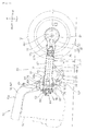
- Fig. 2 is a view for explaining a rear portion of the motorcycle according to the invention.
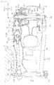
- Fig. 3 is a cross-sectional view taken along a line 3-3 in Fig. 2.
- Fig. 1 is a side view of a motorcycle according to the invention.
- the motorcycle 10 is a vehicle which is configured such that a handle 11, a front fork 12 which is steered by the handle 11 and a front wheel 13 are arranged on a front portion of a vehicle body, a vehicle body frame 14 is arranged over a center portion of the vehicle body from the front portion of the vehicle body, an engine (not shown in the drawing) is mounted on the vehicle body frame 14, a rear swing arm 17 is mounted on a lower portion of the vehicle body frame 14 in a swingable manner, and a rear wheel 19 is mounted on a rear end of the rear swing arm 17 as a vehicle wheel.
- An output of the engine is transmitted to the rear wheel 19 using a rear wheel driving mechanism (described later) which is housed in the rear swing arm 17.
- numeral 21 indicates a wind screen
- numeral 22 indicates a head lamp
- numeral 23 indicates a front fender
- numeral 24 indicates a cowling
- numeral 25 indicates a fuel tank
- numeral 26 indicates a seat
- numeral 27 indicates a luggage box
- numeral 28 indicates a main stand
- numeral 29 indicates a grab rail
- numeral 31 indicates an exhaust pipe
- numeral 32 indicates a muffler
- numeral 33 indicates a rear fender
- numeral 34 indicates a tail lamp.
- Fig. 2 is a view for explaining a rear portion of the motorcycle according to the invention.
- the motorcycle 10 includes vehicle body frames 14L, 14R (showing only the vehicle body frame 14R on a deep side), an engine 52 which is extended between the vehicle body frames 14L, 14R, a pivot shaft 15 which constitutes a support portion 16 mounted on rear portions of the vehicle body frames 14L, 14R, a rear swing arm 17 which is mounted on the pivot shaft 15 in a rockable manner, a rear wheel 19 which is pivotally supported on a rear portion of the rear swing arm 17 by way of a rear wheel shaft 18 in a rotatable manner, and a rear cushion 51 which is interposed between the rear swing arm 17 and the vehicle body frame 14.
- the motorcycle 10 includes a pair of left and right vehicle body frames 14 and a plurality of cross members which connects the pair of left and right vehicle body frames 14L, 14R (showing only the vehicle body frame 14R on a deep side) to each other, and the support portion 16 is arranged in a space defined between the upper cross member 101 and the lower cross member 102 which constitute the plurality of cross members. Accordingly, it is possible to enhance the rigidity of the vehicle body frame 14 in the vicinity of the support portion and hence, the supporting rigidity of the rear swing arm 17 can be further enhanced.
- a rear wheel driving mechanism 53 is mainly constituted of a universal joint 55 which is connected to an output shaft 54 from the engine 52 and transmits a driving force, a drive shaft 57 which is connected to a rear end 55b of a universal joint 55 and transmits the driving force of the engine 52, and a final gear unit 61 formed of a pair of a drive gear 58 and a driven gear 59 which is connected to a rear end 57b of the drive shaft 57 and transmits a driving force to the rear wheel axle 18 while converting the direction of the driving force.
- Numeral 62 indicates an output gear which is mounted on the engine 52.
- Numeral 63 indicates a transmission casing.
- the transmission casing is also used as a casing which covers the engine 52.
- Numerals 64, 65 indicate bearings which support the output shaft 54.
- the support structure of the rear swing arm 17 is constituted of a first arm member 67 which extends rearwardly from the vehicle body frames 14L, 14R (showing only the vehicle body frame 14R on a deep side) by way of a first rocking shaft 66 and is arranged in a rockable manner, a rear cushion 51 which has a lower end thereof connected to a second rocking shaft 68 which is mounted on a rear end of the first arm member 67 and has an upper end thereof connected to a fifth rocking shaft 75 which is mounted on the vehicle body frame 14, and a second arm member 72 which is extended between a third rocking shaft 69 which is mounted on a substantially intermediate portion of the first arm member 67 and a fourth rocking shaft 71 which is mounted on a substantially intermediate portion of the rear swing arm 17 and supports the rear swing arm 17.
- Numeral 76 indicates a dust boot which is arranged between the rear swing arm 17 and the transmission casing 63.
- the motorcycle 10 includes the vehicle body frame 14, the rear swing arm 17 which is mounted on the vehicle body frame 14 by way of the pivot shaft 15 in a rockable manner, and the rear wheel 19 which is pivotally supported on a rear portion 17b of the rear swing arm 17 and is rotated by a driving force of the drive shaft 57.
- the drive shaft 57 is arranged in the inside of a hollow portion 17t which is formed in the rear swing arm 17.
- the drive shaft 57 includes a shaft-length variable mechanism 77 which can change a length of a shaft on a rear end thereof. Further, a boot 78 which prevents the intrusion of foreign matters is provided to a connection portion between the shaft-length variable mechanism 77 and the drive shaft 57.
- the drive shaft 57 includes the shaft-length variable mechanism 77 which can change a length of a shaft and hence, at the time of rocking the rear swing arm 17, it is possible to absorb a movement of the drive shaft 57 in the axial direction by the shaft-length variable mechanism 77.
- the shaft-length variable mechanism 77 includes the boots 78 and hence, even when the shaft-length variable mechanism 77 is shifted in the axial direction, it is possible to hermetically seal a lubricant which is filled in the inside of the shaft-length variable mechanism 77.
- Numeral 81 indicates a final gear casing which houses the rear wheel axle 18 and drive-system parts around the rear wheel axle 18.
- pivot shaft 15 which constitutes the support portion 16 and an axis 18J of the rear wheel axle 18 are arranged at the substantially same height.
- the rear wheel drive mechanism 53 that is, the universal joint 55 or the drive shaft 57 is arranged above the pivot shaft 15.
- the support portion 16 is arranged at the substantially same height as the rear wheel axis 18J and hence, the change of a wheel base when the rear wheel 19 is rocked can be reduced whereby it is possible to obtain a favorable cushion property.
- the rear wheel drive mechanism 53 that is, the universal joint 55 or the drive shaft 57 is arranged above the support portion 16 and hence, it is possible to easily ensure a height from a ground of the rear swing arm 17.
- the drive shaft 57 is arranged at a relatively high position above the pivot shaft 15 and hence, it is possible to increase a distance between the output shaft 54 and the output gear 62 which are connected to the drive shaft 57 and the oil which is reserved in a lower portion of the engine 52 thus suppressing the agitation of the oil.
- the universal joint 55 is arranged between the output shaft 54 which extends from the engine 52 and the drive shaft 57, and the universal joint 55 is arranged directly above the pivot shaft 15 which constitutes the support portion 16 and hence, it is possible to rock the drive shaft 57 corresponding to the rocking of the rear swing arm 17.
- the universal joint 55 is arranged between the output shaft 54 which extends from the engine 52 and the drive shaft and is arranged directly above the support portion 16 and hence, it is possible to reduce the change of the relative position of the drive shaft 57 and the rear swing arm 17 which is caused by the rocking of the rear swing arm 17.
- Fig. 3 is a cross-sectional view taken along a line 3-3 in Fig. 2.
- the rear wheel drive mechanism 53 which includes the drive shaft 57 is housed in the right rear swing arm 17R and the final gear casing 81 which is arranged at the rear-swing-arm 17R side.
- the structure in the inside of the final gear casing 81 is explained.
- the structure around the rear wheel axle is mainly constituted of a sleeve 83 which is rotatably provided around the rear wheel axle 18, the driven gear 59 which is integrally mounted on a periphery of the sleeve 83, a damper holder 84 which is integrally mounted on the sleeve 83 and, at the same time, is provided in a rotatable manner relative to the rear wheel axle 18, and a damper member 87 which is interposed between the damper holder 84 and a rear-wheel wheel 85.
- the sleeve 83 is a member which connects the driven gear 59 and the damper holder 84.
- Numeral 91 indicates a bearing which supports the drive gear 58
- numerals 92a to 92c indicate bearings which support the rear wheel axle 18
- numeral 93 indicates a sealing member
- numeral 94 indicates a rear disc brake unit
- numerals 95, 96 indicate fastening nuts.
- the driving force which is applied to the driven gear 59 is transmitted to the rear-wheel wheel 85 in order of the sleeve 83, the damper holder 84, the damper member 87 and the rear-wheel wheel 85 thus driving the rear wheel 19.
- the shaft-length variable mechanism 77 is arranged at the rear portion of the rear swing arm 17R.
- the shaft-length variable mechanism 77 adopts a tripod type constant velocity universal joint 98.
- the invention is not limited to the above-mentioned embodiment, and a ball spline slide joint, a cross groove type joint or the like may be adopted. That is, provided that the joint used in this embodiment is a joint having a slide function, the structure of the joint is not limited.
- the shaft-length variable mechanism 77 is arranged on the rear portion 17b of the rear swing arm 17 and hence, it is possible to reduce the influence of heat which the shaft-length variable mechanism 77 receives from the engine (numeral 52 being shown in Fig. 2).
- the shaft-length variable mechanism 77 is arranged on the rear portion 17b of the rear swing arm 17 and hence, it is unnecessary to increase a width of the front portion 17a of the rear swing arm 17 in the lateral direction thus ensuring a rider's foot ground contact space S.
- the rear wheel drive mechanism 53 is housed in the right rear swing arm 17R.
- the rear wheel drive mechanism 53 may be housed in the left rear swing arm 17L.
- the support portion 16 which supports the rear swing arm 17 is arranged at a position spaced-apart from the drive shaft 57.
- the pivot shaft 15 is used as the support portion 16 and the pivot shaft 15 is arranged below the drive shaft 57, there is no possibility that the pivot shaft 15 and the drive shaft 57 interfere with each other. Accordingly, it is possible to increase the length of the pivot shaft 15 and hence, provided that a supporting distance between the rear swing arms 17 can be expanded, it is possible to easily ensure the supporting rigidity of the swing arm 17. Accordingly, it is no more necessary to make the rear swing arm 17 and the pivot shaft 15 large-sized thus realizing the reduction of weight of the motorcycle.
- the drive shaft 57 is arranged in the inside of a hollow portion 17t of the rear swing arm 17 and hence, it is possible to suppress the expansion of the vehicle width. Further, due to the suppression of the expansion of the vehicle width, it is possible to ensure the rider' s foot ground contact performance.
- the invention is favorably applicable to a motorcycle.
Landscapes
- Engineering & Computer Science (AREA)
- Mechanical Engineering (AREA)
- Chemical & Material Sciences (AREA)
- Combustion & Propulsion (AREA)
- Transportation (AREA)
- Axle Suspensions And Sidecars For Cycles (AREA)
- Automatic Cycles, And Cycles In General (AREA)
Abstract
Description
- The present invention relates to a motorcycle of a type which drives a rear wheel using a drive shaft.
- There has been known a motorcycle which mounts a rear swing arm on a vehicle body frame in a rockable manner by way of a support portion, pivotally supports a rear wheel on a rear portion of the rear swing arm, and includes a drive shaft which drives the rear wheel (for example, see Patent Document 1).
JP-A-2002-87364 - Fig. 4 of patent document 1 is a back view of a pivotally supporting portion of a rear arm, wherein a rear arm bracket 7 is mounted on a rear portion of a main frame 6, and a rear arm 14 (hereinafter, referred to as a rear swing arm 14) is mounted on the rear arm bracket 7 by way of a
pivot shaft 10. - The
rear swing arm 14 has a head portion 14c at a front end thereof and the head portion 14c is squeezed to have a narrow width. In the same manner, thepivot shaft 10 is also formed with a small length. Such a constitution is necessary for arranging a universal joint portion 42 (hereinafter, referred to as the universal joint 42) on a side of thepivot shaft 10. - With respect to a twisting force which acts on the
rear swing arm 14, the larger the width of the head portion 14c or the larger the length of thepivot shaft 10, it is possible to increase the supporting rigidity.
In this respect, the head portion 14c has the small width and thepivot shaft 10 is short in patent document 1 and hence, it is necessary for therear swing arm 14 to increase the diameter of the head portion 14c or the diameter of thepivot shaft 10 to ensure the supporting rigidity. As a result, the weight of theswing arm 14 is increased.
It is an object of the invention to provide a motorcycle which can be made light-weighted while easily ensuring the supporting rigidity of a rear swing arm. - The invention according to claim 1 is characterized in that, in a motorcycle which includes a vehicle body frame, a rear swing arm which is mounted on the vehicle body frame in a rockable manner by way of a support portion, and a rear wheel which is pivotally supported on a rear portion of the rear swing arm and is rotated by a driving force of a drive shaft, the support portion is arranged at a position spaced-apart from the drive shaft as viewed from a side view of the vehicle body.
- The invention according to claim 2 is characterized in that the support portion is arranged at a substantially same height as an axis of the rear wheel, and the drive shaft is arranged above the support portion.
- The invention according to claim 3 is characterized in that a universal joint is arranged between an output shaft which extends from the engine and the drive shaft, and the universal joint is arranged directly above the support portion.
- The invention according to claim 4 is characterized in that the drive shaft adopts a shaft-length variable mechanism which can change a shaft length, and the shaft-length variable mechanism includes a boot which can prevent an intrusion of foreign matters.
- The invention according to claim 5 is characterized in that the shaft-length variable mechanism is arranged at the rear portion of the rear swing arm.
- The invention according to claim 6 is characterized in that the motorcycle includes a pair of left and right vehicle body frames and a plurality of cross members which connects the pair of left and right vehicle body frames to each other, and the support portion is arranged in a space defined between the plurality of cross members.
- According to the invention described in claim 1, the support portion is arranged at a position spaced-apart from the drive shaft as viewed in a side view of the vehicle body and hence, it is possible to increase a length of the support portion without generating an interference between the support portion and the drive shaft thus easily ensuring the supporting rigidity of the rear swing arm.
Accordingly, it is unnecessary to make the rear swing arm or the support portion large-sized thus realizing the reduction of weight of the motorcycle. - According to the invention described in claim 2, the support portion is arranged at the substantially same height as the axis of the rear wheel and hence, it is possible to obtain the favorable cushion property. Further, the drive shaft is arranged above the support portion and hence, it is possible to easily ensure a height above a ground of the rear swing arm.
- According to the invention described in claim 3, the universal joint is arranged between the output shaft which extends from the engine and the drive shaft and hence, it is possible to rock the drive shaft corresponding to the rocking of the rear swing arm.
Further, the universal joint is arranged between the output shaft which extends from the engine and the drive shaft and is arranged directly above the support portion and hence, it is possible to decrease a change of a relative position of the drive shaft and the rear swing arm which is caused by the rocking of the rear swing arm. - According to the invention described in claim 4, the drive shaft adopts a shaft-length variable mechanism which can change a shaft length and hence, at the time of rocking the rear swing arm, it is possible to absorb the movement of the drive shaft in the axial direction using the joint.
Further, the shaft-length variable mechanism includes the boot and hence, even when the shaft-length variable mechanism is shifted in the axial direction, it is possible to seal oil which is filled in the inside of the shaft-length variable mechanism. - According to the invention described in claim 5, the shaft-length variable mechanism is arranged at the rear portion of the rear swing arm and hence, it is possible to decrease the influence of heat which the shaft-length variable mechanism receives from the engine. Further, the shaft-length variable mechanism is arranged at a rear portion of the rear swing arm and hence, it is unnecessary to expand a front portion of the rear swing arm in the lateral direction whereby a rider can surely place his foot on a ground.
- According to the invention described in claim 6, the support portion is arranged in the space which is defined between the plurality of cross members and hence, it is possible to enhance the rigidity of the vehicle body frame in the vicinity of the support portion. Accordingly, it is possible to further enhance the supporting rigidity of the rear swing arm.
Fig. 1 is a side view of a motorcycle according to the invention.
Fig. 2 is a view for explaining a rear portion of the motorcycle according to the invention.
Fig. 3 is a cross-sectional view taken along a line 3-3 in Fig. 2. - Hereinafter, a best mode for carrying out the invention is explained in conjunction with attached drawings. Here, the drawings are viewed in the same direction as numerals.
Fig. 1 is a side view of a motorcycle according to the invention. Themotorcycle 10 is a vehicle which is configured such that ahandle 11, afront fork 12 which is steered by thehandle 11 and afront wheel 13 are arranged on a front portion of a vehicle body, avehicle body frame 14 is arranged over a center portion of the vehicle body from the front portion of the vehicle body, an engine (not shown in the drawing) is mounted on thevehicle body frame 14, arear swing arm 17 is mounted on a lower portion of thevehicle body frame 14 in a swingable manner, and arear wheel 19 is mounted on a rear end of therear swing arm 17 as a vehicle wheel.
An output of the engine is transmitted to therear wheel 19 using a rear wheel driving mechanism (described later) which is housed in therear swing arm 17. - Here,
numeral 21 indicates a wind screen,numeral 22 indicates a head lamp,numeral 23 indicates a front fender,numeral 24 indicates a cowling,numeral 25 indicates a fuel tank,numeral 26 indicates a seat,numeral 27 indicates a luggage box,numeral 28 indicates a main stand,numeral 29 indicates a grab rail,numeral 31 indicates an exhaust pipe,numeral 32 indicates a muffler,numeral 33 indicates a rear fender andnumeral 34 indicates a tail lamp. - Fig. 2 is a view for explaining a rear portion of the motorcycle according to the invention. The
motorcycle 10 includesvehicle body frames 14L, 14R (showing only the vehicle body frame 14R on a deep side), anengine 52 which is extended between thevehicle body frames 14L, 14R, apivot shaft 15 which constitutes asupport portion 16 mounted on rear portions of thevehicle body frames 14L, 14R, arear swing arm 17 which is mounted on thepivot shaft 15 in a rockable manner, arear wheel 19 which is pivotally supported on a rear portion of therear swing arm 17 by way of arear wheel shaft 18 in a rotatable manner, and a rear cushion 51 which is interposed between therear swing arm 17 and thevehicle body frame 14. - The
motorcycle 10 includes a pair of left and rightvehicle body frames 14 and a plurality of cross members which connects the pair of left and rightvehicle body frames 14L, 14R (showing only the vehicle body frame 14R on a deep side) to each other, and thesupport portion 16 is arranged in a space defined between theupper cross member 101 and thelower cross member 102 which constitute the plurality of cross members.
Accordingly, it is possible to enhance the rigidity of thevehicle body frame 14 in the vicinity of the support portion and hence, the supporting rigidity of therear swing arm 17 can be further enhanced. - A rear
wheel driving mechanism 53 is mainly constituted of auniversal joint 55 which is connected to anoutput shaft 54 from theengine 52 and transmits a driving force, adrive shaft 57 which is connected to arear end 55b of auniversal joint 55 and transmits the driving force of theengine 52, and afinal gear unit 61 formed of a pair of adrive gear 58 and a drivengear 59 which is connected to arear end 57b of thedrive shaft 57 and transmits a driving force to therear wheel axle 18 while converting the direction of the driving force.Numeral 62 indicates an output gear which is mounted on theengine 52. - Numeral 63 indicates a transmission casing. In this embodiment, the transmission casing is also used as a casing which covers the
engine 52.Numerals output shaft 54. - The support structure of the
rear swing arm 17 is constituted of afirst arm member 67 which extends rearwardly from thevehicle body frames 14L, 14R (showing only the vehicle body frame 14R on a deep side) by way of afirst rocking shaft 66 and is arranged in a rockable manner, a rear cushion 51 which has a lower end thereof connected to a second rockingshaft 68 which is mounted on a rear end of thefirst arm member 67 and has an upper end thereof connected to a fifth rocking shaft 75 which is mounted on thevehicle body frame 14, and asecond arm member 72 which is extended between a third rockingshaft 69 which is mounted on a substantially intermediate portion of thefirst arm member 67 and afourth rocking shaft 71 which is mounted on a substantially intermediate portion of therear swing arm 17 and supports therear swing arm 17. Numeral 76 indicates a dust boot which is arranged between therear swing arm 17 and the transmission casing 63. - That is, the
motorcycle 10 includes thevehicle body frame 14, therear swing arm 17 which is mounted on thevehicle body frame 14 by way of thepivot shaft 15 in a rockable manner, and therear wheel 19 which is pivotally supported on arear portion 17b of therear swing arm 17 and is rotated by a driving force of thedrive shaft 57. Thedrive shaft 57 is arranged in the inside of ahollow portion 17t which is formed in therear swing arm 17. - The
drive shaft 57 includes a shaft-lengthvariable mechanism 77 which can change a length of a shaft on a rear end thereof. Further, aboot 78 which prevents the intrusion of foreign matters is provided to a connection portion between the shaft-lengthvariable mechanism 77 and thedrive shaft 57.
Thedrive shaft 57 includes the shaft-lengthvariable mechanism 77 which can change a length of a shaft and hence, at the time of rocking therear swing arm 17, it is possible to absorb a movement of thedrive shaft 57 in the axial direction by the shaft-lengthvariable mechanism 77. - Further, the shaft-length
variable mechanism 77 includes theboots 78 and hence, even when the shaft-length variable mechanism 77 is shifted in the axial direction, it is possible to hermetically seal a lubricant which is filled in the inside of the shaft-lengthvariable mechanism 77.
Numeral 81 indicates a final gear casing which houses therear wheel axle 18 and drive-system parts around therear wheel axle 18. - Further, the
pivot shaft 15 which constitutes thesupport portion 16 and anaxis 18J of therear wheel axle 18 are arranged at the substantially same height. The rearwheel drive mechanism 53, that is, theuniversal joint 55 or thedrive shaft 57 is arranged above thepivot shaft 15. - The
support portion 16 is arranged at the substantially same height as therear wheel axis 18J and hence, the change of a wheel base when therear wheel 19 is rocked can be reduced whereby it is possible to obtain a favorable cushion property. Further, the rearwheel drive mechanism 53, that is, theuniversal joint 55 or thedrive shaft 57 is arranged above thesupport portion 16 and hence, it is possible to easily ensure a height from a ground of therear swing arm 17. - Further, the
drive shaft 57 is arranged at a relatively high position above thepivot shaft 15 and hence, it is possible to increase a distance between theoutput shaft 54 and theoutput gear 62 which are connected to thedrive shaft 57 and the oil which is reserved in a lower portion of theengine 52 thus suppressing the agitation of the oil. - Still further, the
universal joint 55 is arranged between theoutput shaft 54 which extends from theengine 52 and thedrive shaft 57, and theuniversal joint 55 is arranged directly above thepivot shaft 15 which constitutes thesupport portion 16 and hence, it is possible to rock thedrive shaft 57 corresponding to the rocking of therear swing arm 17. - In addition, the
universal joint 55 is arranged between theoutput shaft 54 which extends from theengine 52 and the drive shaft and is arranged directly above thesupport portion 16 and hence, it is possible to reduce the change of the relative position of thedrive shaft 57 and therear swing arm 17 which is caused by the rocking of therear swing arm 17. - Fig. 3 is a cross-sectional view taken along a line 3-3 in Fig. 2. In Fig. 3, the rear
wheel drive mechanism 53 which includes thedrive shaft 57 is housed in the rightrear swing arm 17R and thefinal gear casing 81 which is arranged at the rear-swing-arm 17R side. Hereinafter, the structure in the inside of thefinal gear casing 81 is explained. - The structure around the rear wheel axle is mainly constituted of a
sleeve 83 which is rotatably provided around therear wheel axle 18, the drivengear 59 which is integrally mounted on a periphery of thesleeve 83, adamper holder 84 which is integrally mounted on thesleeve 83 and, at the same time, is provided in a rotatable manner relative to therear wheel axle 18, and adamper member 87 which is interposed between thedamper holder 84 and a rear-wheel wheel 85. That is, thesleeve 83 is a member which connects the drivengear 59 and thedamper holder 84.
Numeral 91 indicates a bearing which supports thedrive gear 58, numerals 92a to 92c indicate bearings which support therear wheel axle 18, numeral 93 indicates a sealing member, numeral 94 indicates a rear disc brake unit, andnumerals - Due to the constitution around the rear wheel axle, the driving force which is applied to the driven
gear 59 is transmitted to the rear-wheel wheel 85 in order of thesleeve 83, thedamper holder 84, thedamper member 87 and the rear-wheel wheel 85 thus driving therear wheel 19. - The shaft-
length variable mechanism 77 is arranged at the rear portion of therear swing arm 17R.
In this embodiment, the shaft-length variable mechanism 77 adopts a tripod type constant velocity universal joint 98. However, the invention is not limited to the above-mentioned embodiment, and a ball spline slide joint, a cross groove type joint or the like may be adopted. That is, provided that the joint used in this embodiment is a joint having a slide function, the structure of the joint is not limited. - The shaft-
length variable mechanism 77 is arranged on therear portion 17b of therear swing arm 17 and hence, it is possible to reduce the influence of heat which the shaft-length variable mechanism 77 receives from the engine (numeral 52 being shown in Fig. 2). In addition, the shaft-length variable mechanism 77 is arranged on therear portion 17b of therear swing arm 17 and hence, it is unnecessary to increase a width of thefront portion 17a of therear swing arm 17 in the lateral direction thus ensuring a rider's foot ground contact space S. - In this embodiment, the rear
wheel drive mechanism 53 is housed in the rightrear swing arm 17R. However, the rearwheel drive mechanism 53 may be housed in the leftrear swing arm 17L. - Next, the manner of operation of the motorcycle having the rear swing arm support structure which is described above is explained.
Thesupport portion 16 which supports therear swing arm 17 is arranged at a position spaced-apart from thedrive shaft 57. For example, since thepivot shaft 15 is used as thesupport portion 16 and thepivot shaft 15 is arranged below thedrive shaft 57, there is no possibility that thepivot shaft 15 and thedrive shaft 57 interfere with each other. Accordingly, it is possible to increase the length of thepivot shaft 15 and hence, provided that a supporting distance between therear swing arms 17 can be expanded, it is possible to easily ensure the supporting rigidity of theswing arm 17.
Accordingly, it is no more necessary to make therear swing arm 17 and thepivot shaft 15 large-sized thus realizing the reduction of weight of the motorcycle. - In addition, the
drive shaft 57 is arranged in the inside of ahollow portion 17t of therear swing arm 17 and hence, it is possible to suppress the expansion of the vehicle width. Further, due to the suppression of the expansion of the vehicle width, it is possible to ensure the rider' s foot ground contact performance. - The invention is favorably applicable to a motorcycle.
- 10: motorcycle
- 14, 14L, 14R: vehicle body frame
- 16: support portion
- 17, 17L, 17R: rear swing arm
- 18J: rear wheel axis
- 19: rear wheel
- 54: output shaft which extends from engine
- 55: universal joint
- 57: drive shaft
- 77: shaft length variable mechanism
- 78: boots
- 101: upper cross member
- 102: lower cross member
Claims (6)
- A motorcycle (10) which includes a vehicle body frame (14), a rear swing arm (17) which is mounted on the vehicle body frame (14) in a rockable manner by way of a support portion (16), and a rear wheel (19) which is pivotally supported on a rear portion of the rear swing arm (17) and is rotated by a driving force of a drive shaft (57), wherein
the support portion (16) is arranged at a position spaced-apart from the drive shaft as viewed in a side view of the vehicle body. - A motorcycle (10) according to claim 1, wherein the support portion (16) is arranged at a substantially same height as an axis of the rear wheel (19), and the drive shaft (57) is arranged above the support portion (16).
- A motorcycle (10) according to any of the preceding claims, wherein a universal joint (55) is arranged between an output shaft which extends from the engine (54) and the drive shaft (57), and the universal joint (55) is arranged directly above the support portion (16).
- A motorcycle (10) according to any of the preceding claims, wherein the drive shaft (57) adopts a shaft-length variable mechanism (77) which can change a shaft length, and the shaft-length variable mechanism includes a boot (78) which prevents an intrusion of foreign matters.
- A motorcycle (10) according to any of the preceding claims, wherein the shaft-length variable mechanism (77) is arranged at the rear portion of the rear swing arm (17).
- A motorcycle (10) according to any of the preceding claims, wherein the motorcycle (10) includes a pair of left and right vehicle body frames (14) and a plurality of cross members which connects the pair of left and right vehicle body frames (14) to each other, and the support portion is arranged in a space which is defined between the plurality of cross members.
Applications Claiming Priority (1)
| Application Number | Priority Date | Filing Date | Title |
|---|---|---|---|
| JP2006054128A JP4733538B2 (en) | 2006-02-28 | 2006-02-28 | Motorcycle |
Publications (2)
| Publication Number | Publication Date |
|---|---|
| EP1826110A1 true EP1826110A1 (en) | 2007-08-29 |
| EP1826110B1 EP1826110B1 (en) | 2008-08-27 |
Family
ID=37831486
Family Applications (1)
| Application Number | Title | Priority Date | Filing Date |
|---|---|---|---|
| EP07101086A Not-in-force EP1826110B1 (en) | 2006-02-28 | 2007-01-24 | Motorcycle with drive shaft |
Country Status (5)
| Country | Link |
|---|---|
| US (1) | US7644797B2 (en) |
| EP (1) | EP1826110B1 (en) |
| JP (1) | JP4733538B2 (en) |
| DE (1) | DE602007000092D1 (en) |
| ES (1) | ES2312154T3 (en) |
Cited By (3)
| Publication number | Priority date | Publication date | Assignee | Title |
|---|---|---|---|---|
| ITMI20082082A1 (en) * | 2008-11-21 | 2010-05-22 | Piaggio & C Spa | SHAFT TRANSMISSION SYSTEM FOR MOTOR VEHICLES |
| DE102008039578B4 (en) * | 2007-08-27 | 2011-04-28 | Honda Motor Co., Ltd. | motorcycle |
| ITUB20155573A1 (en) * | 2015-11-13 | 2017-05-13 | Pierobon 1952 S R L | REAR SUSPENSION SYSTEM FOR A MOTORCYCLE AND ITS MOTORCYCLE |
Families Citing this family (20)
| Publication number | Priority date | Publication date | Assignee | Title |
|---|---|---|---|---|
| JP4240010B2 (en) * | 2005-06-16 | 2009-03-18 | トヨタ自動車株式会社 | Vehicle stabilizer system |
| JP4532380B2 (en) * | 2005-09-29 | 2010-08-25 | 本田技研工業株式会社 | Motorcycle |
| JP4814739B2 (en) * | 2006-09-20 | 2011-11-16 | 本田技研工業株式会社 | Motorcycle |
| JP4394117B2 (en) * | 2006-12-28 | 2010-01-06 | 本田技研工業株式会社 | Swing arm structure for shaft drive vehicle |
| JP4994071B2 (en) * | 2007-03-20 | 2012-08-08 | 本田技研工業株式会社 | Motorcycle shaft drive device |
| JP5117227B2 (en) * | 2008-03-12 | 2013-01-16 | 本田技研工業株式会社 | Motorcycle |
| JP5086850B2 (en) * | 2008-03-13 | 2012-11-28 | 本田技研工業株式会社 | vehicle |
| JP5086855B2 (en) * | 2008-03-18 | 2012-11-28 | 本田技研工業株式会社 | Motorcycle |
| US8297398B2 (en) * | 2008-08-11 | 2012-10-30 | Honda Motor Co., Ltd. | Two-wheeled motor vehicle |
| JP5123806B2 (en) * | 2008-09-30 | 2013-01-23 | 本田技研工業株式会社 | Shaft drive motorcycle |
| JP2010221885A (en) * | 2009-03-24 | 2010-10-07 | Honda Motor Co Ltd | Motorcycle |
| JP2012096613A (en) * | 2010-10-29 | 2012-05-24 | Honda Motor Co Ltd | Electric vehicle |
| CN102923237A (en) * | 2012-11-21 | 2013-02-13 | 力帆实业(集团)股份有限公司 | Cradle type rear cushion mechanism of motorcycle |
| JP2014181007A (en) * | 2013-03-21 | 2014-09-29 | Yamaha Motor Co Ltd | Motorcycle |
| ITPD20130309A1 (en) * | 2013-11-14 | 2015-05-15 | Piaggio & C Spa | MOTORCYCLE TRANSMISSION OF HOMOCINETARY TYPE, AND MOTORCYCLE INCLUDING THE TRANSMISSION |
| JP2015209099A (en) * | 2014-04-25 | 2015-11-24 | 本田技研工業株式会社 | Rear wheel suspension structure of motor cycle |
| JP6009503B2 (en) * | 2014-07-31 | 2016-10-19 | 本田技研工業株式会社 | Link mechanism protection structure for saddle-ride type vehicles |
| ITUB20153985A1 (en) * | 2015-09-29 | 2017-03-29 | Piaggio & C Spa | MOTORCYCLE RETRO BACK WITH CARDANIC TRANSMISSION AND MOTORCYCLE RELATIVE |
| US10875595B2 (en) | 2016-01-29 | 2020-12-29 | Bombardier Recreational Products Inc. | Three-wheeled straddle-seat vehicle |
| EP3661772A4 (en) | 2017-07-31 | 2020-07-15 | Bombardier Recreational Products Inc. | Suspension assembly for a vehicle |
Citations (2)
| Publication number | Priority date | Publication date | Assignee | Title |
|---|---|---|---|---|
| JP2003191886A (en) * | 2001-10-16 | 2003-07-09 | Honda Motor Co Ltd | Swing arm structure |
| EP1486411A2 (en) * | 2003-06-12 | 2004-12-15 | HONDA MOTOR CO., Ltd. | Pivot shaft structure for supporting swing arm |
Family Cites Families (16)
| Publication number | Priority date | Publication date | Assignee | Title |
|---|---|---|---|---|
| JPS5546045A (en) * | 1978-09-29 | 1980-03-31 | Yamaha Motor Co Ltd | Muffler for autobicycle |
| DE8017869U1 (en) * | 1980-07-03 | 1981-02-19 | Bayerische Motoren Werke Ag, 8000 Muenchen | TWO-WHEELED VEHICLE WITH A DRIVE DRIVE IN A REAR WHEEL GUIDE |
| JPS58101825A (en) * | 1981-12-11 | 1983-06-17 | Yamaha Motor Co Ltd | Autobicycle mounted with v-type engine |
| JPS616431A (en) * | 1984-06-21 | 1986-01-13 | Honda Motor Co Ltd | propeller shaft |
| US4660854A (en) * | 1984-12-18 | 1987-04-28 | Yamaha Hatsudoki Kabushiki Kaisha | Frame construction for motorcycles |
| JP2718528B2 (en) * | 1988-11-25 | 1998-02-25 | 本田技研工業株式会社 | Vehicle power plant |
| US5067580A (en) * | 1988-05-20 | 1991-11-26 | James Parker | Anti-shaft effect motorcycle suspension |
| US5263549A (en) * | 1992-12-07 | 1993-11-23 | Dick David R | Motorcycle shaft drive mechanism |
| JPH09112565A (en) * | 1995-10-18 | 1997-05-02 | Honda Motor Co Ltd | Driven force transmission structure for four-wheel drive vehicle |
| JP3902385B2 (en) * | 2000-06-27 | 2007-04-04 | 本田技研工業株式会社 | Swing arm for vehicle |
| JP4557109B2 (en) | 2000-09-12 | 2010-10-06 | ヤマハ発動機株式会社 | Motorcycle |
| ATE348033T1 (en) * | 2002-05-03 | 2007-01-15 | Moto Guzzi S P A | REAR AXLE FOR SHAFT DRIVE MOTORCYCLES |
| JP2006096273A (en) * | 2004-09-30 | 2006-04-13 | Honda Motor Co Ltd | Rear wheel support structure for motorcycles and tricycles |
| JP4459002B2 (en) * | 2004-09-30 | 2010-04-28 | 本田技研工業株式会社 | Motorcycle |
| US7665563B2 (en) * | 2005-01-11 | 2010-02-23 | Honda Motor Co., Ltd. | Swing arm supporting structure for motorcycles |
| JP4532380B2 (en) * | 2005-09-29 | 2010-08-25 | 本田技研工業株式会社 | Motorcycle |
-
2006
- 2006-02-28 JP JP2006054128A patent/JP4733538B2/en not_active Expired - Fee Related
-
2007
- 2007-01-24 EP EP07101086A patent/EP1826110B1/en not_active Not-in-force
- 2007-01-24 DE DE602007000092T patent/DE602007000092D1/en active Active
- 2007-01-24 ES ES07101086T patent/ES2312154T3/en active Active
- 2007-02-23 US US11/709,678 patent/US7644797B2/en active Active
Patent Citations (2)
| Publication number | Priority date | Publication date | Assignee | Title |
|---|---|---|---|---|
| JP2003191886A (en) * | 2001-10-16 | 2003-07-09 | Honda Motor Co Ltd | Swing arm structure |
| EP1486411A2 (en) * | 2003-06-12 | 2004-12-15 | HONDA MOTOR CO., Ltd. | Pivot shaft structure for supporting swing arm |
Cited By (3)
| Publication number | Priority date | Publication date | Assignee | Title |
|---|---|---|---|---|
| DE102008039578B4 (en) * | 2007-08-27 | 2011-04-28 | Honda Motor Co., Ltd. | motorcycle |
| ITMI20082082A1 (en) * | 2008-11-21 | 2010-05-22 | Piaggio & C Spa | SHAFT TRANSMISSION SYSTEM FOR MOTOR VEHICLES |
| ITUB20155573A1 (en) * | 2015-11-13 | 2017-05-13 | Pierobon 1952 S R L | REAR SUSPENSION SYSTEM FOR A MOTORCYCLE AND ITS MOTORCYCLE |
Also Published As
| Publication number | Publication date |
|---|---|
| US7644797B2 (en) | 2010-01-12 |
| DE602007000092D1 (en) | 2008-10-09 |
| US20070199756A1 (en) | 2007-08-30 |
| EP1826110B1 (en) | 2008-08-27 |
| JP2007230354A (en) | 2007-09-13 |
| ES2312154T3 (en) | 2009-02-16 |
| JP4733538B2 (en) | 2011-07-27 |
Similar Documents
| Publication | Publication Date | Title |
|---|---|---|
| EP1826110B1 (en) | Motorcycle with drive shaft | |
| US7913793B2 (en) | Shaft-driven motorcycle with pivotally mounted swing arm and related support structure | |
| US7946374B2 (en) | Vehicle | |
| JP2001328410A (en) | Saddle-riding vehicle | |
| US11130541B2 (en) | Saddle type vehicle | |
| CA2560412C (en) | Shaft-driven motorcycle swing arm arrangement | |
| US20040188167A1 (en) | Reinforcing support structure for a three-wheeled motor vehicle, and three-wheeled motor vehicle incorporating same | |
| US7717213B2 (en) | Motorcycle | |
| JP4558432B2 (en) | Swing arm structure | |
| JP6251615B2 (en) | Suspension device for saddle riding type vehicle | |
| US20170101156A1 (en) | Saddle-type vehicle | |
| US8413755B2 (en) | Motorcycle | |
| JP5111874B2 (en) | Cushion support structure | |
| JP4833903B2 (en) | Rear structure of motorcycle | |
| JP2008179323A (en) | Suspension arm structure | |
| JP2008087585A (en) | Motorcycle rear wheel drive system | |
| JP2008074215A (en) | Motorcycle rear wheel drive system | |
| JPH08216962A (en) | Suspension structure of shaft drive type bicycle | |
| JPH09249177A (en) | Rear wheel suspension for scooters | |
| JP2009234347A (en) | Wheel support structure | |
| JPH0995281A (en) | Front wheel suspension system for motorcycles | |
| JP2008247337A (en) | Front cushion structure of motorcycle | |
| JP2008143270A (en) | Trailing arm suspension structure |
Legal Events
| Date | Code | Title | Description |
|---|---|---|---|
| PUAI | Public reference made under article 153(3) epc to a published international application that has entered the european phase |
Free format text: ORIGINAL CODE: 0009012 |
|
| 17P | Request for examination filed |
Effective date: 20070124 |
|
| AK | Designated contracting states |
Kind code of ref document: A1 Designated state(s): AT BE BG CH CY CZ DE DK EE ES FI FR GB GR HU IE IS IT LI LT LU LV MC NL PL PT RO SE SI SK TR |
|
| AX | Request for extension of the european patent |
Extension state: AL BA HR MK YU |
|
| GRAP | Despatch of communication of intention to grant a patent |
Free format text: ORIGINAL CODE: EPIDOSNIGR1 |
|
| GRAS | Grant fee paid |
Free format text: ORIGINAL CODE: EPIDOSNIGR3 |
|
| AKX | Designation fees paid |
Designated state(s): DE ES IT |
|
| GRAA | (expected) grant |
Free format text: ORIGINAL CODE: 0009210 |
|
| AK | Designated contracting states |
Kind code of ref document: B1 Designated state(s): DE ES IT |
|
| REF | Corresponds to: |
Ref document number: 602007000092 Country of ref document: DE Date of ref document: 20081009 Kind code of ref document: P |
|
| REG | Reference to a national code |
Ref country code: ES Ref legal event code: FG2A Ref document number: 2312154 Country of ref document: ES Kind code of ref document: T3 |
|
| PLBE | No opposition filed within time limit |
Free format text: ORIGINAL CODE: 0009261 |
|
| STAA | Information on the status of an ep patent application or granted ep patent |
Free format text: STATUS: NO OPPOSITION FILED WITHIN TIME LIMIT |
|
| 26N | No opposition filed |
Effective date: 20090528 |
|
| PGRI | Patent reinstated in contracting state [announced from national office to epo] |
Ref country code: IT Effective date: 20110501 |
|
| PGFP | Annual fee paid to national office [announced via postgrant information from national office to epo] |
Ref country code: ES Payment date: 20141211 Year of fee payment: 9 |
|
| PGFP | Annual fee paid to national office [announced via postgrant information from national office to epo] |
Ref country code: IT Payment date: 20160127 Year of fee payment: 10 |
|
| REG | Reference to a national code |
Ref country code: DE Ref legal event code: R084 Ref document number: 602007000092 Country of ref document: DE |
|
| PG25 | Lapsed in a contracting state [announced via postgrant information from national office to epo] |
Ref country code: IT Free format text: LAPSE BECAUSE OF NON-PAYMENT OF DUE FEES Effective date: 20170124 |
|
| PG25 | Lapsed in a contracting state [announced via postgrant information from national office to epo] |
Ref country code: ES Free format text: LAPSE BECAUSE OF NON-PAYMENT OF DUE FEES Effective date: 20160125 |
|
| REG | Reference to a national code |
Ref country code: ES Ref legal event code: FD2A Effective date: 20181207 |
|
| PGFP | Annual fee paid to national office [announced via postgrant information from national office to epo] |
Ref country code: DE Payment date: 20210112 Year of fee payment: 15 |
|
| REG | Reference to a national code |
Ref country code: DE Ref legal event code: R119 Ref document number: 602007000092 Country of ref document: DE |
|
| PG25 | Lapsed in a contracting state [announced via postgrant information from national office to epo] |
Ref country code: DE Free format text: LAPSE BECAUSE OF NON-PAYMENT OF DUE FEES Effective date: 20220802 |