EP1826097A1 - Electric power steering apparatus - Google Patents
Electric power steering apparatus Download PDFInfo
- Publication number
- EP1826097A1 EP1826097A1 EP07003590A EP07003590A EP1826097A1 EP 1826097 A1 EP1826097 A1 EP 1826097A1 EP 07003590 A EP07003590 A EP 07003590A EP 07003590 A EP07003590 A EP 07003590A EP 1826097 A1 EP1826097 A1 EP 1826097A1
- Authority
- EP
- European Patent Office
- Prior art keywords
- torque signal
- reference voltage
- torque
- sub
- monitoring portion
- Prior art date
- Legal status (The legal status is an assumption and is not a legal conclusion. Google has not performed a legal analysis and makes no representation as to the accuracy of the status listed.)
- Withdrawn
Links
- 238000001514 detection method Methods 0.000 claims abstract description 152
- 238000012544 monitoring process Methods 0.000 claims abstract description 111
- 230000002159 abnormal effect Effects 0.000 claims abstract description 48
- 238000012360 testing method Methods 0.000 claims abstract description 19
- 230000008859 change Effects 0.000 claims description 7
- 230000005856 abnormality Effects 0.000 description 74
- 238000000034 method Methods 0.000 description 21
- 230000008569 process Effects 0.000 description 21
- 238000004092 self-diagnosis Methods 0.000 description 20
- 230000006870 function Effects 0.000 description 8
- 238000010586 diagram Methods 0.000 description 6
- 230000002093 peripheral effect Effects 0.000 description 4
- 238000003745 diagnosis Methods 0.000 description 3
- 238000011161 development Methods 0.000 description 2
- 238000004519 manufacturing process Methods 0.000 description 2
- 230000004048 modification Effects 0.000 description 2
- 238000012986 modification Methods 0.000 description 2
- 230000008439 repair process Effects 0.000 description 2
- 230000002708 enhancing effect Effects 0.000 description 1
- 238000012423 maintenance Methods 0.000 description 1
- 230000002265 prevention Effects 0.000 description 1
- 230000009467 reduction Effects 0.000 description 1
Images




Classifications
-
- B—PERFORMING OPERATIONS; TRANSPORTING
- B62—LAND VEHICLES FOR TRAVELLING OTHERWISE THAN ON RAILS
- B62D—MOTOR VEHICLES; TRAILERS
- B62D5/00—Power-assisted or power-driven steering
- B62D5/04—Power-assisted or power-driven steering electrical, e.g. using an electric servo-motor connected to, or forming part of, the steering gear
- B62D5/0457—Power-assisted or power-driven steering electrical, e.g. using an electric servo-motor connected to, or forming part of, the steering gear characterised by control features of the drive means as such
- B62D5/0481—Power-assisted or power-driven steering electrical, e.g. using an electric servo-motor connected to, or forming part of, the steering gear characterised by control features of the drive means as such monitoring the steering system, e.g. failures
- B62D5/049—Power-assisted or power-driven steering electrical, e.g. using an electric servo-motor connected to, or forming part of, the steering gear characterised by control features of the drive means as such monitoring the steering system, e.g. failures detecting sensor failures
-
- B—PERFORMING OPERATIONS; TRANSPORTING
- B62—LAND VEHICLES FOR TRAVELLING OTHERWISE THAN ON RAILS
- B62D—MOTOR VEHICLES; TRAILERS
- B62D6/00—Arrangements for automatically controlling steering depending on driving conditions sensed and responded to, e.g. control circuits
- B62D6/08—Arrangements for automatically controlling steering depending on driving conditions sensed and responded to, e.g. control circuits responsive only to driver input torque
- B62D6/10—Arrangements for automatically controlling steering depending on driving conditions sensed and responded to, e.g. control circuits responsive only to driver input torque characterised by means for sensing or determining torque
-
- G—PHYSICS
- G01—MEASURING; TESTING
- G01L—MEASURING FORCE, STRESS, TORQUE, WORK, MECHANICAL POWER, MECHANICAL EFFICIENCY, OR FLUID PRESSURE
- G01L25/00—Testing or calibrating of apparatus for measuring force, torque, work, mechanical power, or mechanical efficiency
- G01L25/003—Testing or calibrating of apparatus for measuring force, torque, work, mechanical power, or mechanical efficiency for measuring torque
Definitions
- This invention relates to an electric power steering apparatus and, more particularly, to an electric power steering apparatus enabled to detect a failure of a torque sensor incorporated in an electric power steering apparatus, especially, a failure of a shortcircuit of a pair of detection coils detecting steering torque.
- a non-contact torque sensor having a torque detection portion adapted to convert twist motion of a torsion bar, which is proportional to steering torque, into change in inductance of a pair of detection coils, a bridge circuit configured by a pair of detection coils and a pair of resistors to output a detection signal corresponding to change in the inductance, a main torque amplifier amplifying a main torque signal outputted by the bridge circuit, and a sub torque amplifier amplifying a sub torque signal outputted by the bridge circuit.
- the electric power steering apparatus To enhance the fail safe function of the torque sensor, it has been desired to configure the electric power steering apparatus to automatically perform periodical operation tests on the torque sensor at every lapse of a predetermined period, for example, at initial diagnosis of a control unit of the electricpower steering apparatus after an ignition key is turned to an ON-position, or during an operating state.
- the torque sensor has a drawback in that torque cannot accurately be detected, especially, at occurrence of an abnormality, for example, at reduction in the amplitude of an AC voltage signal supplied to the bridge circuit constituted by a pair of detection coils and a pair of resistors in the torque sensor for some cause.
- FIG. 6 is a block diagram illustrating the configurations of the conventional torque detection circuit 100 and a peripheral circuit incorporated in a control circuit 200 that controls an electric power steering apparatus (not shown) associated with the torque detection circuit 100.
- An AC voltage V osc is supplied to a bridge circuit constituted by a first arm, which has a detection coil L1 and a resistor R1, and a second arm having a detection coil L2 and a resistor R2.
- a main torque signal V tm is obtained by amplifying a differential voltage V def and a voltage outputted from the connecting part between the detection coil L2 and the resistor R2 of the second arm through a main torque amplifying circuit.
- the differential voltage V def represents the difference between a voltage outputted from the connecting part between the detection coil L1 and the resistor R1 of the first arm. Additionally, a sub torque signal V ts is obtained by amplifying the differential voltage V def through a sub torque amplifying circuit.
- the torque detection circuit 100 is configured so that an abnormality thereof is detected by comparing the detected main torque signal V tm with the detected sub torque signal V ts at an abnormality detection portion 105, and that when an abnormality is detected, the torque detection circuit 100 outputs an abnormality detection signal to change a mode of an electric power steering apparatus into a fail safe mode.
- different reference voltages are supplied to a monitoring portion 103 from a reference voltage generation circuit (not shown).
- the monitoring portion 103 monitors whether an abnormality of the amplitude of the AC voltage signal V osc occurs.
- the monitoring portion 103 has a self-diagnostic mode to determine whether the monitoring portion 103 normally operates (see the JP-A-2002-48656 ).
- a shortcircuit failure occurring between a main torque signal line and a sub torque signal line of a torque sensor is poor in reproducibility.
- the apparatus even when the collected unit is operated under the same conditions as those under which a failure has occurred, the apparatus often fails to reproduce the failure. Fails being poor in reproducibility are not necessarily the shortcircuit failures occurring between the main torque signal line and the sub torque signal line. Therefore, the causes of the failure should be determined by performing various tests and checks.
- the configuration of the monitoring portion monitors an abnormality in the amplitude of an AC voltage V osc to be supplied to the torque detection circuit and an operation in the self-diagnosis mode of the monitoring portion have been studied in detail. Consequently, it has been found that a shortcircuit failure occurring between the main torque signal line and the sub torque signal line can be detected.
- An object of the invention is to provide a shortcircuit failure detection device, which detects a shortcircuit failure occurring between a main torque signal line and a sub torque signal line, by enhancing the function of the monitoring portion of the torque detection circuit.
- an electric power steering apparatus comprising a torque detection unit comprising:
- the torque sensor further comprises a reference voltage generation circuit which outputs a particular reference voltage, which differs from a standard reference voltage, to the monitoring portion and when a test mode, in which a torque detection circuit is tested, is set, the abnormal condition is intentionally set in the monitoring portion by setting the particular reference voltage therein.
- the particular reference voltage, which is set in the monitoring portion when the test mode is set exceeds the standard reference voltage.
- the monitoring portion is configured so that when an abnormal condition is set therein by intentionally setting the particular reference voltage therein, the sub torque signal line is grounded.
- the shortcircuit failure detection portion determines that the shortcircuit failure occurring between the main torque signal line and the sub torque signal line occurs in a case where a test mode is set, where an abnormal condition is set in the monitoring portion by setting a particular reference voltage exceeding a standard reference voltage therein, and where a main torque signal voltage and a sub torque signal voltage outputted from the torque detection portion are equal to each other.
- the torque sensor changes a mode thereof into a fail safe mode.
- the monitoring portion fundamentally monitors the value of an AC voltage supplied to the torque detection portion.
- the monitoring portion has a self-diagnosis function of diagnosing itself.
- the monitoring portion can detect an abnormality occurring in the monitoring portion itself by comparing a main torque signal and a sub torque signal outputted from the torque detection portion.
- the invention applies the self-diagnosis function to the detection of a shortcircuit failure occurring between the main torque signal line and the sub torque signal line. That is, the particular reference voltage, which is higher than the standard reference voltage, is set in the monitoring portion to intentionally set an abnormal condition therein. Also, when a main torque signal voltage and a sub torque signal voltage are equal in value to each other in this condition, it is determined that a shortcircuit failure occurring between the main torque signal line and the sub torque signal line occurs.
- the apparatus according to the invention can easily detect a shortcircuit failure occurring between the main torque signal line and the sub torque signal line, which cannot be detected by the conventional failure detection means.
- FIG. 1 is a circuit block diagram illustrating the configuration of a torque detection portion 10 according to the present embodiment of the invention and also illustrating the configuration of peripheral circuits of the torque detection portion 10.
- the peripheral circuits are provided in a control circuit 20 of an electric power steering apparatus (not shown) and include an abnormality detection portion 15, a shortcircuit failure detection portion 16, a reference voltage generation circuit 18, and a timer 19.
- the torque detection portion 10 includes a bridge circuit which has a first arm including a detection coil L1 and a resistor R1 and also has a second arm including a detection coil L2 and a resistor R2, and also includes a main torque amplifier 11, a sub torque amplifier 12, and a monitoring portion 13.
- An AC voltage V osc is supplied from a power supply (not shown) of the control circuit 20 of the electric power steering apparatus to the monitoring portion 13.
- the voltages V1 and V2 are inputted to the main torque amplifier 11.
- a voltage V def representing the difference between the voltages V1 and V2 inputted to the main torque amplifier 11 is amplified.
- a signal representing the amplified voltage is outputted therefrom as a main torque signal V tm .
- the output voltages V1 and V2 are inputted to the sub torque amplifier 12.
- a voltage V def representing the difference between the voltages V1 and V2 inputted to the sub torque amplifier 12 is amplified.
- a signal representing the amplified voltage is outputted therefrom as a sub torque signal V ts .
- the monitoring portion 13 is fundamentally operative to monitor an abnormality of the amplitude of the AC voltage signal V osc supplied to the bridge circuit by comparing the amplitude of the AC voltage signal V osc with that of a signal representing the reference voltage (see the JP-A-2002-48656 ). Additionally, the monitoring portion 13 has the self-diagnosis function of diagnosing whether the monitoring portion 13 works normally. The invention applies the self-diagnosis function of the monitoring portion 13 to the detection of a shortcircuit failure occurring between the main torque signal line and the sub torque signal. The detection of a shortcircuit failure will be described in detail later.
- FIG. 3 is a block diagram illustrating the configuration of the monitoring portion 13. Hereinafter, the self-diagnosis function of the monitoring portion 13 is described.
- the AC voltage V osc and a reference voltage V ref representing a threshold value exceeding a peak value of the normal AC voltage V osc are inputted to each of comparators CP1 and CP2.
- the peak value of the normal AC voltage is, for example, 4.8 V (at a positive terminal (+))
- the amplitude of the AC voltage signal V osc inputted to the positive terminal of the comparator CP1 is equal to or less than that of the reference voltage signal V ref .
- the level of an output signal of the comparator CP1 is 0, so that a transistor TR1 is brought into an OFF-state.
- the level of an output signal of the comparator CP2 is 0, so that a transistor TR2 is brought into an OFF-state. Consequently, an output signal of an OR-circuit is on (corresponding to a binary value of "1”), so that the transistor TR is brought into a conduction state.
- the abnormality detection portion 15 provided at the side of the control circuit is configured so that in an ordinary condition, that is, when a test mode for diagnosing the condition of the control circuit of the power steering apparatus, which is described later, is not set, a main torque signal V tm is compared with a sub torque signal V ts in the abnormality detection portion 15.
- the abnormality detection portion 15 detects an abnormality of the torque detection portion 10 according to a result of the comparison.
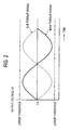
- the main torque signal V tm and the sub torque signal V ts are outputted to respectively have waveforms each of which is inversion of another one with respect to an output voltage of 2.5 V, as shown in FIG. 2, in a state in which no torque is generated.
- the main torque signal V tm and the sub torque signal V ts that the outputted signals V tm and V ts are not inversion each other with respect to 2.5 V, it is determined that a failure of one of the detection coils L1, L2, the resistors R1, R2, the main torque amplifier 11, and the sub torque amplifier 12 is caused.
- an abnormality detection signal V er is outputted from the abnormality detection portion 51.
- the abnormality detection portion 15 detects that all the detection coils L1, L2, the resistors R1, R2, the main torque amplifier 11, and the sub torque amplifier 12 are normal, a signal representing a normal condition is outputted to the control circuit of the power steering apparatus (not shown) . Then, computation of a steering assist command according to the main torque signal V tm , and a steering assist operation are performed.
- an abnormality detection signal V er indicating occurrence of an abnormal condition is outputted to the control circuit of the electric power steering apparatus (not shown). Thus, the mode thereof is changed into a fail safe mode.
- the shortcircuit failure detection portion 16 provided at the side of the control circuit is operated to detect a shortcircuit occurring between the main torque signal line and the sub torque signal line when the test mode is set. A shortcircuit detection process performed by the shortcircuit failure detection portion 16 will be described later in detail.
- the monitoring portion 13 is fundamentally operative to monitor an abnormality in the amplitude of the AC voltage signal V osc supplied to the bridge circuit. Also, the monitoring portion 13 has the self-diagnosis function. A self-diagnosis process by the monitoring portion 13 in a test mode set just after the ignition key is turned to the ON-position (that is, a process of determining whether the monitoring portion 13 normally operates) is described.
- the self-diagnosis process which is performed by the monitoring portion 13 when a test mode is set, is described.
- the test mode is set, that a normal AC voltage V osc is outputted from a power supply for the torque detection portion, and that the reference voltage generation circuit 18 normally operates to output reference voltages V ref1 to V ref3 , which are inputted to each of the comparators CP1 and CP2 (see FIG. 3) of the monitoring portion 13.
- Reasons for inputting a three-level reference voltage, whose value changes stepwise from V ref1 to V ref3 , to the monitoring portion 13 in the test mode are that a failure state is caused in the monitoring portion 13 by intentionally inputting a reference voltage (having an abnormal value) differing from an ordinary reference voltage (having a normal value), and that the main torque signal V tm and the sub torque signal V ts respectively outputted from the main torque amplifier 11 and the sub torque amplifier 12 are compared with each other at the abnormality detection portion 15 to perform the self-diagnosis for detecting an abnormality of the monitoring portion 13.
- a three-level reference voltage whose value sequentially changes stepwise among preliminarily set three different values as time passes, is inputted, as time passes, under the control of the timer 19 from the reference voltage generation circuit 18 provided in the control circuit of the electric power steering apparatus (not shown) to each of the monitoring portion 13, the main torque amplifier 11, and the sub torque amplifier 12.
- a first reference voltage value V ref1 3.3 V (a normal value)
- a second reference voltage value V ref2 5.0 V (an abnormal value)
- a third reference voltage V ref3 0.0 V (a voltage value corresponding to an abnormal value of the reference voltage).
- the following description is made by assuming that the reference voltage has these values.
- the reference voltage having these values is an example of the reference voltage.
- the reference voltage according to the invention is not limited to this example.
- the monitoring portion 13 which determines whether an inputted reference voltage V ref (whose value ranges from V ref1 to V ref3 ) has a normal value or an abnormal value, is connected to the sub torque amplifier 12.
- V ref whose value ranges from V ref1 to V ref3
- the levels of output signals of the comparators CP1 and CP2 of the monitoring portion 13 are 0. Additionally, the transistors TR1 and TR2 are off.
- the abnormality detection portion 15 determines that the monitoring portion 13 is normal. When at least one of the following conditions (1) to (3) is met, and when this state continues for a predetermined time, the abnormality detection portion 15 determines that the monitoring portion 13 is abnormal.
- the abnormality detection portion 15 determines whether the condition (1) is satisfied.
- the abnormality detection portion 15 determines whether each of the main torque signal V tm and the sub torque signal V ts ranges between the upper limit value V thu and the lower limit value V thd of the following criterion value.
- the abnormality detection portion 15 determines that the monitoring portion 13 is normal.
- the abnormality detection portion 15 determines that each of the main torque signal V tm and the sub torque signal V ts is outside the range between the upper limit value V thu of the abnormality criterion value and the lower limit value V thd thereof, that is, within the following range, and where this state continues for 10 ms, the abnormality detection portion 15 also determines that the monitoring portion 13 is abnormal.
- V thu 4.7 ⁇ V tm
- V tm V thd : 0.3
- V thu 4.7 ⁇ V ts
- V c 5 - V tm - V ts ⁇ 0.3
- the abnormality detection portion 15 determines whether the condition (2) is satisfied. When a time period of 45 ms has elapsed since an abnormality detection operation is started, the reference voltage is set at the second reference voltage value V ref2 (V ref2 : 5.0 V (an abnormal value)) in the monitoring portion 13. The abnormality detection portion 15 determines whether the level of the sub torque signal V ts satisfies the following inequality: V ts ⁇ V thd (the lower limit value of the criterion value V thd : 0.3). When it is confirmed that this inequality is satisfied, the abnormality detection portion 15 determines that the monitoring portion 13 is normal.
- the abnormality detection portion 15 determines that the level of the sub torque signal V ts does not meet the above inequality relating to the lower limit V thd of the abnormality criterion value, that is, the level of the sub torque signal V ts meets the following inequality: V ts ⁇ V thd (V thd : 0.3), and where this state continues for 10 ms, the abnormality detection portion 15 also determines that the monitoring portion 13 is abnormal.
- the abnormality detection portion 15 determines whether the condition (3) is satisfied. When a time period of 90 ms has elapsed since an abnormality detection operation is started, the reference voltage is set at the third reference voltage value V ref3 (V ref3 : 3.0 V (an abnormal value)) in the monitoring portion 13. The abnormality detection portion 15 determines whether the level of the sub torque signal V ts satisfies the following inequality: V ts ⁇ V thd (the lower limit value V thd : 0.3). When it is confirmed that this inequality is satisfied, the abnormality detection portion 15 determines that the monitoring portion 13 is normal.
- the abnormality detection portion 15 determines that the level of the sub torque signal V ts does not meet the above inequality relating to the lower limit V thd of the abnormality criterion value, that is, the level of the sub torque signal V ts meets the following inequality: V ts ⁇ V thd (V thd : 0.3), and where this state continues for 10 ms, the abnormality detection portion 15 also determines that the monitoring portion 13 is abnormal.
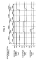
- FIG. 4 is a timing chart illustrating the reference voltage V ref (which has the values V ref1 to V ref3 ), and also illustrating the main torque signal V tm , and the sub torque signal V ts , which are detected by the abnormality detection portion 15, in a self-diagnosis mode of the monitoring portion 13 when the monitoring portion 13 itself is normal.
- FIG. 5 is a timing chart illustrating the reference voltage V ref (which has the values V ref1 to V ref3 ), and also illustrating the main torque signal V tm , and the sub torque signal V ts When the monitoring portion 13 itself is abnormal.
- step 1 the reference voltage is set at the first reference voltage value V ref1 (V ref1 : 3.3 V (a normal value)).
- V ref1 first reference voltage value
- V ref1 3.3 V (a normal value)
- the main torque signal V tm whose level is 2.5 V
- the sub torque signal V ts whose level is also 2.5 V, are detected, so that the above condition (1) is met.
- the abnormality detection portion 15 determines that the monitoring portion 13 is normal.
- step 2 the reference voltage is set at the second reference voltage value V ref2 (V ref2 : 5.0 V (an abnormal value)).
- V ref2 the second reference voltage value
- the main torque signal V tm whose level is 4.7 V
- the sub torque signal V ts whose level is 0.0 V, are detected, so that the above condition (2) is met.
- the abnormality detection portion 15 determines that the monitoring portion 13 is normal.
- 0.0 V is detected as the level of the sub torque signal V ts .
- the monitoring portion 13 is designed so that 0.0 V is detected as the level of the sub torque signal V ts
- the reference voltage V ref has an abnormal value, as described above.
- step 3 the reference voltage is set at the third reference voltage value V ref3 (V ref3 : 0.0 V (an abnormal value)) in the monitoring portion 13.
- V ref3 the third reference voltage value
- the main torque signal V tm whose level is 0.0 V
- the sub torque signal V ts whose level is 0.0 V, are detected, so that the above condition (3) is met.
- the abnormality detection portion 15 determines that the monitoring portion 13 is normal.
- 0.0 V is detected as the level of the sub torque signal V ts .
- the monitoring portion 13 is designed to output a voltage of 0.0 V is outputted as the level of the sub torque signal V ts
- the reference voltage V ref has an abnormal value, as described previously.
- step 1 the reference voltage is set at the first reference voltage value V ref1 (V ref1 : 3.3 V (a normal value)).
- V ref1 first reference voltage value
- V ref1 3.3 V (a normal value)
- the main torque signal V tm whose level is 2.5 V
- the sub torque signal V ts whose level is also 2.5 V, are detected, so that the above condition (1) is met.
- the abnormality detection portion 15 tentatively determines that the monitoring portion 13 is normal.
- step 2 the reference voltage is set at the second reference voltage value V ref2 (V ref2 : 5.0 V (an abnormal value)).
- V ref2 5.0 V (an abnormal value)
- the main torque signal V tm whose level is 3.8 V
- the sub torque signal V ts whose level is also 3. 8 V, are detected.
- the monitoring portion 13 is normal, because the reference voltage V ref has an abnormal value, so that a voltage of 0.0 V is outputted as the voltage represented by the sub torque signal V ts , as described previously.
- the voltages respectively represented by the main torque signal V tm and the sub torque signal V ts are equal to each other. This indicates that the monitoring portion 13 is abnormal.
- the above condition (2) is not satisfied.
- the abnormality detection portion 15 determines that the monitoring portion 13 is abnormal.
- occurrence of a shortcircuit between the main torque signal line and the sub torque signal line is indicated by the fact that the voltages respectively represented by the main torque signal V tm and the sub torque signal V ts are equal to each other.
- step 3 the reference voltage is set at the third reference voltage value V ref3 (V ref3 : 0.0 V (an abnormal value)) in the monitoring portion 13.
- V ref3 the third reference voltage value
- the main torque signal V tm whose level is 0.0 V
- the sub torque signal V ts whose level is 0.0 V
- the abnormality detection portion 15 tentatively determines that the monitoringportion 13 is normal.
- the reference voltage V ref is fixedly set at 3.3 V (a normal value)
- the main torque signal V tm and the sub torque signal V ts both of which has a level of 2.5 V, regardless of whether the monitoring portion 13 is normal or abnormal, even when a shortcircuit occurs between the main torque signal line and the sub torque signal line.
- This voltage value represented by each of the output signals V tm and V ts is equal to that represented by each of the signals V tm and V ts when no shortcircuit occurs between the main torque signal line and the sub torque signal line.
- a shortcircuit occurring between the main torque signal line and the sub torque signal line cannot be detected. This is a reason for changing the reference voltage V ref in three levels.
- the criterion value (or threshold value) according to the invention is not limited thereto.
- the entire time to be elapsed in each of steps 1, 2, and 3 is 45 ms, and that when an abnormal state continues for 10 ms at abnormality determination, the abnormality detection portion 15 determines that the torque sensor is abnormal.
- these are only examples of the elapsed time and the abnormal state continuance time, which are preliminarily set. Further, the elapsed time and the abnormal state continuance time to be preliminarily set according to the invention are not limited thereto.
- the shortcircuit failure detection portion 16 can determine that a shortcircuit occurs between the main torque signal line and the sub torque signal line. When determining that a shortcircuit occurs between the main torque signal line and the sub torque signal line, the shortcircuit failure detection portion 16 outputs a detection signal V sh indicating occurrence of a shortcircuit between the signals lines. When receiving the detection signal V sh representing a shortcircuit failure occurring between the signal lines, the control circuit changes a control mode into a fail safe mode.
- the control circuit informs a driver of occurrence of a shortcircuit failure by an alarm lamp or the like to promote repair of the failure. Also, it is advisable to save a history of occurrence of a shortcircuit failure by, for example, recording the history in a memory and to utilize the history as information for maintenance, and for recurrence prevention and future development at a manufacturing department.
- the torque sensor having the shortcircuit detection portion according to the invention has been described above as a torque sensor applied to an electric power steering apparatus. Needless to say, this torque sensor can be applied to a torque sensor for use in a general industrial machine, in addition to a vehicle steering apparatus.
- the torque sensor according to the invention is adapted to detect torque from impedance changes respectively generated in the two detection coils.
- a failure condition is caused in an abnormality detection portion by intentionally and sequentially changing the reference voltage between the normal reference voltage (corresponding to the normal value) and the other reference voltage (corresponding to an abnormal value), which differs from the normal reference voltage. According to a signal outputted from the abnormality detection portion at that time, a shortcircuit failure occurring between the main torque signal line and the sub torque signal line canbe detected, though such a shortcircuit failure cannot be detected by the conventional failure detection unit.
Landscapes
- Engineering & Computer Science (AREA)
- Chemical & Material Sciences (AREA)
- Combustion & Propulsion (AREA)
- Transportation (AREA)
- Mechanical Engineering (AREA)
- Physics & Mathematics (AREA)
- General Physics & Mathematics (AREA)
- Power Steering Mechanism (AREA)
Abstract
Description
- This invention relates to an electric power steering apparatus and, more particularly, to an electric power steering apparatus enabled to detect a failure of a torque sensor incorporated in an electric power steering apparatus, especially, a failure of a shortcircuit of a pair of detection coils detecting steering torque.
- A non-contact torque sensor is known, having a torque detection portion adapted to convert twist motion of a torsion bar, which is proportional to steering torque, into change in inductance of a pair of detection coils, a bridge circuit configured by a pair of detection coils and a pair of resistors to output a detection signal corresponding to change in the inductance, a main torque amplifier amplifying a main torque signal outputted by the bridge circuit, and a sub torque amplifier amplifying a sub torque signal outputted by the bridge circuit.
- To enhance the fail safe function of the torque sensor, it has been desired to configure the electric power steering apparatus to automatically perform periodical operation tests on the torque sensor at every lapse of a predetermined period, for example, at initial diagnosis of a control unit of the electricpower steering apparatus after an ignition key is turned to an ON-position, or during an operating state.
- The torque sensor has a drawback in that torque cannot accurately be detected, especially, at occurrence of an abnormality, for example, at reduction in the amplitude of an AC voltage signal supplied to the bridge circuit constituted by a pair of detection coils and a pair of resistors in the torque sensor for some cause.
- As a countermeasure against this drawback, it has been proposed a torque detection circuit which is suitable for use in the above torque sensor and which has a monitoring portion enabled to monitor the amplitude of an AC voltage signal to be supplied to the bridge circuit and also enabled to determine whether the torque detection circuit itself normally operates (see
Japanese Patent Unexamined Publication JP-A-2002-48656 - FIG. 6 is a block diagram illustrating the configurations of the conventional
torque detection circuit 100 and a peripheral circuit incorporated in acontrol circuit 200 that controls an electric power steering apparatus (not shown) associated with thetorque detection circuit 100. An AC voltage Vosc is supplied to a bridge circuit constituted by a first arm, which has a detection coil L1 and a resistor R1, and a second arm having a detection coil L2 and a resistor R2. A main torque signal Vtm is obtained by amplifying a differential voltage Vdef and a voltage outputted from the connecting part between the detection coil L2 and the resistor R2 of the second arm through a main torque amplifying circuit. Note that the differential voltage Vdef represents the difference between a voltage outputted from the connecting part between the detection coil L1 and the resistor R1 of the first arm. Additionally, a sub torque signal Vts is obtained by amplifying the differential voltage Vdef through a sub torque amplifying circuit. - The
torque detection circuit 100 is configured so that an abnormality thereof is detected by comparing the detected main torque signal Vtm with the detected sub torque signal Vts at anabnormality detection portion 105, and that when an abnormality is detected, thetorque detection circuit 100 outputs an abnormality detection signal to change a mode of an electric power steering apparatus into a fail safe mode. Additionally, different reference voltages are supplied to amonitoring portion 103 from a reference voltage generation circuit (not shown). Thus, themonitoring portion 103 monitors whether an abnormality of the amplitude of the AC voltage signal Vosc occurs. Also, themonitoring portion 103 has a self-diagnostic mode to determine whether themonitoring portion 103 normally operates (see theJP-A-2002-48656 - In a case where a failure of an electric power steering apparatus occurs, usually, a main body and a control unit of the electric power steering apparatus are replaced at a service station. These collected units causing failures are analyzed at a manufacturing department. Results are used for study on measures to prevent recurrences of the failures and for future development.
- Meanwhile, among various failures, a shortcircuit failure occurring between a main torque signal line and a sub torque signal line of a torque sensor is poor in reproducibility. Thus, even when the collected unit is operated under the same conditions as those under which a failure has occurred, the apparatus often fails to reproduce the failure. Fails being poor in reproducibility are not necessarily the shortcircuit failures occurring between the main torque signal line and the sub torque signal line. Therefore, the causes of the failure should be determined by performing various tests and checks. However, it takes significant cost and time to identify the failure as a shortcircuit failure occurring between the main torque signal line and the sub torque signal line. Accordingly, it has been earnestly desired to easily identify the failure as a shortcircuit failure occurring between torque signal lines.
- Hitherto, in a case where a failure of the torque sensor is detected at initial diagnosis performed by the control unit just after the ignition key is turned to the ON-position, the mode of the apparatus has been changed to the fail safe mode in which a steering assisted by a motor is stopped. However, when the shortcircuit failure occurring between the main torque signal line and the sub torque signal line, neither amain torque signal nor a sub torque signal represents an abnormal value. Thus, in such a case, even when the steering assist is continued by using, for example, a main torque signal, no troubles occur.
- The configuration of the monitoring portion monitors an abnormality in the amplitude of an AC voltage Vosc to be supplied to the torque detection circuit and an operation in the self-diagnosis mode of the monitoring portion have been studied in detail. Consequently, it has been found that a shortcircuit failure occurring between the main torque signal line and the sub torque signal line can be detected.
- An object of the invention is to provide a shortcircuit failure detection device, which detects a shortcircuit failure occurring between a main torque signal line and a sub torque signal line, by enhancing the function of the monitoring portion of the torque detection circuit.
- To solve the above problems, according to the invention, there is provided an electric power steering apparatus, comprising a torque detection unit comprising:
- a torque detection element comprising a pair of detection coils of which impedances change in accordance with torque;
- a torque detection portion comprising a monitoring portion which monitors the torque detection element; and
- a shortcircuit failure detection portion which detects a shortcircuit failure occurring between a main torque signal line and a sub torque signal line of the detection coils, wherein
- the shortcircuit failure detection portion detects the shortcircuit failure occurring between the main torque signal line and the sub torque signal line by comparing a main torque signal and a sub torque signal, which are outputted from the torque detection portion when an abnormal condition is intentionally set in the monitoring portion.
- According to a second aspect of the invention, as set forth in the first aspect of the invention, it is preferable that the torque sensor further comprises a reference voltage generation circuit which outputs a particular reference voltage, which differs from a standard reference voltage, to the monitoring portion and
when a test mode, in which a torque detection circuit is tested, is set, the abnormal condition is intentionally set in the monitoring portion by setting the particular reference voltage therein. - According to a third aspect of the invention, as set forth in the second aspect of the invention, it is preferable that the particular reference voltage, which is set in the monitoring portion when the test mode is set, exceeds the standard reference voltage.
- According to a fourth aspect of the invention, as set forth in the first aspect of the invention, it is preferable that the monitoring portion is configured so that when an abnormal condition is set therein by intentionally setting the particular reference voltage therein, the sub torque signal line is grounded.
- According to a fifth aspect of the invention, as set forth in the first aspect of the invention, it is preferable that the shortcircuit failure detection portion determines that the shortcircuit failure occurring between the main torque signal line and the sub torque signal line occurs in a case where a test mode is set, where an abnormal condition is set in the monitoring portion by setting a particular reference voltage exceeding a standard reference voltage therein, and where a main torque signal voltage and a sub torque signal voltage outputted from the torque detection portion are equal to each other.
- According to a sixth aspect of the invention, as set forth in the first aspect of the invention, it is preferable that when the shortcircuit failure is detected, the torque sensor changes a mode thereof into a fail safe mode.
- According to the invention, the monitoring portion fundamentally monitors the value of an AC voltage supplied to the torque detection portion. However, the monitoring portion has a self-diagnosis function of diagnosing itself. When a reference voltage differing from a standard reference voltage in the monitoring portion, the monitoring portion can detect an abnormality occurring in the monitoring portion itself by comparing a main torque signal and a sub torque signal outputted from the torque detection portion. The invention applies the self-diagnosis function to the detection of a shortcircuit failure occurring between the main torque signal line and the sub torque signal line. That is, the particular reference voltage, which is higher than the standard reference voltage, is set in the monitoring portion to intentionally set an abnormal condition therein. Also, when a main torque signal voltage and a sub torque signal voltage are equal in value to each other in this condition, it is determined that a shortcircuit failure occurring between the main torque signal line and the sub torque signal line occurs.
- Consequently, the apparatus according to the invention can easily detect a shortcircuit failure occurring between the main torque signal line and the sub torque signal line, which cannot be detected by the conventional failure detection means.
-
- FIG. 1 is a block diagram illustrating the configuration of a torque detection portion according to an embodiment of the invention;
- FIG. 2 is a waveform chart illustrating an example of the waveform of each of a main torque signal and a sub torque signal outputted from the torque detection portion;
- FIG. 3 is a block diagram illustrating the configuration of a monitoring part of the torque detection portion;
- FIG. 4 is a timing chart illustrating a reference voltage Vref, a main torque signal Vtm, and a sub torque signal Vts in a self-diagnosis mode of the monitoring part in a case where the monitoring part itself is normal;
- FIG. 5 is a timing chart illustrating a reference voltage Vref, a main torque signal Vtm, and a sub torque signal Vts in the self-diagnosis mode of the monitoring part in a case where the monitoring part itself is abnormal; and
- FIG. 6 is a block diagram illustrating the configuration of a conventional torque sensor.
- Hereinafter, a torque detection portion of a torque sensor according to an embodiment of the invention is described with reference to an example of the application of the torque detection portion to a vehicle electric power steering apparatus.
- FIG. 1 is a circuit block diagram illustrating the configuration of a
torque detection portion 10 according to the present embodiment of the invention and also illustrating the configuration of peripheral circuits of thetorque detection portion 10. The peripheral circuits are provided in acontrol circuit 20 of an electric power steering apparatus (not shown) and include anabnormality detection portion 15, a shortcircuitfailure detection portion 16, a referencevoltage generation circuit 18, and atimer 19. - The
torque detection portion 10 includes a bridge circuit which has a first arm including a detection coil L1 and a resistor R1 and also has a second arm including a detection coil L2 and a resistor R2, and also includes amain torque amplifier 11, asub torque amplifier 12, and amonitoring portion 13. An AC voltage Vosc is supplied from a power supply (not shown) of thecontrol circuit 20 of the electric power steering apparatus to themonitoring portion 13. - A voltage V1 outputted from the connecting part between the detection coil L1 and the resistor R1 of the first arm of the
torque detection portion 10. A voltage V2 outputted from the connecting part between the detection coil L2 and the resistor R2 of the second arm thereof. The voltages V1 and V2 are inputted to themain torque amplifier 11. Then, a voltage Vdef representing the difference between the voltages V1 and V2 inputted to themain torque amplifier 11 is amplified. Subsequently, a signal representing the amplified voltage is outputted therefrom as a main torque signal Vtm. The output voltages V1 and V2 are inputted to thesub torque amplifier 12. Then, a voltage Vdef representing the difference between the voltages V1 and V2 inputted to thesub torque amplifier 12 is amplified. Subsequently, a signal representing the amplified voltage is outputted therefrom as a sub torque signal Vts. - The monitoring
portion 13 is fundamentally operative to monitor an abnormality of the amplitude of the AC voltage signal Vosc supplied to the bridge circuit by comparing the amplitude of the AC voltage signal Vosc with that of a signal representing the reference voltage (see theJP-A-2002-48656 portion 13 has the self-diagnosis function of diagnosing whether the monitoringportion 13 works normally. The invention applies the self-diagnosis function of the monitoringportion 13 to the detection of a shortcircuit failure occurring between the main torque signal line and the sub torque signal. The detection of a shortcircuit failure will be described in detail later. - FIG. 3 is a block diagram illustrating the configuration of the monitoring
portion 13. Hereinafter, the self-diagnosis function of the monitoringportion 13 is described. - The AC voltage Vosc and a reference voltage Vref representing a threshold value exceeding a peak value of the normal AC voltage Vosc are inputted to each of comparators CP1 and CP2. When the peak value of the normal AC voltage is, for example, 4.8 V (at a positive terminal (+)), the reference voltage Vref representing a threshold value exceeding this peak value is set to be 6.2V (Vref = 6.2 (= 5.0 + 1.2)). This is because self-diagnosis is performed by changing a normal threshold value corresponding to the
monitoring portion 13 to intentionally set an abnormal condition in themonitoring portion 13. - According to this setting, the amplitude of the AC voltage signal Vosc inputted to the positive terminal of the comparator CP1 is equal to or less than that of the reference voltage signal Vref. Thus, the level of an output signal of the comparator CP1 is 0, so that a transistor TR1 is brought into an OFF-state. Also, the level of an output signal of the comparator CP2 is 0, so that a transistor TR2 is brought into an OFF-state. Consequently, an output signal of an OR-circuit is on (corresponding to a binary value of "1"), so that the transistor TR is brought into a conduction state. Thus, an output signal of the
sub torque amplifier 12 is grounded, so that a sub torque signal Vts, whose level is 0, is outputted (Vts = 0). This sub torque signal Vts indicates that an abnormality occurs in themonitoring portion 13. Conversely, when a sub torque signal Vts, whose level is not 0, is outputted (Vts # 0), this sub torque signal Vts indicates that the monitoringportion 13 is normal. - In this case, an abnormal condition is intentionally set in the
monitoring portion 13 by changing the threshold value in a test mode to perform the self-diagnosis of the monitoringportion 13. Therefore, according to the fact that a signal (Vts= 0) indicating the occurrence of an abnormality is outputted from the monitoringportion 13, it can be determined that the monitoringportion 13 normally operates. Conversely, when a signal (Vts # 0) indicating that the monitoringportion 13 is normal, it can be determined that an abnormality occurs in themonitoring portion 13. - The
abnormality detection portion 15 provided at the side of the control circuit is configured so that in an ordinary condition, that is, when a test mode for diagnosing the condition of the control circuit of the power steering apparatus, which is described later, is not set, a main torque signal Vtm is compared with a sub torque signal Vts in theabnormality detection portion 15. Theabnormality detection portion 15 detects an abnormality of thetorque detection portion 10 according to a result of the comparison. - That is, when the
torque detection portion 10 is normal, the main torque signal Vtm and the sub torque signal Vts are outputted to respectively have waveforms each of which is inversion of another one with respect to an output voltage of 2.5 V, as shown in FIG. 2, in a state in which no torque is generated. However, when it is found as a result of the comparison between the main torque signal Vtm and the sub torque signal Vts that the outputted signals Vtm and Vts are not inversion each other with respect to 2.5 V, it is determined that a failure of one of the detection coils L1, L2, the resistors R1, R2, themain torque amplifier 11, and thesub torque amplifier 12 is caused. Also, an abnormality detection signal Ver is outputted from the abnormality detection portion 51. - When the
abnormality detection portion 15 detects that all the detection coils L1, L2, the resistors R1, R2, themain torque amplifier 11, and thesub torque amplifier 12 are normal, a signal representing a normal condition is outputted to the control circuit of the power steering apparatus (not shown) . Then, computation of a steering assist command according to the main torque signal Vtm, and a steering assist operation are performed. When theabnormality detection portion 15 detects an abnormality, an abnormality detection signal Ver indicating occurrence of an abnormal condition is outputted to the control circuit of the electric power steering apparatus (not shown). Thus, the mode thereof is changed into a fail safe mode. - The shortcircuit
failure detection portion 16 provided at the side of the control circuit is operated to detect a shortcircuit occurring between the main torque signal line and the sub torque signal line when the test mode is set. A shortcircuit detection process performed by the shortcircuitfailure detection portion 16 will be described later in detail. - As described previously, the monitoring
portion 13 is fundamentally operative to monitor an abnormality in the amplitude of the AC voltage signal Vosc supplied to the bridge circuit. Also, the monitoringportion 13 has the self-diagnosis function. A self-diagnosis process by the monitoringportion 13 in a test mode set just after the ignition key is turned to the ON-position (that is, a process of determining whether the monitoringportion 13 normally operates) is described. - Hereinafter, the self-diagnosis process, which is performed by the monitoring
portion 13 when a test mode is set, is described. First, it is assumed for performing the self-diagnosis process that the test mode is set, that a normal AC voltage Vosc is outputted from a power supply for the torque detection portion, and that the referencevoltage generation circuit 18 normally operates to output reference voltages Vref1 to Vref3, which are inputted to each of the comparators CP1 and CP2 (see FIG. 3) of the monitoringportion 13. - Reasons for inputting a three-level reference voltage, whose value changes stepwise from Vref1 to Vref3, to the
monitoring portion 13 in the test mode are that a failure state is caused in themonitoring portion 13 by intentionally inputting a reference voltage (having an abnormal value) differing from an ordinary reference voltage (having a normal value), and that the main torque signal Vtm and the sub torque signal Vts respectively outputted from themain torque amplifier 11 and thesub torque amplifier 12 are compared with each other at theabnormality detection portion 15 to perform the self-diagnosis for detecting an abnormality of the monitoringportion 13. - When the test mode is set, a three-level reference voltage, whose value sequentially changes stepwise among preliminarily set three different values as time passes, is inputted, as time passes, under the control of the
timer 19 from the referencevoltage generation circuit 18 provided in the control circuit of the electric power steering apparatus (not shown) to each of the monitoringportion 13, themain torque amplifier 11, and thesub torque amplifier 12. - The value of the three-level reference voltage Vref outputted from the reference
voltage generation circuit 18 changes among the following three values. That is, for an example, a first reference voltage value Vref1 = 3.3 V (a normal value), a second reference voltage value Vref2 = 5.0 V (an abnormal value), and a third reference voltage Vref3 = 0.0 V (a voltage value corresponding to an abnormal value of the reference voltage). The following description is made by assuming that the reference voltage has these values. Incidentally, the reference voltage having these values is an example of the reference voltage. The reference voltage according to the invention is not limited to this example. - The monitoring
portion 13, which determines whether an inputted reference voltage Vref (whose value ranges from Vref1 to Vref3) has a normal value or an abnormal value, is connected to thesub torque amplifier 12. When the value of the reference voltage Vref (whose value ranges from Vref1 to Vref3) has an abnormal value (for example, Vref2 = 5.0 V), the level of the sub torque signal Vts is 0 (Vts = 0). As is apparent from the description of the monitoringportion 13, which has been made with reference to FIG. 3, the levels of output signals of the comparators CP1 and CP2 of the monitoringportion 13 are 0. Additionally, the transistors TR1 and TR2 are off. Thus, an output signal of the OR-circuit is on (corresponding to a binary value of "1"), so that the transistor TR is brought into a conduction state. Consequently, an output signal of thesub torque amplifier 12 is grounded, so that the level of the sub torque signal Vts is forcibly set to be 0 (Vts = 0). - When all the following conditions (1) to (3) are met, the
abnormality detection portion 15 determines that the monitoringportion 13 is normal. When at least one of the following conditions (1) to (3) is met, and when this state continues for a predetermined time, theabnormality detection portion 15 determines that the monitoringportion 13 is abnormal. -
- (1) In a case where the reference voltage is set at the first reference voltage value Vref1 in the
monitoring portion 13, the level of each of the main torque signal and the sub torque signal inputted to theabnormality detection portion 15 ranges between the upper limit value Vthu and the lower limit value Vthd of preliminarily set criterion values (or threshold values). Also, the absolute value of a value obtained by subtracting the difference in level between the main torque signal and the sub torque signal from a predetermined value Vc is less than the lower limit value Vthd of the preliminarily set criterion reference value. - (2) In a case where the reference voltage is set at the second reference voltage value Vref2 in the
monitoring portion 13, the level of the sub torque signal inputted to theabnormality detection portion 15 is less than the lower limit value Vthd of the preliminarily set criterion reference value. - (3) In a case where the reference voltage is set at the third reference voltage value Vref3 in the
monitoring portion 13, the level of the sub torque signal inputted to theabnormality detection portion 15 is less than the lower limit value Vthd of the preliminarily set criterion reference value. - In the following description, it is assumed that the upper limit value Vthu of the abnormality criterion value (or threshold value) is set at 4.7 V (Vthu = 4.7), that the lower limit value Vthd thereof is set at 0 .3V (Vthu= 0.3), and that the predetermined value Vc is set at 5 V (Vc = 5).
- The
abnormality detection portion 15 determines whether the condition (1) is satisfied. An AC voltage level Vosc is set at 9 V (Vosc = 9 V) as a power supply voltage for thetorque detection portion 10. The reference voltage having the first reference voltage level Vref1 (Vref1 = 3.3 V (a normal value)) is outputted from the referencevoltage generation circuit 18 and is set in themonitoring portion 13. Theabnormality detection portion 15 determines whether each of the main torque signal Vtm and the sub torque signal Vts ranges between the upper limit value Vthu and the lower limit value Vthd of the following criterion value. -


- When a result of the determination made by the
abnormality detection portion 15 reveals that each of the main torque signal Vtm and the sub torque signal Vts is within the above range from the criterion value, theabnormality detection portion 15 determines that the monitoringportion 13 is normal. - When the
abnormality detection portion 15 determines that each of the main torque signal Vtm and the sub torque signal Vts is outside the range between the upper limit value Vthu of the abnormality criterion value and the lower limit value Vthd thereof, that is, within the following range, and where this state continues for 10 ms, theabnormality detection portion 15 also determines that the monitoringportion 13 is abnormal. -


- The
abnormality detection portion 15 determines whether the condition (2) is satisfied. When a time period of 45 ms has elapsed since an abnormality detection operation is started, the reference voltage is set at the second reference voltage value Vref2 (Vref2: 5.0 V (an abnormal value)) in themonitoring portion 13. Theabnormality detection portion 15 determines whether the level of the sub torque signal Vts satisfies the following inequality: Vts < Vthd (the lower limit value of the criterion value Vthd: 0.3). When it is confirmed that this inequality is satisfied, theabnormality detection portion 15 determines that the monitoringportion 13 is normal. - When the
abnormality detection portion 15 determines that the level of the sub torque signal Vts does not meet the above inequality relating to the lower limit Vthd of the abnormality criterion value, that is, the level of the sub torque signal Vts meets the following inequality: Vts ≥ Vthd (Vthd: 0.3), and where this state continues for 10 ms, theabnormality detection portion 15 also determines that the monitoringportion 13 is abnormal. - The
abnormality detection portion 15 determines whether the condition (3) is satisfied. When a time period of 90 ms has elapsed since an abnormality detection operation is started, the reference voltage is set at the third reference voltage value Vref3 (Vref3: 3.0 V (an abnormal value)) in themonitoring portion 13. Theabnormality detection portion 15 determines whether the level of the sub torque signal Vts satisfies the following inequality: Vts < Vthd (the lower limit value Vthd: 0.3). When it is confirmed that this inequality is satisfied, theabnormality detection portion 15 determines that the monitoringportion 13 is normal. - When the
abnormality detection portion 15 determines that the level of the sub torque signal Vts does not meet the above inequality relating to the lower limit Vthd of the abnormality criterion value, that is, the level of the sub torque signal Vts meets the following inequality: Vts ≥ Vthd (Vthd: 0.3), and where this state continues for 10 ms, theabnormality detection portion 15 also determines that the monitoringportion 13 is abnormal. - When a time period of 135 ms has elapsed since an abnormality detection operation is started, the process returns to step 1.
- FIG. 4 is a timing chart illustrating the reference voltage Vref (which has the values Vref1 to Vref3), and also illustrating the main torque signal Vtm, and the sub torque signal Vts, which are detected by the
abnormality detection portion 15, in a self-diagnosis mode of the monitoringportion 13 when the monitoringportion 13 itself is normal. FIG. 5 is a timing chart illustrating the reference voltage Vref (which has the values Vref1 to Vref3), and also illustrating the main torque signal Vtm, and the sub torque signal Vts When the monitoringportion 13 itself is abnormal. - First, the main torque signal Vtm, and the sub torque signal Vts, which are detected by the
abnormality detection portion 15, When the monitoring portion itself 13 is normal, are described below by referring to FIG. 4. - In
step 1, the reference voltage is set at the first reference voltage value Vref1 (Vref1: 3.3 V (a normal value)). The main torque signal Vtm, whose level is 2.5 V, and the sub torque signal Vts, whose level is also 2.5 V, are detected, so that the above condition (1) is met. Thus, theabnormality detection portion 15 determines that the monitoringportion 13 is normal. - This process proceeds to step 2 after a time period of 45 ms has elapsed since the abnormality detection operation is commenced. In step 2, the reference voltage is set at the second reference voltage value Vref2 (Vref2: 5.0 V (an abnormal value)). The main torque signal Vtm, whose level is 4.7 V, and the sub torque signal Vts, whose level is 0.0 V, are detected, so that the above condition (2) is met. Thus, the
abnormality detection portion 15 determines that the monitoringportion 13 is normal. - In this step, 0.0 V is detected as the level of the sub torque signal Vts. This is because the
monitoring portion 13 is designed so that 0.0 V is detected as the level of the sub torque signal Vts When the reference voltage Vref has an abnormal value, as described above. - The process proceeds to step 3 after a time period of 90 ms has elapsed since the abnormality detection operation is commenced. In step 3, the reference voltage is set at the third reference voltage value Vref3 (Vref3: 0.0 V (an abnormal value)) in the
monitoring portion 13. The main torque signal Vtm, whose level is 0.0 V, and the sub torque signal Vts, whose level is 0.0 V, are detected, so that the above condition (3) is met. Thus, theabnormality detection portion 15 determines that the monitoringportion 13 is normal. - In this step, 0.0 V is detected as the level of the sub torque signal Vts. This is because the
monitoring portion 13 is designed to output a voltage of 0.0 V is outputted as the level of the sub torque signal Vts When the reference voltage Vref has an abnormal value, as described previously. - Next, the main torque signal Vtm, and the sub torque signal Vts, which are detected by the
abnormality detection portion 15, When the monitoring portion itself 13 is abnormal, are described below by referring to FIG. 5. - In
step 1, the reference voltage is set at the first reference voltage value Vref1 (Vref1: 3.3 V (a normal value)). The main torque signal Vtm, whose level is 2.5 V, and the sub torque signal Vts, whose level is also 2.5 V, are detected, so that the above condition (1) is met. Thus, theabnormality detection portion 15 tentatively determines that the monitoringportion 13 is normal. - This process proceeds to step 2 after a time period of 45 ms has elapsed since the abnormality detection operation is commenced. In step 2, the reference voltage is set at the second reference voltage value Vref2 (Vref2: 5.0 V (an abnormal value)). The main torque signal Vtm, whose level is 3.8 V, and the sub torque signal Vts, whose level is also 3. 8 V, are detected. When the monitoring
portion 13 is normal, because the reference voltage Vref has an abnormal value, so that a voltage of 0.0 V is outputted as the voltage represented by the sub torque signal Vts, as described previously. However, the voltages respectively represented by the main torque signal Vtm and the sub torque signal Vts are equal to each other. This indicates that the monitoringportion 13 is abnormal. At that time, the above condition (2) is not satisfied. Thus, theabnormality detection portion 15 determines that the monitoringportion 13 is abnormal. - Incidentally, occurrence of a shortcircuit between the main torque signal line and the sub torque signal line is indicated by the fact that the voltages respectively represented by the main torque signal Vtm and the sub torque signal Vts are equal to each other.
- This process proceeds to step 3 after a time period of 90 ms has elapsed since the abnormality detection operation is commenced. In step 3, the reference voltage is set at the third reference voltage value Vref3 (Vref3: 0.0 V (an abnormal value)) in the
monitoring portion 13. The main torque signal Vtm, whose level is 0.0 V, and the sub torque signal Vts, whose level is 0.0 V, are detected, so that the above condition (3) is satisfied. Thus, theabnormality detection portion 15 tentatively determines that themonitoringportion 13 is normal. - When the reference voltage Vref is fixedly set at 3.3 V (a normal value), the main torque signal Vtm and the sub torque signal Vts, both of which has a level of 2.5 V, regardless of whether the monitoring
portion 13 is normal or abnormal, even when a shortcircuit occurs between the main torque signal line and the sub torque signal line. This voltage value represented by each of the output signals Vtm and Vts is equal to that represented by each of the signals Vtm and Vts when no shortcircuit occurs between the main torque signal line and the sub torque signal line. Thus, a shortcircuit occurring between the main torque signal line and the sub torque signal line cannot be detected. This is a reason for changing the reference voltage Vref in three levels. - Incidentally, the upper limit value Vthu (Vthu = 4.7) and the lower limit value Vthd (Vthd = 0.3) of the criterion value (or threshold value) for the main torque signal Vtm and the sub torque signal Vts and the predetermined value Vc (Vc = 5), which are employed in the self-diagnosis process that has been described in the foregoing description and that is performed by the monitoring
portion 13, are only an example of the criterion value (or threshold value). The criterion value (or threshold value) according to the invention is not limited thereto. It has been described in the foregoing description that the entire time to be elapsed in each ofsteps 1, 2, and 3 is 45 ms, and that when an abnormal state continues for 10 ms at abnormality determination, theabnormality detection portion 15 determines that the torque sensor is abnormal. However, these are only examples of the elapsed time and the abnormal state continuance time, which are preliminarily set. Further, the elapsed time and the abnormal state continuance time to be preliminarily set according to the invention are not limited thereto. - Next, a process of detecting a shortcircuit occurring between the main torque signal line and the sub torque signal line, which is performed by the shortcircuit
failure detection portion 16, is described below. - A shortcircuit detection process is performed in the test mode immediately after the ignition key is turned to the ON-position. Similarly to the self-diagnosis process performed by the monitoring
portion 13 itself, which has been described previously, the shortcircuit detection process is performed by setting the reference voltage at the value Vref2 (= 5.0 V (an abnormal value)) in themonitoring portion 13. - The shortcircuit
failure detection portion 16 compares the main torque signal Vtm outputted from themain torque amplifier 11 with the sub torque signal Vts outputted from thesub torque amplifier 12. That is, when the reference voltage having the second reference voltage value Vref2 (= 5.0 V (an abnormal value)) to themonitoring portion 13, a signal representing a voltage, whose value Vtm is equal to or less than 4 .7 V, is outputted as the main torque signal when the monitoringportion 13 is normal. However, the reference voltage value Vref2 is an abnormal value. Thus, a sub torque signal Vts, whose value is forcibly set to be 0, is outputted from thesub torque amplifier 16. Consequently, the voltage levels respectively represented by the main torque signal Vtm and the sub torque signal Vts inputtedto theshortcircuit failure detectionportion 16 should differ from each other. - Thus, when the voltage levels respectively represented by the main torque signal Vtm and the sub torque signal Vts inputted to the shortcircuit
failure detection portion 16 are equal to each other (Vtm= Vts), the shortcircuitfailure detection portion 16 can determine that a shortcircuit occurs between the main torque signal line and the sub torque signal line. When determining that a shortcircuit occurs between the main torque signal line and the sub torque signal line, the shortcircuitfailure detection portion 16 outputs a detection signal Vsh indicating occurrence of a shortcircuit between the signals lines. When receiving the detection signal Vsh representing a shortcircuit failure occurring between the signal lines, the control circuit changes a control mode into a fail safe mode. - Also, it is advisable that when receiving the detection signal Vsh representing a shortcircuit failure occurringbetween the signal lines, the control circuit informs a driver of occurrence of a shortcircuit failure by an alarm lamp or the like to promote repair of the failure. Also, it is advisable to save a history of occurrence of a shortcircuit failure by, for example, recording the history in a memory and to utilize the history as information for maintenance, and for recurrence prevention and future development at a manufacturing department.
- Also, When a shortcircuit failure occurrences, it is advisable to continue to perform a steering assist control operation based on a main torque signal to facilitate conveyance of a vehicle to a service station. In this case, it is advisable to change the control mode into a fail safe mode, in which a steering assist force is halved, so as to make a driver to notice the shortcircuit failure and as to promote the driver to repair.
- That is, when a failure of the torque sensor is detected at initial diagnosis performed by the control unit just after the ignition key is turned to the ON-position, it is advisable to inform a driver of the abnormality of the torque sensor by an alarm lamp or the like, and to determine whether the failure is a shortcircuit failure occurring between signal lines. Additionally, when the shortcircuit failure is occurredbetween the signal lines, it is advisable to change the control mode into the fail safe mode, in which a steering assist force is halved, and to continue to perform a steering assist control operation according to a main torque signal. Because the steering assist force is halved, a handle operation is less responsive than usual. However, the vehicle can be conveyed to the service station. In this case, it is advisable that whether the main torque signal used for steering assist represents an appropriate value is determined according to whether a voltage level represented by the main torque signal is within a range between the upper limit value and the lower limit value of the threshold value.
- As is apparent from the foregoing description, the shortcircuit
failure detection portion 16 performs a shortcircuit detection process that is similar to the self-diagnosis process performed by themonitoring part 13. Therefore, the shortcircuit detection process performed by the shortcircuitfailure detection portion 16 described in the foregoing description can be performed by themonitoring part 13. In this case, it is advisable to provide a shortcircuit detection mode as one of test modes, and to set, when themonitoring part 13 performs the shortcircuit detection process, the reference voltage Vref2 (= 5.0V (corresponding to an abnormality value)) in themonitoring part 13. - The torque sensor having the shortcircuit detection portion according to the invention has been described above as a torque sensor applied to an electric power steering apparatus. Needless to say, this torque sensor can be applied to a torque sensor for use in a general industrial machine, in addition to a vehicle steering apparatus.
- The torque sensor according to the invention is adapted to detect torque from impedance changes respectively generated in the two detection coils. A failure condition is caused in an abnormality detection portion by intentionally and sequentially changing the reference voltage between the normal reference voltage (corresponding to the normal value) and the other reference voltage (corresponding to an abnormal value), which differs from the normal reference voltage. According to a signal outputted from the abnormality detection portion at that time, a shortcircuit failure occurring between the main torque signal line and the sub torque signal line canbe detected, though such a shortcircuit failure cannot be detected by the conventional failure detection unit.
- While the invention has been described in connection with the exemplary embodiments, it will be obvious to those skilled in the art that various changes and modification may be made therein without departing from the present invention, and it is aimed, therefore, to cover in the appended claim all such changes and modifications as fall within the true spirit and scope of the present invention.
Claims (6)
- An electric power steering apparatus, comprising a torque detection unit comprising:a torque detection element comprising a pair of detection coils of which impedances change in accordance with torque;a torque detection portion comprising a monitoring portion which monitors the torque detection element; anda shortcircuit failure detection portion which detects a shortcircuit failure occurring between a main torque signal line and a sub torque signal line of the detection coils, whereinthe shortcircuit failure detection portion detects the shortcircuit failure occurring between the main torque signal line and the sub torque signal line by comparing a main torque signal and a sub torque signal, which are outputted from the torque detection portion when an abnormal condition is intentionally set in the monitoring portion.
- The electric power steering apparatus according to claim 1, wherein the torque sensor further comprises a reference voltage generation circuit which outputs a particular reference voltage, which differs from a standard reference voltage, to the monitoring portion and
when a test mode, in which a torque detection circuit is tested, is set, the abnormal condition is intentionally set in the monitoring portion by setting the particular reference voltage therein. - The electric power steering apparatus according to claim 2, wherein the particular reference voltage, which is set in the monitoring portion when the test mode is set, exceeds the standard reference voltage.
- The electric power steering apparatus according to claim 1, wherein the monitoring portion is configured so that when an abnormal condition is set therein by intentionally setting the particular reference voltage therein, the sub torque signal line is grounded.
- The electric power steering apparatus according to claim 1, wherein the shortcircuit failure detection portion determines that the shortcircuit failure occurring between the main torque signal line and the sub torque signal line occurs in a case where a test mode is set, where an abnormal condition is set in the monitoring portion by setting a particular reference voltage exceeding a standard reference voltage therein, and where a main torque signal voltage and a sub torque signal voltage outputted from the torque detection portion are equal to each other.
- The electric power steering apparatus according to claim 1, wherein when the shortcircuit failure is detected, the torque sensor changes a mode thereof into a fail safe mode.
Applications Claiming Priority (1)
| Application Number | Priority Date | Filing Date | Title |
|---|---|---|---|
| JP2006045573A JP2007225388A (en) | 2006-02-22 | 2006-02-22 | Electric power steering device |
Publications (1)
| Publication Number | Publication Date |
|---|---|
| EP1826097A1 true EP1826097A1 (en) | 2007-08-29 |
Family
ID=38050985
Family Applications (1)
| Application Number | Title | Priority Date | Filing Date |
|---|---|---|---|
| EP07003590A Withdrawn EP1826097A1 (en) | 2006-02-22 | 2007-02-21 | Electric power steering apparatus |
Country Status (3)
| Country | Link |
|---|---|
| US (1) | US7474070B2 (en) |
| EP (1) | EP1826097A1 (en) |
| JP (1) | JP2007225388A (en) |
Cited By (4)
| Publication number | Priority date | Publication date | Assignee | Title |
|---|---|---|---|---|
| EP2559985A4 (en) * | 2011-06-21 | 2014-07-09 | Nsk Ltd | Abnormality diagnosis method for torque detection device, and electric power steering device |
| EP2835624A3 (en) * | 2013-08-08 | 2015-07-01 | Jtekt Corporation | Sensor device, motor control device, and electric power steering apparatus |
| EP2907727A4 (en) * | 2012-10-10 | 2016-06-15 | Nsk Ltd | Device for detecting physical quantities and electromotive power steering device using same |
| EP2913648A4 (en) * | 2012-10-23 | 2016-12-07 | Nsk Ltd | TORQUE DETECTION DEVICE, POWER SUPPLY DEVICE, AND VEHICLE |
Families Citing this family (8)
| Publication number | Priority date | Publication date | Assignee | Title |
|---|---|---|---|---|
| JP4610300B2 (en) * | 2004-11-02 | 2011-01-12 | 富士通テン株式会社 | VEHICLE CONTROL DEVICE AND VEHICLE CONTROL METHOD |
| JP5018577B2 (en) * | 2008-03-17 | 2012-09-05 | 日本精工株式会社 | Electric power steering device |
| DE102009045351A1 (en) * | 2009-10-06 | 2011-04-14 | Robert Bosch Gmbh | Method for operating a drive unit and drive unit |
| US8719383B2 (en) * | 2011-07-05 | 2014-05-06 | At&T Intellectual Property I, L.P. | Enhanced method to deliver/pre-load corrective how-to information to an end user |
| DE102012202642A1 (en) * | 2012-02-21 | 2013-08-22 | Siemens Aktiengesellschaft | Electric switch |
| JP6679861B2 (en) * | 2015-09-15 | 2020-04-15 | 株式会社デンソー | Sensor device and electric power steering device using the same |
| JP7414514B2 (en) * | 2019-12-23 | 2024-01-16 | ファナック株式会社 | Monitoring device, motor drive device and monitoring method |
| CN113562065B (en) * | 2021-07-15 | 2022-06-03 | 东风汽车集团股份有限公司 | Control method and device for preventing data abnormality of electric power steering controller |
Citations (6)
| Publication number | Priority date | Publication date | Assignee | Title |
|---|---|---|---|---|
| US4956590A (en) * | 1988-10-06 | 1990-09-11 | Techco Corporation | Vehicular power steering system |
| EP0984256A2 (en) * | 1998-09-01 | 2000-03-08 | Toyoda Koki Kabushiki Kaisha | Torque sensor |
| EP1095841A2 (en) * | 1999-10-29 | 2001-05-02 | Toyota Jidosha Kabushiki Kaisha | Vehicular electric power steering device |
| US6456090B1 (en) * | 1999-09-27 | 2002-09-24 | Nsk Ltd. | Torque sensor |
| EP1426749A1 (en) * | 2002-12-06 | 2004-06-09 | HONDA MOTOR CO., Ltd. | Torque sensor |
| EP1595767A2 (en) * | 2004-05-13 | 2005-11-16 | Nsk Ltd | Power steering control device for monitoring reference voltage |
Family Cites Families (17)
| Publication number | Priority date | Publication date | Assignee | Title |
|---|---|---|---|---|
| JPS63141875A (en) * | 1986-12-02 | 1988-06-14 | Mitsubishi Electric Corp | Motor driven type power steering device |
| JP2602963B2 (en) * | 1989-10-03 | 1997-04-23 | 三菱電機株式会社 | Motor-driven power steering device |
| JPH08132992A (en) * | 1994-11-10 | 1996-05-28 | Mitsubishi Electric Corp | In-vehicle control device |
| GB9604431D0 (en) * | 1996-03-01 | 1996-05-01 | Lucas Ind Plc | Circuit for testing an electrical actuator drive stage |
| JP3518944B2 (en) * | 1996-04-11 | 2004-04-12 | 三菱電機株式会社 | Motor drive |
| JP3274377B2 (en) * | 1996-12-25 | 2002-04-15 | 三菱電機株式会社 | Load short-circuit fault detection method and device, and electric power steering device |
| DE69737146T2 (en) * | 1997-06-20 | 2007-10-04 | Mitsubishi Denki K.K. | MOTORIZED POWER STEERING |
| JP3696384B2 (en) * | 1997-09-16 | 2005-09-14 | 本田技研工業株式会社 | Electric motor drive |
| JP3486749B2 (en) * | 2000-04-05 | 2004-01-13 | 本田技研工業株式会社 | Electric power steering device |
| JP3664055B2 (en) | 2000-08-04 | 2005-06-22 | 日本精工株式会社 | Torque sensor control device |
| JP4461615B2 (en) * | 2000-12-13 | 2010-05-12 | 株式会社デンソー | Control device for electric power steering mechanism |
| US6594125B2 (en) * | 2001-03-29 | 2003-07-15 | Siemens Energy & Automation, Inc. | Vehicle electrical system arc detection apparatus and method |
| JP4089367B2 (en) * | 2002-09-17 | 2008-05-28 | 株式会社ジェイテクト | Electric power steering device |
| JP4289458B2 (en) * | 2004-09-07 | 2009-07-01 | 三菱電機株式会社 | Electric power steering control device |
| JP3931184B2 (en) * | 2004-09-10 | 2007-06-13 | 三菱電機株式会社 | Motor control device |
| KR100572397B1 (en) * | 2004-11-16 | 2006-04-18 | 현대모비스 주식회사 | Fault diagnosis system of torque sensor for steering device of vehicle and its method |
| JP2006273155A (en) * | 2005-03-29 | 2006-10-12 | Showa Corp | Electric power steering device |
-
2006
- 2006-02-22 JP JP2006045573A patent/JP2007225388A/en active Pending
-
2007
- 2007-02-21 EP EP07003590A patent/EP1826097A1/en not_active Withdrawn
- 2007-02-22 US US11/709,024 patent/US7474070B2/en not_active Expired - Fee Related
Patent Citations (6)
| Publication number | Priority date | Publication date | Assignee | Title |
|---|---|---|---|---|
| US4956590A (en) * | 1988-10-06 | 1990-09-11 | Techco Corporation | Vehicular power steering system |
| EP0984256A2 (en) * | 1998-09-01 | 2000-03-08 | Toyoda Koki Kabushiki Kaisha | Torque sensor |
| US6456090B1 (en) * | 1999-09-27 | 2002-09-24 | Nsk Ltd. | Torque sensor |
| EP1095841A2 (en) * | 1999-10-29 | 2001-05-02 | Toyota Jidosha Kabushiki Kaisha | Vehicular electric power steering device |
| EP1426749A1 (en) * | 2002-12-06 | 2004-06-09 | HONDA MOTOR CO., Ltd. | Torque sensor |
| EP1595767A2 (en) * | 2004-05-13 | 2005-11-16 | Nsk Ltd | Power steering control device for monitoring reference voltage |
Cited By (8)
| Publication number | Priority date | Publication date | Assignee | Title |
|---|---|---|---|---|
| EP2559985A4 (en) * | 2011-06-21 | 2014-07-09 | Nsk Ltd | Abnormality diagnosis method for torque detection device, and electric power steering device |
| US9248853B2 (en) | 2011-06-21 | 2016-02-02 | Nsk, Ltd. | Abnormality diagnosing method for torque detecting device and electric power steering device |
| US9254863B2 (en) | 2011-06-21 | 2016-02-09 | Nsk Ltd. | Torque detecting device and electric power steering device |
| EP2907727A4 (en) * | 2012-10-10 | 2016-06-15 | Nsk Ltd | Device for detecting physical quantities and electromotive power steering device using same |
| US9573619B2 (en) | 2012-10-10 | 2017-02-21 | Nsk Ltd. | Physical quantity detecting device and electric power steering apparatus using same |
| EP2913648A4 (en) * | 2012-10-23 | 2016-12-07 | Nsk Ltd | TORQUE DETECTION DEVICE, POWER SUPPLY DEVICE, AND VEHICLE |
| EP2835624A3 (en) * | 2013-08-08 | 2015-07-01 | Jtekt Corporation | Sensor device, motor control device, and electric power steering apparatus |
| US9772249B2 (en) | 2013-08-08 | 2017-09-26 | Jtekt Corporation | Sensor device, motor control device, and electric power steering apparatus |
Also Published As
| Publication number | Publication date |
|---|---|
| JP2007225388A (en) | 2007-09-06 |
| US20070205734A1 (en) | 2007-09-06 |
| US7474070B2 (en) | 2009-01-06 |
Similar Documents
| Publication | Publication Date | Title |
|---|---|---|
| US7474070B2 (en) | Electric power steering apparatus | |
| US6970807B2 (en) | Diagnostic system and method for electric leak detecting device | |
| US7994799B2 (en) | Insulation resistance detection system, insulation resistance detection apparatus and insulation resistance detection method | |
| US7292042B2 (en) | Ground fault detector for vehicle | |
| US7208955B2 (en) | Power relay or switch contact tester | |
| KR101291895B1 (en) | Electric leakage sensing apparatus | |
| CN105899419B (en) | Midway fault diagnosis system and electric power steering device installed with the midway fault diagnosis system | |
| EP1930737A1 (en) | Insulating resistance detection apparatus | |
| CN110907813A (en) | Diagnosis method for relay in battery management system | |
| JP2008029126A (en) | Booster circuit, motor drive circuit, and electric power steering control device | |
| WO2021106284A1 (en) | Earth leakage detection device and vehicle power supply system | |
| JP2007242247A (en) | Control device for vehicle power supply system | |
| JP3990669B2 (en) | Load fault diagnosis method and apparatus, and load fault processing method and apparatus | |
| CN104483588A (en) | Electrical failure diagnosis method and device for relay control terminal | |
| JP2001304871A (en) | Angular velocity sensor abnormality diagnosis device | |
| CN116698165A (en) | Liquid level sensor and automobile | |
| US7233151B2 (en) | Apparatus and method for diagnosing failure of fuel level sensors | |
| KR101273214B1 (en) | Simulator for car with self diagnosis function and diagnosis method using the same | |
| KR100230014B1 (en) | Device for detecting abnormal condition of automobile-electric circuit | |
| KR200213647Y1 (en) | On-Line Defect Distinction Apparatus of Inverter Union Sensor | |
| JPH1073627A (en) | Self-diagnostic device for ic testing apparatus | |
| JP5014606B2 (en) | Actuator drive circuit | |
| KR100494780B1 (en) | Apparatus for warning abnormal state by smell sensing of engine test system | |
| KR100197107B1 (en) | Self-diagnostic fault preventing method of outputing actuator | |
| KR0136225B1 (en) | Fault diagnosis device and diagnostic method of construction equipment controller |
Legal Events
| Date | Code | Title | Description |
|---|---|---|---|
| PUAI | Public reference made under article 153(3) epc to a published international application that has entered the european phase |
Free format text: ORIGINAL CODE: 0009012 |
|
| AK | Designated contracting states |
Kind code of ref document: A1 Designated state(s): AT BE BG CH CY CZ DE DK EE ES FI FR GB GR HU IE IS IT LI LT LU LV MC NL PL PT RO SE SI SK TR |
|
| AX | Request for extension of the european patent |
Extension state: AL BA HR MK YU |
|
| 17P | Request for examination filed |
Effective date: 20071031 |
|
| AKX | Designation fees paid |
Designated state(s): DE FR |
|
| 17Q | First examination report despatched |
Effective date: 20080523 |
|
| GRAP | Despatch of communication of intention to grant a patent |
Free format text: ORIGINAL CODE: EPIDOSNIGR1 |
|
| STAA | Information on the status of an ep patent application or granted ep patent |
Free format text: STATUS: THE APPLICATION IS DEEMED TO BE WITHDRAWN |
|
| 18D | Application deemed to be withdrawn |
Effective date: 20091007 |