EP1825835A2 - Système de collecte d'urine avec port de prélèvement sans aiguille - Google Patents
Système de collecte d'urine avec port de prélèvement sans aiguille Download PDFInfo
- Publication number
- EP1825835A2 EP1825835A2 EP07250764A EP07250764A EP1825835A2 EP 1825835 A2 EP1825835 A2 EP 1825835A2 EP 07250764 A EP07250764 A EP 07250764A EP 07250764 A EP07250764 A EP 07250764A EP 1825835 A2 EP1825835 A2 EP 1825835A2
- Authority
- EP
- European Patent Office
- Prior art keywords
- collection bag
- fluid
- sampling port
- collection system
- drain tube
- Prior art date
- Legal status (The legal status is an assumption and is not a legal conclusion. Google has not performed a legal analysis and makes no representation as to the accuracy of the status listed.)
- Granted
Links
Images


Classifications
-
- A—HUMAN NECESSITIES
- A61—MEDICAL OR VETERINARY SCIENCE; HYGIENE
- A61F—FILTERS IMPLANTABLE INTO BLOOD VESSELS; PROSTHESES; DEVICES PROVIDING PATENCY TO, OR PREVENTING COLLAPSING OF, TUBULAR STRUCTURES OF THE BODY, e.g. STENTS; ORTHOPAEDIC, NURSING OR CONTRACEPTIVE DEVICES; FOMENTATION; TREATMENT OR PROTECTION OF EYES OR EARS; BANDAGES, DRESSINGS OR ABSORBENT PADS; FIRST-AID KITS
- A61F5/00—Orthopaedic methods or devices for non-surgical treatment of bones or joints; Nursing devices; Anti-rape devices
- A61F5/44—Devices worn by the patient for reception of urine, faeces, catamenial or other discharge; Portable urination aids; Colostomy devices
- A61F5/4404—Details or parts
-
- A—HUMAN NECESSITIES
- A61—MEDICAL OR VETERINARY SCIENCE; HYGIENE
- A61G—TRANSPORT, PERSONAL CONVEYANCES, OR ACCOMMODATION SPECIALLY ADAPTED FOR PATIENTS OR DISABLED PERSONS; OPERATING TABLES OR CHAIRS; CHAIRS FOR DENTISTRY; FUNERAL DEVICES
- A61G7/00—Beds specially adapted for nursing; Devices for lifting patients or disabled persons
- A61G7/05—Parts, details or accessories of beds
- A61G7/0503—Holders, support devices for receptacles, e.g. for drainage or urine bags
Definitions
- the present disclosure relates generally to fluid collection systems. More specifically, the present disclosure relates to fluid collection systems including improved venting structure and means for obtaining a fresh sample of fluid from the system without contaminating fluid within the system or risking injury to medical personnel.
- Urine collection systems for collecting urine from a catheterized patient are well known in the art. Such systems typically include a drain tube having a first end connected to a urinary catheter of a catheterized patient and a second end connected to a urine collection bag.
- the urine collection bag includes an outlet port for draining fluid from the bag.
- samples have been extracted using syringes or hypodermic needles which were inserted through walls of the drain tubing. Samples have also been obtained by piercing a rubber port on the collection bag itself or by draining fluid from the collection bag through the outlet port. Such sampling techniques expose medical personnel to potential needlestick injury and to urine contact. Moreover, such sampling techniques run the risk of contamination of fluid within the collection system, thus exposing a patient to potential infections.
- Urine collection systems including collection bags having a vent or vents formed therein are also well known. Such vents allow air to enter or exit the collection bag during emptying or filling of the collection bag. Although vents in the collection bag are somewhat effective, emptying of the collection bag can still effect siphoning of fluid from a patients bladder.
- a fluid collection system which facilitates the collection of fresh fluid samples from a collection system while minimizing the risk of contamination or injury of medical personnel and/or contamination of fluid within the collection system. It would also be desirable to provide a fluid collection system having more effective venting to prevent siphoning of fluid from a patient's bladder.
- a urine collection system which includes a fluid collection bag defining a fluid reservoir, a drain tube, and a sampling port.
- the collection bag includes a fluid inlet in fluid communication with one end of the drain tube and a fluid outlet.
- the drain tube has a second end adapted to be in fluid communication with a urinary catheter.
- the sampling port is supported in fluid communication with the drain tube upstream of the fluid inlet of the collection bag.
- the sampling port is adapted to engage a luer-lock or slip-tip type syringe.
- the sampling port includes a flexible pierceable member which is self-sealing after use.
- the urine collection system can also include an in-line vent located upstream from the collection bag.
- the in-line vent limits siphoning of a patient's bladder during emptying of the urine collection bag.
- the urine collection system includes a support member for hanging the urine collection bag on a support structure, e.g., bedframe.
- the support member includes a central body portion and at least one hook portion.
- the central body portion has first and second vertically spaced mounting structures for securing the support member to a urine collection bag.
- the first mounting structure facilitates securement of the support member to the urine collection bag at a first vertical position in relation to the bag and the second mounting structure facilitates securement of the support member to the urine collection bag at a second vertical position in relation to the bag different from the first vertical position.
- the first and second mounting structures can include first and second openings dimensioned to receive a pin or dowel.
- the urine collection bag would also include such an opening dimensioned to receive the pin or dowel.
- the at least one hook portion includes first and second hook portions depending from opposite sides of the central body portion.
- Each of the hook portions can be pivotally secured to the central body portion such as with a living hinge to enable adjustment of the hook portions.
- Adjustable hook portions allow the support member/collection bag assembly to be more easily hung on a support structure.
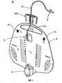
- fluid collection system 10 includes a fluid collection bag 12, a drain tube 14, a sampling port 16 connected to a first end 14a of drain tube 14 and a discharge valve 18.
- Collection bag 12 has at least one vent opening 20 for allowing air into and out of collection bag 12.
- An anti-reflux valve 22 is positioned at a second end 14b of drain tube 14. Anti-reflux valve 22 allows fluid to flow from drain tube 14 into collection bag 12 but restricts flow from collection bag 12 back into drain tube 14. Anti-reflux valve 22 can be secured directly to collection bag 12 using any known fastening technique, e.g., welding, adhesives, etc.
- Fluid collection system 10 is used to collect fluid from a catheterized patient. The fluid flows via a transfer tube (not shown), through sampling port 16 and into drain tube 14. Fluid in tube 14 enters collection bag 12 through anti-reflux valve 22 where it collects in collection bag 12. Discharge valve 18 is operable in a known manner to selectively drain the fluid from collection bag 12.
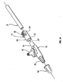
- sampling port 16 includes a substantially rigid body portion 24 defining a longitudinal channel 26 having an inlet end 28, an outlet end 30, and a transverse opening 32 (FIG. 5).
- a valve assembly 34 is supported within a cup structure 35 formed on body portion 24.
- Valve assembly 34 includes an outer valve housing 36 which is supported within cup structure 35 and defines an annular recess 38 dimensioned to receive an annular inner valve housing 40 (FIG. 5).
- Inner valve housing 40 supports outer valve housing 36 above transverse opening 32 and can be formed integrally with body portion 24 or formed separately therefrom and secured thereto.
- Valve assembly 34 can be secured within cup structure 35 using any known fastening technique, e.g., adhesives RF or ultrasonic welding, etc.
- Outer valve housing 36 defines a channel 42 which is substantially orthogonal to channel 26.
- a flexible gland 44 which can be formed from silicone is positioned within channel 42 and defines an inlet 46, a throughbore 48 and an outlet 50 which communicates with opening 32 of body portion 24.
- a valve stem 52 is supported in throughbore 48 and functions to regulate flow through valve assembly 34.
- Valve stem 52 includes an upper valve member 54 supported adjacent inlet 46 within gland 44 and a lower valve member 56 positioned adjacent outlet 50. In its unbiased position, gland 44 maintains valve stem 52 in a position to seal inlet 46 and outlet 50 of throughbore 48 to prevent flow through sampling port 16.
- Top valve housing 36 includes an outer surface having a thread 60 configured to releasably engage a luer lock or slip-tip type syringe (not shown).
- a tip of the syringe enters inlet 46 of valve 34 and urges valve stem 52 downwardly against the bias of gland 44 to open valve 34.
- fluid can be withdrawn by a syringe through opening 32 in body portion 24 of sampling port 16, such that fluid flows around valve stem 52 and exits opening 46 into the syringe.
- inlet end 28 includes a stepped portion which has a distal end 28a of smaller diameter than its proximal end 28b.
- the stepped portion is configured to engage a transfer tube (not shown) which is connected to a catheter positioned within the bladder of a patient.
- Outlet end 30 includes a frusta-conical portion which is configured to receive one end of flexible drain tube 14 or a vent 80 (FIG. 1A) as will be discussed below.
- An annular recess 64 (FIG. 5) is provided about frusto-conical portion 30 for receiving the end of drain tube 14 or vent 80. It is envisioned other attaching techniques may be used to secure sampling port 16 between drain tube 14 and the transfer tube, e.g., clamps, adhesives, etc.
- valve 34 of sampling port 16 is available from NP Medical, Inc., a division of Nypro, Inc., of Clinton, Ma. It is envisioned that other valves which function in a similar manner may also be incorporated into body portion 24 of sampling port 16.
- FIGS. 6 and 7 illustrate an alternate embodiment of the presently disclosed sampling port shown generally as 116.
- Sampling port 116 includes a body portion 124 defining a longitudinal channel 126 having an inlet end 128, an outlet end 130 and a transverse opening 132 (FIG. 7).
- Body portion 124 defines a recess or cup structure 133 configured to receive an access member 134.
- access member 134 includes a housing 136 defining a transverse throughbore 148 which is aligned with opening 132.
- a pierceable, flexible sealing member 152 is supported within housing 136 to seal throughbore 148. Sealing member 152 is formed from a material which can be pierced with the needle of a syringe to access fluid within sampling port 116 and will seal upon itself when the needle of the syringe is removed from sealing member 152.
- Inlet end 128 and outlet end 130 of body portion 124 are substantially as described above with respect to ends 26 and 28 of body portion 24 of sampling port 16 and will not be described in further detail herein.
- inlet end 128 of sampling port 116 is connected to a transfer tube (not shown) which is connected to a urinary catheter of a catheterized patient and outlet end 130 is connected to one end of drain tube 14 (FIG. 1) or to in-line vent 80 as will be described below, such that urine from the patient flows through the sampling port and the drain tube to collection bag 12.
- a clinician or medical personnel pierces sealing member 152 with a needle of a syringe (not shown) and fluid is withdrawn from sampling port 116 upstream of collection bag 12. Thereafter, the needle of the syringe is withdrawn from sealing member 152 and sealing member 152 seals the piercing.
- an in-line vent 80 can be provided between the catheterized patient (not shown) and collection bag 12.
- in-line vent 80 has a first end 82 configured to engage outlet end 30 of sampling port 16 and a second end 84 configured to engage drain tube 14.
- In-line vent 80 includes a housing 92 defining a longitudinal throughbore 85 to allow fluid to flow through the vent housing 92.
- Vent housing 92 supports a venting structure 86 which allows air to enter the system to prevent siphoning of fluid from a patient's bladder during emptying of collection bag 12. Vent 80 also minimizes back pressure in the system especially when drain 14 is hung below bag 12.
- venting structure 86 includes an oleophobic expanded PTFE membrane and housing 82 is formed from PVC.
- the oleophobic membrane can be a gortex TM material. Alternately, other materials can be used to construct the membrane.
- a cap 90 can be provided to cover end 28 of sampling port 16 prior to attachment of sampling port 16 to a catheterized patient.
- fluid collection system 10 can also include a support member 200 for supporting collection bag 12 on support structure, e.g., bedframe (not shown).
- Support member 200 includes a central body portion 202 and at least one depending hanger or hook portion 204.
- the at least one depending hook portion 204 includes a pair of hook portions 204 which extend outwardly from opposite sides of central body portion 202.
- Each hook portion 204 is pivotally connected to central body portion 202.
- Hook portions 204 can be pivotally connected to central body portion 202 by a living hinge 206.
- other pivot structure can be used to secure hook portions 204 to central body portion 202, e.g., pivot pins.
- the pivot structure facilitates repositioning of hook portions 204 in relation to central body portion 202 to more easily and securely attach a collection bag 12 (FIG. 1) to support structure (not shown).
- Central body portion 202 includes upper and lower mounting structure for securing support member 200 to collection bag 12 at vertically spaced positions.
- upper and lower mounting structure includes an upper mounting opening 208 and a lower mounting opening 210.
- Mounting openings 208 and 210 are dimensioned to receive a securement dowel or pin 214 (FIG. 1) for securing support member 200 to collection bag 12.
- Pin 214 is positioned through an opening (not shown) in collection bag 12 and one of openings 208 and 210 to selectively secure support member 200 at one of two vertically spaced locations in relation to collection bag 12.
- the height of the collection bag in relation to the support member 200 can be selectively changed to thereby vary the height of the collection bag on the support structure. Since fluid collection system 10 is a gravity flow system, openings 208 and 210 allow for the head pressure of the system to be changed by changing the vertical positioning of collection bag 12 in relation to support member 200.
- Central body portion 202 also includes a pair of spring arms 220.
- Spring arms 220 extend outwardly from central body portion 202 of support member 200 and are positioned to releasably engage drain tube 14. Spring arms 220 minimize the likelihood of drain tube 14 becoming twisted or kinked. Alternately, other tube support structure may be employed.
- Drain tube 14 and collection bag 12 are formed from a flexible material or materials, e.g., polyvinylchloride ("PVC").
- the collection bag and drain tube are formed of a material having a durometer of between about 60 and about 100 and preferably about 78.
- in-line vent and/or sampling port upstream of the collection bag can be altered and need not be exactly as shown.
- the support member may include multiple vertically spaced mounting structures, e.g., 3 or more. Therefore, the above description should not be construed as limiting, but merely as exemplifications of preferred embodiments. Those skilled in the art will envision other modifications within the scope and spirit of the claims appended hereto.
Priority Applications (1)
| Application Number | Priority Date | Filing Date | Title |
|---|---|---|---|
| PL07250764T PL1825835T3 (pl) | 2006-02-24 | 2007-02-23 | System zbierania moczu z bezigłowym otworem próbkującym |
Applications Claiming Priority (1)
| Application Number | Priority Date | Filing Date | Title |
|---|---|---|---|
| US11/362,656 US20070203463A1 (en) | 2006-02-24 | 2006-02-24 | Urine collection system with needleless sampling port |
Publications (3)
| Publication Number | Publication Date |
|---|---|
| EP1825835A2 true EP1825835A2 (fr) | 2007-08-29 |
| EP1825835A3 EP1825835A3 (fr) | 2007-09-05 |
| EP1825835B1 EP1825835B1 (fr) | 2009-04-22 |
Family
ID=38122318
Family Applications (1)
| Application Number | Title | Priority Date | Filing Date |
|---|---|---|---|
| EP07250764A Not-in-force EP1825835B1 (fr) | 2006-02-24 | 2007-02-23 | Système de collecte d'urine avec port de prélèvement sans aiguille |
Country Status (12)
| Country | Link |
|---|---|
| US (1) | US20070203463A1 (fr) |
| EP (1) | EP1825835B1 (fr) |
| CN (1) | CN101040821B (fr) |
| AT (1) | ATE429200T1 (fr) |
| CA (1) | CA2579892C (fr) |
| DE (1) | DE602007000928D1 (fr) |
| DK (1) | DK1825835T3 (fr) |
| ES (1) | ES2325971T3 (fr) |
| MX (1) | MX2007002229A (fr) |
| PL (1) | PL1825835T3 (fr) |
| PT (1) | PT1825835E (fr) |
| TW (1) | TW200740418A (fr) |
Cited By (3)
| Publication number | Priority date | Publication date | Assignee | Title |
|---|---|---|---|---|
| EP2428190A3 (fr) * | 2010-09-08 | 2014-07-09 | Covidien LP | Port de prélèvement sans aiguille |
| KR20180075587A (ko) * | 2015-10-30 | 2018-07-04 | 씨. 알. 바드, 인크. | 벤트 어댑터 조립체, 그 제작 방법, 그 사용 방법 및 이를 이용한 배뇨 백 시스템 |
| USD932025S1 (en) | 2018-01-05 | 2021-09-28 | Medline Industries, Inc. | Vented urine meter |
Families Citing this family (20)
| Publication number | Priority date | Publication date | Assignee | Title |
|---|---|---|---|---|
| US20080097411A1 (en) * | 2006-09-25 | 2008-04-24 | Jamie Glen House | Catheter assemblies having sized sheaths |
| US8430855B2 (en) | 2006-12-06 | 2013-04-30 | Medline Industries, Inc. | Fluid collection system and methods of using same |
| US7846142B2 (en) * | 2006-12-06 | 2010-12-07 | Medline Industries, Inc. | Fluid collection system and methods of using same |
| WO2009046170A1 (fr) * | 2007-10-02 | 2009-04-09 | C. R. Bard, Inc. | Capuchon d'orifice d'échantillonnage pour système de vidange d'urine de foley |
| WO2010045042A2 (fr) | 2008-10-17 | 2010-04-22 | Sterigear LLC | Ensemble d’écoulement de fluide corporel |
| US8092436B2 (en) * | 2008-10-17 | 2012-01-10 | Sterigear LLC | Bodily fluid drainage assembly |
| US20120184944A1 (en) * | 2011-01-19 | 2012-07-19 | Tomes Jennifer E | Coiled Tubing for Drain Bag Applications |
| CN104771794B (zh) * | 2011-08-11 | 2017-06-20 | 苏州林华医疗器械股份有限公司 | 一次性自控精密计量引流袋 |
| US20130245496A1 (en) * | 2012-01-09 | 2013-09-19 | Mark Edward Wells | Urinary catheter anti-reflux and pathogen block device |
| US20140039349A1 (en) * | 2012-07-31 | 2014-02-06 | Covidien Lp | Urine collection system, apparatus and method |
| CN102921092A (zh) * | 2012-10-30 | 2013-02-13 | 江苏康诺医疗器械有限公司 | 一次性使用防返流引流袋 |
| CA3038503A1 (fr) | 2016-09-29 | 2018-04-05 | Dignity Health | Systeme de catheter destine a drainer un liquide corporel a partir d'une source de liquide dans un corps |
| US20210161512A1 (en) * | 2018-05-22 | 2021-06-03 | C. R. Bard, Inc. | Urine-Sampling Kit And Methods Thereof |
| EP3796878A4 (fr) * | 2018-05-22 | 2022-03-09 | C. R. Bard, Inc. | Systèmes d'échantillonnage d'urine aseptique et procédés associés |
| US11540962B2 (en) * | 2018-11-16 | 2023-01-03 | Donna Weaver | Product bag retention assembly |
| WO2020205888A1 (fr) | 2019-04-01 | 2020-10-08 | Sterigear, Llc | Sac de drainage double, ensembles et procédés associés |
| WO2022056420A1 (fr) * | 2020-09-14 | 2022-03-17 | Merit Medical Systems, Inc. | Bouteille de collecte de drainage sous vide |
| US11241566B1 (en) | 2020-10-20 | 2022-02-08 | Erin Jessica Lindsay | Clip for urinary drainage system |
| USD977671S1 (en) | 2021-03-31 | 2023-02-07 | Merit Medical Systems, Inc. | Vacuum drainage storage bottle |
| CN113616905A (zh) * | 2021-09-10 | 2021-11-09 | 浙江医院 | 一种基于颅内压监测的脑脊液引流装置及方法 |
Citations (3)
| Publication number | Priority date | Publication date | Assignee | Title |
|---|---|---|---|---|
| GB2011523A (en) * | 1977-12-27 | 1979-07-11 | Ross Inc Will | Container support means |
| US4312352A (en) * | 1980-01-29 | 1982-01-26 | C. R. Bard, Inc. | Hanger, hook and handle assembly for urinary drainage bag |
| GB2322079A (en) * | 1997-02-13 | 1998-08-19 | Smiths Industries Plc | Urine bag assembly |
Family Cites Families (16)
| Publication number | Priority date | Publication date | Assignee | Title |
|---|---|---|---|---|
| US3299442A (en) * | 1965-10-29 | 1967-01-24 | Bard Inc C R | Bottle with hanger support |
| US3661143A (en) * | 1969-06-23 | 1972-05-09 | Henkin Melvyn Lane | Medical apparatus for drainage, collection and monitoring of body fluids |
| US3699964A (en) * | 1970-07-02 | 1972-10-24 | Bard Inc C R | Closed urinary drainage and irrigation system |
| US4219177A (en) * | 1978-08-25 | 1980-08-26 | American Hospital Supply Corporation | Bed rail hanger system |
| US4305405A (en) * | 1980-03-25 | 1981-12-15 | C. R. Bard, Inc. | Urine meter bag |
| US4501584A (en) * | 1983-03-04 | 1985-02-26 | The Kendall Company | Liquid drainage system with formed hinged support sheet |
| US4606736A (en) * | 1985-01-23 | 1986-08-19 | Van De Weghe Associates, Inc. | Cover assembly for closed bodily fluid drainage unit |
| CN86203608U (zh) * | 1986-05-22 | 1987-01-07 | 段禄轲 | 医用输液调速带 |
| US5375799A (en) * | 1992-09-25 | 1994-12-27 | Hollister Incorporated | Collection bag hanger with rail width-adjustable hook arms |
| US5582460A (en) * | 1993-06-11 | 1996-12-10 | Hon Industries Inc. | Pivotable and height-adjustable chair back rest assembly and blow-molded back rest therefor |
| US5527007A (en) * | 1993-08-24 | 1996-06-18 | Sherwood Medical Company | Movable hanger mount for chest drainage unit |
| US5620233A (en) * | 1995-06-07 | 1997-04-15 | Jami, Inc. | Adjusting mechanism for selectively positioning chair components |
| US5569225A (en) * | 1995-06-29 | 1996-10-29 | Gkr Industries, Inc. | Bodily fluid test kit and method of testing bodily fluids |
| US6132407A (en) * | 1997-02-06 | 2000-10-17 | C. R. Bard, Inc. | Outlet tube device for urinary drainage bag |
| DE19839962C1 (de) * | 1998-09-02 | 2000-04-27 | Braun Melsungen Ag | Urinmeßgerät |
| CN2560347Y (zh) * | 2002-07-29 | 2003-07-16 | 中国人民解放军第三医院 | 一次性测膀胱压式引流袋 |
-
2006
- 2006-02-24 US US11/362,656 patent/US20070203463A1/en not_active Abandoned
-
2007
- 2007-02-23 PT PT07250764T patent/PT1825835E/pt unknown
- 2007-02-23 ES ES07250764T patent/ES2325971T3/es active Active
- 2007-02-23 EP EP07250764A patent/EP1825835B1/fr not_active Not-in-force
- 2007-02-23 PL PL07250764T patent/PL1825835T3/pl unknown
- 2007-02-23 AT AT07250764T patent/ATE429200T1/de active
- 2007-02-23 CA CA2579892A patent/CA2579892C/fr not_active Expired - Fee Related
- 2007-02-23 MX MX2007002229A patent/MX2007002229A/es active IP Right Grant
- 2007-02-23 DE DE602007000928T patent/DE602007000928D1/de active Active
- 2007-02-23 DK DK07250764T patent/DK1825835T3/da active
- 2007-02-25 CN CN2007101035510A patent/CN101040821B/zh not_active Expired - Fee Related
- 2007-02-26 TW TW096106537A patent/TW200740418A/zh unknown
Patent Citations (3)
| Publication number | Priority date | Publication date | Assignee | Title |
|---|---|---|---|---|
| GB2011523A (en) * | 1977-12-27 | 1979-07-11 | Ross Inc Will | Container support means |
| US4312352A (en) * | 1980-01-29 | 1982-01-26 | C. R. Bard, Inc. | Hanger, hook and handle assembly for urinary drainage bag |
| GB2322079A (en) * | 1997-02-13 | 1998-08-19 | Smiths Industries Plc | Urine bag assembly |
Cited By (3)
| Publication number | Priority date | Publication date | Assignee | Title |
|---|---|---|---|---|
| EP2428190A3 (fr) * | 2010-09-08 | 2014-07-09 | Covidien LP | Port de prélèvement sans aiguille |
| KR20180075587A (ko) * | 2015-10-30 | 2018-07-04 | 씨. 알. 바드, 인크. | 벤트 어댑터 조립체, 그 제작 방법, 그 사용 방법 및 이를 이용한 배뇨 백 시스템 |
| USD932025S1 (en) | 2018-01-05 | 2021-09-28 | Medline Industries, Inc. | Vented urine meter |
Also Published As
| Publication number | Publication date |
|---|---|
| PL1825835T3 (pl) | 2009-11-30 |
| DE602007000928D1 (de) | 2009-06-04 |
| PT1825835E (pt) | 2009-07-20 |
| US20070203463A1 (en) | 2007-08-30 |
| MX2007002229A (es) | 2008-11-19 |
| CN101040821B (zh) | 2012-07-04 |
| CA2579892C (fr) | 2013-12-17 |
| EP1825835A3 (fr) | 2007-09-05 |
| EP1825835B1 (fr) | 2009-04-22 |
| CN101040821A (zh) | 2007-09-26 |
| ES2325971T3 (es) | 2009-09-25 |
| TW200740418A (en) | 2007-11-01 |
| ATE429200T1 (de) | 2009-05-15 |
| CA2579892A1 (fr) | 2007-08-24 |
| DK1825835T3 (da) | 2009-08-17 |
Similar Documents
| Publication | Publication Date | Title |
|---|---|---|
| EP1825835B1 (fr) | Système de collecte d'urine avec port de prélèvement sans aiguille | |
| US5441481A (en) | Microdialysis probes and methods of use | |
| US7662110B2 (en) | Devices for collecting blood and administering medical fluids | |
| US5396899A (en) | Spinal puncture fluid collection apparatus | |
| US5954687A (en) | Burr hole ring with catheter for use as an injection port | |
| US8221366B2 (en) | Volume limiting bodily fluid drainage system | |
| US7488297B2 (en) | Blood collecting devices | |
| US5919146A (en) | Urine sampling and drainage device | |
| US7588562B2 (en) | Body fluid collection apparatus | |
| US8152792B1 (en) | Subcutaneous drain for a body cavity | |
| US20030199850A1 (en) | Orthogonal arterial catheter | |
| JP2002534203A (ja) | 液体試料を得るための装置 | |
| US7207950B2 (en) | Aspiration needle with venting feature | |
| US7670312B2 (en) | Sensor system including a port body | |
| EP2803868B1 (fr) | Système de prélèvement d'échantillon fermé | |
| JP4007681B2 (ja) | 翼付採血針 | |
| CN214907018U (zh) | 一种便于人体血药浓度监控用样本采集装置 | |
| JPH02102659A (ja) | 植込み型胸管・静脈シャント |
Legal Events
| Date | Code | Title | Description |
|---|---|---|---|
| PUAI | Public reference made under article 153(3) epc to a published international application that has entered the european phase |
Free format text: ORIGINAL CODE: 0009012 |
|
| PUAL | Search report despatched |
Free format text: ORIGINAL CODE: 0009013 |
|
| AK | Designated contracting states |
Kind code of ref document: A2 Designated state(s): AT BE BG CH CY CZ DE DK EE ES FI FR GB GR HU IE IS IT LI LT LU LV MC NL PL PT RO SE SI SK TR |
|
| AX | Request for extension of the european patent |
Extension state: AL BA HR MK YU |
|
| AK | Designated contracting states |
Kind code of ref document: A3 Designated state(s): AT BE BG CH CY CZ DE DK EE ES FI FR GB GR HU IE IS IT LI LT LU LV MC NL PL PT RO SE SI SK TR |
|
| AX | Request for extension of the european patent |
Extension state: AL BA HR MK YU |
|
| 17P | Request for examination filed |
Effective date: 20080201 |
|
| REG | Reference to a national code |
Ref country code: HK Ref legal event code: DE Ref document number: 1107757 Country of ref document: HK |
|
| AKX | Designation fees paid |
Designated state(s): AT BE BG CH CY CZ DE DK EE ES FI FR GB GR HU IE IS IT LI LT LU LV MC NL PL PT RO SE SI SK TR |
|
| GRAP | Despatch of communication of intention to grant a patent |
Free format text: ORIGINAL CODE: EPIDOSNIGR1 |
|
| GRAS | Grant fee paid |
Free format text: ORIGINAL CODE: EPIDOSNIGR3 |
|
| GRAA | (expected) grant |
Free format text: ORIGINAL CODE: 0009210 |
|
| AK | Designated contracting states |
Kind code of ref document: B1 Designated state(s): AT BE BG CH CY CZ DE DK EE ES FI FR GB GR HU IE IS IT LI LT LU LV MC NL PL PT RO SE SI SK TR |
|
| REG | Reference to a national code |
Ref country code: GB Ref legal event code: FG4D |
|
| REG | Reference to a national code |
Ref country code: CH Ref legal event code: EP |
|
| REG | Reference to a national code |
Ref country code: IE Ref legal event code: FG4D |
|
| REF | Corresponds to: |
Ref document number: 602007000928 Country of ref document: DE Date of ref document: 20090604 Kind code of ref document: P |
|
| REG | Reference to a national code |
Ref country code: PT Ref legal event code: SC4A Free format text: AVAILABILITY OF NATIONAL TRANSLATION Effective date: 20090715 |
|
| REG | Reference to a national code |
Ref country code: CH Ref legal event code: NV Representative=s name: E. BLUM & CO. AG PATENT- UND MARKENANWAELTE VSP |
|
| REG | Reference to a national code |
Ref country code: DK Ref legal event code: T3 |
|
| REG | Reference to a national code |
Ref country code: SE Ref legal event code: TRGR Ref country code: GR Ref legal event code: EP Ref document number: 20090401846 Country of ref document: GR |
|
| REG | Reference to a national code |
Ref country code: ES Ref legal event code: FG2A Ref document number: 2325971 Country of ref document: ES Kind code of ref document: T3 |
|
| PG25 | Lapsed in a contracting state [announced via postgrant information from national office to epo] |
Ref country code: LT Free format text: LAPSE BECAUSE OF FAILURE TO SUBMIT A TRANSLATION OF THE DESCRIPTION OR TO PAY THE FEE WITHIN THE PRESCRIBED TIME-LIMIT Effective date: 20090422 |
|
| PG25 | Lapsed in a contracting state [announced via postgrant information from national office to epo] |
Ref country code: LV Free format text: LAPSE BECAUSE OF FAILURE TO SUBMIT A TRANSLATION OF THE DESCRIPTION OR TO PAY THE FEE WITHIN THE PRESCRIBED TIME-LIMIT Effective date: 20090422 Ref country code: IS Free format text: LAPSE BECAUSE OF FAILURE TO SUBMIT A TRANSLATION OF THE DESCRIPTION OR TO PAY THE FEE WITHIN THE PRESCRIBED TIME-LIMIT Effective date: 20090822 Ref country code: SI Free format text: LAPSE BECAUSE OF FAILURE TO SUBMIT A TRANSLATION OF THE DESCRIPTION OR TO PAY THE FEE WITHIN THE PRESCRIBED TIME-LIMIT Effective date: 20090422 |
|
| REG | Reference to a national code |
Ref country code: PL Ref legal event code: T3 |
|
| PG25 | Lapsed in a contracting state [announced via postgrant information from national office to epo] |
Ref country code: RO Free format text: LAPSE BECAUSE OF FAILURE TO SUBMIT A TRANSLATION OF THE DESCRIPTION OR TO PAY THE FEE WITHIN THE PRESCRIBED TIME-LIMIT Effective date: 20090422 Ref country code: CZ Free format text: LAPSE BECAUSE OF FAILURE TO SUBMIT A TRANSLATION OF THE DESCRIPTION OR TO PAY THE FEE WITHIN THE PRESCRIBED TIME-LIMIT Effective date: 20090422 Ref country code: EE Free format text: LAPSE BECAUSE OF FAILURE TO SUBMIT A TRANSLATION OF THE DESCRIPTION OR TO PAY THE FEE WITHIN THE PRESCRIBED TIME-LIMIT Effective date: 20090422 |
|
| PG25 | Lapsed in a contracting state [announced via postgrant information from national office to epo] |
Ref country code: SK Free format text: LAPSE BECAUSE OF FAILURE TO SUBMIT A TRANSLATION OF THE DESCRIPTION OR TO PAY THE FEE WITHIN THE PRESCRIBED TIME-LIMIT Effective date: 20090422 |
|
| PLBE | No opposition filed within time limit |
Free format text: ORIGINAL CODE: 0009261 |
|
| STAA | Information on the status of an ep patent application or granted ep patent |
Free format text: STATUS: NO OPPOSITION FILED WITHIN TIME LIMIT |
|
| 26N | No opposition filed |
Effective date: 20100125 |
|
| PG25 | Lapsed in a contracting state [announced via postgrant information from national office to epo] |
Ref country code: BG Free format text: LAPSE BECAUSE OF FAILURE TO SUBMIT A TRANSLATION OF THE DESCRIPTION OR TO PAY THE FEE WITHIN THE PRESCRIBED TIME-LIMIT Effective date: 20090722 |
|
| PGFP | Annual fee paid to national office [announced via postgrant information from national office to epo] |
Ref country code: PT Payment date: 20100203 Year of fee payment: 4 |
|
| PGFP | Annual fee paid to national office [announced via postgrant information from national office to epo] |
Ref country code: FI Payment date: 20100301 Year of fee payment: 4 |
|
| PG25 | Lapsed in a contracting state [announced via postgrant information from national office to epo] |
Ref country code: MC Free format text: LAPSE BECAUSE OF NON-PAYMENT OF DUE FEES Effective date: 20100301 |
|
| PGRI | Patent reinstated in contracting state [announced from national office to epo] |
Ref country code: IT Effective date: 20110501 |
|
| REG | Reference to a national code |
Ref country code: PT Ref legal event code: MM4A Free format text: LAPSE DUE TO NON-PAYMENT OF FEES Effective date: 20110823 |
|
| PG25 | Lapsed in a contracting state [announced via postgrant information from national office to epo] |
Ref country code: PT Free format text: LAPSE BECAUSE OF NON-PAYMENT OF DUE FEES Effective date: 20110823 |
|
| PG25 | Lapsed in a contracting state [announced via postgrant information from national office to epo] |
Ref country code: FI Free format text: LAPSE BECAUSE OF NON-PAYMENT OF DUE FEES Effective date: 20110223 |
|
| PGFP | Annual fee paid to national office [announced via postgrant information from national office to epo] |
Ref country code: GR Payment date: 20120228 Year of fee payment: 6 |
|
| PG25 | Lapsed in a contracting state [announced via postgrant information from national office to epo] |
Ref country code: CY Free format text: LAPSE BECAUSE OF FAILURE TO SUBMIT A TRANSLATION OF THE DESCRIPTION OR TO PAY THE FEE WITHIN THE PRESCRIBED TIME-LIMIT Effective date: 20090422 |
|
| PG25 | Lapsed in a contracting state [announced via postgrant information from national office to epo] |
Ref country code: HU Free format text: LAPSE BECAUSE OF FAILURE TO SUBMIT A TRANSLATION OF THE DESCRIPTION OR TO PAY THE FEE WITHIN THE PRESCRIBED TIME-LIMIT Effective date: 20091023 Ref country code: LU Free format text: LAPSE BECAUSE OF NON-PAYMENT OF DUE FEES Effective date: 20100223 |
|
| PG25 | Lapsed in a contracting state [announced via postgrant information from national office to epo] |
Ref country code: TR Free format text: LAPSE BECAUSE OF FAILURE TO SUBMIT A TRANSLATION OF THE DESCRIPTION OR TO PAY THE FEE WITHIN THE PRESCRIBED TIME-LIMIT Effective date: 20090422 |
|
| REG | Reference to a national code |
Ref country code: GR Ref legal event code: ML Ref document number: 20090401846 Country of ref document: GR Effective date: 20130904 |
|
| PG25 | Lapsed in a contracting state [announced via postgrant information from national office to epo] |
Ref country code: GR Free format text: LAPSE BECAUSE OF NON-PAYMENT OF DUE FEES Effective date: 20130904 |
|
| PGFP | Annual fee paid to national office [announced via postgrant information from national office to epo] |
Ref country code: PL Payment date: 20140203 Year of fee payment: 8 |
|
| REG | Reference to a national code |
Ref country code: HK Ref legal event code: WD Ref document number: 1107757 Country of ref document: HK |
|
| REG | Reference to a national code |
Ref country code: FR Ref legal event code: PLFP Year of fee payment: 10 |
|
| PGFP | Annual fee paid to national office [announced via postgrant information from national office to epo] |
Ref country code: NL Payment date: 20160121 Year of fee payment: 10 |
|
| PGFP | Annual fee paid to national office [announced via postgrant information from national office to epo] |
Ref country code: DE Payment date: 20160121 Year of fee payment: 10 Ref country code: IE Payment date: 20160121 Year of fee payment: 10 Ref country code: IT Payment date: 20160127 Year of fee payment: 10 Ref country code: CH Payment date: 20160121 Year of fee payment: 10 Ref country code: DK Payment date: 20160122 Year of fee payment: 10 Ref country code: ES Payment date: 20160208 Year of fee payment: 10 |
|
| PG25 | Lapsed in a contracting state [announced via postgrant information from national office to epo] |
Ref country code: PL Free format text: LAPSE BECAUSE OF NON-PAYMENT OF DUE FEES Effective date: 20150223 |
|
| PGFP | Annual fee paid to national office [announced via postgrant information from national office to epo] |
Ref country code: BE Payment date: 20160122 Year of fee payment: 10 Ref country code: FR Payment date: 20160121 Year of fee payment: 10 Ref country code: GB Payment date: 20160127 Year of fee payment: 10 Ref country code: SE Payment date: 20160126 Year of fee payment: 10 Ref country code: AT Payment date: 20160122 Year of fee payment: 10 |
|
| PG25 | Lapsed in a contracting state [announced via postgrant information from national office to epo] |
Ref country code: BE Free format text: LAPSE BECAUSE OF NON-PAYMENT OF DUE FEES Effective date: 20170228 |
|
| REG | Reference to a national code |
Ref country code: DE Ref legal event code: R119 Ref document number: 602007000928 Country of ref document: DE |
|
| REG | Reference to a national code |
Ref country code: DK Ref legal event code: EBP Effective date: 20170228 |
|
| REG | Reference to a national code |
Ref country code: CH Ref legal event code: PL |
|
| REG | Reference to a national code |
Ref country code: SE Ref legal event code: EUG |
|
| REG | Reference to a national code |
Ref country code: NL Ref legal event code: MM Effective date: 20170301 |
|
| REG | Reference to a national code |
Ref country code: AT Ref legal event code: MM01 Ref document number: 429200 Country of ref document: AT Kind code of ref document: T Effective date: 20170223 |
|
| GBPC | Gb: european patent ceased through non-payment of renewal fee |
Effective date: 20170223 |
|
| PG25 | Lapsed in a contracting state [announced via postgrant information from national office to epo] |
Ref country code: AT Free format text: LAPSE BECAUSE OF NON-PAYMENT OF DUE FEES Effective date: 20170223 Ref country code: CH Free format text: LAPSE BECAUSE OF NON-PAYMENT OF DUE FEES Effective date: 20170228 Ref country code: LI Free format text: LAPSE BECAUSE OF NON-PAYMENT OF DUE FEES Effective date: 20170228 |
|
| REG | Reference to a national code |
Ref country code: IE Ref legal event code: MM4A |
|
| PG25 | Lapsed in a contracting state [announced via postgrant information from national office to epo] |
Ref country code: NL Free format text: LAPSE BECAUSE OF NON-PAYMENT OF DUE FEES Effective date: 20170301 Ref country code: SE Free format text: LAPSE BECAUSE OF NON-PAYMENT OF DUE FEES Effective date: 20170224 |
|
| REG | Reference to a national code |
Ref country code: FR Ref legal event code: ST Effective date: 20171031 |
|
| PG25 | Lapsed in a contracting state [announced via postgrant information from national office to epo] |
Ref country code: DE Free format text: LAPSE BECAUSE OF NON-PAYMENT OF DUE FEES Effective date: 20170901 Ref country code: DK Free format text: LAPSE BECAUSE OF NON-PAYMENT OF DUE FEES Effective date: 20170228 Ref country code: FR Free format text: LAPSE BECAUSE OF NON-PAYMENT OF DUE FEES Effective date: 20170228 |
|
| REG | Reference to a national code |
Ref country code: BE Ref legal event code: MM Effective date: 20170228 |
|
| PG25 | Lapsed in a contracting state [announced via postgrant information from national office to epo] |
Ref country code: IT Free format text: LAPSE BECAUSE OF NON-PAYMENT OF DUE FEES Effective date: 20170223 Ref country code: IE Free format text: LAPSE BECAUSE OF NON-PAYMENT OF DUE FEES Effective date: 20170223 Ref country code: GB Free format text: LAPSE BECAUSE OF NON-PAYMENT OF DUE FEES Effective date: 20170223 |
|
| REG | Reference to a national code |
Ref country code: ES Ref legal event code: FD2A Effective date: 20180703 |
|
| PG25 | Lapsed in a contracting state [announced via postgrant information from national office to epo] |
Ref country code: ES Free format text: LAPSE BECAUSE OF NON-PAYMENT OF DUE FEES Effective date: 20170224 |