EP1821392A2 - Hochleistungsgenerator mit verstärkter Wärmeabfuhr - Google Patents
Hochleistungsgenerator mit verstärkter Wärmeabfuhr Download PDFInfo
- Publication number
- EP1821392A2 EP1821392A2 EP07102712A EP07102712A EP1821392A2 EP 1821392 A2 EP1821392 A2 EP 1821392A2 EP 07102712 A EP07102712 A EP 07102712A EP 07102712 A EP07102712 A EP 07102712A EP 1821392 A2 EP1821392 A2 EP 1821392A2
- Authority
- EP
- European Patent Office
- Prior art keywords
- interlamination
- stator
- generator
- rotor
- shaft
- Prior art date
- Legal status (The legal status is an assumption and is not a legal conclusion. Google has not performed a legal analysis and makes no representation as to the accuracy of the status listed.)
- Withdrawn
Links
Images


Classifications
-
- H—ELECTRICITY
- H02—GENERATION; CONVERSION OR DISTRIBUTION OF ELECTRIC POWER
- H02K—DYNAMO-ELECTRIC MACHINES
- H02K1/00—Details of the magnetic circuit
- H02K1/06—Details of the magnetic circuit characterised by the shape, form or construction
- H02K1/22—Rotating parts of the magnetic circuit
- H02K1/32—Rotating parts of the magnetic circuit with channels or ducts for flow of cooling medium
-
- H—ELECTRICITY
- H02—GENERATION; CONVERSION OR DISTRIBUTION OF ELECTRIC POWER
- H02K—DYNAMO-ELECTRIC MACHINES
- H02K9/00—Arrangements for cooling or ventilating
- H02K9/19—Arrangements for cooling or ventilating for machines with closed casing and closed-circuit cooling using a liquid cooling medium, e.g. oil
Definitions
- the present invention relates to relatively high power generators and, more particularly, to high power generators that are used with gas turbine engines such as those used in aircraft, tanks, ships, terrestrial vehicles, or other applications.
- AC generator systems to supply relatively constant frequency AC power.
- Many of the AC generator systems installed in these vehicles include three separate brushless generators, namely, a permanent magnet generator (PMG), an exciter, and a main generator.
- the PMG includes a rotor having permanent magnets mounted thereon, and a stator having a plurality of windings. When the PMG rotor rotates, the permanent magnets induce AC currents in PMG stator windings. These AC currents are typically fed to a regulator or a control device, which in turn outputs a DC current to the exciter.
- the exciter typically includes single-phase (e.g., DC) stator windings and multi-phase (e.g., three-phase) rotor windings.
- the DC current from the regulator or control device is supplied to exciter stator windings, and as the exciter rotor rotates, three phases of AC current are typically induced in the rotor windings.
- Rectifier circuits that rotate with the exciter rotor rectify this three-phase AC current, and the resulting DC currents are provided to the main generator.
- the main generator additionally includes a rotor and a stator having single-phase (e.g., DC) and multi-phase (e.g., three-phase) windings, respectively.
- the DC currents from the rectifier circuits are supplied to the rotor windings.
- three phases of AC current are induced in main generator stator windings.
- This three-phase AC current can then be provided to a load such as, for example, electrical aircraft systems.
- some of the electrical components within the generator may generate heat due to electrical losses, and may thus be supplied with a cooling medium.
- the main rotor windings and main stator windings are cooled using a cooling medium, such as a lubricant, that flows in and through the generator.
- the main rotor and main stator windings are cooled by spraying the cooling medium, via orifices in the main rotor shaft, onto end turns of the main rotor and main stator windings.
- the cooling medium flow through the main rotor shaft also provides conduction cooling of the main rotor along its axial length. Conduction cooling along the axial length of the main stator is provided via a stator back iron cooling flow path. More specifically, a portion of the cooling medium is directed through a flow path formed in or on the stator back iron.
- the cooling scheme can present certain drawbacks.
- the cooling scheme can result in insufficient cooling of the main rotor and main stator near the axially positioned centers, causing relatively high temperature hot spots at or near these locations, which can be detrimental to overall generator performance.
- a high speed, high power generator that addresses the above-noted drawback. Namely, a high speed, high power generator that supplies sufficient cooling to its main rotor and main stator even if the length to diameter ratio is increased.
- the present invention addresses at least this need.
- the present invention provides a high speed, high power generator that provides enhanced cooling of the main rotor and main stator near the axially positioned centers thereof.
- a high power generator includes a generator housing, a stator, a shaft, and a rotor.
- the stator is mounted within the generator housing.
- the shaft is rotationally mounted within the generator housing, and includes an inner surface that defines an internal fluid How passage, an outer surface, and a plurality of interlamination cooling supply orifices extending between the shaft inner and outer surfaces.
- the internal fluid flow passage is configured to receive a flow of a cooling medium, and each interlamination cooling supply orifice is in fluid communication with the internal fluid flow passage.
- the rotor is mounted on the shaft and is disposed at least partially within and is spaced apart from the stator to form an air gap there-between.
- the rotor includes a plurality of poles, and one or more interlamination disks.
- Each pole extends radially outwardly from the shaft and is formed of at least a plurality of laminations.
- Each interlamination disk is disposed between at least two of the laminations and includes a plurality of fluid inlets, a plurality of fluid outlets, and a plurality of interlamination flow passages.
- Each fluid inlet is in fluid communication with one of the shaft interlamination cooling supply orifices
- each fluid outlet is in fluid communication with the air gap
- each interlamination flow passage extends between one of the fluid inlets and one of the fluid outlets.
- a high power generator in another exemplary embodiment, includes a generator housing, a stator, a shaft, and a rotor.
- the stator is mounted within the generator housing and includes a plurality of stator core subassemblies and a plurality of main stator windings.
- Each stator core subassembly is coupled to the generator housing and is spaced apart from at least one other adjacent stator core subassembly to form an inter-stator gap there-between.
- Each stator winding has at least one end turn and extending into an inter-stator gap.
- the shaft is rotationally mounted within the generator housing, and includes an inner surface that defines an internal fluid flow passage, an outer surface, and a plurality of interlamination cooling supply orifices extending between the shaft inner and outer surfaces.
- the internal fluid flow passage is configured to receive a flow of a cooling medium, and each interlamination cooling supply orifice is in fluid communication with the internal fluid flow passage.
- the rotor is mounted on the shaft and is disposed at least partially within and is spaced apart from the stator to form an air gap there-between.
- the rotor includes a plurality of poles, and one or more interlamination disks. Each pole extends radially outwardly from the shaft and is formed of at least a plurality of laminations.
- Each interlamination disk is disposed between at least two of the laminations and includes a plurality of fluid inlets, a plurality of fluid outlets, and a plurality of interlamination flow passages.
- Each fluid inlet is in fluid communication with one of the shaft interlamination cooling supply orifices
- each fluid outlet is in fluid communication with the air gap
- each interlamination flow passage extends between one of the fluid inlets and one of the fluid outlets.
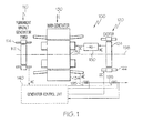
- FIG. 1 is a functional schematic diagram of an exemplary high speed generator embodiment
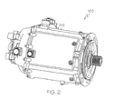
- FIG. 2 is a perspective view of a physical embodiment of the generator shown in FIG. 1;
- FIG. 3 is a simplified schematic cross section view of a portion of the exemplary generator shown in FIGS. 1 and 2 according to an embodiment of the present invention
- FIG. 4 is a front cross section view of a portion of an exemplary alternative interlamination disk that may be used to implement the generators shown in FIGS. 1-3 according to an embodiment of the present invention.
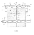
- FIG. 5 is a simplified schematic cross section view of a portion of the exemplary generator shown in FIGS. 1 and 2, which includes an exemplary alternative interlamination disk according to an embodiment of the present invention.
- FIG. 1 a functional schematic block diagram of an exemplary high speed generator system 100 for use with a gas turbine engine such as that in an aircraft is depicted.
- This exemplary generator system 100 which is commonly known as a brushless AC generator, includes a permanent magnet generator (PMG) 110, an exciter 120, a main generator 130, a generator control unit 140, and one or more rectifier assemblies 150.
- PMG permanent magnet generator
- a rotor 112 of the PMG 110, a rotor 124 of the exciter 120, and a rotor 132 of the main generator 130 all rotate.
- the rotational speed of these components may vary.
- the rotational speed may be, for example, in the range of about 12,000 to about 24,000 r.p.m., or greater.
- the PMG rotor 112 rotates, the PMG 110 generates and supplies, via a PMG stator 114, AC power to the generator control unit 140.
- the generator control unit 140 supplies direct current (DC) power to a stator 122 of the exciter 120,
- the exciter rotor 124 in turn supplies AC power to the rectifier assemblies 150.
- the output from the rectifier assemblies 150 is DC power and is supplied to the main rotor 132, which in turn outputs AC power from a main stator 134.
- the generator system 100 is capable of providing output power at a variety of frequencies and over a variety of frequency ranges. Further, typically the output power from the main generator stator 134 is three-phase AC power.
- the generator control unit 140 can regulate the power output based upon monitoring signals provided to it from monitoring devices 195.
- the PMG rotor 112, the exciter rotor 124, and the main rotor 132 are all mounted on a common shaft 136, and thus all rotate along a single axis 198 at the same rotational speed. It will be appreciated, however, that this is merely exemplary of a particular preferred embodiment. It will additionally be appreciated that the generator system 100, or at least portions of the system 100, may be housed within a generator housing 202, a perpsective view of which is illustrated in FIG. 2.
- FIG. 3 is a simplified cross section side view representative of the schematic and physical high power generators described above, it is seen that the shaft 136 includes an inner surface 302 that defines an internal fluid flow passage 304, and an outer surface 306.
- the shaft 136 receives a supply of cooling fluid such as, for example, oil or other lubricant, via an opening 308 in a first end 312 thereof.
- the supplied cooling fluid flows through the opening 308 and into and through the internal fluid flow passage 304 toward a closed second end 314 of the shaft 136.
- the shaft 136 additionally includes a plurality of end turn cooling supply orifices 316, and a plurality of interlamination cooling supply orifices 318.
- the end turn cooling supply orifices 316 and the interlamination disk cooling supply orifices 318 each extend between the shaft inner 302 and outer 306 surfaces, and are thus in fluid communication with the internal fluid flow passage 304.
- the end turn cooling supply orifices 316 and the interlamination cooling supply orifices 318 are both preferably circumferentially disposed on, and evenly spaced about, the shaft 136.
- the end turn cooling supply orifices 316 are disposed near both ends of the main rotor 132, whereas the interlamination cooling supply orifices 318 are preferably disposed substantially midway between the end turn cooling supply orifices 316. It will be appreciated that the end turn cooling supply orifices 316 may alternatively be provided near only one end of the main rotor 132. Moreover, while the interlamination cooling supply orifices 318 are preferably disposed near an axial center of the main rotor 132, it will be appreciated that these orifices 318 may be otherwise disposed, if so needed or desired.
- the main rotor 132 is mounted on the shaft 136, and includes a plurality of poles 322, and a plurality of coils 324 (for clarity, only one shown).
- the poles 322 extend radially away from the shaft 136 and, as is generally known, are preferably spaced evenly apart from one another.
- the poles 322 are formed of a plurality of laminations 326 and an interlamination disk 328, both of which are shrunk fit onto, or otherwise coupled to, the shaft 136.
- the rotor laminations 326 as is generally known, are continuous stacks of a magnetically permeable material. The particular material may be any one of numerous magnetically permeable materials.
- the laminations 326 are formed of a magnetic alloy material such as, for example, vanadium permendur. It will be appreciated that this material is only exemplary, and that other suitable materials can be used for the rotor laminations 326.
- the interlamination disk 328 is disposed between at least two of the rotor laminations 326, and includes a plurality of fluid inlets 332, a plurality of fluid outlets 334, and a plurality of interlamination flow passages 336. It will be appreciated, however, that for clarity and ease of illustration, only two fluid inlets 332, one fluid outlet 334, and two interlamination flow passages 336 are depicted in FIG. 3. Preferably, each interlamination disk fluid inlet 332 is collocated with at least one of the interlamination cooling supply orifices 318 formed in the shaft 136.
- each interlamination flow passage 336 which extends between one of the fluid inlets 332 and one of the fluid outlets 334, is in fluid communication with the shaft internal fluid flow passage 304.
- the interlamination disk 328 is formed of a high-strength material such as, for example, magnetic iron or other magnetically permeable metal or metal alloy. It will be appreciated that this material is merely exemplary, and that other suitable materials may be used to form the interlamination disk 328. It will additionally be appreciated that the main rotor 132 may be implemented with more than one interlamination disk 328, if needed or desired.
- each rotor coil 324 is wrapped, one each, around a pole 322, and are preferably formed by wrapping numerous individual wire windings around one of the poles 322.
- each rotor coil 324 includes two end turns 332 (e.g., 332-1, 332-2), each of which is made up of wire segments that loop around ends of the pole 322.
- cooling fluid supplied to the shaft internal fluid flow passage 304 is directed, via centrifugal force, through the end turn cooling supply orifices 316 and the interlamination cooling supply orifices 318.
- the cooling fluid that is directed through the end turn cooling supply orifices 316 is sprayed onto, among other things, the rotor coil end turns 332. This cooling fluid spray provides cooling to the rotor coil end turns 332 and, as will be described further below, to portions of the main stator 134.
- the cooling fluid that is directed through the interlamination cooling supply orifices 318 flows into and through the interlamination disk fluid inlets 332, into and through the interlamination disk flow passages 336, and out the interlamination disk fluid outlets 334.
- the cooling fluid flowing through the interlamination disk flow passages 336 together with the cooling fluid flowing through the shaft internal fluid flow passage 304, provides conduction cooling for the main rotor laminations 326. It will thus be appreciated that if the main rotor 132 is implemented with a plurality of interlamination disks 328, a more uniform temperature throughout the main rotor 132 can be achieved.
- the cooling fluid that flows out the interlamination disk fluid outlets 334 is directed onto, and provides cooling for, the main stator 134, an embodiment of which will now be described in more detail.
- the main stator 134 is also mounted within the generator housing 202, and is positioned such that it is spaced apart from, and surrounds at least a portion of, the main rotor 132 to form an air gap 340 there-between.
- the main stator 134 includes a stator core 338 and a plurality of stator coils 342, and is coupled to the generator housing 202.
- the stator core 338 is preferably implemented using a plurality of spaced apart stator core sub-assemblies. In the depicted embodiment, the stator core 338 is implemented using two stator core subassemblies 344-1, 344-2, which are spaced apart from each other to form an inter-stator gap 346 there-between.
- stator core 338 could be implemented with more than this number of stator core subassemblies 344 and inter-stator gaps 346.
- stator core 338 could be implemented with "N" stator core subassemblies (e.g., 344-1, 344-2, 344-3, ... 344-N), and with "N-1" inter-stator gaps (e.g., 346-1, 346-2, 346-3, ... 346-(N-1)) formed between adjacent stator core subassemblies 344.
- stator core subassemblies 344 may vary, preferably the number of stator core subassemblies 344 is selected such that the number of inter-stator gaps 346 formed between adjacent stator core subassemblies 344 matches the number of interlamination disks 328 in the main rotor 132.
- stator core subassemblies 344 each is preferably formed of a plurality of laminations 349.
- the stator core subassembly laminations 349 are stacks of a magnetically permeable material, which may be any one of numerous magnetically permeable materials such as, for example, vanadium permendur or silicon iron.
- stator coils 342 are wrapped around each of the stator core subassemblies 344, preferably within non-illustrated slots formed in the stator core stator core subassemblies 344. Similar to the rotor coils 324, the stator coils 342 include a pair of end turns 348 (e.g., 348-1, 348-2). It will thus be appreciated that a portion of the cooling fluid spray that is directed onto the rotor coil end turns 332 is also directed onto the stator coil end turns 348, and provides cooling thereto. In addition to this, the stator coils 342 extend across the inter-stator gap 346 formed between the stator core subassemblies 338.
- a portion of the cooling fluid that flows out the interlamination disk fluid outlets 334 is directed into the inter-stator gap 346.
- the cooling fluid directed into the inter-stator gap 346 is directed onto, and flows over, the stator coils 342 within the gap 346 and a portion of the stator core subassembly laminations 349, providing additional conduction cooling for both the stator core 338 and the stator coils 342.
- the cooling fluid may be directed into the inter-stator gap 346 at a relatively high velocity, which may lead to erosion of the stator coils 342 within the inter-stator gap 346.
- the velocity of the cooling fluid in the interlamination disk flow passages 336 is preferably reduced prior to being discharged from the main rotor 132.
- this velocity reduction is implemented by directing a portion of the cooling fluid toward the rotor laminations 326 on one or both sides of the interlamination disk 328. It will be appreciated that this may be accomplished in any one, or combination, of numerous ways. For example, and as shown in FIGS.
- the interlamination disk 328 may be configured such that the interlamination flow passages 336 and at least portions of the interlamination disk 328 have radii that are less than the rotor laminations 326 between which it is disposed.
- the interlamination disk 328 may additionally include one or more velocity reduction flow passages 402 (see FIG. 4) or 502 (see FIG. 5) in fluid communication with each interlamination flow passage 336.
- the interlamination disk fluid outlet 334 upon exiting the interlamination disk fluid outlet 334, at least a portion of the cooling fluid is directed against the rotor laminations 326, causing a reduction in velocity.
- the interlamination disk 328 is preferably configured such that the velocity reduction flow passages 402 cause the cooling medium to be sprayed in a direction 404 that is generally opposite the direction 406 in which the rotor 132 is rotating.
- the velocity reduction flow passages 402, 502 are each shown disposed substantially perpendicular to its associated interlamination flow passage 336, it will be appreciated that one or more of the velocity reduction flow passages 402, 502 may be disposed at another predetermined angle relative to its associated interlamination flow passage 336.
- the generator housing 202 includes a collection cavity 352.
- the collection cavity 352 which may be integrally formed as part of the housing 202 or separately formed and coupled to the housing 202, is in fluid communication with the inter-stator gap 346 via a collection flow passage 354.
- the collection cavity 352 is additionally in fluid communication with a collection reservoir, such as a non-illustrated sump disposed within the generator housing 202. With this arrangement, the cooling fluid that is directed into the inter-stator gap 346 is directed into the collection cavity 352, and is in turn directed into the non-illustrated sump.
- the generator housing 202 may include more than one collection cavity 352 and collection flow passage 354, if needed or desired.
- the generator housing 202 is preferably implemented with one collection cavity 352 and one collection flow passage 354 per inter-stator gap 346.
- the stator core 338 is implemented to include more than one inter-stator gap 346, the generator housing 202 will concomitantly be implemented with more than one collection cavity 352 and one collection flow passage 354.
- the high speed, high power generator described herein provides enhanced cooling of the main rotor and main stator, most notably near axially positioned centers thereof.
- the generator also provides enhanced cooling of the stator coils, again most notably near the center of the main stator.
- the axial length of the generator can be increased, if needed to meet increase power generation demands, without adversely impacting thermal management of the generator.
- the efficiency of the generator may be adversely affected by directing cooling fluid into the air gap between the main rotor and main stator, the reduction in temperature that is realized mitigates this potential drawback.
Landscapes
- Engineering & Computer Science (AREA)
- Power Engineering (AREA)
- Motor Or Generator Cooling System (AREA)
- Iron Core Of Rotating Electric Machines (AREA)
Applications Claiming Priority (1)
| Application Number | Priority Date | Filing Date | Title |
|---|---|---|---|
| US11/359,115 US7476994B2 (en) | 2006-02-21 | 2006-02-21 | High power generator with enhanced heat removal |
Publications (2)
| Publication Number | Publication Date |
|---|---|
| EP1821392A2 true EP1821392A2 (de) | 2007-08-22 |
| EP1821392A3 EP1821392A3 (de) | 2009-03-18 |
Family
ID=38141195
Family Applications (1)
| Application Number | Title | Priority Date | Filing Date |
|---|---|---|---|
| EP07102712A Withdrawn EP1821392A3 (de) | 2006-02-21 | 2007-02-20 | Hochleistungsgenerator mit verstärkter Wärmeabfuhr |
Country Status (2)
| Country | Link |
|---|---|
| US (1) | US7476994B2 (de) |
| EP (1) | EP1821392A3 (de) |
Cited By (5)
| Publication number | Priority date | Publication date | Assignee | Title |
|---|---|---|---|---|
| US9985501B2 (en) | 2013-08-16 | 2018-05-29 | Hamilton Sundstrand Corporation | Generators with open loop active cooling |
| EP3518394A1 (de) * | 2018-01-25 | 2019-07-31 | GE Aviation Systems LLC | Generatorrotor mit spulenendwindungsrückhaltemechanismus |
| WO2019197172A1 (en) * | 2018-04-10 | 2019-10-17 | Safran Electrical & Power | A cooling arrangement for a generator |
| CN112636520A (zh) * | 2019-10-08 | 2021-04-09 | 德西福格成型技术有限公司 | 电机、支承装置的布置以及用于制造这种电机的方法 |
| CN113746238A (zh) * | 2017-03-24 | 2021-12-03 | 通用电气航空系统有限责任公司 | 电机方法和组件 |
Families Citing this family (18)
| Publication number | Priority date | Publication date | Assignee | Title |
|---|---|---|---|---|
| US8198762B2 (en) * | 2008-01-31 | 2012-06-12 | Pratt & Whitney Canada Corp. | Winding end turn cooling in an electric machine |
| KR101042013B1 (ko) * | 2009-03-09 | 2011-06-16 | 한국전기연구원 | 초전도 회전기의 고정자 냉각 구조 |
| US8143759B2 (en) * | 2009-04-30 | 2012-03-27 | Hamilton Sundstrand Corporation | Laminated stator assembly |
| US20110042967A1 (en) * | 2009-08-19 | 2011-02-24 | Winter Curt B | Electric generator driven by combustion engine and having fluid cooling |
| US20110089777A1 (en) * | 2009-10-18 | 2011-04-21 | Ernesto Camilo Rivera | Thermally manageable system and electric device |
| KR20130110142A (ko) * | 2010-06-08 | 2013-10-08 | 레미 테크놀러지스 엘엘씨 | 전기 기기 냉각 시스템 및 전기 기기 냉각 방법 |
| US9373984B2 (en) * | 2011-06-29 | 2016-06-21 | General Electric Company | Electrical machine |
| CN104823360B (zh) | 2012-09-06 | 2018-02-13 | 开利公司 | 电动机转子和气隙冷却 |
| US8796875B2 (en) * | 2012-11-20 | 2014-08-05 | Turbogen, Llc | Housing apparatus for use with an electrical system and method of using same |
| JP5812047B2 (ja) * | 2013-07-05 | 2015-11-11 | トヨタ自動車株式会社 | 回転電機 |
| GB2544275B (en) * | 2015-11-09 | 2022-02-16 | Time To Act Ltd | Cooling means for direct drive generators |
| DE102015223462A1 (de) * | 2015-11-26 | 2017-06-01 | Siemens Aktiengesellschaft | Rotor, flüssigkeitsgekühlte, elektrische Maschine sowie Fahrzeug |
| US11022004B2 (en) * | 2017-03-31 | 2021-06-01 | The Boeing Company | Engine shaft integrated motor |
| US10778056B2 (en) | 2017-05-16 | 2020-09-15 | Hamilton Sunstrand Corporation | Generator with enhanced stator cooling and reduced windage loss |
| JP7031619B2 (ja) * | 2019-01-23 | 2022-03-08 | トヨタ自動車株式会社 | 回転電機 |
| KR102649706B1 (ko) * | 2019-04-12 | 2024-03-19 | 엘지마그나 이파워트레인 주식회사 | 모터 |
| JP7334635B2 (ja) * | 2020-02-05 | 2023-08-29 | トヨタ自動車株式会社 | 回転電機 |
| DE102021213812A1 (de) | 2021-12-06 | 2023-06-07 | Valeo Eautomotive Germany Gmbh | Rotor für eine elektrische Maschine mit einem radialen Kühlkanal im Blechpaket |
Citations (5)
| Publication number | Priority date | Publication date | Assignee | Title |
|---|---|---|---|---|
| US3024366A (en) * | 1958-06-11 | 1962-03-06 | Yanagimachi Masanosuke | Electric generator system |
| US3189769A (en) * | 1961-08-01 | 1965-06-15 | Gen Electric | Dynamoelectric machine rotor cooling |
| US3188833A (en) * | 1959-11-23 | 1965-06-15 | Allis Louis Co | Electric motor with improved cooling means |
| US3439203A (en) * | 1965-08-31 | 1969-04-15 | Tokyo Shibaura Electric Co | Rotor of an electrical rotary machine |
| US20040066098A1 (en) * | 2002-10-04 | 2004-04-08 | Doherty Kieran P.J. | High speed generator with the main rotor housed inside the shaft |
Family Cites Families (23)
| Publication number | Priority date | Publication date | Assignee | Title |
|---|---|---|---|---|
| US1316790A (en) * | 1919-09-23 | m ax-gbitjbeb | ||
| US397340A (en) * | 1889-02-05 | Dynamo | ||
| US3217193A (en) * | 1963-03-08 | 1965-11-09 | Worthington Corp | Liquid cooled motor arrangement |
| CH461617A (de) * | 1966-04-07 | 1968-08-31 | Licentia Gmbh | Elektrische Maschine mit Abschnittskühlung |
| US3441758A (en) * | 1967-02-03 | 1969-04-29 | Gen Electric | Dynamoelectric machine cooling arrangement |
| US3480810A (en) * | 1968-06-05 | 1969-11-25 | Bendix Corp | Oil cooled generator |
| US3659125A (en) * | 1970-09-10 | 1972-04-25 | Westinghouse Electric Corp | Non-clogging nozzle for rotating equipment such as for cooling dynamo-electric machines |
| US3684906A (en) * | 1971-03-26 | 1972-08-15 | Gen Electric | Castable rotor having radially venting laminations |
| US4264834A (en) * | 1976-06-01 | 1981-04-28 | General Electric Company | Flexible serrated abradable stator mounted air gap baffle for a dynamoelectric machine |
| US4286183A (en) * | 1977-03-17 | 1981-08-25 | Westinghouse Electric Corp. | Dynamoelectric machine |
| US4203044A (en) * | 1978-01-16 | 1980-05-13 | Sundstrand Corporation | Double-walled rotor for an oil-cooled electrical machine |
| US4496862A (en) * | 1983-08-05 | 1985-01-29 | Sundstrand Corporation | High speed generator air vent for air gap |
| US4609840A (en) * | 1984-11-05 | 1986-09-02 | General Electric Company | Baffle for improving coolant gas flow distribution in the gap region of a gas cooled dynamoelectric machine |
| US4691133A (en) * | 1986-07-08 | 1987-09-01 | Electromagnetic Launch Research, Inc. | Iron-free rotary disk electrical machine |
| US5019733A (en) * | 1987-09-25 | 1991-05-28 | Honda Giken Kogyo Kabushiki Kaisha | AC generator |
| CA2010670C (en) * | 1990-02-22 | 1997-04-01 | James H. Dymond | Salient pole rotor for a dynamoelectric machine |
| US5509381A (en) * | 1992-10-29 | 1996-04-23 | Ormat Industries Ltd. | Method of and means for cooling and lubricating an alternator |
| US6727609B2 (en) * | 2001-08-08 | 2004-04-27 | Hamilton Sundstrand Corporation | Cooling of a rotor for a rotary electric machine |
| US6703729B2 (en) * | 2001-08-15 | 2004-03-09 | General Electric Company | Reverse flow stator ventilation system for superconducting synchronous machine |
| US6750572B2 (en) * | 2002-03-01 | 2004-06-15 | Honeywell International, Inc. | Generator with improved lubrication and cooling system |
| GB2393584B (en) * | 2002-09-26 | 2006-06-21 | Alstom | Gas-cooled generator |
| US6943469B2 (en) * | 2002-11-01 | 2005-09-13 | Siemens Westinghouse Power Corporation | Supplemented zonal ventilation system for electric generator |
| US7015617B2 (en) * | 2003-07-29 | 2006-03-21 | Honeywell International, Inc. | High speed generator with rotor coil support assemblies secured to interlamination disks |
-
2006
- 2006-02-21 US US11/359,115 patent/US7476994B2/en active Active
-
2007
- 2007-02-20 EP EP07102712A patent/EP1821392A3/de not_active Withdrawn
Patent Citations (5)
| Publication number | Priority date | Publication date | Assignee | Title |
|---|---|---|---|---|
| US3024366A (en) * | 1958-06-11 | 1962-03-06 | Yanagimachi Masanosuke | Electric generator system |
| US3188833A (en) * | 1959-11-23 | 1965-06-15 | Allis Louis Co | Electric motor with improved cooling means |
| US3189769A (en) * | 1961-08-01 | 1965-06-15 | Gen Electric | Dynamoelectric machine rotor cooling |
| US3439203A (en) * | 1965-08-31 | 1969-04-15 | Tokyo Shibaura Electric Co | Rotor of an electrical rotary machine |
| US20040066098A1 (en) * | 2002-10-04 | 2004-04-08 | Doherty Kieran P.J. | High speed generator with the main rotor housed inside the shaft |
Cited By (11)
| Publication number | Priority date | Publication date | Assignee | Title |
|---|---|---|---|---|
| US9985501B2 (en) | 2013-08-16 | 2018-05-29 | Hamilton Sundstrand Corporation | Generators with open loop active cooling |
| US10587170B2 (en) | 2013-08-16 | 2020-03-10 | Hamilton Sundstrand Corporation | Generators with open loop active cooling |
| CN113746238A (zh) * | 2017-03-24 | 2021-12-03 | 通用电气航空系统有限责任公司 | 电机方法和组件 |
| EP3518394A1 (de) * | 2018-01-25 | 2019-07-31 | GE Aviation Systems LLC | Generatorrotor mit spulenendwindungsrückhaltemechanismus |
| CN110086283A (zh) * | 2018-01-25 | 2019-08-02 | 通用电气航空系统有限责任公司 | 具有线圈端匝保持机构的发电机转子 |
| CN110086283B (zh) * | 2018-01-25 | 2020-12-25 | 通用电气航空系统有限责任公司 | 具有线圈端匝保持机构的发电机转子 |
| US11038394B2 (en) | 2018-01-25 | 2021-06-15 | Ge Aviation Systems Llc | Generator rotor with coil end-turn retention mechanism |
| WO2019197172A1 (en) * | 2018-04-10 | 2019-10-17 | Safran Electrical & Power | A cooling arrangement for a generator |
| US11251669B2 (en) | 2018-04-10 | 2022-02-15 | Safran Electrical & Power | Cooling arrangement for a generator |
| GB2572782B (en) * | 2018-04-10 | 2023-05-24 | Safran Electrical & Power | A Cooling Arrangement for a Generator |
| CN112636520A (zh) * | 2019-10-08 | 2021-04-09 | 德西福格成型技术有限公司 | 电机、支承装置的布置以及用于制造这种电机的方法 |
Also Published As
| Publication number | Publication date |
|---|---|
| US20070194638A1 (en) | 2007-08-23 |
| EP1821392A3 (de) | 2009-03-18 |
| US7476994B2 (en) | 2009-01-13 |
Similar Documents
| Publication | Publication Date | Title |
|---|---|---|
| US7476994B2 (en) | High power generator with enhanced heat removal | |
| US7786630B2 (en) | Spray cooled V-wedge for aerospace generator | |
| US6727609B2 (en) | Cooling of a rotor for a rotary electric machine | |
| US6750572B2 (en) | Generator with improved lubrication and cooling system | |
| EP1443189B1 (de) | Turbolader mit elektrischem Hilfsantrieb | |
| US7687928B2 (en) | Dual-structured aircraft engine starter/generator | |
| US7825552B2 (en) | Cooling arrangement for a variable reluctance electric machine | |
| EP1235331B1 (de) | Wechselstromgenerator für kraftfahrzeuge | |
| US7439646B2 (en) | High power generator with enhanced stator heat removal | |
| US6982506B1 (en) | Cooling of high speed electromagnetic rotor with fixed terminals | |
| CN109209642B (zh) | 电机设备 | |
| WO2004025810A1 (en) | High speed generator with integrally formed rotor coil support wedges | |
| EP4220908A1 (de) | Verfahren und vorrichtung zur kühlung einer rotoranordnung | |
| EP1322025B1 (de) | Wechselstromgenerator für kraftfahrzeuge | |
| WO2022223810A1 (en) | Cooling of an electric motor | |
| JP7359649B2 (ja) | 回転電機、及び回転電機システム | |
| US20090096317A1 (en) | Rotating machine | |
| EP4220907A1 (de) | Verfahren und vorrichtung zur kühlung einer rotoranordnung | |
| US11837917B2 (en) | Method and apparatus for cooling a rotor assembly | |
| US11984766B2 (en) | Method and apparatus for cooling a rotor assembly | |
| EP4311078B1 (de) | Axialflussmaschine mit direkter magnetkühlung | |
| EP4292201A1 (de) | Strömungskopf zur führung eines fluids zu und von kühlkanälen in einem motor mit hoher dichte | |
| EP4292202A1 (de) | Kühlkanäle in einem motor mit hoher dichte | |
| WO2004090919A1 (en) | Rotating transformer |
Legal Events
| Date | Code | Title | Description |
|---|---|---|---|
| PUAI | Public reference made under article 153(3) epc to a published international application that has entered the european phase |
Free format text: ORIGINAL CODE: 0009012 |
|
| AK | Designated contracting states |
Kind code of ref document: A2 Designated state(s): AT BE BG CH CY CZ DE DK EE ES FI FR GB GR HU IE IS IT LI LT LU LV MC NL PL PT RO SE SI SK TR |
|
| AX | Request for extension of the european patent |
Extension state: AL BA HR MK YU |
|
| PUAL | Search report despatched |
Free format text: ORIGINAL CODE: 0009013 |
|
| AK | Designated contracting states |
Kind code of ref document: A3 Designated state(s): AT BE BG CH CY CZ DE DK EE ES FI FR GB GR HU IE IS IT LI LT LU LV MC NL PL PT RO SE SI SK TR |
|
| AX | Request for extension of the european patent |
Extension state: AL BA HR MK RS |
|
| AKX | Designation fees paid | ||
| REG | Reference to a national code |
Ref country code: DE Ref legal event code: 8566 |
|
| STAA | Information on the status of an ep patent application or granted ep patent |
Free format text: STATUS: THE APPLICATION IS DEEMED TO BE WITHDRAWN |
|
| 18D | Application deemed to be withdrawn |
Effective date: 20090919 |