EP1821371A2 - System und Verfahren zum Verbinden von USB-Steckern - Google Patents
System und Verfahren zum Verbinden von USB-Steckern Download PDFInfo
- Publication number
- EP1821371A2 EP1821371A2 EP07250590A EP07250590A EP1821371A2 EP 1821371 A2 EP1821371 A2 EP 1821371A2 EP 07250590 A EP07250590 A EP 07250590A EP 07250590 A EP07250590 A EP 07250590A EP 1821371 A2 EP1821371 A2 EP 1821371A2
- Authority
- EP
- European Patent Office
- Prior art keywords
- socket
- plug
- housing
- standard
- plugged
- Prior art date
- Legal status (The legal status is an assumption and is not a legal conclusion. Google has not performed a legal analysis and makes no representation as to the accuracy of the status listed.)
- Withdrawn
Links
Images
Classifications
-
- H—ELECTRICITY
- H01—ELECTRIC ELEMENTS
- H01R—ELECTRICALLY-CONDUCTIVE CONNECTIONS; STRUCTURAL ASSOCIATIONS OF A PLURALITY OF MUTUALLY-INSULATED ELECTRICAL CONNECTING ELEMENTS; COUPLING DEVICES; CURRENT COLLECTORS
- H01R13/00—Details of coupling devices of the kinds covered by groups H01R12/70 or H01R24/00 - H01R33/00
- H01R13/64—Means for preventing incorrect coupling
-
- H—ELECTRICITY
- H01—ELECTRIC ELEMENTS
- H01R—ELECTRICALLY-CONDUCTIVE CONNECTIONS; STRUCTURAL ASSOCIATIONS OF A PLURALITY OF MUTUALLY-INSULATED ELECTRICAL CONNECTING ELEMENTS; COUPLING DEVICES; CURRENT COLLECTORS
- H01R12/00—Structural associations of a plurality of mutually-insulated electrical connecting elements, specially adapted for printed circuits, e.g. printed circuit boards [PCB], flat or ribbon cables, or like generally planar structures, e.g. terminal strips, terminal blocks; Coupling devices specially adapted for printed circuits, flat or ribbon cables, or like generally planar structures; Terminals specially adapted for contact with, or insertion into, printed circuits, flat or ribbon cables, or like generally planar structures
- H01R12/70—Coupling devices
- H01R12/71—Coupling devices for rigid printing circuits or like structures
-
- G—PHYSICS
- G06—COMPUTING OR CALCULATING; COUNTING
- G06F—ELECTRIC DIGITAL DATA PROCESSING
- G06F21/00—Security arrangements for protecting computers, components thereof, programs or data against unauthorised activity
- G06F21/70—Protecting specific internal or peripheral components, in which the protection of a component leads to protection of the entire computer
- G06F21/82—Protecting input, output or interconnection devices
- G06F21/85—Protecting input, output or interconnection devices interconnection devices, e.g. bus-connected or in-line devices
Definitions
- the present invention relates to the field of USB connectors. More particularly, the present invention relates to a USB male connecting device that is operationally plugged into a USB female connecting device.
- USB Universal Serial Bus
- USB A Type connector such as USB A Type plug, available from ACON, Advanced-Connectek, Inc.
- ACON Advanced-Connectek, Inc.
- USB A Type plug is a flat form factor type of connector commonly used at the end of a cable of a device that plugs into the host/computer USB port or USB hub.
- One example of such a business situation is a case of cooperation between a vendor of a portable media storage device and a vendor of a digital media playing device, wherein the cooperation implies that the storage device will be able to connect to a standard USB device for uploading content, and then to connect to only a specific media playing device for downloading the digital media.
- embodiments of the present invention seek to alleviate a problem that is not addressed by the prior art techniques, by introducing a USB connecting device and method for selectively plugging only an authorized male connector into a respective female connector.
- a system including: (a) a plug device that is configured to be reversibly operationally plugged into a socket, the socket configured according to a standard (such as the USB standard and the Firewire standard); and (b) a socket device that is configured with at least one restriction structure to prevent a plug that is configured according to the standard from being operationally plugged into the socket device, wherein the plug device is configured with a respective at least one accommodating structure to be reversibly operationally plugged into the socket device despite the restriction structure.
- a standard such as the USB standard and the Firewire standard
- the restriction structure of the socket device includes at least one protrusion.
- the socket device includes: (i) a socket housing; and (ii) a plurality of socket pins, such that the restriction structure of the socket device is configured on a surface of the socket housing that is opposite the plurality of socket pins.
- the plug device includes: (iii) a plug housing; and (iv) a plurality of plug pins, wherein at least one the accommodating structure of the plug device is configured on a surface of the plug housing that is opposite the plurality of plug pins.
- the socket device includes: (i) a socket housing; and (ii) a plurality of socket pins, such that the restriction structure of the socket device is configured on a surface of the socket housing that is adjacent the plurality of socket pins.
- the plug device includes: (iii) a plug housing; and (iv) a plurality of plug pins, wherein at least one the accommodating structure of the plug device is configured on a surface of the plug housing that is adjacent to the plurality of plug pins.
- the restriction structure includes a structure that is configured on a side surface of a housing of the housing device.
- the restriction structure includes at least two structures that are configured on a housing of the socket device at at least two locations, such as a surface of the housing that is opposite pins of the socket device, a surface of the housing that is adjacent the pins of the socket device, a side surface of the housing, etc.
- the restriction structure includes a material that is attached to the socket device.
- the restriction structure includes a dent extending inwards within a housing of the socket device.
- the system further includes two electric conductors embedded within the socket device, such that the plug device provides an electrically conductive path between the two electric conductors when the plug device is plugged into the socket device.
- the accommodating structure of the plug device includes at least one recess.
- the standard is a USB standard.
- the standard is a Firewire standard.
- the system further includes a media player for playing digital media that is configured with the socket device.
- the system further includes a media carrier (including a non-volatile memory for storing digital information) that is configured with the plug device.
- a media carrier including a non-volatile memory for storing digital information
- a system including: (a)
- the system further includes a media player for playing digital media that is operationally connected to the plug device.
- the system further includes a media carrier, including a non-volatile memory for storing digital information, which is operationally connected to the socket device.
- a media carrier including a non-volatile memory for storing digital information, which is operationally connected to the socket device.
- a method of digital rights management including the steps of: (a) configuring a media player with a socket device, having at least one restriction structure, to prevent a plug that is configured according to a standard from being operationally plugged into the socket device; (b) storing digital information in at least one media carrier; and (c) configuring the media carrier with a plug device to be reversibly operationally plugged into a socket that is configured according to this standard, wherein the plug device is configured with a respective at least one accommodating structure to be reversibly operationally plugged into the socket device despite the restriction structure, whereby allowing the media carrier, of which its plug device includes the accommodating structure, to download the digital information to the media player.
- the media carrier of which its plug device includes the accommodating structure, is allowed to download the digital information to the media player.
- a method of digital rights management including the steps of: (a) configuring a media player with a plug device, having at least one restriction structure, to prevent a socket that is configured according to a standard from being operationally plugged into the plug device; (b) storing digital information in at least one media carrier; and (c) configuring the media carrier with a socket device for being reversibly operationally plugged into a plug that is configured according to this standard, wherein the socket device is configured with a respective at least one accommodating structure for being reversibly operationally plugged into the plug device despite the restriction structure, whereby allowing said the media carrier, of which its socket device includes the accommodating structure, to download the digital information to the media player.
- the media carrier of which its socket device includes the accommodating structure, is allowed to download the digital information to the media player.
- Preferred embodiments of the present invention include a system that includes a selective socket device and a selective plug device, which are configured to prevent plugging a standard plug (e.g. a standard USB male connector) into a socket of the present invention (e.g. a USB female connector of the present invention), while allowing a plug embodying the present invention to be plugged into either a standard socket or a socket embodying the present invention.
- a standard plug e.g. a standard USB male connector
- a socket of the present invention e.g. a USB female connector of the present invention
- a standard socket is configured according to a standard (such as the USB standard and the Firewire standard) to allow enhanced connectivity and data transfer for video, audio and other storage peripheral applications.
- a standard such as the USB standard and the Firewire standard
- a socket embodying the present invention is a selective socket that features a protrusion to prevent from plugging an unauthorised plug into a socket embodying the present invention.
- a socket embodying the present invention is configured to accommodate only a plug embodying the present invention.
- a socket embodying the present invention is a modified socket device, including a restriction structure that is configured to prevent plugging a standard plug into a socket embodying the present invention.
- a plug embodying the present invention includes an accommodation structure (such as a recess) for accommodating the restriction structure of the socket, thus enabling to plug the plug into a socket embodying the present invention as well as into any other standard socket.
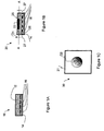
- Socket 10 includes a housing 12, typically made of metal, and a printed circuit board 14.
- Four conductor pins 16 are configured within the printed circuit board 14.
- USB socket 20 is used here only as an example and it will be clear to those skilled in the art to apply the principles of the present invention to any kind of plug/socket combination.
- Socket 20 includes a housing 21 having a printed circuit board 14 with four conductive pins 16 and a protrusion 22 that is designed to selectively prevent plugging an unauthorized plug (e.g. USB plug 40 of Figure 2A) into socket 20. Hence, only plug 50 of Figure 2B can be properly plugged into socket 20.
- an unauthorized plug e.g. USB plug 40 of Figure 2A
- protrusion 22 is placed on the inward-facing surface at the broad side 25 of housing 21 that is remote from the printed circuit board 14 and conductor pins 16, opposite printed circuit board 14, as shown.
- protrusion 22 is placed on the inward-facing surface at the broad side 26 of housing 21 that is closest to the printed circuit board 14 and conductor pins 16 or at a side inward-facing surface (i.e. the inward facing surface of wall 27 of housing 21 ).
- more than one protrusion 22 is placed in housing 21, for example on either broad side of housing 21.
- Protrusion 22 as illustrated in Figure 1B is an integral part of housing 21, protruding into the interior volume of housing 21.
- protrusion 22 is a dent in housing 21, extending inwards into the volume of housing 21 or is an additional piece of material attached to housing 21, substantially as thick as the walls of housing 21.
- the thickness of protrusion 22 is alternatively designed slightly thinner or slightly thicker than housing 21.
- FIG. 1C there is shown a view of socket 20 of Figure 1B, along a cross section A-A of Figure 1B.
- Protrusion 22 is positioned at the broad side 26 of housing 21 that is remote from the printed circuit board 14, opposite printed circuit board 14.
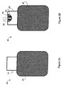
- FIG 2A there is shown a top view of a prior art USB plug 40 that is designed to be plugged into a standard USB socket, such as the prior art USB socket 10 of Figure 1A.
- the body 42 of plug 40 is attached to a standard USB connector housing 44 known in the art.
- FIG. 2B there is shown a top view of a selective plug 50 of the present invention.
- the body 42 is attached to a connector shell 52, typically made of metal.
- a recess 54 is included at the top-side (i.e. the flat side remote from the printed circuit board) of connector shell 52 to match protrusion 22 placed on the inward-facing surface at the broad side 25 of housing 21 that is remote from the printed circuit board 14 (of Figure 1B).
- Recess 54 is shaped to fit protrusion 22 of Figure 1B when USB plug 50 is plugged into socket 20 of Figure 1B.
- a standard male connector that is not equipped with such a recess can not be plugged into socket 20 of Figure 1B.
- recess 54 is located at the bottom-side (i.e. the flat side close to the printed circuit board) of connector shell 52 to match a protrusion similar to protrusion 22 but placed on the inward-facing surface at the broad side 26 of housing 21 that is closest to the printed circuit board 14 and conductor pins 16 (of Figure 1B).
- more than one recess can be located at either or both side of connector shell 52.
- plug 50 can be also plugged to any standard female connector (e.g. the USB socket 20 of Figure 1A).
- Conductor pins 56 implemented within connector shell 52 are marked with dotted lines to indicate that these pins, which are to contact conductors 16 of printed circuit board 14 (of Figure 1B), are located on the hidden bottom part of printed circuit board 55 (of Figure 2B).
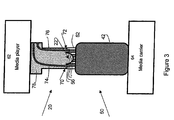
- FIG 3 there is shown the way in which plug 50 of Figure 2B is plugged into socket 20 of Figure 1B.
- Connector shell 52 is attached to the body 42 of plug 50.
- Conductor pins 56 implemented within connector shell 52 contact conductors 16 of printed circuit board 14 (see Figure 1B).
- Plug 50 (see Figure 2B) includes recess 54 for accommodating protrusion 22 of socket 50 (see Figure 1B).
- Two electric wires 74 and 76 are routed, insulated, through the volume of socket housing 78.
- a part of the metallic connector shell 52 contacts two conductive pads 70 and 72 and provides electric wires 74 and 76 an electrically conductive path between the two conductive pads 70 and 72.
- Such provision of an electrically conductive path between two conductive pads 70 and 72 is conditional on connecting an authorized plug only (e.g. plug. 50 of Figure 2B) to the socket 20 of Figure 1B.
- This requirement of a conductive path between the two conductive pads 70 and 72 5 protects against any attempt to remove or cut shell of socket 20 that may be made by users who wish to bypass the security feature of the embodiment.
- socket 20 as illustrated in Figure 3 is part of a device, such as a media player 62 for playing data such as music stored on digital media, and plug 50 is part of a device such as a media carrier 64 for storing the digital data.
- socket 20 is designed to selectively prevent from plugging an unauthorized prior art plug 40 into socket 20.
- Protrusion 22 is configured inside socket 20 so that no prior art plug 40, not even a prior art plug 40 configured according to the standard of socket 20, can properly be plugged into socket 20.
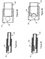
- FIG. 4B there is shown a schematic top view of the way in which the socket 20 is configured with protrusion 22 to prevent plugging the unauthorized prior art plug 40 into socket 20.
- Plug 50 embodying the present invention is plugged into socket 20 embodying the present invention.
- Plug 50 is equipped with recess 54 that accommodate protrusion 22 when plug 50 is plugged into socket 20.
- FIG. 4D there is shown a schematic top view of the way in which plug 50 is plugged into USB socket 20.
- plug and socket devices embodying the present invention are male and female Type A USB connecting devices respectively.
- modification of plugs and sockets that conform to other standards and protocols are possible within the scope of the invention, thus relating to any male and female connectors.
- the implementation of the selective socket device and the selective plug device embodying the present invention provides digital rights protection. While uploading of data can be made from the media player to any media carrier, only media carriers including the selective plug device of the present invention are configured to allow downloading digital information into such media player. This can be achieved by configuring a media player with the selective socket device and a media carrier with the selective plug device. Alternatively, this can be further achieved by connecting, by means of a cable, the media player to the selective socket device and by connecting the media carrier to the selective plug device.
- plug and “socket” is done herein for clarity of description.
- the difference between a plug and a socket is only in their relative posture when mating - the plug is typically brought to penetrate into the socket.
- a system embodying the present invention remains valid also if the operational features of the plug and the socket are switched (i.e. the connecting device of the media player operates as a plug and the connecting device of the media carrier operates as a socket), as long as the media player is connected to a connecting device having a restriction structure and the media carrier is connected to a connecting device having a respective accommodating structure.
Landscapes
- Engineering & Computer Science (AREA)
- Computer Hardware Design (AREA)
- Theoretical Computer Science (AREA)
- Computer Security & Cryptography (AREA)
- Software Systems (AREA)
- Physics & Mathematics (AREA)
- General Engineering & Computer Science (AREA)
- General Physics & Mathematics (AREA)
- Details Of Connecting Devices For Male And Female Coupling (AREA)
Applications Claiming Priority (2)
| Application Number | Priority Date | Filing Date | Title |
|---|---|---|---|
| US77415706P | 2006-02-17 | 2006-02-17 | |
| US11/495,627 US7402086B2 (en) | 2006-02-17 | 2006-07-31 | USB connecting system and method |
Publications (2)
| Publication Number | Publication Date |
|---|---|
| EP1821371A2 true EP1821371A2 (de) | 2007-08-22 |
| EP1821371A3 EP1821371A3 (de) | 2007-08-29 |
Family
ID=38084713
Family Applications (2)
| Application Number | Title | Priority Date | Filing Date |
|---|---|---|---|
| EP07250590A Withdrawn EP1821371A3 (de) | 2006-02-17 | 2007-02-14 | System und Verfahren zum Verbinden von USB-Steckern |
| EP07706148A Withdrawn EP1984987A1 (de) | 2006-02-17 | 2007-02-14 | Usb-verbindungssystem und verfahren |
Family Applications After (1)
| Application Number | Title | Priority Date | Filing Date |
|---|---|---|---|
| EP07706148A Withdrawn EP1984987A1 (de) | 2006-02-17 | 2007-02-14 | Usb-verbindungssystem und verfahren |
Country Status (6)
| Country | Link |
|---|---|
| US (1) | US7402086B2 (de) |
| EP (2) | EP1821371A3 (de) |
| JP (1) | JP2007220677A (de) |
| KR (1) | KR20070082890A (de) |
| TW (1) | TW200810272A (de) |
| WO (1) | WO2007093995A1 (de) |
Cited By (1)
| Publication number | Priority date | Publication date | Assignee | Title |
|---|---|---|---|---|
| WO2013117724A1 (en) * | 2012-02-09 | 2013-08-15 | Sanofi-Aventis Deutschland Gmbh | Micro plug and modified standard micro receptacle |
Families Citing this family (4)
| Publication number | Priority date | Publication date | Assignee | Title |
|---|---|---|---|---|
| US7627343B2 (en) * | 2003-04-25 | 2009-12-01 | Apple Inc. | Media player system |
| JP2010251319A (ja) | 2009-04-15 | 2010-11-04 | Chou Hsien Tsai | 双方向電気的連接が可能なソケット構造 |
| US20120041744A1 (en) * | 2010-07-28 | 2012-02-16 | Kantzes Christopher P | Handheld field maintenance tool with field device simulation capability |
| WO2016186615A1 (en) * | 2015-05-15 | 2016-11-24 | Hewlett-Packard Development Company,L. P. | Port protectors with adhesive agents |
Family Cites Families (14)
| Publication number | Priority date | Publication date | Assignee | Title |
|---|---|---|---|---|
| EP0108477A1 (de) * | 1982-09-21 | 1984-05-16 | The Whitaker Corporation | Kodierungssystem für Steckerfamilien |
| GB9306881D0 (en) * | 1993-04-01 | 1993-05-26 | Strix Ltd | Electrical coupling |
| US5370556A (en) * | 1993-09-20 | 1994-12-06 | The Whitaker Corporation | Keying system for electrical connectors |
| US6086430A (en) * | 1997-02-27 | 2000-07-11 | International Business Machines Corporation | Enhanced universal serial bus |
| JP2000208208A (ja) * | 1999-01-18 | 2000-07-28 | Sony Corp | コネクタ装置及びそれを用いた電子機器並びにプラグ |
| MY123388A (en) * | 1999-03-15 | 2006-05-31 | Sony Corp | Processing method and apparatus for encrypted data transfer |
| US6074256A (en) * | 1999-04-15 | 2000-06-13 | Lucent Technologies Inc. | High performance electrical connector assembly |
| US7182523B2 (en) * | 2004-12-29 | 2007-02-27 | Tyco Electronics Corporation | Connector and receptacle containing a physical security feature |
| TW549740U (en) * | 2002-07-26 | 2003-08-21 | Hon Hai Prec Ind Co Ltd | Electrical connector |
| DE20309812U1 (de) * | 2003-06-25 | 2003-12-04 | Friwo Gerätebau Gmbh | Steckverbindung für ein mobiles Endgerät |
| US6854984B1 (en) * | 2003-09-11 | 2005-02-15 | Super Talent Electronics, Inc. | Slim USB connector with spring-engaging depressions, stabilizing dividers and wider end rails for flash-memory drive |
| US6976885B2 (en) * | 2004-03-02 | 2005-12-20 | Mobility Electronics, Inc. | Keyed universal power tip and power source connectors |
| AU2005255683A1 (en) * | 2004-06-17 | 2005-12-29 | Walletex Microelectronics Ltd. | Improved connector and device for flexibly connectable computer systems |
| US7056149B1 (en) * | 2004-11-12 | 2006-06-06 | Comarco Wireless Technologies, Inc. | Key coded power adapter connectors |
-
2006
- 2006-07-31 US US11/495,627 patent/US7402086B2/en active Active
-
2007
- 2007-02-14 WO PCT/IL2007/000206 patent/WO2007093995A1/en not_active Ceased
- 2007-02-14 EP EP07250590A patent/EP1821371A3/de not_active Withdrawn
- 2007-02-14 EP EP07706148A patent/EP1984987A1/de not_active Withdrawn
- 2007-02-14 JP JP2007033388A patent/JP2007220677A/ja not_active Abandoned
- 2007-02-16 KR KR1020070016417A patent/KR20070082890A/ko not_active Ceased
- 2007-02-16 TW TW096105930A patent/TW200810272A/zh unknown
Cited By (2)
| Publication number | Priority date | Publication date | Assignee | Title |
|---|---|---|---|---|
| WO2013117724A1 (en) * | 2012-02-09 | 2013-08-15 | Sanofi-Aventis Deutschland Gmbh | Micro plug and modified standard micro receptacle |
| US9478914B2 (en) | 2012-02-09 | 2016-10-25 | Sanofi-Aventis Deutschland Gmbh | Micro plug and keyed micro receptacle |
Also Published As
| Publication number | Publication date |
|---|---|
| US7402086B2 (en) | 2008-07-22 |
| EP1984987A1 (de) | 2008-10-29 |
| JP2007220677A (ja) | 2007-08-30 |
| TW200810272A (en) | 2008-02-16 |
| EP1821371A3 (de) | 2007-08-29 |
| US20070197065A1 (en) | 2007-08-23 |
| WO2007093995A1 (en) | 2007-08-23 |
| KR20070082890A (ko) | 2007-08-22 |
Similar Documents
| Publication | Publication Date | Title |
|---|---|---|
| US8215983B2 (en) | Electronic device | |
| TWI553976B (zh) | 用於usb3之連接器插座及組裝用於usb3之連接器插座之方法 | |
| US20070197101A1 (en) | Super slim compact flash (cf) light universal serial bus (usb) device | |
| US20040043651A1 (en) | AC adapter connector assembly | |
| US7364463B1 (en) | Stacked connector assembly | |
| EP1821371A2 (de) | System und Verfahren zum Verbinden von USB-Steckern | |
| US6642614B1 (en) | Multi-functional memory chip connector | |
| CN100588049C (zh) | Sata连接器 | |
| JP2008225939A (ja) | Usbプラグ及び該usbプラグを備えたusb機器 | |
| US6902435B1 (en) | Electrical connector adapted for use with different electronic cards | |
| JP2003150912A (ja) | スマートカードアダプタ | |
| US6926559B1 (en) | Electrical connector adapted for use with different electronic cards | |
| US20150118918A1 (en) | Assembly of an electrical connector and a cable unit and electronic device including the assembly | |
| US6896527B1 (en) | Slim USB male connector with system grounding | |
| JP5829642B2 (ja) | 電子機器 | |
| CN101854006A (zh) | 电子设备组合及其连接器组合 | |
| CN100399635C (zh) | 连接器 | |
| JPH07235356A (ja) | 電気コネクタ | |
| EP3073582A1 (de) | Port-and-plug-systeme mit universellem seriellem bus (usb) | |
| US20080160791A1 (en) | Memory card with a slim USB connector | |
| US20040110408A1 (en) | Connector with changeable connecting manner | |
| CN209963383U (zh) | 具有内藏式锁定机构的连接器组及其插座连接器 | |
| CN2929987Y (zh) | Sata连接器 | |
| TWM532670U (zh) | 電連接器 | |
| KR200368523Y1 (ko) | 메모리 카드 휴대용 디스크 |
Legal Events
| Date | Code | Title | Description |
|---|---|---|---|
| PUAI | Public reference made under article 153(3) epc to a published international application that has entered the european phase |
Free format text: ORIGINAL CODE: 0009012 |
|
| PUAL | Search report despatched |
Free format text: ORIGINAL CODE: 0009013 |
|
| AK | Designated contracting states |
Kind code of ref document: A2 Designated state(s): AT BE BG CH CY CZ DE DK EE ES FI FR GB GR HU IE IS IT LI LT LU LV MC NL PL PT RO SE SI SK TR |
|
| AX | Request for extension of the european patent |
Extension state: AL BA HR MK YU |
|
| AK | Designated contracting states |
Kind code of ref document: A3 Designated state(s): AT BE BG CH CY CZ DE DK EE ES FI FR GB GR HU IE IS IT LI LT LU LV MC NL PL PT RO SE SI SK TR |
|
| AX | Request for extension of the european patent |
Extension state: AL BA HR MK YU |
|
| 17P | Request for examination filed |
Effective date: 20071024 |
|
| 17Q | First examination report despatched |
Effective date: 20071206 |
|
| AKX | Designation fees paid |
Designated state(s): AT BE BG CH CY CZ DE DK EE ES FI FR GB GR HU IE IS IT LI LT LU LV MC NL PL PT RO SE SI SK TR |
|
| STAA | Information on the status of an ep patent application or granted ep patent |
Free format text: STATUS: THE APPLICATION IS DEEMED TO BE WITHDRAWN |
|
| 18D | Application deemed to be withdrawn |
Effective date: 20090901 |