EP1821366B1 - Mechanical scanning antenna scanning a broad spatial range with reduced bulk - Google Patents
Mechanical scanning antenna scanning a broad spatial range with reduced bulk Download PDFInfo
- Publication number
- EP1821366B1 EP1821366B1 EP07101714A EP07101714A EP1821366B1 EP 1821366 B1 EP1821366 B1 EP 1821366B1 EP 07101714 A EP07101714 A EP 07101714A EP 07101714 A EP07101714 A EP 07101714A EP 1821366 B1 EP1821366 B1 EP 1821366B1
- Authority
- EP
- European Patent Office
- Prior art keywords
- stator
- rotor
- antenna
- output
- scanning
- Prior art date
- Legal status (The legal status is an assumption and is not a legal conclusion. Google has not performed a legal analysis and makes no representation as to the accuracy of the status listed.)
- Not-in-force
Links
Images
Classifications
-
- H—ELECTRICITY
- H01—ELECTRIC ELEMENTS
- H01Q—ANTENNAS, i.e. RADIO AERIALS
- H01Q3/00—Arrangements for changing or varying the orientation or the shape of the directional pattern of the waves radiated from an antenna or antenna system
- H01Q3/12—Arrangements for changing or varying the orientation or the shape of the directional pattern of the waves radiated from an antenna or antenna system using mechanical relative movement between primary active elements and secondary devices of antennas or antenna systems
- H01Q3/14—Arrangements for changing or varying the orientation or the shape of the directional pattern of the waves radiated from an antenna or antenna system using mechanical relative movement between primary active elements and secondary devices of antennas or antenna systems for varying the relative position of primary active element and a refracting or diffracting device
-
- H—ELECTRICITY
- H01—ELECTRIC ELEMENTS
- H01Q—ANTENNAS, i.e. RADIO AERIALS
- H01Q13/00—Waveguide horns or mouths; Slot antennas; Leaky-waveguide antennas; Equivalent structures causing radiation along the transmission path of a guided wave
- H01Q13/10—Resonant slot antennas
- H01Q13/12—Longitudinally slotted cylinder antennas; Equivalent structures
-
- H—ELECTRICITY
- H01—ELECTRIC ELEMENTS
- H01Q—ANTENNAS, i.e. RADIO AERIALS
- H01Q13/00—Waveguide horns or mouths; Slot antennas; Leaky-waveguide antennas; Equivalent structures causing radiation along the transmission path of a guided wave
- H01Q13/20—Non-resonant leaky-waveguide or transmission-line antennas; Equivalent structures causing radiation along the transmission path of a guided wave
- H01Q13/22—Longitudinal slot in boundary wall of waveguide or transmission line
-
- H—ELECTRICITY
- H01—ELECTRIC ELEMENTS
- H01Q—ANTENNAS, i.e. RADIO AERIALS
- H01Q19/00—Combinations of primary active antenna elements and units with secondary devices, e.g. with quasi-optical devices, for giving the antenna a desired directional characteristic
- H01Q19/06—Combinations of primary active antenna elements and units with secondary devices, e.g. with quasi-optical devices, for giving the antenna a desired directional characteristic using refracting or diffracting devices, e.g. lens
- H01Q19/062—Combinations of primary active antenna elements and units with secondary devices, e.g. with quasi-optical devices, for giving the antenna a desired directional characteristic using refracting or diffracting devices, e.g. lens for focusing
Definitions
- the present invention relates to a mechanical scanning antenna scanning a wide space domain and reduced space. It is particularly applicable for airborne radar applications subject to space constraints and aerodynamic performance.
- Radar detection is done within one or more transmit beams produced by the radar antenna.
- a beam covers a limited part of the space. The detection therefore requires scanning of a transmission beam to cover most of the space.
- a first mode is mechanical scanning. In this mode, the beam remains fixed with respect to the mechanical structure of the antenna. It is the antenna movements, in azimuth and / or in site which then generate the scanning of the emission beam.
- a second basic mode is electronic scanning. In this case, the antenna remains fixed and the scanning of the emission beam is generated electronically by playing on the phase shifts of radiating modules.
- a third mode can combine mechanical scanning and electronic scanning.
- An electronic scanning antenna has very good scanning performance, in particular with regard to scanning speed and agility but also the spatial amplitude of the scanning.
- a mechanical scanning antenna which does not always have the performance of an electronic scanning antenna, may be perfectly suitable for certain applications, particularly for economic aspects, where simplicity or low realization costs are required.
- the disadvantages of mechanical scanning are well known.
- the spatial amplitude of the scanning of the beam is limited by the movements of the antenna itself.
- the antenna can move only inside a sphere of space limiting the spatial scanning range of the emission beam of the antenna.
- the space required for the operation of the antenna in particular for performing its scanning movements in one or two planes, in fact its sphere of space itself, increases the overall bulk volume of the antenna. In fact, to obtain a sweep over a wide domain imposes a sphere of large size.
- the document US 3,018,479 discloses a beam scanning antenna which has a conical shaped stator having an input and an output and a conically shaped rotor rotating inside the stator, the space between the rotor and the waveguide stator.
- the focusing system is for example integrated in a radome.
- the stator comprises, for example upstream of the inlet and downstream of the outlet, a protuberance blocking the passage of the microwave wave.
- the rotor comprises, for example downstream of the inlet and upstream of the output of the diametral waveguide, a microwave trap blocking the passage of the microwave wave.
- the focusing system comprises a second focusing lens whose focus is located substantially at the entrance of the stator.
- the main advantages of the invention are that it makes it possible to reduce the space required for the operation of the antenna, that it makes it possible to obtain a strong misalignment of the antenna, that it avoids the use of rotating joints, that it makes it possible to obtain an antenna radome of aerodynamic shape and that it is economical.
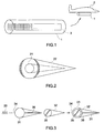
- the figure 1 shows by way of example the case of an antenna for SAR applications ("Synthetic Aperture Radar" in the English terminology).
- This antenna slots, is placed in a pod 1 integrated under a plane 2.
- the deflections of the antenna are limited by the pod defining a sphere of space.
- this sphere of space limits the scanning range of the antenna. Since the dimensions of a pod or radome inside which an antenna is placed can not be increased indefinitely, especially in airborne applications, it follows that the mechanical scanning of an antenna is systematically limited, more or more important depending on the case. In other words, the small volume of space available limits the misalignment of an antenna.
- the figure 2 illustrates in perspective view a mechanical scanning antenna according to the invention.
- the antenna comprises a Foster 21 system which is associated with a focusing system 22 allowing in particular the emission of a high directivity antenna lobe.
- the focusing system is for example a tapered focusing radome.
- the Foster 21 system provides mechanical misalignment of an antenna beam.
- a Foster system 21 is thus composed of two parts 31, 32.
- a first part is a stator 31 and a second part is a rotor 32.
- the rotor and the stator are both of conical shape, the rotor rotating inside. of the stator.
- the wave 33 to be transmitted first enters an input 34 of the stator 31, continues its way in the space between the stator and the rotor and then enters the inside of the rotor in a diametrical passage 35. diametrical waveguide inside the rotor. At the output of the rotor the wave continues its path between the stator and the rotor to an output 36 of the stator.
- the openings, at the inlet 34 and at the outlet 36, are made longitudinally along the entire length of the stator or in a portion.
- the diametral waveguide 35 is made in the rotor on the same length as the openings of the inlet and the outlet.
- the incoming wave 33 is out of phase with an electrical path as described later.
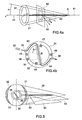
- the Figures 4a and 4b allows to describe the functioning of a Foster system.
- the figure 4a presents a perspective view of the stator and the rotor.
- the stator 31 of conical shape is fixed.
- the rotor 32 also conical in shape, rotates inside the stator.
- These two parts 31, 32 have a common axis of symmetry 41.
- the figure 4b presents a sectional view of the figure 4a in a plane 42 perpendicular to the axis of symmetry 41 of the stator. Note the position of this plane 42 along the axis of symmetry 41.
- the wave 33 enters the stator and then into the rotor as indicated above.
- the input 34 and the output 36 of the stator are for example symmetrical with respect to the axis of symmetry 41 of the stator.
- the passage of the wave 33 through the rotor is inside a path 35 hollowed out diametrically in the rotor.
- this diametrical path 35 makes an angle ⁇ r with the entry point 34 of the wave in the stator.
- This angle ⁇ r is in fact the angle of rotation of the stator with respect to the stator having its origin at the point of entry 34 of the wave 33 in the stator.
- the angle ⁇ r is a function of time.
- the wave 33 enters the stator at the input 34 then enters the diametrical path 35 and finally leaves the stator at the output 36. path traveled within the system formed by the stator and the rotor is thus composed of three portions.
- a first portion 43 located between the stator and the rotor, begins at the point of entry 34 to the point of entry into the rotor.
- the distance traveled in this first portion 43 is R (z) ⁇ r .
- R (z) is the radius of the path traveled, it depends on the position z of the plane 42 along the axis of symmetry 41 due to the conical shape of the stator and the rotor. The origin of the positions z on the axis of symmetry can for example be taken at the top of the cone S.
- the second path portion consists of the entire transverse path within the rotor. The distance traveled in this second portion is substantially equal to 2R (z).
- the third portion 44 is symmetrically opposed to the first portion 43, it goes from the output of the rotor to the output point 36 of the stator. It is therefore equal to R (z) ⁇ r .
- the interior of the stator 31 and the outside of the rotor 32 are for example covered with a metal layer so that the space between the stator and the rotor can guide the incoming microwave wave 33.
- the width of this space can be defined according to the wavelength.
- the passage 35 provided inside the rotor 32 forms a waveguide. Its inner faces are for example covered with a metal layer, the width of this passage depending in particular on the wavelength.
- a protrusion 45 projecting inside the stator is located near the inlet 34 to block the passage of the incoming wave in one direction.
- the protuberance 45 extends as far as possible from the surface of the rotor. It therefore prevents the incoming wave from following the wrong direction by forcing it to follow the intended path 43.
- a second protrusion 46 is, for example, provided next to the previous 45.
- a microwave trap 47 is placed downstream of the rotor inlet, and close to the latter.
- This trap 47 is, for example, formed of a microwave short circuit at ⁇ / 4.
- This trap 47 is placed on the surface of the rotor but on the inside so as not to come into contact with a protuberance 45, 46 of the stator during the rotation of the rotor.
- Another microwave trap 48 is diametrically opposed to the previous 47 to force the microwave to follow the path 44 to the output 36 of the stator.
- the stator has another protrusion 49 diametrically opposed to the first 45 to force the microwave to continue to the output 36.
- the protuberances 45, 49 could be replaced by microwave traps.
- the incoming wave is out of phase with the electrical path ⁇ (z) on the portions 43, 35, 44.
- the phase shift is therefore a function of the angular position of the rotor and the distance z with respect to the tip S of the cone.
- the relation (6) gives the angle of misalignment of the microwave beam at the output 36 of the stator.
- This angle ⁇ p is the angle made by the direction 50 of the beam with the perpendicular. It is a function of the rotation angle ⁇ r of the rotor, itself a function of time. Rotation of the rotor thus induces a misalignment of the output microwave beam 36 of the stator, the misalignment angle being a function of the rotation of the rotor according to relation (6).
- the misalignment angle is independent of the microwave wavelength ⁇ .
- the microwave beam is very directional, due in particular to the small opening width of the stator at the outlet 36.
- the figure 5 shows an embodiment of an antenna according to the invention where the assembly consisting of the stator and the rotor of the Figures 4a and 4b is equipped with a focusing system 22.
- the focusing system comprises at least one focusing lens 51.
- the focus of the lens 51 is substantially at the output 36 of the stator. In this way, the lens 51 makes it possible to focus the microwave beam and to obtain a very directional microwave beam.
- This beam forms the antenna beam 53 of an antenna according to the invention.
- This beam sweeps the space according to the misalignment angle ⁇ p itself a function of the rotation ⁇ r of the rotor.
- the focusing system may be completed by a second lens 52, for example symmetrical with respect to the first. This second lens is useful when the input 34 of the stator becomes the output of the microwave wave.
- a focusing lens 51, 52 is for example of type D glass to which is added a binder of polyester type.
- Unrepresented waveguides are provided to guide the microwave to the input of the stator.
- the focusing system 22 may also act as a radome. Its shape is imposed by the shape of the stator on which the lenses must focus. This results in a form of substantially conical radome so very aerodynamic.
- a mechanical antenna beam scan according to the invention although of mechanical type, does not require rotating joints.
- no space sphere is necessary. This solution is, therefore, well suited for applications requiring high misalignments, for example, of ⁇ 120 °.
Abstract
Description
La présente invention concerne une antenne à balayage mécanique balayant un large domaine spatial et à encombrement réduit. Elle s'applique notamment pour des applications radar aéroportées soumises à des contraintes d'encombrement et de performances aérodynamiques.The present invention relates to a mechanical scanning antenna scanning a wide space domain and reduced space. It is particularly applicable for airborne radar applications subject to space constraints and aerodynamic performance.
Une détection radar se fait à l'intérieur d'un ou plusieurs faisceaux d'émission produits par l'antenne du radar. Un faisceau couvre une partie limitée de l'espace. La détection impose donc d'effectuer un balayage d'un faisceau d'émission en vue de couvrir la plus grande partie de l'espace.
Il existe deux modes de base pour produire un balayage de faisceaux d'émission.
Un premier mode est le balayage mécanique. Dans ce mode, le faisceau reste fixe par rapport à la structure mécanique de l'antenne. Ce sont les mouvements d'antenne, en azimut et/ou en site qui génèrent alors le balayage du faisceau d'émission.
Un deuxième mode de base est le balayage électronique. Dans ce cas, l'antenne reste fixe et le balayage du faisceau d'émission est généré électroniquement en jouant de façon sur les déphasages de modules rayonnant. Un troisième mode peut combiner le balayage mécanique et le balayage électronique.
Une antenne à balayage électronique présente de très bonnes performances de balayage, en particulier en ce qui concerne la rapidité et l'agilité de balayage mais aussi l'amplitude spatiale du balayage. Par ailleurs, son fonctionnement ne nécessite qu'un encombrement relativement réduit puisqu'il n'est pas nécessaire de réserver un espace aux mouvements de l'antenne. Ce mode de balayage présente néanmoins certains inconvénient, notamment en ce qui concerne les coûts et la complexité de réalisation.
Une antenne à balayage mécanique, qui ne possède pas toujours les performances d'une antenne à balayage électronique, peut parfaitement convenir à certaines applications, en particulier pour des aspects économiques, lorsque la simplicité ou de faibles coûts de réalisation sont exigés. Les inconvénients du balayage mécanique sont bien connus. En particulier, l'amplitude spatiale du balayage du faisceau est limitée par les mouvements de l'antenne elle-même. Dans une configuration mécanique donnée, l'antenne ne peut se mouvoir qu'à l'intérieur d'une sphère d'encombrement limitant le domaine spatial de balayage du faisceau d'émission de l'antenne. De plus l'encombrement nécessaire au fonctionnement de l'antenne notamment pour effectuer ses mouvements de balayage dans un ou deux plans, en fait sa sphère d'encombrement elle-même, augmente le volume d'encombrement général de l'antenne. En fait, pour obtenir un balayage sur un large domaine impose une sphère d'encombrement importante.Radar detection is done within one or more transmit beams produced by the radar antenna. A beam covers a limited part of the space. The detection therefore requires scanning of a transmission beam to cover most of the space.
There are two basic modes for producing a transmit beam scan.
A first mode is mechanical scanning. In this mode, the beam remains fixed with respect to the mechanical structure of the antenna. It is the antenna movements, in azimuth and / or in site which then generate the scanning of the emission beam.
A second basic mode is electronic scanning. In this case, the antenna remains fixed and the scanning of the emission beam is generated electronically by playing on the phase shifts of radiating modules. A third mode can combine mechanical scanning and electronic scanning.
An electronic scanning antenna has very good scanning performance, in particular with regard to scanning speed and agility but also the spatial amplitude of the scanning. Moreover, its operation requires only a relatively small footprint since it is not necessary to reserve space for the movements of the antenna. This scanning mode nevertheless has certain drawbacks, especially as regards the costs and the complexity of implementation.
A mechanical scanning antenna, which does not always have the performance of an electronic scanning antenna, may be perfectly suitable for certain applications, particularly for economic aspects, where simplicity or low realization costs are required. The disadvantages of mechanical scanning are well known. In particular, the spatial amplitude of the scanning of the beam is limited by the movements of the antenna itself. In a mechanical configuration given, the antenna can move only inside a sphere of space limiting the spatial scanning range of the emission beam of the antenna. In addition, the space required for the operation of the antenna, in particular for performing its scanning movements in one or two planes, in fact its sphere of space itself, increases the overall bulk volume of the antenna. In fact, to obtain a sweep over a wide domain imposes a sphere of large size.
Le document
Un but de l'invention est de pallier cet inconvénient, en particulier en permettant la réalisation d'une antenne à balayage mécanique balayant un large domaine spatial. A cet effet, l'invention a pour objet une antenne à balayage de faisceau comportant au moins :
- un stator de forme conique comportant une entrée et une sortie ;
- un rotor de forme conique tournant à l'intérieur du stator, l'espace entre le rotor et le stator formant guide d'onde, le rotor comportant un guide d'onde diamétral, une onde hyperfréquence à émettre étant guidée de l'entrée jusqu'à la sortie via le guide diamétral du rotor ;
- un système focalisateur comportant au moins une lentille focalisante dont le foyer est situé sensiblement à la sortie du stator.
- a conical shaped stator having an inlet and an outlet;
- a conical rotor rotating inside the stator, the space between the rotor and the waveguide stator, the rotor comprising a diametrical waveguide, a microwave wave to be emitted being guided from the input to the at the outlet via the diametral guide of the rotor;
- a focusing system comprising at least one focusing lens whose focus is located substantially at the output of the stator.
Le système focalisateur est par exemple intégré dans un radôme.
Le stator comporte par exemple en amont de l'entrée et en aval de la sortie une protubérance bloquant le passage de l'onde hyperfréquence.
Le rotor comporte par exemple en aval de l'entrée et en amont de la sortie du guide d'onde diamétral un piège hyperfréquence bloquant le passage de l'onde hyperfréquence.
Le système focalisateur comporte une deuxième lentille focalisante dont le foyer est situé sensiblement à l'entrée du stator.The focusing system is for example integrated in a radome.
The stator comprises, for example upstream of the inlet and downstream of the outlet, a protuberance blocking the passage of the microwave wave.
The rotor comprises, for example downstream of the inlet and upstream of the output of the diametral waveguide, a microwave trap blocking the passage of the microwave wave.
The focusing system comprises a second focusing lens whose focus is located substantially at the entrance of the stator.
L'invention a pour principaux avantages qu'elle permet de réduire l'encombrement nécessaire au fonctionnement de l'antenne, qu'elle permet d'obtenir un fort dépointage d'antenne, qu'elle évite l'utilisation de joints tournants, qu'elle permet d'obtenir un radôme d'antenne de forme aérodynamique et qu'elle est économique.The main advantages of the invention are that it makes it possible to reduce the space required for the operation of the antenna, that it makes it possible to obtain a strong misalignment of the antenna, that it avoids the use of rotating joints, that it makes it possible to obtain an antenna radome of aerodynamic shape and that it is economical.
D'autres caractéristiques et avantages de l'invention apparaîtront à l'aide de la description qui suit faite en regard de dessins annexés qui représentent :
- la
figure 1 , un exemple d'antenne selon l'art antérieur nécessitant une sphère d'encombrement ; - la
figure 2 , une illustration d'un système de Foster comportant d'un stator et d'un rotor et un système focalisateur formant une antenne selon l'invention ; - la
figure 3 , les composantes d'un système de Foster ; - les
figures 4a et 4b , une illustration du fonctionnement d'un système de Foster tel qu'utilisé dans une antenne selon l'invention ; - la
figure 5 , un exemple de réalisation d'une antenne selon l'invention.
- the
figure 1 an example of an antenna according to the prior art requiring a sphere of space; - the
figure 2 , an illustration of a Foster system comprising a stator and a rotor and a focusing system forming an antenna according to the invention; - the
figure 3 , the components of a Foster system; - the
Figures 4a and 4b an illustration of the operation of a Foster system as used in an antenna according to the invention; - the
figure 5 , an exemplary embodiment of an antenna according to the invention.
La
La
La
Les ouvertures, au niveau de l'entrée 34 et au niveau de la sortie 36, sont réalisées longitudinalement sur toute la longueur du stator ou selon une portion. Le guide d'onde diamétral 35 est réalisé dans le rotor sur la même longueur que les ouvertures de l'entrée et de la sortie.
L'onde entrante 33 est déphasée avec un chemin électrique comme décrit par la suite.The
The openings, at the
The
Les
La
L'onde 33 entre dans le stator au niveau de l'entrée 34 puis pénètre dans le chemin diamétral 35 et enfin sort du stator au niveau de la sortie 36. Le chemin parcouru à l'intérieur du système formé par le stator et le rotor est donc composé de trois portions. Une première portion 43, située entre le stator et le rotor, débute au point d'entrée 34 jusqu'au point d'entrée dans le rotor. La distance parcourue dans cette première portion 43 est R(z)θr. R(z) est le rayon du chemin parcouru, il dépend de la position z du plan 42 le long de l'axe de symétrie 41 en raison de la forme conique du stator et du rotor. L'origine des positions z sur l'axe de symétrie peut par exemple être prise au sommet du cône S.
La deuxième portion de chemin est constituée de la totalité du chemin transversale 35 à l'intérieur du rotor. La distance parcourue dans cette deuxième portion est sensiblement égale à 2R(z). Enfin, la troisième portion 44 est symétriquement opposée à la première portion 43, elle va de la sortie du rotor jusqu'au point de sortie 36 du stator. Elle est donc égale à R(z)θr. Ainsi, au niveau d'un point z de l'axe de symétrie 41 du stator, le chemin électrique δ(z) parcouru par l'onde entrante 33 est donné par la relation suivante : ![]()
θ r étant exprimé en radians dans cette relation (1).The
The
The
The second path portion consists of the entire transverse path within the rotor. The distance traveled in this second portion is substantially equal to 2R (z). Finally, the ![]()
θ r being expressed in radians in this relation (1).
L'intérieur du stator 31 et l'extérieur du rotor 32 sont par exemple recouverts d'une couche métallique de façon à ce que l'espace compris entre le stator et le rotor puisse guider l'onde hyperfréquence entrante 33. En particulier la largeur de cet espace peut être définie en fonction de la longueur d'onde. De même le passage 35 prévu à l'intérieur du rotor 32 forme un guide d'onde. Ses faces intérieures sont par exemple recouvertes d'une couche métallique, la largeur de ce passage dépendant notamment de la longueur d'onde.
Une protubérance 45 faisant saillie à l'intérieur du stator est située à proximité de l'entrée 34 pour bloquer le passage de l'onde entrante dans une direction. A cet effet la protubérance 45 s'étend le plus possible de la surface du rotor. Elle empêche donc l'onde entrante de suivre la mauvaise direction en l'obligeant à suivre le chemin 43 prévu. Pour renforcer le blocage du passage une deuxième protubérance 46 est, par exemple, prévu à côté de la précédente 45.The interior of the
A
Après avoir suivi le chemin 43 à l'intérieur du stator l'onde hyperfréquence doit ensuite entrer dans le chemin diamétral 35 du rotor. Pour empêcher l'onde de continuer plus loin sa course à l'intérieur du stator, un piège hyperfréquence 47 est placé en aval de l'entrée du rotor, et à proximité de cette dernière. Ce piège 47 est, par exemple, formé d'un court-circuit hyperfréquence à λ/4. Ce piège 47 est placé à la surface du rotor mais à l'intérieur pour ne pas entrer en contact avec une protubérance 45, 46 du stator lors de la rotation du rotor. Un autre piège hyperfréquence 48, par exemple de même structure, est diamétralement opposé au précédent 47 pour forcer l'onde hyperfréquence à suivre le chemin 44 vers la sortie 36 du stator. Le stator comporte une autre protubérance 49 diamétralement opposée à la première 45 pour forcer l'onde hyperfréquence à continuer vers la sortie 36. Les protubérances 45, 49 pourraient être remplacées par des pièges hyperfréquence.After following the
L'onde entrante est déphasée avec le chemin électrique δ(z) sur les portions 43, 35, 44. Le déphasage est donc fonction de la position angulaire du rotor et de la distance z par rapport à la pointe S du cône.
Le déphasage ϕ(z), fonction de la position z le long de l'axe de symétrie 41 est donné par la relation suivante : ![]()
où λ est la longueur de l'onde entrante 33.
En référence aux relations (1) et (2), le déphasage peut encore s'écrire : ![]()
Si α représente le demi-angle au sommet du cône, la relation entre le rayon R(z) en un point de l'axe de symétrie 41 du stator et la distance z de ce point au sommet est la suivante : ![]()
L'angle de dépointage θp de l'onde en regard d'un point z de l'axe 41 vérifie la relation suivante : 
Il en résulte que : ![]()
The phase shift φ (z), a function of the position z along the axis of ![]()
where λ is the length of the
With reference to relations (1) and (2), the phase difference can still be written: ![]()
If α represents the half-angle at the apex of the cone, the relationship between the radius R (z) at a point of the axis of ![]()
The misalignment angle θ p of the wave opposite a point z of the
It follows that : ![]()
La relation (6) donne l'angle de dépointage du faisceau hyperfréquence à la sortie 36 du stator. Cet angle θp est l'angle que fait la direction 50 du faisceau avec la perpendiculaire. Il est fonction de l'angle de rotation θr du rotor, lui-même fonction du temps. La rotation du rotor induit donc un dépointage du faisceau hyperfréquence en sortie 36 du stator, l'angle de dépointage étant fonction de la rotation du rotor selon la relation (6). L'angle de dépointage est indépendant de la longueur d'onde hyperfréquence λ. En sortie 36 du stator, le faisceau hyperfréquence est très peu directive, du fait notamment de la faible largeur d'ouverture du stator au niveau de la sortie 36.The relation (6) gives the angle of misalignment of the microwave beam at the
La
Le système focalisateur peut être complété par une deuxième lentille 52, par exemple symétrique par rapport à la première. Cette deuxième lentille est utile lorsque l'entrée 34 du stator devient la sortie de l'onde hyperfréquence.
Une lentille focalisante 51, 52 est par exemple en verre de type D auquel est ajouté un liant de type polyester.The
The focusing system may be completed by a
A focusing
Des guides d'onde non représentés sont prévus pour guider l'onde hyperfréquence jusqu'à l'entrée du stator.
Le système focalisateur 22 peut, par ailleurs, faire office de radôme. Sa forme est imposée par la forme du stator sur lequel les lentilles doivent se focaliser. Il en résulte une forme de radôme sensiblement conique donc très aérodynamique.Unrepresented waveguides are provided to guide the microwave to the input of the stator.
The focusing
Avantageusement, un balayage mécanique de faisceau d'antenne selon l'invention, bien que de type mécanique, ne nécessite pas de joints tournants.
Dans la solution proposée par une antenne selon l'invention, aucune sphère d'encombrement est nécessaire. Cette solution est, par conséquent, bien adaptée pour des applications nécessitant de forts dépointages, par exemple, de ± 120°.Advantageously, a mechanical antenna beam scan according to the invention, although of mechanical type, does not require rotating joints.
In the solution proposed by an antenna according to the invention, no space sphere is necessary. This solution is, therefore, well suited for applications requiring high misalignments, for example, of ± 120 °.
Claims (5)
- Beam-scanning antenna, the antenna comprising at least:- a stator (31) of conical shape comprising longitudinally over its length an input (34) and an output (36);- a rotor (32) of conical shape rotating inside the stator (31), the space between the rotor and the stator forming a waveguide, characterized in that the rotor comprises a diametral waveguide (35), a microwave (33) to be emitted being guided from the input (34) to the output (36) via the diametral guide of the rotor; and- a focusing system (22) comprising at least one focusing lens (51) whose focus is situated substantially at the output (36) of the stator.
- Antenna according to Claim 1, characterized in that the focusing system (22) is integrated into a radome.
- Antenna according to any one of the preceding claims, characterized in that the stator (31) comprises upstream of the input (34) and downstream of the output (36) a protuberance (45, 49) blocking the passage of the microwave (33).
- Antenna according to any one of the preceding claims, characterized in that the rotor (32) comprises downstream of the input and upstream of the output of the diametral waveguide (35) a microwave trap (47, 48) blocking the passage of the microwave (33).
- Antenna according to any one of the preceding claims, characterized in that the focusing system (22) comprises a second focusing lens (52) whose focus is situated substantially at the input (34) of the stator.
Applications Claiming Priority (1)
| Application Number | Priority Date | Filing Date | Title |
|---|---|---|---|
| FR0601325A FR2897475B1 (en) | 2006-02-15 | 2006-02-15 | MECHANICAL SCANNING ANTENNA SCANNING A WIDE SPATIAL DOMAIN WITH REDUCED DIMENSIONS |
Publications (2)
| Publication Number | Publication Date |
|---|---|
| EP1821366A1 EP1821366A1 (en) | 2007-08-22 |
| EP1821366B1 true EP1821366B1 (en) | 2008-12-10 |
Family
ID=36790949
Family Applications (1)
| Application Number | Title | Priority Date | Filing Date |
|---|---|---|---|
| EP07101714A Not-in-force EP1821366B1 (en) | 2006-02-15 | 2007-02-05 | Mechanical scanning antenna scanning a broad spatial range with reduced bulk |
Country Status (5)
| Country | Link |
|---|---|
| EP (1) | EP1821366B1 (en) |
| AT (1) | ATE417383T1 (en) |
| DE (1) | DE602007000328D1 (en) |
| ES (1) | ES2319579T3 (en) |
| FR (1) | FR2897475B1 (en) |
Family Cites Families (3)
| Publication number | Priority date | Publication date | Assignee | Title |
|---|---|---|---|---|
| US2670436A (en) * | 1950-05-03 | 1954-02-23 | Allen S Dunbar | Helical slot scanner |
| US3018479A (en) * | 1959-02-02 | 1962-01-23 | Hughes Aircraft Co | Scanning antenna |
| FR1320855A (en) * | 1962-01-31 | 1963-03-15 | Csf | Radiation program antenna |
-
2006
- 2006-02-15 FR FR0601325A patent/FR2897475B1/en not_active Expired - Fee Related
-
2007
- 2007-02-05 EP EP07101714A patent/EP1821366B1/en not_active Not-in-force
- 2007-02-05 DE DE602007000328T patent/DE602007000328D1/en active Active
- 2007-02-05 AT AT07101714T patent/ATE417383T1/en not_active IP Right Cessation
- 2007-02-05 ES ES07101714T patent/ES2319579T3/en active Active
Also Published As
| Publication number | Publication date |
|---|---|
| FR2897475B1 (en) | 2008-04-18 |
| ES2319579T3 (en) | 2009-05-08 |
| FR2897475A1 (en) | 2007-08-17 |
| EP1821366A1 (en) | 2007-08-22 |
| ATE417383T1 (en) | 2008-12-15 |
| DE602007000328D1 (en) | 2009-01-22 |
Similar Documents
| Publication | Publication Date | Title |
|---|---|---|
| EP2081258B1 (en) | Secondary reflector of an antenna with double reflector | |
| EP2264832B1 (en) | Secondary reflector for a double reflector antenna | |
| FR2886773A1 (en) | Antenna e.g. airborne antenna, for airborne weather radar, has radiating waveguide divided into three sections, where central section of radiating wave guide is crossed with central section of vertical component stack of feed waveguide | |
| EP2130266B1 (en) | Antenna with resonator having a filtering coating and system including such antenna | |
| EP3086409B1 (en) | Structural antenna module including elementary radiating sources with individual orientation, radiating panel, radiating network and multibeam antenna comprising at least one such module | |
| WO2016207787A1 (en) | Dual-reflector microwave antenna | |
| EP2658032B1 (en) | Corrugated horn antenna | |
| EP1821366B1 (en) | Mechanical scanning antenna scanning a broad spatial range with reduced bulk | |
| EP0014605B1 (en) | Reverse cassegrain antenna for multipurpose radar | |
| FR2886771A1 (en) | Airborne weather radar antenna for e.g. meteorological phenomenon detection, has feed waveguide connected by coupling slots to radiating waveguides, where antenna beam pointing angle is varied by varying frequency of wave of feed waveguide | |
| FR2814614A1 (en) | DIVERGENT DOME LENS FOR MICROWAVE WAVES AND ANTENNA COMPRISING SUCH A LENS | |
| EP0021866B1 (en) | Device for reducing jamming signals with a rotating linear polarization and use thereof in a radar | |
| EP0061965B1 (en) | Antenna with a device for controlling the linear-polarization direction | |
| FR2594260A1 (en) | HYPERFREQUENCY PRIMARY SOURCE FOR CONCEALED SCANNING ANTENNA AND INCORPORATING ANTENNA. | |
| EP3220181B1 (en) | Hybrid optical system with reduced size for imaging array antenna | |
| FR3000289A1 (en) | OSCILLATING VIRTUAL CATHODE MICROWAVE GENERATOR WITH OPEN REFLECTORS | |
| EP0109322A1 (en) | Double reflector antenna for a tracking radar improving the target acquisition capability | |
| FR2767971A1 (en) | Lens antenna for motor vehicle | |
| EP0897201A1 (en) | Cylindrical reflector with sliding radiating elements | |
| FR2943466A1 (en) | Radiating element i.e. single pulse bipolarization radiating element, for e.g. Cassegrain reflector antenna of radar, has polarization filters set along direction parallel to dipole branches placed above plane of openings of waveguides | |
| EP0161127B1 (en) | Plane antenna with fast mechanical scan | |
| WO2019238643A1 (en) | Beam-forming mispointing system | |
| EP4148902A1 (en) | Electromagnetic system with angular deviation of the main dispersion lobe of an antenna. | |
| FR2783974A1 (en) | METHOD FOR ENLARGING THE RADIATION DIAGRAM OF AN ANTENNA, AND ANTENNA IMPLEMENTING THE SAME | |
| FR2738401A1 (en) | Wide angle antenna network e.g. for radar, telecommunications |
Legal Events
| Date | Code | Title | Description |
|---|---|---|---|
| PUAI | Public reference made under article 153(3) epc to a published international application that has entered the european phase |
Free format text: ORIGINAL CODE: 0009012 |
|
| AK | Designated contracting states |
Kind code of ref document: A1 Designated state(s): AT BE BG CH CY CZ DE DK EE ES FI FR GB GR HU IE IS IT LI LT LU LV MC NL PL PT RO SE SI SK TR |
|
| AX | Request for extension of the european patent |
Extension state: AL BA HR MK YU |
|
| 17P | Request for examination filed |
Effective date: 20080222 |
|
| AKX | Designation fees paid |
Designated state(s): AT BE BG CH CY CZ DE DK EE ES FI FR GB GR HU IE IS IT LI LT LU LV MC NL PL PT RO SE SI SK TR |
|
| GRAP | Despatch of communication of intention to grant a patent |
Free format text: ORIGINAL CODE: EPIDOSNIGR1 |
|
| GRAS | Grant fee paid |
Free format text: ORIGINAL CODE: EPIDOSNIGR3 |
|
| GRAA | (expected) grant |
Free format text: ORIGINAL CODE: 0009210 |
|
| AK | Designated contracting states |
Kind code of ref document: B1 Designated state(s): AT BE BG CH CY CZ DE DK EE ES FI FR GB GR HU IE IS IT LI LT LU LV MC NL PL PT RO SE SI SK TR |
|
| REG | Reference to a national code |
Ref country code: GB Ref legal event code: FG4D Free format text: NOT ENGLISH |
|
| REG | Reference to a national code |
Ref country code: CH Ref legal event code: EP |
|
| REG | Reference to a national code |
Ref country code: IE Ref legal event code: FG4D Free format text: LANGUAGE OF EP DOCUMENT: FRENCH |
|
| REF | Corresponds to: |
Ref document number: 602007000328 Country of ref document: DE Date of ref document: 20090122 Kind code of ref document: P |
|
| REG | Reference to a national code |
Ref country code: SE Ref legal event code: TRGR |
|
| PG25 | Lapsed in a contracting state [announced via postgrant information from national office to epo] |
Ref country code: LT Free format text: LAPSE BECAUSE OF FAILURE TO SUBMIT A TRANSLATION OF THE DESCRIPTION OR TO PAY THE FEE WITHIN THE PRESCRIBED TIME-LIMIT Effective date: 20081210 |
|
| REG | Reference to a national code |
Ref country code: ES Ref legal event code: FG2A Ref document number: 2319579 Country of ref document: ES Kind code of ref document: T3 |
|
| PG25 | Lapsed in a contracting state [announced via postgrant information from national office to epo] |
Ref country code: NL Free format text: LAPSE BECAUSE OF FAILURE TO SUBMIT A TRANSLATION OF THE DESCRIPTION OR TO PAY THE FEE WITHIN THE PRESCRIBED TIME-LIMIT Effective date: 20081210 Ref country code: PL Free format text: LAPSE BECAUSE OF FAILURE TO SUBMIT A TRANSLATION OF THE DESCRIPTION OR TO PAY THE FEE WITHIN THE PRESCRIBED TIME-LIMIT Effective date: 20081210 Ref country code: LV Free format text: LAPSE BECAUSE OF FAILURE TO SUBMIT A TRANSLATION OF THE DESCRIPTION OR TO PAY THE FEE WITHIN THE PRESCRIBED TIME-LIMIT Effective date: 20081210 Ref country code: FI Free format text: LAPSE BECAUSE OF FAILURE TO SUBMIT A TRANSLATION OF THE DESCRIPTION OR TO PAY THE FEE WITHIN THE PRESCRIBED TIME-LIMIT Effective date: 20081210 Ref country code: SI Free format text: LAPSE BECAUSE OF FAILURE TO SUBMIT A TRANSLATION OF THE DESCRIPTION OR TO PAY THE FEE WITHIN THE PRESCRIBED TIME-LIMIT Effective date: 20081210 |
|
| NLV1 | Nl: lapsed or annulled due to failure to fulfill the requirements of art. 29p and 29m of the patents act | ||
| REG | Reference to a national code |
Ref country code: IE Ref legal event code: FD4D |
|
| PG25 | Lapsed in a contracting state [announced via postgrant information from national office to epo] |
Ref country code: IE Free format text: LAPSE BECAUSE OF FAILURE TO SUBMIT A TRANSLATION OF THE DESCRIPTION OR TO PAY THE FEE WITHIN THE PRESCRIBED TIME-LIMIT Effective date: 20081210 Ref country code: RO Free format text: LAPSE BECAUSE OF FAILURE TO SUBMIT A TRANSLATION OF THE DESCRIPTION OR TO PAY THE FEE WITHIN THE PRESCRIBED TIME-LIMIT Effective date: 20081210 Ref country code: BG Free format text: LAPSE BECAUSE OF FAILURE TO SUBMIT A TRANSLATION OF THE DESCRIPTION OR TO PAY THE FEE WITHIN THE PRESCRIBED TIME-LIMIT Effective date: 20090310 Ref country code: EE Free format text: LAPSE BECAUSE OF FAILURE TO SUBMIT A TRANSLATION OF THE DESCRIPTION OR TO PAY THE FEE WITHIN THE PRESCRIBED TIME-LIMIT Effective date: 20081210 |
|
| BERE | Be: lapsed |
Owner name: THALES Effective date: 20090228 |
|
| PG25 | Lapsed in a contracting state [announced via postgrant information from national office to epo] |
Ref country code: IS Free format text: LAPSE BECAUSE OF FAILURE TO SUBMIT A TRANSLATION OF THE DESCRIPTION OR TO PAY THE FEE WITHIN THE PRESCRIBED TIME-LIMIT Effective date: 20090410 Ref country code: PT Free format text: LAPSE BECAUSE OF FAILURE TO SUBMIT A TRANSLATION OF THE DESCRIPTION OR TO PAY THE FEE WITHIN THE PRESCRIBED TIME-LIMIT Effective date: 20090511 Ref country code: AT Free format text: LAPSE BECAUSE OF FAILURE TO SUBMIT A TRANSLATION OF THE DESCRIPTION OR TO PAY THE FEE WITHIN THE PRESCRIBED TIME-LIMIT Effective date: 20081210 Ref country code: CZ Free format text: LAPSE BECAUSE OF FAILURE TO SUBMIT A TRANSLATION OF THE DESCRIPTION OR TO PAY THE FEE WITHIN THE PRESCRIBED TIME-LIMIT Effective date: 20081210 |
|
| PG25 | Lapsed in a contracting state [announced via postgrant information from national office to epo] |
Ref country code: SK Free format text: LAPSE BECAUSE OF FAILURE TO SUBMIT A TRANSLATION OF THE DESCRIPTION OR TO PAY THE FEE WITHIN THE PRESCRIBED TIME-LIMIT Effective date: 20081210 Ref country code: MC Free format text: LAPSE BECAUSE OF NON-PAYMENT OF DUE FEES Effective date: 20090228 |
|
| PLBE | No opposition filed within time limit |
Free format text: ORIGINAL CODE: 0009261 |
|
| STAA | Information on the status of an ep patent application or granted ep patent |
Free format text: STATUS: NO OPPOSITION FILED WITHIN TIME LIMIT |
|
| PG25 | Lapsed in a contracting state [announced via postgrant information from national office to epo] |
Ref country code: DK Free format text: LAPSE BECAUSE OF FAILURE TO SUBMIT A TRANSLATION OF THE DESCRIPTION OR TO PAY THE FEE WITHIN THE PRESCRIBED TIME-LIMIT Effective date: 20081210 |
|
| 26N | No opposition filed |
Effective date: 20090911 |
|
| REG | Reference to a national code |
Ref country code: FR Ref legal event code: ST Effective date: 20091030 |
|
| PG25 | Lapsed in a contracting state [announced via postgrant information from national office to epo] |
Ref country code: BE Free format text: LAPSE BECAUSE OF NON-PAYMENT OF DUE FEES Effective date: 20090228 |
|
| PG25 | Lapsed in a contracting state [announced via postgrant information from national office to epo] |
Ref country code: FR Free format text: LAPSE BECAUSE OF NON-PAYMENT OF DUE FEES Effective date: 20090302 |
|
| PG25 | Lapsed in a contracting state [announced via postgrant information from national office to epo] |
Ref country code: GR Free format text: LAPSE BECAUSE OF FAILURE TO SUBMIT A TRANSLATION OF THE DESCRIPTION OR TO PAY THE FEE WITHIN THE PRESCRIBED TIME-LIMIT Effective date: 20090311 |
|
| PG25 | Lapsed in a contracting state [announced via postgrant information from national office to epo] |
Ref country code: LU Free format text: LAPSE BECAUSE OF NON-PAYMENT OF DUE FEES Effective date: 20090205 |
|
| PGRI | Patent reinstated in contracting state [announced from national office to epo] |
Ref country code: IT Effective date: 20110501 |
|
| PG25 | Lapsed in a contracting state [announced via postgrant information from national office to epo] |
Ref country code: HU Free format text: LAPSE BECAUSE OF FAILURE TO SUBMIT A TRANSLATION OF THE DESCRIPTION OR TO PAY THE FEE WITHIN THE PRESCRIBED TIME-LIMIT Effective date: 20090611 |
|
| PG25 | Lapsed in a contracting state [announced via postgrant information from national office to epo] |
Ref country code: TR Free format text: LAPSE BECAUSE OF FAILURE TO SUBMIT A TRANSLATION OF THE DESCRIPTION OR TO PAY THE FEE WITHIN THE PRESCRIBED TIME-LIMIT Effective date: 20081210 |
|
| PG25 | Lapsed in a contracting state [announced via postgrant information from national office to epo] |
Ref country code: CY Free format text: LAPSE BECAUSE OF FAILURE TO SUBMIT A TRANSLATION OF THE DESCRIPTION OR TO PAY THE FEE WITHIN THE PRESCRIBED TIME-LIMIT Effective date: 20081210 |
|
| REG | Reference to a national code |
Ref country code: CH Ref legal event code: PL |
|
| PG25 | Lapsed in a contracting state [announced via postgrant information from national office to epo] |
Ref country code: LI Free format text: LAPSE BECAUSE OF NON-PAYMENT OF DUE FEES Effective date: 20110228 Ref country code: CH Free format text: LAPSE BECAUSE OF NON-PAYMENT OF DUE FEES Effective date: 20110228 |
|
| PGFP | Annual fee paid to national office [announced via postgrant information from national office to epo] |
Ref country code: DE Payment date: 20140129 Year of fee payment: 8 Ref country code: SE Payment date: 20140211 Year of fee payment: 8 |
|
| PGFP | Annual fee paid to national office [announced via postgrant information from national office to epo] |
Ref country code: ES Payment date: 20140129 Year of fee payment: 8 Ref country code: IT Payment date: 20140217 Year of fee payment: 8 |
|
| PGFP | Annual fee paid to national office [announced via postgrant information from national office to epo] |
Ref country code: GB Payment date: 20140206 Year of fee payment: 8 |
|
| REG | Reference to a national code |
Ref country code: DE Ref legal event code: R119 Ref document number: 602007000328 Country of ref document: DE |
|
| REG | Reference to a national code |
Ref country code: SE Ref legal event code: EUG |
|
| GBPC | Gb: european patent ceased through non-payment of renewal fee |
Effective date: 20150205 |
|
| PG25 | Lapsed in a contracting state [announced via postgrant information from national office to epo] |
Ref country code: SE Free format text: LAPSE BECAUSE OF NON-PAYMENT OF DUE FEES Effective date: 20150206 |
|
| PG25 | Lapsed in a contracting state [announced via postgrant information from national office to epo] |
Ref country code: IT Free format text: LAPSE BECAUSE OF NON-PAYMENT OF DUE FEES Effective date: 20150205 |
|
| PG25 | Lapsed in a contracting state [announced via postgrant information from national office to epo] |
Ref country code: GB Free format text: LAPSE BECAUSE OF NON-PAYMENT OF DUE FEES Effective date: 20150205 Ref country code: DE Free format text: LAPSE BECAUSE OF NON-PAYMENT OF DUE FEES Effective date: 20150901 |
|
| PG25 | Lapsed in a contracting state [announced via postgrant information from national office to epo] |
Ref country code: ES Free format text: LAPSE BECAUSE OF NON-PAYMENT OF DUE FEES Effective date: 20150206 |
|
| REG | Reference to a national code |
Ref country code: ES Ref legal event code: FD2A Effective date: 20180626 |