EP1820976B1 - Coupling apparatus for structural members - Google Patents
Coupling apparatus for structural members Download PDFInfo
- Publication number
- EP1820976B1 EP1820976B1 EP07011028A EP07011028A EP1820976B1 EP 1820976 B1 EP1820976 B1 EP 1820976B1 EP 07011028 A EP07011028 A EP 07011028A EP 07011028 A EP07011028 A EP 07011028A EP 1820976 B1 EP1820976 B1 EP 1820976B1
- Authority
- EP
- European Patent Office
- Prior art keywords
- main body
- coupler
- coupler main
- couplers
- engaging
- Prior art date
- Legal status (The legal status is an assumption and is not a legal conclusion. Google has not performed a legal analysis and makes no representation as to the accuracy of the status listed.)
- Expired - Lifetime
Links
- 230000008878 coupling Effects 0.000 title claims abstract description 111
- 238000010168 coupling process Methods 0.000 title claims abstract description 111
- 238000005859 coupling reaction Methods 0.000 title claims abstract description 111
- 230000007246 mechanism Effects 0.000 abstract description 31
- 230000002093 peripheral effect Effects 0.000 description 51
- 238000010276 construction Methods 0.000 description 31
- 239000000853 adhesive Substances 0.000 description 16
- 230000001070 adhesive effect Effects 0.000 description 16
- 230000004048 modification Effects 0.000 description 14
- 238000012986 modification Methods 0.000 description 14
- 230000006835 compression Effects 0.000 description 11
- 238000007906 compression Methods 0.000 description 11
- 239000000463 material Substances 0.000 description 10
- 230000008602 contraction Effects 0.000 description 9
- 239000004918 carbon fiber reinforced polymer Substances 0.000 description 6
- 238000012856 packing Methods 0.000 description 6
- 229920005989 resin Polymers 0.000 description 6
- 239000011347 resin Substances 0.000 description 6
- XLYOFNOQVPJJNP-UHFFFAOYSA-N water Substances O XLYOFNOQVPJJNP-UHFFFAOYSA-N 0.000 description 5
- 238000007667 floating Methods 0.000 description 4
- 230000035882 stress Effects 0.000 description 4
- 238000003466 welding Methods 0.000 description 4
- 229920003319 Araldite® Polymers 0.000 description 3
- 229910000831 Steel Inorganic materials 0.000 description 3
- 230000008859 change Effects 0.000 description 3
- 238000004519 manufacturing process Methods 0.000 description 3
- 238000000926 separation method Methods 0.000 description 3
- 239000010959 steel Substances 0.000 description 3
- 229920005992 thermoplastic resin Polymers 0.000 description 3
- 230000000694 effects Effects 0.000 description 2
- 230000005489 elastic deformation Effects 0.000 description 2
- 229920006332 epoxy adhesive Polymers 0.000 description 2
- 229920001973 fluoroelastomer Polymers 0.000 description 2
- 229910052751 metal Inorganic materials 0.000 description 2
- 239000002184 metal Substances 0.000 description 2
- 150000002739 metals Chemical class 0.000 description 2
- 238000000034 method Methods 0.000 description 2
- 230000008569 process Effects 0.000 description 2
- 229920002379 silicone rubber Polymers 0.000 description 2
- 239000004945 silicone rubber Substances 0.000 description 2
- 229910000838 Al alloy Inorganic materials 0.000 description 1
- 230000009471 action Effects 0.000 description 1
- 238000013459 approach Methods 0.000 description 1
- 238000005452 bending Methods 0.000 description 1
- 230000000295 complement effect Effects 0.000 description 1
- 238000013461 design Methods 0.000 description 1
- 230000006866 deterioration Effects 0.000 description 1
- 239000013013 elastic material Substances 0.000 description 1
- 239000000945 filler Substances 0.000 description 1
- 239000012530 fluid Substances 0.000 description 1
- -1 for example Substances 0.000 description 1
- 238000003754 machining Methods 0.000 description 1
- 239000007769 metal material Substances 0.000 description 1
- 239000004033 plastic Substances 0.000 description 1
- 229920003023 plastic Polymers 0.000 description 1
- 239000002574 poison Substances 0.000 description 1
- 231100000614 poison Toxicity 0.000 description 1
- 230000004224 protection Effects 0.000 description 1
- 238000011160 research Methods 0.000 description 1
- 238000007789 sealing Methods 0.000 description 1
- 230000035939 shock Effects 0.000 description 1
- 239000010935 stainless steel Substances 0.000 description 1
- 229910001220 stainless steel Inorganic materials 0.000 description 1
- 230000008646 thermal stress Effects 0.000 description 1
- 229920001187 thermosetting polymer Polymers 0.000 description 1
Images


Classifications
-
- F—MECHANICAL ENGINEERING; LIGHTING; HEATING; WEAPONS; BLASTING
- F16—ENGINEERING ELEMENTS AND UNITS; GENERAL MEASURES FOR PRODUCING AND MAINTAINING EFFECTIVE FUNCTIONING OF MACHINES OR INSTALLATIONS; THERMAL INSULATION IN GENERAL
- F16C—SHAFTS; FLEXIBLE SHAFTS; ELEMENTS OR CRANKSHAFT MECHANISMS; ROTARY BODIES OTHER THAN GEARING ELEMENTS; BEARINGS
- F16C11/00—Pivots; Pivotal connections
- F16C11/04—Pivotal connections
- F16C11/06—Ball-joints; Other joints having more than one degree of angular freedom, i.e. universal joints
- F16C11/0614—Ball-joints; Other joints having more than one degree of angular freedom, i.e. universal joints the female part of the joint being open on two sides
-
- F—MECHANICAL ENGINEERING; LIGHTING; HEATING; WEAPONS; BLASTING
- F16—ENGINEERING ELEMENTS AND UNITS; GENERAL MEASURES FOR PRODUCING AND MAINTAINING EFFECTIVE FUNCTIONING OF MACHINES OR INSTALLATIONS; THERMAL INSULATION IN GENERAL
- F16C—SHAFTS; FLEXIBLE SHAFTS; ELEMENTS OR CRANKSHAFT MECHANISMS; ROTARY BODIES OTHER THAN GEARING ELEMENTS; BEARINGS
- F16C11/00—Pivots; Pivotal connections
- F16C11/04—Pivotal connections
- F16C11/10—Arrangements for locking
- F16C11/103—Arrangements for locking frictionally clamped
- F16C11/106—Arrangements for locking frictionally clamped for ball joints
-
- F—MECHANICAL ENGINEERING; LIGHTING; HEATING; WEAPONS; BLASTING
- F16—ENGINEERING ELEMENTS AND UNITS; GENERAL MEASURES FOR PRODUCING AND MAINTAINING EFFECTIVE FUNCTIONING OF MACHINES OR INSTALLATIONS; THERMAL INSULATION IN GENERAL
- F16L—PIPES; JOINTS OR FITTINGS FOR PIPES; SUPPORTS FOR PIPES, CABLES OR PROTECTIVE TUBING; MEANS FOR THERMAL INSULATION IN GENERAL
- F16L27/00—Adjustable joints, Joints allowing movement
- F16L27/02—Universal joints, i.e. with mechanical connection allowing angular movement or adjustment of the axes of the parts in any direction
- F16L27/04—Universal joints, i.e. with mechanical connection allowing angular movement or adjustment of the axes of the parts in any direction with partly spherical engaging surfaces
-
- F—MECHANICAL ENGINEERING; LIGHTING; HEATING; WEAPONS; BLASTING
- F16—ENGINEERING ELEMENTS AND UNITS; GENERAL MEASURES FOR PRODUCING AND MAINTAINING EFFECTIVE FUNCTIONING OF MACHINES OR INSTALLATIONS; THERMAL INSULATION IN GENERAL
- F16L—PIPES; JOINTS OR FITTINGS FOR PIPES; SUPPORTS FOR PIPES, CABLES OR PROTECTIVE TUBING; MEANS FOR THERMAL INSULATION IN GENERAL
- F16L37/00—Couplings of the quick-acting type
- F16L37/24—Couplings of the quick-acting type in which the connection is made by inserting one member axially into the other and rotating it to a limited extent, e.g. with bayonet action
- F16L37/244—Couplings of the quick-acting type in which the connection is made by inserting one member axially into the other and rotating it to a limited extent, e.g. with bayonet action the coupling being co-axial with the pipe
- F16L37/252—Couplings of the quick-acting type in which the connection is made by inserting one member axially into the other and rotating it to a limited extent, e.g. with bayonet action the coupling being co-axial with the pipe the male part having lugs on its periphery penetrating in the corresponding slots provided in the female part
-
- F—MECHANICAL ENGINEERING; LIGHTING; HEATING; WEAPONS; BLASTING
- F16—ENGINEERING ELEMENTS AND UNITS; GENERAL MEASURES FOR PRODUCING AND MAINTAINING EFFECTIVE FUNCTIONING OF MACHINES OR INSTALLATIONS; THERMAL INSULATION IN GENERAL
- F16B—DEVICES FOR FASTENING OR SECURING CONSTRUCTIONAL ELEMENTS OR MACHINE PARTS TOGETHER, e.g. NAILS, BOLTS, CIRCLIPS, CLAMPS, CLIPS OR WEDGES; JOINTS OR JOINTING
- F16B7/00—Connections of rods or tubes, e.g. of non-circular section, mutually, including resilient connections
- F16B7/20—Connections of rods or tubes, e.g. of non-circular section, mutually, including resilient connections using bayonet connections
Definitions
- the present invention relates to a coupling apparatus for structural members, including a pair of couplers which couples structural members independent of each other with each other.
- the European patent application EP 0 770 809 A1 discloses a coupling for coupling hoses comprising a pair of coupling main bodies. Each main body has a sealing surface, a plurality of engaging projections and engaging recesses at the front end.
- the coupling main bodies can be coupled with each other by engaging the projections and the recesses of one main body with the recesses and projections of the other body.
- the engaging protections are provided with respective hooked anchor sections that are peripherally engaged to restrict actual movement and thus couple the pair of coupling main bodies.
- the European patent application EP 1 024 323 A1 discloses a joint for hoses based on a similar principle as described above.
- the Japanese patent application JP 09 280 454 discloses a lock pin for preventing a fitting from being unexpectedly released, the fitting being part of a connection between a projecting part and a recessed part.
- a truss construction for example, is well known as the described construction.
- Conventional truss constructions are assembled by coupling a plurality of structural members independent of each other by coupling apparatuses that use welding or fixing members such as bolts and the like.
- the conventional coupling apparatus includes nose cones 12 of stainless steel mounted on predetermined positions, or both ends of a tubular truss structural member 10 formed of CFRP (Carbon Fiber Reinforced Plastic) by, for example rivets not shown.
- Each of the nose cones 12 has a truncated-conical shape, and a high tension steel bolt 14 is screwed into the nose cone 12 from the innner hole of the tubular truss structural member 10. The portion of the shaft of the bolt 14 projected from the nose cone 12 is covered with an aluminum alloy collar 16.
- a fixing pin 14a is studded in the above described portion of the shaft of the bolt 14, and a longitudinal groove 16a extending in a direction in which the shaft of the bolt 14 extends is formed on the innner peripheral surface of the collar 16.
- the fixing pin 14a of the shaft of the bolt 14 projects into the longitudinal groove 16a on the inner peripheral surface of the collar 16.
- the conventional coupling apparatus further includes a spherical node member 18.
- a screw hole 18a is formed at a predetermined position of the outer peripheral surface of the node member 18 as well as a recess 18b is formed at an inlet of the screw hole 18a.
- the collar 16 is rotated in a predetermined direction. With this operation, the bolt 14 is also rotated in the predetermined direction together with the collar 16, thereby the shaft of the bolt 14 is screwed into the screw hole 18a.
- the shaft of the bolt 14 is continuously screwed until the fixing pin 14a thereof is accommodated in the recess 18b of the inlet of the screw hole 18a.
- the bolt 14 can not be rotated by the collar 16.
- the troublesome work for assembling a construction using the conventional coupling apparatus as described above becomes more troublesome when the above assembling work is performed in an unstable environment, such as on a body floating on water, or in underwater, aerospace, or the like.
- the assembling work becomes difficult unless dimensional accuracy is strictly controlled, and the assembling work becomes furthermore difficult when elements that constitute the structural member and the coupling apparatus are exposed to external environments of high temperature and low temperature, in which the elements are thermally expanded and contractiond, for a long period.
- the coupling apparatus is greatly deformed due to the thermal expansion and contraction of the elements that constitute the structural member and the coupling apparatus, thereby the coupling apparatus may be subjected to fatigue failure.
- an object of the present invention is to provide a coupling apparatus for structural members which is simple in structure and can make assembling and disassembling work of the construction being easy while the assembling and disassembling work is performed in the unstable environment, such as on the body floating on water, or in underwater, aerospace, or the like.
- a coupling apparatus for independent structural members comprises a pair of couplers which couples the structural members with each other, and is characterized in that each of the pair of couplers includes:
- the coupling apparatus includes a pair of couplers 60a, 60b having the same structure.
- Each of the pair of couplers 60a, 60b has a double structure including a cylindrical inner coupler main body 62 and a cylindrical outer coupler main body 64 located on the outer peripheral surface of the inner coupler main body 62.
- the inner coupler main body 62 is rotatably fitted into one end portion of a truss structural member 20a or 20b acting as a structural member.
- the inner peripheral surface of the outer coupler main body 64 is rotatably fitted on the outer peripheral surface of the inner coupler main body 62.
- a male screw portion N is formed on the outer peripheral surface of the one end portion of the truss structural member 20a, and a female screw portion formed on the inner peripheral surface of a collar 66 is screwed on the male screw portion N.
- the outer peripheral surface of the collar 66 projects outwardly from outer peripheral surface of the truss structural member 20a in the radial direction of the truss structural member 20a, and the inner peripheral surface of the inner coupler main body 62 is rotatably fitted on the outer peripheral surface of the collar 66.
- An inner flange 62a is formed on the inner peripheral surface of the inner coupler main body 62 at the end thereof located on the truss structural member 20a.
- the inner flange 62a engages with the inner end of the collar 66 located on the truss structural member 20a in a direction along the center line of the inner coupler main body 62 and forms a drop-off preventing projection for preventing the dropp-off of the inner coupler main body 62 from the collar 66.
- An inner flange 64a is formed on the outer coupler main body 64 at the end thereof located on the truss structural member 20a.
- the inner flange 64a of the outer coupler main body 64 engages with the end of the inner flange 60a of the inner coupler main body 62 located on the truss structural member 20a in the direction along the center line and forms a drop-off preventing projection for preventing the dropp-off of the outer coupler main body 64 from the inner coupler main body 62.
- Holes 68 are formed in the outer coupler main body 64 from the inner coupler main body 62 at their positions alighning with each other in a radial direction with respect to the center line when the pair of couplers 60a, 60b are coupled with each other.
- a fixing pin 70 which acts as a circumferential position fixing means for fixing a relative circumferential position of the outer coupler main body 64 to the inner coupler main body 62, can be inserted into the hole 68.
- a hole 72 is formed in the one end portion of the truss structural member 20a at a position thereof located near to the inner flange 64a of the outer coupler main body 64 when the pair of couplers 60a, 60b are coupled with each other.
- a wedge 74 can be inserted into the hole 72, and the wedge 74 acts as an axial poison fixing means for fixing the position of the outer coupler main body 64 with respect to the one end portion of the truss member 20a and to the inner coupler main body 62 in the direction along the center line.
- the size of the wedge 74 is so set that the outer end portion of the wedge 74 projects from the outer peripheral surface of the truss structural member 20a after the wedge 74 is pushed into the hole 72.
- the wedge 74 prevents the outer coupler main body 64 from moving in the direction along the center line with respect to the one end portion of the truss structural member 20a and to the inner coupler main body 62 while the pair of couplers 60a, 60b are not coupled with each other.
- a centering cylindrical member 76 acting as a position alignment member is inserted into the inner hole of the inner coupler main body 62.
- the outer peripheral surface of the centering cylindrical member 76 is formed in a stepped shape.
- a large diameter portion 76a of the centering cylindrical member 76 is movably fitted on the inner peripheral surface of the inner coupler main body 62, and a small diameter portion 76b thereof is movably fitted on the inner peripheral surface of the one end portion of the truss structural member 20a.
- the end face of the centering cylindrical member 76 which is far from the truss structural member 20a, is located nearer to the truss structural member 20a than the end face of the inner coupler main body 62, which is far from the truss structural member 20a.
- An annular packing 78 is attached to the end face of the centering cylindrical member 76 and projects therefrom in the direction along the center line.
- the pair of the centering cylindrical members 76 abut the packings 78 against each other and arrange the center lines of the inner coupler main body 62 and the outer coupler main body 64 of one of the pair of couplers 60a, 60b to align with the center lines of the inner coupler main body 62 and the outer coupler main body 64 of the other in the radial directions thereof.
- the size of the centering cylindrical member 76 is so set that it is free to move with respect to the inner coupler main body 62 and the truss structural member 20a. Accordingly, even if the truss structural member 20a is inclined only slightly with respect to the horizontal line before the pair of couplers 60a, 60b are coupled with each other, the centering cylindrical member 76 is easily dropped off from the inner coupler main body 62 and the truss structural member 20a.
- an O-ring 80 is fitted in an annular groove 76c formed in the outer peripheral surface of the small diameter portion 76b of the centering cylindrical member 76.
- the friction force generated between the inner peripheral surface of the one end portion of the truss structural member 20a and the O-ring 80 on the outer peripheral surface of the small diameter portion 76b of the centering cylindrical member 76 prevents the easy dropping-off.
- a plurality of engaging projections 82 are disposed on the projecting end of each of the inner coupler main body 62 and the outer coupler main body 64 so as to project in the direction along the center line from a plurality of positions spaced apart at predetermined intervals from each other in the circumferential direction of each of the inner coupler main body 62 and the outer coupler main body 64, and engaging recesses 84 are formed between these engaging projections 82.
- the plurality of engaging projections 82 of the inner coupler main body 62 of the one coupler 60a are inserted into the plurality of engaging recesses 84 of the inner coupler main body 62 of the other coupler 60b. Further, at the same time, the plurality of engaging projections 82 of the inner coupler main body 62 of the other coupler 60b are inserted into the plurality of engaging recesses 84 of the inner coupler main body 62 of the one coupler 60a.
- the plurality of engaging projections 82 of the outer coupler main body 64 of the one coupler 60a are inserted into the plurality of engaging recesses 84 of the outer coupler main body 64 of the other coupler 60b. Further, at the same time, the plurality of engaging projections 82 of the outer coupler main body 64 of the other coupler 60b are inserted into the plurality of engaging recesses 84 of the outer coupler main body 64 of the one coupler 60a.
- each engaging recess 84 in the circumferential direction is so set that it is somewhat larger than that of each engaging projection 82. Accordingly, the inner and outer coupler main bodies 62, 64 of one of the pair of couplers 60a, 60b are free to rotate within a predetermined range in the circumferential direction with respect to the inner and outer coupler main bodies 62, 64 of the other while the engaging projections 82 are inserted into the engaging recesses 84 as described above.
- An engaging hook 86 is formed on one side surface of the projecting end portion of each engaging projection 82 , the one side surface facing in one circumferential direction, and the engaging hook 86 projects in the one circumferential direction.
- the engaging hooks 86 of the inner coupler main body 62 project from the one side surfaces of the projecting end portions of the engaging projections 82 in the one circumferential direction
- the engaging hooks 86 of the outer coupler main body 64 project from the other side surfaces of the projecting end portions of the engaging projections 82 in the other circumferential direction.
- each engaging hook 86 is inclined with a predetermined angle with respect to the circumferential direction in an overhung state. Accordingly, when a load is exerted on the pair of couplers 60a, 60b in a direction where they are separated from each other in a state that the engaging hooks 86 thereof are engaged with each other, the engaging hooks 86 are more strongly engaged with each other, thereby separation of the inner coupler main bodies 62 from each other and separation of the outer coupler main bodies 64 from each other can be more securely prevented.
- An urging unit 88 is disposed and exposed on the outer peripheral surface of the outer coupler main body 64.
- the urging unit 88 includes a slot 90, a stopper pin 92, a receiver pin 94, and a tension spring 96.
- the slot 90 is formed in the outer coupler main body 64 to extend in the circumferential direction
- the stopper pin 92 is inserted in the slot 90 and planted in the outer peripheral surface of the inner coupler main body 62
- the receiver pin 94 is disposed at a position near to an end of the slot 90 on the outer peripheral surface of the outer coupler main body 64
- the tension spring 96 is stretched between the receiver pin 94 and the stopper pin 92.
- the urging unit 88 is interposed between the inner coupler main body 62 and the outer coupler main body 64 and elastically urges the inner coupler main body 62 and the outer coupler main body 64 by the tension force so that they are rotated in opposite circumferential directions with respect to each other.
- the stopper pin 92 and the receiver pin 94 which constitute the urging unit 88, are disposed at opposite positions with respect to the slot 90 in the circumferential directions, as well as the engaging hooks 86 disposed on the inner coupler main body 62 and those disposed on the outer coupler main body 64 are projected in the opposite circumferential directions with respect to each other.
- the urging unit 88 of each of the pair of couplers 60a, 60b urges the inner coupler main body 62 and the outer coupler main body 64 to move the engaging hooks 86 of the inner coupler main body 62 and those of the outer coupler main body 64 are close to each other.
- the engaging projections 82 of the inner and outer coupler main bodies 62, 64 of the one coupler 60a are aligned with the engaging recesses 84 of the inner and outer coupler main bodies 62, 64 of the other coupler 60b.
- the engaging recesses 84 of the inner and outer coupler main bodies 62, 64 of the one coupler 60a are inevitably aligned with the engaging projections 82 of the inner and outer coupler main bodies 62, 64 of the other coupler 60b.
- the one coupler 60a is moved in the direction along the center line to approach to the other coupler 60b while maintaining their attitudes as they are.
- the engaging projections 82 of the couplers 60a, 60b are inserted into all of the engaging recesses 84 thereof, the engaging hooks 86 of one coupler 60a and those of the other coupler 60b are engaged with each other by the elastically urging action of the urging units 88.
- the use of the wedge 74 brings the more strong coupling of the couplers 60a, 60b, but the compression load exerted on the truss structural members 20a, 20b including the overall coupling apparatus is transmitted to the centering cylindrical members 76 through the wedge 74 and is directly transmitted to the truss structural members 20a, 20b through the wedge 74. Accordingly, when the compression load is extremely large, the existence of the wedge 74 is liable to be disadvantageous.
- the shape of the wedge 74 is so set that the use of the wedge 74 brings an entirely and flatly crush of the packings 78 at the projecting ends of the centering cylindrical members 76 of the pair of couplers, a direct contact of the centering cylindrical members 76 made of metal material with each other, and a pushing of the inner and outer coupler main bodies 62, 64 by which the inner and outer coupler main bodies 62, 64 are moved for disappearing the rattle of the inner and outer coupler main bodies 62, 64.
- wedge 74 causes the inner and outer coupler main bodies 62, 64 of one coupler to couple with the inner and outer coupler main bodies 62, 64 of the other coupler (namely, the pair of couplers 60a, 60b to be coupled with each other) without producing the rattle in the direction along the center lines between them.
- desired dimensional accuracy can be produced when the truss structural members 20a, 20b are coupled with each other.
- an appropriate adhesive for structural members may be filled into and solidified in a space formed between the centering cylindrical member 76 and the projecting end face of the truss structural member 20a when the wedge 74 is inserted into the hole 72.
- adhesive filling holes 98 are formed in the inner and outer coupler main bodies 62, 64 to pass through the inner and outer peripheral surfaces of each of them at their positions which are aligned and communicated with each other in a state that the couplers 60a, 60b are coupled with each other.
- the fixing pin 70 may be a columnar shape or a tapered shape. Since the fixing pin 70 inserted into each of the couplers 60a, 60b fixes the relative movement of the outer coupler main body 64 with respect to the inner coupler main body 62 in each of the couplers 60a, 60b, the fixing pins 70 act as engaging mechanisms for preventing the couplers coupled with each other from separating from each other when the fixing pins 70 are inserted into both the couplers 60a, 60b coupled with each other.
- the fixing pin 70 may be formed in a tapered shape reducing its diameter to a point thereof.
- the diameter of the hole 68 of the inner coupler main body 62 may be formed smaller than that of the hole 68 of the outer coupler main body 64. In this case, even if the inner and outer coupler main bodies 62, 64 are displaced somewhat from their predetermined relative positiones in the coupling state of the couplers, the inner and outer coupler main bodies 62, 64 are dispaced to their predetermined relative positiones when the fixing pins 70 are inserted into the holes 68.
- the packings 78 of the centering cylindrical members 76 are abutted against each other and to seal between them, and each of the centering cylindrical members 76 centers the center lines of the inner and outer coupler main bodies 62, 64 thereon with each other. That is, the center lines of the couplers 60a, 60b to be coupled with each other are centered with each other, and the center lines of the truss structural members 20a, 20b are centered with each other.
- the couplers 60a, 60b have no male and female types so that they can be easily manufactured and can be freely attached to any of the truss structural members 20a, 20b.
- each of the couplers 60a, 60b in the direction along the center line thereof needed for coupling and separaion of the truss structural members 20a, 20b with and from each other is short so that the coupling and separaion of the truss structural members 20a, 20b with and from each other can be performed in one-touch operations and the operations for the coupling and separaion of the truss structural members 20a, 20b with and from each other can be performed more speedily and effectively.
- couplers 60a, 60b each of which is the double structure of the inner coupler main body 62 and the outer coupler main body 64, are coupled with each other, strength of the couplers 60a, 60b are coupled with each other, strength of the couplers 60a, 60b coupled with each other is increased in a state that the couplers 60a, 60b are coupled with each other to promote the safty and reliability of the coupled couplers 60a, 60b.
- the couplers 60a, 60b Since, in each of the couplers 60a, 60b, the engaging hooks 86 of the inner coupler main body 62 and the engaging hooks 86 of the outer coupler main body 64 project in opposite directions and the urging unit 88 elastically urges the engaging hooks 86, 86 in a direction where they are engaged with each other, the couplers 60a, 60b are more strongly coupled with each other and are not affected by a shock and the like applied them at all.
- the outer coupler main body 64 is held by one hand of an operator to prevent its rotation, and the stopper pin 92 of the urging unit 88 is moved by the other hand in a direction opposite to the urging direction of the tension spring 96 so that the tension spring 96 is expanded.
- the inner coupler main bodies 62 are rotated against the urging forces of the urging units 88 so that the engaging hooks 86, 86 are moved to release their mutural engagement.
- the one side surfaces of the engaging projections of the inner coupler main bodies 62 of the couplers 60a, 60b, the side surfaces being not provided with the engaging hooks 86 come into contact with each other, the engaging hooks 86, 86 of the couplers 60a, 60b are completely separated from each other.
- the mutural coupling of the inner coupler main bodies 62 and that of the outer coupler main bodies 64 in the couplers 60a, 60b are released at the same time, and the couplers 60a, 60b are free from each other and can be separated from each other.
- the couplers 60a, 60b may be used not only for building the construction by coupling the truss structural members 20a, 20b with each other as described above, but also for coupling the truss structural members formed as pipes and acccomodating harnesses and connectors. Further, they may be used for making an artificial limb such as an artificial hand and an artificial leg and enjoys the same technical advantages as that enjoyed in the above descrived embodiment.
- the gaps between the engaging projections 82 and engaging recesses 84 of one of the outer coupler main bodies 64, 64 and those of the other may be filled by welding or by a strong resin such as an adhesive (epoxy adhesive, for example Araldite made by Vantico (former name; Ciba-Geigy)), and the like.
- an adhesive epoxy adhesive, for example Araldite made by Vantico (former name; Ciba-Geigy)
- the coupler member can be made more robust and can withstand a semipermanent use.
- a coupling apparatus of this embodiment includes a pair of couplers 100a, 100b having the same structure without male and female types.
- the one coupler 100b is connected to a node pipe 20b as a structural member connected to a node, and the other coupler 100a is connecte to a truss structural member 20a.
- the truss structural member 20a is connected to the node by coupling the couplers 100a, 100b.
- the coupler 100a has a double structure composed of a stopper nut 102 as an abutment member and a coupler main body 104 arranged on the outer peripheral surface of the stopper nut 102.
- the stopper nut 102 is formed of a cylindrical member and is screwed on and fixed to an end portion of the truss structural member 20a.
- the coupler main body 104 is composed of a cylindrical member, and the inner peripheral surface thereof is rotatably fitted on the outer peripheral surface of the stopper nut 102. That is, a nut engaging portion 104a is provided on the inner peripheral surface of the coupler main body 104, and the rear end face of the stopper nut 102 is abutted against the nut engaging portion 104a.
- the dimensional error of the projecting end portion of the truss structural member 20a which affects the coupling accuracy of the couplers when they are coupled with each other, can be absorbed by attaching the stopper nut 102.
- the coupler main body 104 can be attached to the truss structural member 20a (node side pipe 20b) with high accuracy. Further, the entire length of the truss structural member 20a can be finely adjusted by adjusting a screwing amount of the stopper nut 102 on the projecting end portion of the truss structural member 20a. In this case, it is preferable to fix the stopper nut 102 on the projecting end portion of the truss structural member 20a with an adhesive after the fine adjustment.
- a male screw portion 20c is formed on the outer peripheral surface of the projecting end portion of the truss structural member 20a, and a female screw portion 102a, which is screwed on the male screw portion 20c, is formed on the inner peripheral surface of the stopper nut 102.
- An abutment surface portion 102b is formed at the projecting end of the stopper nut 102 and inwardly projects in a diameter direction, and the inner side face of the abutment surface portion 102b is intimately engaged with the projecting end face of the truss structural member 20a.
- a grooved portion 102c is formed at the root of the inner side face of the abutment surface portion 102b, and a portion of the abutment surface portion 102b, which is thinned by the grooved portion 102c, forms an elastically deformable portion.
- the abutment surface portion 102b of the stopper nut 102 is elastically deformed in the axial direction at the grooved portion 102c and applies force to the stopper nut 102 in a direction where the backlash between the female screw portion 102a and the male screw portion 20c is disappeared so that the stopper nut 102 is prevented from being loosened.
- an axially inwardly stepped portion 102g may be formed in the abutment surface portion 102b of the stopper nut 102 as shown in FIG. 8B or an axially inwardly slanted portion 102h may be formed in the abutment surface portion 102b of the stopper nut 102 as shown in FIG. 8C .
- the effect for preventing the loosening of the stopper nut 102 can be obtained without deforming the abutment surface portion 102b.
- a plurality of engaging projections 106 are provided on the projecting end of the coupler main body 104 to project in the axial direction at positiones spaced apart from each other at predetermined intervals in the circumferential direction, and engaging recesses 108 are formed between the engaging projections 106.
- the engaging projections 106 of the coupler main body 104 of one coupler 100a are fitted into the engaging recesses 108 of the coupler main body 104 of the other coupler 100b, and the engaging projections 106 of the coupler main body 104 of the other coupler 100b are fitted into the engaging recesses 108 of the coupler main body 104 of the one coupler 100a, so that the pair of the couplers 100a, 100b are coupled with each other in a complementary manner.
- each of the engaging recesses 108 is set larger than that of each of the engaging projections 106 so that the coupler main body 104 is rotational by the predetermined distance in the circumferential direction in a state that the engaging projections 106 are fitted into the engaging recesses 108.
- an engaging hook 110 which projects in the circumferential direction, is formed on one side surface of each of the engaging projections 106 of the coupler main bodies 104.
- the engaging surface 110a of the engaging hook 110 slants in a direction approaching to the projecting end of the engaging projection 106 (plus direction) by a predetermined angle with respect to a plane orthogonal to the axial direction of the coupler main body 104.
- the engaging surface 110a of the engaging hook 110 is conventionally slanted in a minus direction, rotation force is exerted on the couplers 100a, 100b in a direction where the coupling of the couplers with each other becomes more strongly when tension load is applied on the couplers 100a, 100b.
- an engaging angle ⁇ of the engaging surface 110a is set to 1° to 2° in consideration of a frictional angle.
- the length of the engaging surface 110a projected in the axial direction of the truss structural member 20a is 0.1 mm to 0.3 mm in the axial direction of the coupler main body 104.
- the position of the one coupler main body 104 with respect to the other coupler main body 104 is exclusively determined by the difference between the size L of the stopper nut 102 and the size L' between the nut engaging portion 104a and the center of the engaging surface 110a (S denotes the line passing through the centers of the engaging surfaces 110a).
- S denotes the line passing through the centers of the engaging surfaces 110a.
- the stopper nut 102 and the coupler main body 104 are machined with high accuracy in a factory so that the position of the abutment surface 102b of the stopper nut 102 and that of the the center of the engaging surface 110a of each engaging hook 110 in the axial direction coincide with each other, a "play" between the pair of coupler main bodies 104 can be eliminated.
- the engaging projections 106 of the coupler main body 104 of the one coupler 100a are faced to the engaging recesses 108 of the coupler main body 104 of the other coupler 100b, and the engaging recesses 108 of the coupler main body 104 of the one coupler 100a are inevitably faced to the engaging projections 106 of the coupler main body 104 of the other coupler 100b.
- the coupler main bodies 104 is moved in the axial direction while maintaining the above described circumfential positional relationship between the couplers 100a, 100b, so that all of the engaging projections 106 of the coupler main bodies 104 are fitted into the engaging recesses 108 thereof. Further, the coupler main bodies 104 are rotated in this state, and the engaging surfaces 110a of the engaging hooks 110 are slightly moved in the circumferential direction while they are sliding on each other. As a result, the coupler main bodies 104 are coupled with each other, thereby the node pipe 20b is coupled with the truss structural member 20a.
- the abutment surfaces 102b of the stopper nuts 102 arranged in the inside of the coupler main bodies 104 are abutted against each other. Therefore, when a compression load is exerted on the node pipe 20b and the truss structural member 20a, the compression load is supported by the abutment surfaces 102b of the stopper nuts 102, and when a tension load is exerted on the node pipe 20b and the truss structural member 20a, the tension load is supported by the engagement of the stopper nuts 102 with the nut engaging portions 104a.
- the stopper nut 102 can be coaxially fixed to the truss structural member 20a without being affected by the shape of the end face of the truss structural member 20a when the stopper nut 102 is screwed on the male screw portion 20c as shown in FIG. 4 , and at the same time the abutment surface of the abutment surface portion 102b of the stopper nut 102 is arranged to be orthogonal to the center line of the truss structural member 20a.
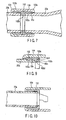
- FIG. 9 shows a modification of the second embodiment.
- the same components of the modification as those of the first embodiment are denoted by the same reference numerals, and the explanation about them is omitted.
- the abutment surface portion 102b as the abutment member is formed on the projecting end portion of the stopper nut 102, and the abutment surface portion 102b inwardly projects in the diameter direction.
- the inner side surface of the abutment surface portion 102b is intimately engaged with the truss structural member 20a.
- the grooved portion 102c is formed in the root of the inner side surface of the abutment surface portion 102b.
- the grooved portion 102c makes the thickness of the root of the abutment surface portion 102b being thinner to form the root as the elastically deformable portion and to produce a large cavity portion 102d.
- a recessed portion 102e is formed in a portion of the outer peripheral surface of the stopper nut 102, and a through hole 102f, which communicates with the cavity portion 102d, is formed in the bottom of the recessed portion 102e.
- the length of the truss structural member member on both end portions of which couplers are attached is determined by the length from the abutment surface of the abutment surface portion 102b of the stopper nut 102 mounted on one end portion of the truss structural member 20a to the abutment surface of the abutment surface portion 102b of the stopper nut 102 mounted on the other end portion of the truss structural member 20a.
- the truss structural member 20a is cut off to a length shorter than a predetermined length, it is possible to set the length between the abutment surfaces of the abutment surface portions 102b of the stopper nuts 102 mounted on the both end portions of the truss structural member 20a to the predetermined length by adjusting a degree of screwing the stopper nut 102 on each end portion of the truss structural member 20a, and by charging the adhesive into the cavity portion 102d through the through hole 102f or by fixing the female screw portion of the stopper nut 102 to the male screw portion of each end portion of the truss structural member 20a.
- the truss structural member 20a is made of a steel pipe or a CRP pipe having no coupler and the like on both ends thereof, and the length of the truss structural member 20a having the couplers on both ends thereof is determined by the length between the abutment surfaces of the couplers.
- FIG. 10 shows another modification of the second embodiment, and the same components as those of the first embodiment are denoted by the same reference numerals, and the explanation thereof is omitted.
- This modification is used for a coupling apparatus in which a relatively small load is exerted on couplers 100a, 100b.
- a stopper ring 112 as an abutment member is fixed by adhesive or by welding to the truss structural member 20a, thereby the manufacturing process and assembling process for the truss structural member 20a with the couplers can be improved and the costs needed for these processes can be reduced.
- the stopper nut 102 and the coupler main body 104 can be accurately disposed on each of the end portions of the truss structural member 20a without being affected by a finished state of the end faces of the end portions of truss structural member 20a, it is possible to cut a pipe stock (for example, a steel pipe stock) into the truss structural member 20a in a construction site and to fix the couplers each composed of the stopper nut 102 and the coupler main body 104 on both end portions of the truss structural member 20a in the construction site with high accuracy.
- a pipe stock for example, a steel pipe stock
- the truss structural member 20a when the truss structural member 20a is made of the pipe, the truss structural member 20a can accomodates harnesses and connectors. Further, the truss structural member 20a with the couplers 100a, 100b can be used to form an artificial limb such as an artificial hand and an artificial leg, and also enjoys the above described various advantages. Therefore, the truss structural member 20a with the couplers 100a, 100b can be used in a wide variety of technical fields.
- the gaps between the engaging projections 106 and the engaging recesses 108 of the coupler main bodies 104 may be filled by welding or with a strong plastic such as an adhesive (an epoxy adhesive, for example Araldite made by Vantico (former name; Ciba-Geigy)) and the like and solidified it.
- an adhesive an epoxy adhesive, for example Araldite made by Vantico (former name; Ciba-Geigy)
- the strength of the couplers coupled with each other can be improved and the couplers coupled with each other can be used semipermanently.
- the coupling apparatus for structural members includes a pair of couplers 22a, 22b that are mounted on the structural members 20a, 20b independent of each other and can be detachably coupled with each other to couple the structural members 20a, 20b with each other.
- FIGS. 11A and 11B show only one coupler 22a.
- the structural member 20a on which the one coupler 22a is mounted is a tubular truss structural member and formed of, for example, CFRP (Carbon Fiber Reinforced Plastic).
- CFRP Carbon Fiber Reinforced Plastic
- the structural member 20a may have other shape and may be formed of various materials including various metals, various resins, or combinations thereof.
- the one coupler 22a may be mounted on only one end portion of the tubular truss structural member or on each of both end portions thereof as a predetermined position of the tubular truss structural member constituting the structural member 20a.
- the structural member 20b on which the other coupler 22b is mounted is a node (tying point) member, and the other coupler 22b is mounted at a predetermined position on the outer peripheral surface of the node (tying point) member.
- Each of the pair of couplers 22a, 22b includes a coupler main body 24 formed in a tubular shape.
- the coupler main body 24 may be formed of various arbitrary materials likewise the structural member 20a.
- the above described tubular shape is a cylindrical shape.
- a plurality of engaging projections 26 are disposed on the projecting end of the coupler main body 24 and project along the center line C of the cylindrical shape from a plurality of positions spaced apart from each other at predetermined intervals in the circumferential direction of the cylindrical shape.
- An engaging hook 28 projects from the projecting end portion of each of the plurality of engaging projections 26 in the predetermined one circumferential direction.
- the coupler main body 24 of the one coupler 22a is rotated in the predetermined one circumferential direction with respect to the coupler main body 24 of the other coupler 22b, thereby the plurality of engaging hooks 28 of the plurality of engaging projections 26 of the one coupler 22a are engaged with the plurality of engaging hooks 28 of the plurality of engaging projections 26 of the other coupler 22b in a direction where the couplers 22a, 22b are separated from each other along the center line C.
- the engaging hooks 28 of the engaging projections 26 of the coupler main body 24 of each of the couplers 22a, 22b have engaging surfaces 28a which are in contact with each other when the engaging hooks 28 of the engaging projections 26 of the one coupler 22a are engaged with the engaging hooks 28 of the engaging projections 26 of the other coupler 22b.
- Each engaging surface 28a slants from an imaginary plane ⁇ orthogonal to the above center line C toward the projecting end of the engaging projection 26 corresponding to the engaging surfaces 28a.
- the slant angle ⁇ is so set that, even if the pair of couplers 22a, 22b are pulled in a direction where they are separated from each other along the center line C while the engaging surfaces 28a of the engaging hooks 28 of the engaging projections 26 of the coupler main bodies 24 of one coupler 22a are engaged with those of the other coupler 22b, the engagement of the engaging surfaces 28a with each other can be stably maintained by friction force exerted on the engaging surfaces 28a engaging with each other.
- Such a slant angle ⁇ is in a range between, for example, 1 and 2°.
- Such a slant angle makes the above described engaging work being easy, also makes the disengaging work being easy, and makes the mutual engagement of the couplers being maintained surely, even if the outside dimensions of each of the engaging projections 26 and those of the engaging hooks 28 of the pair of couplers 22a, 22b are so set that the pair of couplers 22a, 22b do not substantially move a directions along the center lines C thereof while any of compression force and tension force is exerted on the couplers 22a, 22b in the directions along the center lines C thereof after the above described engagement is performed.
- the cylindrical coupler main body 24 has an inner flange 24a at the end portion thereof opposite to the projecting end portion where the plurality of engaging projections 26 project in the direction along the center line C.
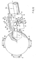
- Each of the pair of couplers 22a, 22b further includes a coupling direction changing mechanism 30 by which the coupler main body 24 can be connected to the predetermined position on the structural member 20a or 20b corresponding to the coupler main body 24 in a state that the center line of the coupler main body 24 directs in a desired direction.
- the coupling direction changing mechanism 30 includes a spherical supporting portion 32 and a spherical surface holding portion 34.
- the spherical supporting portion 32 includes at least a portion 32a of a spherical surface fixed to a predetermined position of the structural member 20a or 20b corresponding to the coupler main body 24 of the coupler 22a or the coupler 22b.
- the spherical surface holding portion 34 holds at least the portion 32a of the spherical surface of the spherical supporting portion 32, can slide on at least the portion 32a of the spherical surface, and is connected to the coupler main body 24 of the coupler 22a or 22b.
- the spherical surface holding portion 34 is connected to the coupler main body 24 in the inner hole of the coupler main body 24.
- a spherical supporting recess 34a which is composed of at least a portion of a spherical surface having a diameter substantially similar to that of at least the portion 32a of the spherical surface of the spherical supporting portion 32, must be formed in the spherical surface holding portion 34.
- the spherical surface holding portion 34 in the embodiment is composed of two blocks which are divided along a division plane parallel to the center line C of the coupler main body 24.
- the two blocks of the spherical surface holding portion 34 are separated from each other outside of the inner hole of the coupler main body 24, they are covered on at least the portion 32a of the spherical surface of the spherical supporting portion 32 so as to wrap at least the portion 32a of the spherical surface of the spherical supporting portion 32 with the spherical supporting recess 34a. Then, the two blocks are inserted into the inner hole of the coupler main body 24 in this state as shown in FIGS. 11A and 11B and are held in the inner hole.
- the spherical surface holding portion 34 may be held in the inner hole only by the friction force generated between the inner peripheral surface of the inner hole and the outer peripheral surface of the spherical surface holding portion 34. However, it can be more strongly held by a known fixing means such as an adhesive, a fixing screw, or the like.
- the spherical surface holding portion 34 may be composed of a plurality of blocks divided along a plurality of division planes parallel to the center line C of the coupler main body 24.
- the center line C of the coupler main body 24 of the one coupler 22a slants with respect to the normal V at the predetermined position of the other structural member 20b on which the other coupler 22b is mounted
- the center line C of the coupler main body 24 of the other coupler 22a is slanted with respect to the normal V at the predetermined position of the other structural member 20b by the coupling direction changing mechanism 30 so that the center line C of the coupler main body 24 of the other coupler 22a aligns with the center line C of the coupler main body 24 of the one coupler 22a.
- the pair of couplers 22a, 22b can be coupled with each other, namely, the one structural member 20a can be coupled with the other structural member 20b. Further, even if the outer dimensions of each of the one structural member 20a and the other structural member 20b, in particular, the length thereof along the center line C and the normal V is greatly changed due to thermal expansion, thermal contraction, or the dimensional tolerances of components in manufacture and assembly, the pair of couplers 22a, 22b can be appropriately coupled with each other regardless of the above change by moving the spherical surface holding portion 34 in the inner hole of the coupler main body 24 in a direction along the center line C or the normal V.
- the fixing means such as the adhesive, the fixing screw, or the like as described above, it is preferable to use the fixing means after the couplers 22a, 22b are appropriately copupled with each other.
- the one structural member 20a on which the one coupler 22a is mounted and the other structural member 20b on which the other coupler 22b is mounted are not only independent of each other but also have a different arrangement. However, they may have the same arrangement, namely, the other structural member 20b, for example, may be the same tubular truss structural member as the one structural member 20a.
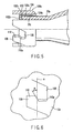
- FIGS. 13A, 13B , 14 , and 15 a coupling apparatus for structural members according to a fourth embodiment will be described in detail with reference to FIGS. 13A, 13B , 14 , and 15 .
- the coupling apparatus for structural members according to the fourth embodiment of the present invention like the coupling apparatus for structural members according to the third embodiment of the present invention described above with reference to FIGS. 11A, 11B , and 12 , also includes a pair of couplers 42a, 42b that are mounted on the structural members 40a, 40b independent of each other and can be detachably coupled with each other to couple the structural members 40a, 40b with each other.
- FIGS. 13A and 13B show only one coupler 42a.
- the structural member 40a on which the one coupler 42a is mounted is a tubular truss structural member and formed of, for example, CFRP (Carbon Fiber Reinforced Plastic).
- CFRP Carbon Fiber Reinforced Plastic
- the structural member 40a may have other shape and may be formed of various materials including various metals, various resins, or combinations thereof.
- the one coupler 42a may be mounted on only one end portion of the tubular truss structural member or on each of both end portions thereof as a predetermined position of the tubular truss structural member constituting the structural member 40a.
- the structural member 40b on which the other coupler 42b is mounted is a node (tying point) member, and the other coupler 42b is mounted at a predetermined position on the outer peripheral surface of the node (tying point) member.
- Each of the pair of couplers 42a, 42b includes a coupler main body 44 formed in a tubular shape.
- the coupler main body 44 may be formed of various arbitrary materials likewise the structural member 40a.
- the above described tubular shape is a cylindrical shape.
- a plurality of engaging projections 46 are disposed on the projecting end of the coupler main body 44 and project along the center line C of the cylindrical shape from a plurality of positions spaced apart from each other at predetermined intervals in the circumferential direction of the cylindrical shape.
- An engaging hook 48 projects from the projecting end portion of each of the plurality of engaging projections 46 in the predetermined one circumferential direction.
- the coupler main body 44 of the one coupler 42a is rotated in the predetermined one circumferential direction with respect to the coupler main body 44 of the other coupler 42b, thereby the plurality of engaging hooks 48 of the plurality of engaging projections 46 of the one coupler 42a are engaged with the plurality of engaging hooks 48 of the plurality of engaging projections 46 of the other coupler 42b in a direction where the couplers 42a, 42b are separated from each other along the center line C.
- the engaging hooks 48 of the engaging projections 46 of the coupler main body 44 of each of the couplers 42a, 42b have engaging surfaces 48a which are in contact with each other when the engaging hooks 48 of the engaging projections 46 of the one coupler 42a are engaged with the engaging hooks 48 of the engaging projections 46 of the other coupler 42b.
- Each engaging surface 48a slants from an imaginary plane ⁇ orthogonal to the above center line C toward the projecting end of the engaging projection 46 corresponding to the engaging surfaces 48a.
- the slant angle ⁇ is so set that, even if the pair of couplers 42a, 42b are pulled in a direction where they are separated from each other along the center line C while the engaging surfaces 48a of the engaging hooks 48 of the engaging projections 46 of the coupler main bodies 44 of one coupler 42a are engaged with those of the other coupler 42b, the engagement of the engaging surfaces 48a with each other can be stably maintained by friction force exerted on the engaging surfaces 48a engaging with each other.
- Such a slant angle ⁇ is in a range between, for example, 1 and 2°.
- Such a slant angle makes the above described engaging work being easy, also makes the disengaging work being easy, and makes the mutual engagement of the couplers being maintained surely, even if the outside dimensions of each of the engaging projections 46 and those of the engaging hooks 48 of the pair of couplers 42a, 42b are so set that the pair of couplers 42a, 42b do not substantially move a directions along the center lines C thereof while any of compression force and tension force is exerted on the couplers 42a, 42b in the directions along the center lines C thereof after the above descibed engagement is performed.
- the cylindrical coupler main body 44 has an inner flange 44a at the end portion thereof opposite to the projecting end portion where the plurality of engaging projections 46 project in the direction along the center line C.
- the pair of couplers 42a, 42b according to the fourth embodiment and including the coupler main bodies 44, the plurality of engaging projections 46, the plurality of engaging hooks 48, and the engaging surfaces 48a have the same arrangements as those of the pair of couplers 22a, 22b according to the third embodiment and including the coupler main bodies 24, the plurality of engaging projections 26, the plurality of engaging hooks 28, and the engaging surface 28a as described above.
- the fourth embodiment is different from the third embodiment in the arrangement of each of coupling direction changing mechanisms 50 which are additionally provided in the pair of couplers 42a, 42b.
- the coupling direction changing mechanism 50 can connect the coupler main body 44 to the predetermined position on the structural member 40a or 40b corresponding to the coupler main body 44 in a state that the center line of the coupler main body 44 directs in a desired direction.
- Each of the coupling direction changing mechanism 50 includes an entering portion 52 and a diameter-enlarged portion 54 fixed to the entering portion 52.
- the entering portion 52 is fixed to a predetermined position of the structural member 40a or 40b to which the coupler main body 44 of the couplers 42a or 42b corresponds, and is entered in the inner hole of the coupler main body 44 of the corresponding coupler 42a or 42b.
- the coupling direction changing mechanism 50 further includes at least two thickness-changing washers 56a, 56b, which annually extend around the center line C in the inner hole on the side opposite to the entering end of the entering portion 52 with respect to the diameter-enlarged portion 54 and which are disposed side by side in a direction along the center line C of the inner hole.
- the coupling direction changing mechanism 50 includes a radial direction movement guide portion 58, which is disposed in the inner hole on the entering end side of the entering portion 52 with respect to the diameter-enlarged portion 54 and abutted against the end surface of the diameter-enlarged portion 54 on the entering end side and which permits the diameter-enlarged portion 54 to move in the radial direction of the inner hole.
- one end surface 57a of the washer in the direction along the center line thereof extends in a direction orthogonal to the center line C, and the other end surface 57b thereof extends in a direction obliquely intersecting the center line C thereof.
- a surface 58a of the radial direction movement guide portion 58 against which the end surface of the diameter-enlarged portion 54 on the entering end side thereof is abutted has a concave shape which is recessed in the projecting direction of the entering portion 52.
- the diameter-enlarged portion 54 is clamped in the inner hole in the direction along the center line C of the inner hole by the at least two thickness-changing washers 56a, 56b and the radial direction movement guide portion 58.
- the radial direction movement guide portion 58 is moved in the radial direction of the inner hole on the end surface of the diameter-enlarged portion 54 on the entering end side thereof, thereby the coupler main body 44 of the coupler 42a or 42b corresponding thereto can be moved in the radial direction of the inner hole with respect to the projecting end of the entering portion 52.
- the coupler main body 44 which holds the radial direction movement guide portion 58, slants so as to slant the center line C thereof with respect to the projecting end of the entering portion 52, namely, with respect to the normal V at the above described predetermined position of the structural members 40a or 40b corresponding thereto.
- one of the two thickness-changing washers 56a, 56b can be moved in the circumferential direction relatively to the other of them by, for example, the following manner. That is, a not shown washer operating slot, which extends a predetermined length in the circumferential direction of an outer peripheral wall of the coupler main body 44, is previously formed in the outer peripheral wall in a portion corresponding to the outer peripheral surface of the one of the two thickness-changing washers 56a, 56b, and further a not shown tool hook depression is previously formed in the outer peripheral surface of the one of the two thickness-changing washers 56a, 56b.
- the direction in which the coupler main body 44, which holds the radial direction movement guide portion 58, slants its center line C with respect to the projecting end of the entering portion 52, namely, with respect to the normal V at the predetermined positions of the corresponding structural member 40a or 40b, can be arbitrarily set.
- Both the two thickness-changing washers 56a, 56b can be simultaneously moved in the circumferential direction by, for example, the following manner. That is, a not shown washer operating slot, which extends a predetermined length in the circumferential direction of the outer peripheral surface of the coupler main body 44, is also previously formed in the outer peripheral wall of the coupler main body 44 in a portion corresponding to the outer peripheral surface of the other of the two thickness-changing washers 56a, 56b, and further a not shown tool hook depression is also previously formed in the outer peripheral surface of the other of the two thickness-changing washers 56a, 56b.
- not shown tools are inserted into the two not shown washer operating slots, and the inserting ends of the not shown tools are hooked in the tool hook depressions in the outer peripheral surfaces of both the two thickness-changing washers 56a, 56b, thereby both the thickness-changing washers 56a, 56b are simultaneously moved in the circumferential direction by the not shown tools.
- the two thickness-changing washers 56a, 56b and the radial direction movement guide portion 58 may be held in the inner hole only by the friction force generated between the inner peripheral surface of the inner hole and each of the outer peripheral surfaces of thickness-changing washers 56a, 56b and the radial direction movement guide portion 58.
- they can be more strongly held by a known fixing means such as an adhesive, fixing screw, or the like.
- the center line C of the coupler main body 44 of the one coupler 42a slants with respect to the normal V at the predetermined position of the other structural member 40b on which the other coupler 42b is mounted
- the center line C of the coupler main body 44 of the other coupler 42b is slanted with respect to the normal V at the predetermined position of the other structural member 40b by the coupling direction changing mechanism 50 so that the center line C of the coupler main body 44 of the other coupler 42b aligns with the center line C of the coupler main body 44 of the one coupler 42a.
- the pair of couplers 42a, 42b can be coupled with each other, namely, the one structural member 40a can be coupled with the other structural member 40b. Further, even if the outer dimensions of each of the one structural member 40a and the other structural member 40b, in particular, the length thereof along the center line C and the normal V is greatly changed due to thermal expansion, thermal contraction, or the dimensional tolerances of components in manufacture and assembly, the pair of couplers 42a, 42b can be appropriately coupled with each other regardless of the above change by the following manners.
- an annular bag in which a gel-like material having a very small amount of thermal expansion and thermal contraction is hermetically sealed, or a packing of, for example, silicone rubber, fluororubber, or the like may be interposed between each of the structural members 40a, 40b and the two thickness-changing washers 56a, 56b.
- a gel-like material having a very small amount of thermal expansion and thermal contraction is hermetically sealed, a thermoplastic resin, or an elastic material, for example, silicone rubber, fluororubber in place of the thickness-changing washers 56a, 56b.
- the thickness-changing washers 56a, 56b are composed of a thermoplastic resin
- heaters are disposed therein. And, when the construction is deformed in their entireties by an uneven increase in temperature therein, the thermoplastic resin is softened by using the heaters so that the relative angle relationship between the structural members 40a, 40b can be easily changed and the deformation of the construction due to the uneven increase in temperature therein can be absorbed.
- the two thickness-changing washers 56a, 56b and the radial direction movement guide portion 58 are strongly held in the inner hole by the known fixing means such as the adhesive, fixing screw, or the like as described above, it is preferable to use the fixing means after the pair of couplers 42a, 42b are appropriately coupled with each other.
- the thickness-changing washers 56a, 56b and the radial direction movement guide portion 58 are composed a thermosetting resin or a photo-setting resin, it is preferable to set the resin by applying heat or light thereto after the pair of couplers 42a, 42b are coupled with each other.
- the one structural member 40a on which the one coupler 42a is mounted and the other structural member 40b on which the other coupler 42b is mounted are not only independent of each other but also have a different arrangement. However, they may have the same arrangement as to each other, namely, the other coupler 42b, for example, may be composed of the same tubular truss structural member as the one structural member 40a.
- each of the pair of couplers 22a, 22b includes the coupling direction changing mechanism 30.
- at least one of the pair of couplers 22a, 22b may include the coupling direction changing mechanism 30.
- FIG. 16 shows a state that the one coupler 22a provided with the coupling direction changing mechanism 30 is coupled with the other coupler 22b' not provided with the coupling direction changing mechanism 30, and the other coupler 22b' is mounted at the predetermined position on the structural member 20b corresponding thereto with a fixing support portion 33a of a coupling direction fixing mechanism 33.
- the coupling direction fixing mechanism 33 cannot slant the coupler 22b' with respect to the normal V at the above predetermined position.
- FIG. 16 also shows a state that the one structural member 20a, which is coupled with the one coupler 22a with the coupling direction changing mechanism 30, slants with reference to the normal V at the predetermined position of the other structural member 20b.
- the fixing support portion 33a of the coupling direction fixing mechanism 33 can be rotated in the inner hole of the coupler main body 24 of the other coupler 22b' in the circumferential direction of the inner hole, and can be moved in the inner hole in the direction along the center line C of the inner hole. And, the rotation of the fixing support portion 33a of the coupling direction fixing mechanism 33 in the circumferential direction and the movement thereof in the direction along the center line can be arbitrarily fixed by using a known fixing means, for example, a fixing screw, an adhesive, or the like to the coupler main body 24 of the other coupler 22b'.
- a known fixing means for example, a fixing screw, an adhesive, or the like
- each of the pair of couplers 42a, 42b includes the coupling direction changing mechanism 50.
- at least one of the couplers 42a, 42b may include the coupling direction changing mechanism 50.
- the other of the pair of couplers 42a, 42b is mounted at the predetermined position of the structural member corresponding thereto with the fixing support portion of the coupling direction fixing mechanism.
- the coupling direction fixing mechanism cannot slant the other coupler with respect to the normal at the above predetermined position.
- the fixing support portion of the coupling direction fixing mechanism which is applied to the other of the pair of couplers 42a, 42b of the fourth embodiment, can be rotated in the inner hole of the coupler main body of the other coupler in the circumferential direction of the inner hole, and can be moved in the inner hole in the direction along the center line of the inner hole.
- the rotation of the fixing support portion of the coupling direction fixing mechanism in the circumferential direction and the movement thereof in the direction along the center line can be also arbitrarily fixed by using the known fixing means, for example, the fixing screw, the adhesive, or the like to the coupler main body of the other coupler.
- the coupling direction changing mechanism 30, which is employed in at least one of the pair of couplers 22a, 22b, and the coupling direction changing mechanism 50, which is employed in at least one of the pair of couplers 42a, 42b, in the coupling apparatuses according to the third and fourth embodiments can be employed in at least one of the pair of couplers 60a, 60b and at least one of the pair of couplers 110a, 100b of the coupling apparatuses according to the first and second embodiments described above and in both the pair of couplers 60a, 60b and both the pair of couplers 100a, 100b.
- the coupling apparatus for structural members according to the present invention is simple in structure and can make assembling and disassembling work of the construction being easy while the assembling and disassembling work is performed in the unstable environment, such as on the body floating on water, or in underwater, aerospace, or the like.
- the coupling apparatus for structural members according to the present invention is simple in structure, can make assembling and disassembling work of the construction being easy even if the assembling and disassembling work is performed in the unstable environment such as on the body floating on water or in the underwater, aerospace, or the like, and even if the assembling and disassembling work is performed in the environment where the construction is exposed to high temperature and low temperature for a long time period, and further prevents the construction from generating a large amount of deformation and stress due to temperature expansion and temperature contraction. Therefore, the coupling apparatus for structural members according to the present invention is appropriately used to assemble a large roofed construction, for example a dome, used on land and a construction used on water, underwater, or aerospace.
Landscapes
- Engineering & Computer Science (AREA)
- General Engineering & Computer Science (AREA)
- Mechanical Engineering (AREA)
- Joining Of Building Structures In Genera (AREA)
- Mutual Connection Of Rods And Tubes (AREA)
- Snaps, Bayonet Connections, Set Pins, And Snap Rings (AREA)
- Coupling Device And Connection With Printed Circuit (AREA)
- Orthopedics, Nursing, And Contraception (AREA)
- Finger-Pressure Massage (AREA)
- Light Receiving Elements (AREA)
- Seal Device For Vehicle (AREA)
- Memory System Of A Hierarchy Structure (AREA)
- Paper (AREA)
- Rod-Shaped Construction Members (AREA)
Abstract
Description
- The present invention relates to a coupling apparatus for structural members, including a pair of couplers which couples structural members independent of each other with each other.
- It is known well to assemble a large construction by coupling a plurality of structural members independent of each other. The European
patent application EP 0 770 809 A1 discloses a coupling for coupling hoses comprising a pair of coupling main bodies. Each main body has a sealing surface, a plurality of engaging projections and engaging recesses at the front end. The coupling main bodies can be coupled with each other by engaging the projections and the recesses of one main body with the recesses and projections of the other body. The engaging protections are provided with respective hooked anchor sections that are peripherally engaged to restrict actual movement and thus couple the pair of coupling main bodies. The Europeanpatent application EP 1 024 323 A1 discloses a joint for hoses based on a similar principle as described above. The Japanese patent applicationJP 09 280 454 - Further, a truss construction, for example, is well known as the described construction. Conventional truss constructions are assembled by coupling a plurality of structural members independent of each other by coupling apparatuses that use welding or fixing members such as bolts and the like.
- For example, Research Report of Shimizu Corporation (Vol. 65, 1997, 4) discloses a coupling apparatus for coupling a plurality of truss structural members with each other making use of bolts.
- As shown in
FIG. 17A , the conventional coupling apparatus includesnose cones 12 of stainless steel mounted on predetermined positions, or both ends of a tubular trussstructural member 10 formed of CFRP (Carbon Fiber Reinforced Plastic) by, for example rivets not shown. Each of thenose cones 12 has a truncated-conical shape, and a hightension steel bolt 14 is screwed into thenose cone 12 from the innner hole of the tubular trussstructural member 10. The portion of the shaft of thebolt 14 projected from thenose cone 12 is covered with analuminum alloy collar 16. A fixing pin 14a is studded in the above described portion of the shaft of thebolt 14, and alongitudinal groove 16a extending in a direction in which the shaft of thebolt 14 extends is formed on the innner peripheral surface of thecollar 16. The fixing pin 14a of the shaft of thebolt 14 projects into thelongitudinal groove 16a on the inner peripheral surface of thecollar 16. - The conventional coupling apparatus further includes a
spherical node member 18. Ascrew hole 18a is formed at a predetermined position of the outer peripheral surface of thenode member 18 as well as arecess 18b is formed at an inlet of thescrew hole 18a. - After the projecting end of the shaft of the
bolt 14 is aligned with the inlet of thescrew hole 18a at the predetermined position of the outer peripheral surface of thenode member 18, thecollar 16 is rotated in a predetermined direction. With this operation, thebolt 14 is also rotated in the predetermined direction together with thecollar 16, thereby the shaft of thebolt 14 is screwed into thescrew hole 18a. The shaft of thebolt 14 is continuously screwed until the fixing pin 14a thereof is accommodated in therecess 18b of the inlet of thescrew hole 18a. When the fixing pin 14a has been accommodated in therecess 18b, thebolt 14 can not be rotated by thecollar 16. - In the conventional coupling apparatus assembled as described above, compression force exerted between the tubular truss
structural member 10 and thenode member 18 is mainly supported by thecollar 16, and tension force exerted between the tubular trussstructural member 10 and thenode member 18 is mainly supported by thebolt 14. - When a node member 18', in the outer peripheral surface of which four screw holes are formed on one imaginary circle with a maximum diameter at the same intervals, is prepared, the one ends of the four tubular truss
structural members 10 can be coupled with the node member 18' as shown inFIG. 17B . - Further, when a
node member 18", in the outer peripheral surface of which two screw holes are formed at desired two positions, is prepared, the one ends of the two tubular trussstructural members 10 can be coupled with thenode member 18" as shown inFIG. 17C . - An increase in size of a construction inevitably increases the number of structural members to be coupled with each other, which makes an assembling work for the construction being troublesome.
- Moreover, in the above described conventional coupling apparatus, a work for aligning the projected end of the shaft of the
bolt 14 at the one end of the tubular trussstructural member 10 with the inlet of thescrew hole 18a at the predetermined position on the outer peripheral surface of thenode member 18 is very troublesome, and a work for rotating thecollar 16 in the predetermined direction to screw the shaft of thebolt 14 into thescrew hole 18a is also very troublesome. Further, after thebolt 14 is screwed into thescrew hole 18a as desired, thebolt 14 cannot be released from thescrew hole 18a. - The troublesome work for assembling a construction using the conventional coupling apparatus as described above becomes more troublesome when the above assembling work is performed in an unstable environment, such as on a body floating on water, or in underwater, aerospace, or the like.
- Moreover, in the above described conventional coupling apparatus, the assembling work becomes difficult unless dimensional accuracy is strictly controlled, and the assembling work becomes furthermore difficult when elements that constitute the structural member and the coupling apparatus are exposed to external environments of high temperature and low temperature, in which the elements are thermally expanded and contractiond, for a long period.
- Further, in the above environment, even after the assembling work is finished, the coupling apparatus is greatly deformed due to the thermal expansion and contraction of the elements that constitute the structural member and the coupling apparatus, thereby the coupling apparatus may be subjected to fatigue failure.
- The present invention is derived from the above described circumstances, an object of the present invention is to provide a coupling apparatus for structural members which is simple in structure and can make assembling and disassembling work of the construction being easy while the assembling and disassembling work is performed in the unstable environment, such as on the body floating on water, or in underwater, aerospace, or the like.
- In order to achieve the above described object of the present invention, a coupling apparatus for independent structural members comprises a pair of couplers which couples the structural members with each other, and is characterized in that each of the pair of couplers includes:
- a cylindrical inner coupler main body rotationally mounted on the structural member corresponding thereto at a predetermined position thereof;
- a cylindrical outer coupler main body rotationally fitted on the outer periphery of the inner coupler main body;
- a plurality of engaging projections disposed on each of the inner coupler main body and the outer coupler main body at the projecting end thereof opposite to the corresponding structural member, and projecting in a direction along the center line of each coupler main body from a plurality of positions spaced apart from each other at predetermined intervals in the circumferential direction of each coupler main body;
- an engaging hook projecting in one circumferential direction of the inner coupler main body from one side surface of the projecting end portion of each of the engaging projections of the inner coupler main body;
- an engaging hook projecting in the other circumferential direction of the outer coupler main body from the other side surface of the projecting end portion of each of the engaging projections of the outer coupler main body; and
- an urging unit interposed between the inner coupler main body and the outer coupler main body and urging the inner coupler main body and the outer coupler main body in opposite cicumferential directions, and
- when the plurality of engaging projections of the inner coupler main body and the plurality of engaging projections of the outer coupler main body of one coupler are inserted into a plurality of recesses between the plurality of engaging projections of the inner coupler main body and a plurality of recesses between the plurality of engaging projections of the outer coupler main body of the other coupler, the plurality of engaging hooks of the plurality of engaging projections of the inner coupler main body of the one coupler come into contact with the plurality of engaging hooks of the plurality of engaging projections of the inner coupler main body of the other coupler to rotate the inner coupler main body of the one coupler and the inner coupler main body of the other coupler with respect to each other in the predetermined opposite circumferential directions against the urging force of the urging unit, and thereafter the inner coupler main body of the one coupler and the inner coupler main body of the other coupler are rotated in the anti-predetermined opposite circumferential directions by the urging force of the urging unit, thereby the plurality of engaging hooks of the plurality of engaging projections of the inner coupler main body and the plurality of engaging hooks of the plurality of engaging projections of the outer coupler main body of the one coupler are engaged with the plurality of engaging hooks of the plurality of engaging projections of the inner coupler main body and the plurality of engaging hooks of the plurality of engaging projections of the outer coupler main body of the other coupler in a direction where the couplers are separated from each other along the center line of each of them.
- an abutment member fixed to a predetermined position of the structural member corresponding to the each coupler, the abutment member having an abutment surface;
- a cylindrical coupler main body disposed on the outer periphery of the abutment member and being rotational with respect to the predetermined position of the corresponding structural member;
- a plurality of engaging projections disposed on the coupler main body at the projecting end thereof opposite to the corresponding structural member, and projecting in a direction along the center line of the coupler main body from a plurality of positions arranged at predetermined intervals in the circumferential direction of the coupler main body; and
- an engaging hook projecting in one circumferential direction of the coupler main body from one side surface of projecting end portion of each of the engaging projections, and having an engaging surface slanting toward the projecting direction of the each engaging projection with respect to an imaginary surface orthogonal to the center line of the coupler maing body, and
- when the structural members corresponding to the pair of couplers are coupled with each other by the pair of couplers, the abutment surfaces of the abutment members of the structural members corresponding to the pair of couplers are abutted against each other.
-
-
FIG. 1 is a perspective view schematically showing a coupling apparatus for structural members according to a first embodiment of the present invention in a state that a pair of couplers are separated from each other; -
FIG. 2 is a side view schematically showing one of the pair of couplers shown inFIG. 1 with its upper half portion shown in a longitudinal section; -
FIG. 3 is a schematic side view showing the pair of couplers shown inFIG. 1 in a state that they are coupled with each other; -
FIG. 4 is a schematic side view showing a coupling apparatus for structural members according to an embodiment of the present invention as second embodiment in a state that a pair of couplers are coupled with each other with their upper half portions shown in a longitudinal section; -
FIG. 5 is a schematic side view showing one of the pair of couplers shown inFIG. 4 with its upper half portion shown in a longitudinal section; -
FIG. 6 is an enlarge view of one engaging hook of one of a plurality of engaging projections of a coupler main body of one coupler shown inFIG. 5 ; -
FIG. 7 is a schematic longitudinal sectional view for explaining a function of a pair of abutment members of the pair of couplers shown inFIG. 4 in a state that the pair of couplers are coupled with each other; -
FIG. 8A is a schematic longitudinal sectional view showing a state in which an abutment surface of an abutment member of one of the pair of couplers shown inFIG. 4 is damaged; -
FIG. 8B is a schematic longitudinal sectional view of a first modification of the abutment member of each of the pair of couplers shown inFIG. 4 in which the function of the abutment surface does not fail even if it is damaged as shown inFIG. 8A ; -
FIG. 8C is a schematic longitudinal sectional view of a second modification of the abutment member of each of the pair of couplers shown inFIG. 4 in which the function of an abutment surface does not fail even if it is damaged as shown inFIG. 8A ; -
FIG. 8D is a schematic longitudinal sectional view of a third modification of the abutment member of each of the pair of couplers shown inFIG. 4 in which the function of an abutment surface does not fail even if it is damaged as shown inFIG. 8A ; -
FIG. 9 is a schematic longitudinal sectional view showing a fourth modification of the abutment member of each of the pair of couplers shown inFIG. 4 ; -
FIG. 10 is a schematic longitudinal sectional view of a fourth modification of the abutment member of each of the pair of couplers shown inFIG. 4 ; -
FIG. 11A is a schematic longitudinal sectional view of one of a pair of couplers of a coupling apparatus for structural members according to an embodiment of the present invention as third embodiment; -
FIG. 11B is a schematic front view of the one coupler shown inFIG. 11A ; -
FIG. 12 is a half longitudinal sectional view of the pair of couplers of the coupling apparatus for structural members according to the third embodiment shown inFIGS. 11A and 11B , and schematically shows that the pair of couplers are coupled with each other and coupling direction changing mechanisms of the pair of couplers function; -
FIG. 13A is a schematic longitudinal sectional view of one of a pair of couplers of a coupling apparatus for structural members according to a fourth embodiment of the present invention; -
FIG. 13B is a schematic front view of the one coupler shown inFIG. 13A ; -
FIG. 14 is a side view schematically showing that the pair of couplers of the coupling apparatus for structural members according to the fourth embodiment shown inFIGS. 13A and 13B are coupled with each other and coupling direction changing mechanisms of the pair of couplers function; -
FIG. 15 is a schematic longitudinal sectional view of the pair of couplers of the coupling apparatus for structural members according to the fourth embodiment in the same condition as that inFIG. 14 ; -
FIG. 16 is a side view of a modification of the pair of couplers of the coupling apparatus for structural members according to the third embodiment shown inFIGS. 11A and 11B and schematically shows that the pair of couplers are coupled with each other and a coupling direction changing mechanism provided with only one of the pair of couplers functions; -
FIG. 17A schematically shows a main portion of a conventional coupling apparatus in an enlarged cross section; -
FIG. 17B is a view schematically showing that four structural members independent of each other are coupled with each other by the conventional coupling apparatus for structural members shown inFIG. 17A ; and -
FIG. 17C is a view schematically showing that two structural members independent of each other are coupled with each other by the conventional coupling apparatus for structural members shown inFIG. 17A . - Various embodiments and various modifications of a coupling apparatus for structural members of the present invention will be explained below in detail with reference to
FIGS. 1 to 16 of the accompanying drawings. - At first, a coupling apparatus for structural members according to a first embodiment of the present invention will be explained in detail with reference to
FIGS. 1 to 3 . - The coupling apparatus includes a pair of
couplers couplers main body 62 and a cylindrical outer couplermain body 64 located on the outer peripheral surface of the inner couplermain body 62. - The inner coupler
main body 62 is rotatably fitted into one end portion of a trussstructural member main body 64 is rotatably fitted on the outer peripheral surface of the inner couplermain body 62. - More specifically, a male screw portion N is formed on the outer peripheral surface of the one end portion of the truss
structural member 20a, and a female screw portion formed on the inner peripheral surface of acollar 66 is screwed on the male screw portion N. The outer peripheral surface of thecollar 66 projects outwardly from outer peripheral surface of the trussstructural member 20a in the radial direction of the trussstructural member 20a, and the inner peripheral surface of the inner couplermain body 62 is rotatably fitted on the outer peripheral surface of thecollar 66. - An
inner flange 62a is formed on the inner peripheral surface of the inner couplermain body 62 at the end thereof located on the trussstructural member 20a. Theinner flange 62a engages with the inner end of thecollar 66 located on the trussstructural member 20a in a direction along the center line of the inner couplermain body 62 and forms a drop-off preventing projection for preventing the dropp-off of the inner couplermain body 62 from thecollar 66. Aninner flange 64a is formed on the outer couplermain body 64 at the end thereof located on the trussstructural member 20a. Theinner flange 64a of the outer couplermain body 64 engages with the end of theinner flange 60a of the inner couplermain body 62 located on the trussstructural member 20a in the direction along the center line and forms a drop-off preventing projection for preventing the dropp-off of the outer couplermain body 64 from the inner couplermain body 62. -
Holes 68 are formed in the outer couplermain body 64 from the inner couplermain body 62 at their positions alighning with each other in a radial direction with respect to the center line when the pair ofcouplers pin 70, which acts as a circumferential position fixing means for fixing a relative circumferential position of the outer couplermain body 64 to the inner couplermain body 62, can be inserted into thehole 68. - The inner coupler
main body 62 and the outer couplermain body 64, which are fixed to each other by the fixingpin 70, are free to rotate together in a circumferential direction of the trussstructural member 20a with respect to the one end portion of the trussstructural member 20a. - A
hole 72 is formed in the one end portion of the trussstructural member 20a at a position thereof located near to theinner flange 64a of the outer couplermain body 64 when the pair ofcouplers - A
wedge 74 can be inserted into thehole 72, and thewedge 74 acts as an axial poison fixing means for fixing the position of the outer couplermain body 64 with respect to the one end portion of thetruss member 20a and to the inner couplermain body 62 in the direction along the center line. - The size of the
wedge 74 is so set that the outer end portion of thewedge 74 projects from the outer peripheral surface of the trussstructural member 20a after thewedge 74 is pushed into thehole 72. - The
wedge 74 prevents the outer couplermain body 64 from moving in the direction along the center line with respect to the one end portion of the trussstructural member 20a and to the inner couplermain body 62 while the pair ofcouplers - A centering
cylindrical member 76 acting as a position alignment member is inserted into the inner hole of the inner couplermain body 62. The outer peripheral surface of the centeringcylindrical member 76 is formed in a stepped shape. Alarge diameter portion 76a of the centeringcylindrical member 76 is movably fitted on the inner peripheral surface of the inner couplermain body 62, and asmall diameter portion 76b thereof is movably fitted on the inner peripheral surface of the one end portion of the trussstructural member 20a. - The end face of the centering
cylindrical member 76, which is far from the trussstructural member 20a, is located nearer to the trussstructural member 20a than the end face of the inner couplermain body 62, which is far from the trussstructural member 20a. Anannular packing 78 is attached to the end face of the centeringcylindrical member 76 and projects therefrom in the direction along the center line. - When the pair of
couplers cylindrical members 76 abut thepackings 78 against each other and arrange the center lines of the inner couplermain body 62 and the outer couplermain body 64 of one of the pair ofcouplers main body 62 and the outer couplermain body 64 of the other in the radial directions thereof. - The size of the centering
cylindrical member 76 is so set that it is free to move with respect to the inner couplermain body 62 and the trussstructural member 20a. Accordingly, even if the trussstructural member 20a is inclined only slightly with respect to the horizontal line before the pair ofcouplers cylindrical member 76 is easily dropped off from the inner couplermain body 62 and the trussstructural member 20a. - To prevent this easy dropping-off, an O-
ring 80 is fitted in anannular groove 76c formed in the outer peripheral surface of thesmall diameter portion 76b of the centeringcylindrical member 76. The friction force generated between the inner peripheral surface of the one end portion of the trussstructural member 20a and the O-ring 80 on the outer peripheral surface of thesmall diameter portion 76b of the centeringcylindrical member 76 prevents the easy dropping-off. - A plurality of engaging
projections 82 are disposed on the projecting end of each of the inner couplermain body 62 and the outer couplermain body 64 so as to project in the direction along the center line from a plurality of positions spaced apart at predetermined intervals from each other in the circumferential direction of each of the inner couplermain body 62 and the outer couplermain body 64, and engagingrecesses 84 are formed between these engagingprojections 82. - When the pair of
couplers projections 82 of the inner couplermain body 62 of the onecoupler 60a are inserted into the plurality of engagingrecesses 84 of the inner couplermain body 62 of theother coupler 60b. Further, at the same time, the plurality of engagingprojections 82 of the inner couplermain body 62 of theother coupler 60b are inserted into the plurality of engagingrecesses 84 of the inner couplermain body 62 of the onecoupler 60a. - Also, the plurality of engaging
projections 82 of the outer couplermain body 64 of the onecoupler 60a are inserted into the plurality of engagingrecesses 84 of the outer couplermain body 64 of theother coupler 60b. Further, at the same time, the plurality of engagingprojections 82 of the outer couplermain body 64 of theother coupler 60b are inserted into the plurality of engagingrecesses 84 of the outer couplermain body 64 of the onecoupler 60a. - The size of each engaging
recess 84 in the circumferential direction is so set that it is somewhat larger than that of each engagingprojection 82. Accordingly, the inner and outer couplermain bodies couplers main bodies projections 82 are inserted into the engagingrecesses 84 as described above. - An engaging
hook 86 is formed on one side surface of the projecting end portion of each engagingprojection 82 , the one side surface facing in one circumferential direction, and the engaginghook 86 projects in the one circumferential direction. In each of the pair ofcouplers hooks 86 of the inner couplermain body 62 project from the one side surfaces of the projecting end portions of the engagingprojections 82 in the one circumferential direction, and the engaginghooks 86 of the outer couplermain body 64 project from the other side surfaces of the projecting end portions of the engagingprojections 82 in the other circumferential direction. - As shown in
FIG. 1 , in a state that the pair ofcouplers projections 82 of the inner couplermain body 62 of one coupler and those of the other coupler oppositely project in the circumferential direction, and also the engaging hooks 86 on the engagingprojections 82 of the outer couplermain body 64 of one coupler and those of the other coupler oppositely project in the circumferential direction. - Accordingly, when one of the pair of
couplers projections 82 of eachcoupler recesses 84 of each facing one, the engaginghooks 86 of the one coupler and those of the other coupler, which are oppositely projected in the circumferential direction, can be engageable in a direction along the center lines thereof. - The engaging surface of each engaging
hook 86 is inclined with a predetermined angle with respect to the circumferential direction in an overhung state. Accordingly, when a load is exerted on the pair ofcouplers hooks 86 thereof are engaged with each other, the engaginghooks 86 are more strongly engaged with each other, thereby separation of the inner couplermain bodies 62 from each other and separation of the outer couplermain bodies 64 from each other can be more securely prevented. - In a state that the engaging
hooks 86 are engaged with each other, gaps exist between the projecting end faces of the engagingprojections 82 and the bottom surfaces of the engaging recesses 84. Accordingly, the engagingprojections 82 can be moved in the engagingrecesses 84 more deeply in the direction along the center line. - An urging
unit 88 is disposed and exposed on the outer peripheral surface of the outer couplermain body 64. The urgingunit 88 includes aslot 90, astopper pin 92, areceiver pin 94, and atension spring 96. Theslot 90 is formed in the outer couplermain body 64 to extend in the circumferential direction, thestopper pin 92 is inserted in theslot 90 and planted in the outer peripheral surface of the inner couplermain body 62, thereceiver pin 94 is disposed at a position near to an end of theslot 90 on the outer peripheral surface of the outer couplermain body 64, and thetension spring 96 is stretched between thereceiver pin 94 and thestopper pin 92. - That is, the urging
unit 88 is interposed between the inner couplermain body 62 and the outer couplermain body 64 and elastically urges the inner couplermain body 62 and the outer couplermain body 64 by the tension force so that they are rotated in opposite circumferential directions with respect to each other. - In each of the pair of
couplers stopper pin 92 and thereceiver pin 94, which constitute the urgingunit 88, are disposed at opposite positions with respect to theslot 90 in the circumferential directions, as well as the engaginghooks 86 disposed on the inner couplermain body 62 and those disposed on the outer couplermain body 64 are projected in the opposite circumferential directions with respect to each other. - In any way, the urging
unit 88 of each of the pair ofcouplers main body 62 and the outer couplermain body 64 to move the engaginghooks 86 of the inner couplermain body 62 and those of the outer couplermain body 64 are close to each other. - To couple the
coupler projections 82 of the inner and outer couplermain bodies coupler 60a are aligned with the engagingrecesses 84 of the inner and outer couplermain bodies other coupler 60b. - And, the engaging
recesses 84 of the inner and outer couplermain bodies coupler 60a are inevitably aligned with the engagingprojections 82 of the inner and outer couplermain bodies other coupler 60b. - Then, the one
coupler 60a is moved in the direction along the center line to approach to theother coupler 60b while maintaining their attitudes as they are. After all of the engagingprojections 82 of thecouplers recesses 84 thereof, the engaginghooks 86 of onecoupler 60a and those of theother coupler 60b are engaged with each other by the elastically urging action of the urgingunits 88. - When the
couplers structural members position fixing pin 70 into theholes 68 of the inner and outer couplermain bodies couplers main bodies wedge 74 is inserted into thehole 72 to press the centeringcylindrical member 76 as the aligning member in a direction where it projects from the trussstructural member 20a. As a result, the pair ofcouplers - The use of the
wedge 74 brings the more strong coupling of thecouplers structural members cylindrical members 76 through thewedge 74 and is directly transmitted to the trussstructural members wedge 74. Accordingly, when the compression load is extremely large, the existence of thewedge 74 is liable to be disadvantageous. - Further, since a construction is formed by combining many truss structural members, if each truss structural member has an error in size, a large error in size occurs when the many structuractural members are coupled with each other and the construction is formed. As a result, the coupling apparatus must be finished as it is designed, and occurrence of rattle is not preferable.
- Accordingly, the shape of the
wedge 74 is so set that the use of thewedge 74 brings an entirely and flatly crush of thepackings 78 at the projecting ends of the centeringcylindrical members 76 of the pair of couplers, a direct contact of the centeringcylindrical members 76 made of metal material with each other, and a pushing of the inner and outer couplermain bodies main bodies main bodies - The use of
wedge 74 as described above causes the inner and outer couplermain bodies main bodies couplers structural members - Further, in order to effectively and uniformly transmit the compression load exerted on the
truss atructural members wedge 74 and to obtain the strong coupling of thetruss atructural members cylindrical member 76 and the projecting end face of the trussstructural member 20a when thewedge 74 is inserted into thehole 72. - In order to fill the adhesive into the space as described above, adhesive filling
holes 98 are formed in the inner and outer couplermain bodies couplers - Further, the fixing
pin 70 may be a columnar shape or a tapered shape. Since the fixingpin 70 inserted into each of thecouplers main body 64 with respect to the inner couplermain body 62 in each of thecouplers couplers - Further, the fixing
pin 70 may be formed in a tapered shape reducing its diameter to a point thereof. At the same time, the diameter of thehole 68 of the inner couplermain body 62 may be formed smaller than that of thehole 68 of the outer couplermain body 64. In this case, even if the inner and outer couplermain bodies main bodies holes 68. - In the
couplers packings 78 of the centeringcylindrical members 76 are abutted against each other and to seal between them, and each of the centeringcylindrical members 76 centers the center lines of the inner and outer couplermain bodies couplers structural members - In the coupling apparatus for coupling the pipe shaped truss
structural members couplers structural members - Further, the stroke of each of the
couplers structural members structural members structural members - Since the
couplers main body 62 and the outer couplermain body 64, are coupled with each other, strength of thecouplers couplers couplers couplers - Since, in each of the
couplers hooks 86 of the inner couplermain body 62 and the engaginghooks 86 of the outer couplermain body 64 project in opposite directions and the urgingunit 88 elastically urges the engaginghooks couplers - Even if torque is exerted on the
couplers main bodies main bodies couplers couplers - In a state that the
couplers members cylindrical members cylindrical members couplers structural members 20a as pipes. - When the
couplers wedges 74 are removed, and the urgingunit 88 provided on any one of thecouplers - That is, for that operation, the outer coupler
main body 64 is held by one hand of an operator to prevent its rotation, and thestopper pin 92 of the urgingunit 88 is moved by the other hand in a direction opposite to the urging direction of thetension spring 96 so that thetension spring 96 is expanded. - By the above described operation, the inner coupler
main bodies 62 are rotated against the urging forces of the urgingunits 88 so that the engaginghooks main bodies 62 of thecouplers hooks 86, come into contact with each other, the engaginghooks couplers - The mutural coupling of the inner coupler
main bodies 62 and that of the outer couplermain bodies 64 in thecouplers couplers - As described above, there is no need to apply large torque on the
couplers couplers couplers couplers - The
couplers structural members - In a case that there is no need to separate the
couplers projections 82 and engagingrecesses 84 of one of the outer couplermain bodies - A coupling apparatus of this embodiment includes a pair of
couplers coupler 100b is connected to anode pipe 20b as a structural member connected to a node, and theother coupler 100a is connecte to a trussstructural member 20a. The trussstructural member 20a is connected to the node by coupling thecouplers - Since the
couplers coupler 100a will be explained in the following. Thecoupler 100a has a double structure composed of astopper nut 102 as an abutment member and a couplermain body 104 arranged on the outer peripheral surface of thestopper nut 102. - The
stopper nut 102 is formed of a cylindrical member and is screwed on and fixed to an end portion of the trussstructural member 20a. The couplermain body 104 is composed of a cylindrical member, and the inner peripheral surface thereof is rotatably fitted on the outer peripheral surface of thestopper nut 102. That is, anut engaging portion 104a is provided on the inner peripheral surface of the couplermain body 104, and the rear end face of thestopper nut 102 is abutted against thenut engaging portion 104a. The dimensional error of the projecting end portion of the trussstructural member 20a, which affects the coupling accuracy of the couplers when they are coupled with each other, can be absorbed by attaching thestopper nut 102. However, since they can be formed with high accuracy in a factory, the couplermain body 104 can be attached to the trussstructural member 20a (node side pipe 20b) with high accuracy. Further, the entire length of the trussstructural member 20a can be finely adjusted by adjusting a screwing amount of thestopper nut 102 on the projecting end portion of the trussstructural member 20a. In this case, it is preferable to fix thestopper nut 102 on the projecting end portion of the trussstructural member 20a with an adhesive after the fine adjustment. - To explain in more detail, a
male screw portion 20c is formed on the outer peripheral surface of the projecting end portion of the trussstructural member 20a, and afemale screw portion 102a, which is screwed on themale screw portion 20c, is formed on the inner peripheral surface of thestopper nut 102. Anabutment surface portion 102b is formed at the projecting end of thestopper nut 102 and inwardly projects in a diameter direction, and the inner side face of theabutment surface portion 102b is intimately engaged with the projecting end face of the trussstructural member 20a. Further, agrooved portion 102c is formed at the root of the inner side face of theabutment surface portion 102b, and a portion of theabutment surface portion 102b, which is thinned by thegrooved portion 102c, forms an elastically deformable portion. In a case that thefemale screw portion 102a is excessively screwed on themale screw portion 20c when thestopper nut 102 is fixed on the trussstructural member 20a, theabutment surface portion 102b of thestopper nut 102 is elastically deformed in the axial direction at thegrooved portion 102c and applies force to thestopper nut 102 in a direction where the backlash between thefemale screw portion 102a and themale screw portion 20c is disappeared so that thestopper nut 102 is prevented from being loosened. - When the above described effect, by which the loosening of the
stopper nut 102 is prevented, is obtained by the elastic deformation of thestopper nut 102 in the vicinity of thegrooved portion 102c formed in thestopper nut 102, there is a possibility that the flatness of theabutment surface portion 102b of thestopper nut 102 is deteriorated and a part of theabutment surface portion 102b is largely projected as indicated by "B" inFIG. 8A by the excess elastic deformation of thestopper nut 102 owing to the material of thestopper nut 102. In this case, the coupling function of the couplers may be deteriorated. To prevent this deterioration, an axially inwardly steppedportion 102g may be formed in theabutment surface portion 102b of thestopper nut 102 as shown inFIG. 8B or an axially inwardly slantedportion 102h may be formed in theabutment surface portion 102b of thestopper nut 102 as shown inFIG. 8C . With this configuration, even ifabutment surface portion 102b is excessively and elastically deformed at thegrooved portion 102c within a certain range, the excessively and elastically deformed portion does not largely and outwardly project in the axial direction. Further, by machining the surface of thestopper nut 102, which is abutted against the end face of the trussstructural member 20a, to make it function as aspring washer 102i, as shown inFIG. 8D , the effect for preventing the loosening of thestopper nut 102 can be obtained without deforming theabutment surface portion 102b. - A plurality of engaging
projections 106 are provided on the projecting end of the couplermain body 104 to project in the axial direction at positiones spaced apart from each other at predetermined intervals in the circumferential direction, and engagingrecesses 108 are formed between the engagingprojections 106. The engagingprojections 106 of the couplermain body 104 of onecoupler 100a are fitted into the engagingrecesses 108 of the couplermain body 104 of theother coupler 100b, and the engagingprojections 106 of the couplermain body 104 of theother coupler 100b are fitted into the engagingrecesses 108 of the couplermain body 104 of the onecoupler 100a, so that the pair of thecouplers - Note that the width of each of the engaging
recesses 108 is set larger than that of each of the engagingprojections 106 so that the couplermain body 104 is rotational by the predetermined distance in the circumferential direction in a state that the engagingprojections 106 are fitted into the engaging recesses 108. - Further, an engaging
hook 110, which projects in the circumferential direction, is formed on one side surface of each of the engagingprojections 106 of the couplermain bodies 104. After the pair ofcouplers main bodies 104 is moved to fit the engagingprojections 106 into the engagingrecesses 108, so that the engaginghooks 110 of the one coupler and those of the other can be engaged with each other. - The engaging
surface 110a of theengaging hook 110 slants in a direction approaching to the projecting end of the engaging projection 106 (plus direction) by a predetermined angle with respect to a plane orthogonal to the axial direction of the couplermain body 104. In the case that theengaging surface 110a of theengaging hook 110 is conventionally slanted in a minus direction, rotation force is exerted on thecouplers couplers engaging surface 110a of theengaging hook 110 is slanted in the plus direction as described above, rotation force is exerted on thecouplers couplers engaging surface 110a is set to 1° to 2° in consideration of a frictional angle. When the engaging angle θ of theengaging surface 110a is set to, for example, 2°, the length of theengaging surface 110a projected in the axial direction of the trussstructural member 20a is 0.1 mm to 0.3 mm in the axial direction of the couplermain body 104. - The position of the one coupler
main body 104 with respect to the other couplermain body 104 is exclusively determined by the difference between the size L of thestopper nut 102 and the size L' between thenut engaging portion 104a and the center of theengaging surface 110a (S denotes the line passing through the centers of the engagingsurfaces 110a). However, since thestopper nut 102 and the couplermain body 104 are machined with high accuracy in a factory so that the position of theabutment surface 102b of thestopper nut 102 and that of the the center of theengaging surface 110a of eachengaging hook 110 in the axial direction coincide with each other, a "play" between the pair of couplermain bodies 104 can be eliminated. - To couple the
couplers projections 106 of the couplermain body 104 of the onecoupler 100a are faced to the engagingrecesses 108 of the couplermain body 104 of theother coupler 100b, and the engagingrecesses 108 of the couplermain body 104 of the onecoupler 100a are inevitably faced to the engagingprojections 106 of the couplermain body 104 of theother coupler 100b. - Then, at least one of the coupler
main bodies 104 is moved in the axial direction while maintaining the above described circumfential positional relationship between thecouplers projections 106 of the couplermain bodies 104 are fitted into the engagingrecesses 108 thereof. Further, the couplermain bodies 104 are rotated in this state, and the engagingsurfaces 110a of the engaginghooks 110 are slightly moved in the circumferential direction while they are sliding on each other. As a result, the couplermain bodies 104 are coupled with each other, thereby thenode pipe 20b is coupled with the trussstructural member 20a. - At this time, the abutment surfaces 102b of the
stopper nuts 102 arranged in the inside of the couplermain bodies 104 are abutted against each other. Therefore, when a compression load is exerted on thenode pipe 20b and the trussstructural member 20a, the compression load is supported by the abutment surfaces 102b of thestopper nuts 102, and when a tension load is exerted on thenode pipe 20b and the trussstructural member 20a, the tension load is supported by the engagement of thestopper nuts 102 with thenut engaging portions 104a. - Accordingly, even if any of the compression load and the tension load is exerted on the pair of
couplers couplers node pipe 20b and the trussstructural member 20a are coupled with each other as in a condition in which they are directly coupled with each other. - Further, even if the end face of the truss
structural member 20a is obliquely cut, thestopper nut 102 can be coaxially fixed to the trussstructural member 20a without being affected by the shape of the end face of the trussstructural member 20a when thestopper nut 102 is screwed on themale screw portion 20c as shown inFIG. 4 , and at the same time the abutment surface of theabutment surface portion 102b of thestopper nut 102 is arranged to be orthogonal to the center line of the trussstructural member 20a. Therefore, since the abutment surfaces of theabutment surface portions 102b of thestopper nuts 102 are abutted against each other, the compression load exerted on thenode pipe 20b and the trussstructural member 20a can be supported thecouplers -
FIG. 9 shows a modification of the second embodiment. The same components of the modification as those of the first embodiment are denoted by the same reference numerals, and the explanation about them is omitted. Theabutment surface portion 102b as the abutment member is formed on the projecting end portion of thestopper nut 102, and theabutment surface portion 102b inwardly projects in the diameter direction. The inner side surface of theabutment surface portion 102b is intimately engaged with the trussstructural member 20a. Further, thegrooved portion 102c is formed in the root of the inner side surface of theabutment surface portion 102b. Thegrooved portion 102c makes the thickness of the root of theabutment surface portion 102b being thinner to form the root as the elastically deformable portion and to produce alarge cavity portion 102d. - A recessed
portion 102e is formed in a portion of the outer peripheral surface of thestopper nut 102, and a throughhole 102f, which communicates with thecavity portion 102d, is formed in the bottom of the recessedportion 102e. When an adhesive is charged into the throughhole 102f after thefemale screw portion 102a of thestopper nut 102 is screwed on and fixed to themale screw portion 20c of the trussstructural member 20a, thecavity portion 102d is filled with the adhesive, thereby thestopper nut 102 can be prevented from being loosened. - Further, the length of the truss structural member member on both end portions of which couplers are attached is determined by the length from the abutment surface of the
abutment surface portion 102b of thestopper nut 102 mounted on one end portion of the trussstructural member 20a to the abutment surface of theabutment surface portion 102b of thestopper nut 102 mounted on the other end portion of the trussstructural member 20a. Therefore, even if the trussstructural member 20a is cut off to a length shorter than a predetermined length, it is possible to set the length between the abutment surfaces of theabutment surface portions 102b of thestopper nuts 102 mounted on the both end portions of the trussstructural member 20a to the predetermined length by adjusting a degree of screwing thestopper nut 102 on each end portion of the trussstructural member 20a, and by charging the adhesive into thecavity portion 102d through the throughhole 102f or by fixing the female screw portion of thestopper nut 102 to the male screw portion of each end portion of the trussstructural member 20a. - The truss
structural member 20a is made of a steel pipe or a CRP pipe having no coupler and the like on both ends thereof, and the length of the trussstructural member 20a having the couplers on both ends thereof is determined by the length between the abutment surfaces of the couplers. -
FIG. 10 shows another modification of the second embodiment, and the same components as those of the first embodiment are denoted by the same reference numerals, and the explanation thereof is omitted. This modification is used for a coupling apparatus in which a relatively small load is exerted oncouplers stopper ring 112 as an abutment member is fixed by adhesive or by welding to the trussstructural member 20a, thereby the manufacturing process and assembling process for the trussstructural member 20a with the couplers can be improved and the costs needed for these processes can be reduced. - With this modification, there is no need to apply torque on the
couplers couplers couplers - Further, since the
stopper nut 102 and the couplermain body 104 can be accurately disposed on each of the end portions of the trussstructural member 20a without being affected by a finished state of the end faces of the end portions of trussstructural member 20a, it is possible to cut a pipe stock (for example, a steel pipe stock) into the trussstructural member 20a in a construction site and to fix the couplers each composed of thestopper nut 102 and the couplermain body 104 on both end portions of the trussstructural member 20a in the construction site with high accuracy. - Otherwise, when the truss
structural member 20a is made of the pipe, the trussstructural member 20a can accomodates harnesses and connectors. Further, the trussstructural member 20a with thecouplers structural member 20a with thecouplers - In the case that there is no need to release the coupling of the
couplers projections 106 and the engagingrecesses 108 of the couplermain bodies 104 may be filled by welding or with a strong plastic such as an adhesive (an epoxy adhesive, for example Araldite made by Vantico (former name; Ciba-Geigy)) and the like and solidified it. With this filling, the strength of the couplers coupled with each other can be improved and the couplers coupled with each other can be used semipermanently. - At first, a coupling apparatus for structural members according to a third embodiment will be described in detail with reference to
FIGS. 11A and 11B , and12 . - The coupling apparatus for structural members according to the third embodiment of the present invention includes a pair of
couplers structural members structural members couplers FIGS. 11A and 11B show only onecoupler 22a. - In this embodiment, the
structural member 20a on which the onecoupler 22a is mounted is a tubular truss structural member and formed of, for example, CFRP (Carbon Fiber Reinforced Plastic). However, thestructural member 20a may have other shape and may be formed of various materials including various metals, various resins, or combinations thereof. The onecoupler 22a may be mounted on only one end portion of the tubular truss structural member or on each of both end portions thereof as a predetermined position of the tubular truss structural member constituting thestructural member 20a. - In this embodiment, the
structural member 20b on which theother coupler 22b is mounted is a node (tying point) member, and theother coupler 22b is mounted at a predetermined position on the outer peripheral surface of the node (tying point) member. - Each of the pair of
couplers main body 24 formed in a tubular shape. The couplermain body 24 may be formed of various arbitrary materials likewise thestructural member 20a. In this embodiment, the above described tubular shape is a cylindrical shape. - A plurality of engaging
projections 26 are disposed on the projecting end of the couplermain body 24 and project along the center line C of the cylindrical shape from a plurality of positions spaced apart from each other at predetermined intervals in the circumferential direction of the cylindrical shape. - An engaging
hook 28 projects from the projecting end portion of each of the plurality of engagingprojections 26 in the predetermined one circumferential direction. - As shown in
FIG. 12 , in the pair ofcouplers projections 26 of the couplermain body 24 of the onecoupler 22a are inserted into a plurality of engagingrecesses 29 between the plurality of engagingprojections 26 of the couplermain body 24 of theother coupler 22b, the couplermain body 24 of the onecoupler 22a is rotated in the predetermined one circumferential direction with respect to the couplermain body 24 of theother coupler 22b, thereby the plurality of engaginghooks 28 of the plurality of engagingprojections 26 of the onecoupler 22a are engaged with the plurality of engaginghooks 28 of the plurality of engagingprojections 26 of theother coupler 22b in a direction where thecouplers - The engaging hooks 28 of the engaging
projections 26 of the couplermain body 24 of each of thecouplers surfaces 28a which are in contact with each other when the engaginghooks 28 of the engagingprojections 26 of the onecoupler 22a are engaged with the engaginghooks 28 of the engagingprojections 26 of theother coupler 22b. Each engagingsurface 28a slants from an imaginary plane α orthogonal to the above center line C toward the projecting end of the engagingprojection 26 corresponding to the engagingsurfaces 28a. - The slant angle θ is so set that, even if the pair of
couplers surfaces 28a of the engaginghooks 28 of the engagingprojections 26 of the couplermain bodies 24 of onecoupler 22a are engaged with those of theother coupler 22b, the engagement of the engagingsurfaces 28a with each other can be stably maintained by friction force exerted on the engagingsurfaces 28a engaging with each other. Such a slant angle θ is in a range between, for example, 1 and 2°. - Such a slant angle makes the above described engaging work being easy, also makes the disengaging work being easy, and makes the mutual engagement of the couplers being maintained surely, even if the outside dimensions of each of the engaging
projections 26 and those of the engaginghooks 28 of the pair ofcouplers couplers couplers - The cylindrical coupler
main body 24 has aninner flange 24a at the end portion thereof opposite to the projecting end portion where the plurality of engagingprojections 26 project in the direction along the center line C. - Each of the pair of
couplers direction changing mechanism 30 by which the couplermain body 24 can be connected to the predetermined position on thestructural member main body 24 in a state that the center line of the couplermain body 24 directs in a desired direction. - The coupling
direction changing mechanism 30 includes a spherical supportingportion 32 and a sphericalsurface holding portion 34. The spherical supportingportion 32 includes at least aportion 32a of a spherical surface fixed to a predetermined position of thestructural member main body 24 of thecoupler 22a or thecoupler 22b. The sphericalsurface holding portion 34 holds at least theportion 32a of the spherical surface of the spherical supportingportion 32, can slide on at least theportion 32a of the spherical surface, and is connected to the couplermain body 24 of thecoupler - In this embodiment, the spherical
surface holding portion 34 is connected to the couplermain body 24 in the inner hole of the couplermain body 24. In order to slidably hold at least theportion 32a of the spherical surface of the spherical supportingportion 32 by the sphericalsurface holding portion 34, a spherical supportingrecess 34a, which is composed of at least a portion of a spherical surface having a diameter substantially similar to that of at least theportion 32a of the spherical surface of the spherical supportingportion 32, must be formed in the sphericalsurface holding portion 34. - In order to permit at least the
portion 32a of the spherical surface of the spherical supportingportion 32 to be easily assembled into the spherical supportingrecess 34a of the sphericalsurface holding portion 34, the sphericalsurface holding portion 34 in the embodiment is composed of two blocks which are divided along a division plane parallel to the center line C of the couplermain body 24. After the two blocks of the sphericalsurface holding portion 34 are separated from each other outside of the inner hole of the couplermain body 24, they are covered on at least theportion 32a of the spherical surface of the spherical supportingportion 32 so as to wrap at least theportion 32a of the spherical surface of the spherical supportingportion 32 with the spherical supportingrecess 34a. Then, the two blocks are inserted into the inner hole of the couplermain body 24 in this state as shown inFIGS. 11A and 11B and are held in the inner hole. The sphericalsurface holding portion 34 may be held in the inner hole only by the friction force generated between the inner peripheral surface of the inner hole and the outer peripheral surface of the sphericalsurface holding portion 34. However, it can be more strongly held by a known fixing means such as an adhesive, a fixing screw, or the like. - Note that the spherical
surface holding portion 34 may be composed of a plurality of blocks divided along a plurality of division planes parallel to the center line C of the couplermain body 24. - In the combination of the pair of
couplers FIG. 12 , the center line C of the couplermain body 24 of the onecoupler 22a slants with respect to the normal V at the predetermined position of the otherstructural member 20b on which theother coupler 22b is mounted, the center line C of the couplermain body 24 of theother coupler 22a is slanted with respect to the normal V at the predetermined position of the otherstructural member 20b by the couplingdirection changing mechanism 30 so that the center line C of the couplermain body 24 of theother coupler 22a aligns with the center line C of the couplermain body 24 of the onecoupler 22a. As a result, the pair ofcouplers structural member 20a can be coupled with the otherstructural member 20b. Further, even if the outer dimensions of each of the onestructural member 20a and the otherstructural member 20b, in particular, the length thereof along the center line C and the normal V is greatly changed due to thermal expansion, thermal contraction, or the dimensional tolerances of components in manufacture and assembly, the pair ofcouplers surface holding portion 34 in the inner hole of the couplermain body 24 in a direction along the center line C or the normal V. Accordingly, when the sphericalsurface holding portion 34 is strongly held in the inner hole by the known fixing means such as the adhesive, the fixing screw, or the like as described above, it is preferable to use the fixing means after thecouplers - Further, there is a case that a construction composed of the
structural members structural members - Even in this case, however, since the deformation generated in the structural members due to an increase in temperature is absorbed by the slide of the spherical
surface holding portion 34 and the spherical supportingportion 32 in the inner hole of the couplermain body 24, a large amount of stress is not exerted on thestructural members - Further, in this embodiment, the one
structural member 20a on which the onecoupler 22a is mounted and the otherstructural member 20b on which theother coupler 22b is mounted are not only independent of each other but also have a different arrangement. However, they may have the same arrangement, namely, the otherstructural member 20b, for example, may be the same tubular truss structural member as the onestructural member 20a. - Next, a coupling apparatus for structural members according to a fourth embodiment will be described in detail with reference to
FIGS. 13A, 13B ,14 , and15 . - The coupling apparatus for structural members according to the fourth embodiment of the present invention, like the coupling apparatus for structural members according to the third embodiment of the present invention described above with reference to
FIGS. 11A, 11B , and12 , also includes a pair ofcouplers structural members structural members couplers FIGS. 13A and 13B show only onecoupler 42a. - In this embodiment, the
structural member 40a on which the onecoupler 42a is mounted is a tubular truss structural member and formed of, for example, CFRP (Carbon Fiber Reinforced Plastic). However, thestructural member 40a may have other shape and may be formed of various materials including various metals, various resins, or combinations thereof. The onecoupler 42a may be mounted on only one end portion of the tubular truss structural member or on each of both end portions thereof as a predetermined position of the tubular truss structural member constituting thestructural member 40a. - In this embodiment, the
structural member 40b on which theother coupler 42b is mounted is a node (tying point) member, and theother coupler 42b is mounted at a predetermined position on the outer peripheral surface of the node (tying point) member. - Each of the pair of
couplers main body 44 formed in a tubular shape. The couplermain body 44 may be formed of various arbitrary materials likewise thestructural member 40a. In this embodiment, the above described tubular shape is a cylindrical shape. - A plurality of engaging
projections 46 are disposed on the projecting end of the couplermain body 44 and project along the center line C of the cylindrical shape from a plurality of positions spaced apart from each other at predetermined intervals in the circumferential direction of the cylindrical shape. - An engaging
hook 48 projects from the projecting end portion of each of the plurality of engagingprojections 46 in the predetermined one circumferential direction. - As shown in
FIGS. 14 and15 , in the pair ofcouplers projections 46 of the couplermain body 44 of the onecoupler 42a are inserted into a plurality of engagingrecesses 49 between the plurality of engagingprojections 46 of the couplermain body 44 of theother coupler 42b, the couplermain body 44 of the onecoupler 42a is rotated in the predetermined one circumferential direction with respect to the couplermain body 44 of theother coupler 42b, thereby the plurality of engaginghooks 48 of the plurality of engagingprojections 46 of the onecoupler 42a are engaged with the plurality of engaginghooks 48 of the plurality of engagingprojections 46 of theother coupler 42b in a direction where thecouplers - The engaging hooks 48 of the engaging
projections 46 of the couplermain body 44 of each of thecouplers surfaces 48a which are in contact with each other when the engaginghooks 48 of the engagingprojections 46 of the onecoupler 42a are engaged with the engaginghooks 48 of the engagingprojections 46 of theother coupler 42b. Each engagingsurface 48a slants from an imaginary plane α orthogonal to the above center line C toward the projecting end of the engagingprojection 46 corresponding to the engagingsurfaces 48a. - The slant angle θ is so set that, even if the pair of
couplers surfaces 48a of the engaginghooks 48 of the engagingprojections 46 of the couplermain bodies 44 of onecoupler 42a are engaged with those of theother coupler 42b, the engagement of the engagingsurfaces 48a with each other can be stably maintained by friction force exerted on the engagingsurfaces 48a engaging with each other. Such a slant angle θ is in a range between, for example, 1 and 2°. - Such a slant angle makes the above described engaging work being easy, also makes the disengaging work being easy, and makes the mutual engagement of the couplers being maintained surely, even if the outside dimensions of each of the engaging
projections 46 and those of the engaginghooks 48 of the pair ofcouplers couplers couplers - The cylindrical coupler
main body 44 has aninner flange 44a at the end portion thereof opposite to the projecting end portion where the plurality of engagingprojections 46 project in the direction along the center line C. - As apparent from the above detailed description, the pair of
couplers main bodies 44, the plurality of engagingprojections 46, the plurality of engaginghooks 48, and the engagingsurfaces 48a have the same arrangements as those of the pair ofcouplers main bodies 24, the plurality of engagingprojections 26, the plurality of engaginghooks 28, and theengaging surface 28a as described above. - The fourth embodiment is different from the third embodiment in the arrangement of each of coupling
direction changing mechanisms 50 which are additionally provided in the pair ofcouplers direction changing mechanism 50 can connect the couplermain body 44 to the predetermined position on thestructural member main body 44 in a state that the center line of the couplermain body 44 directs in a desired direction. - Each of the coupling
direction changing mechanism 50 includes an enteringportion 52 and a diameter-enlargedportion 54 fixed to the enteringportion 52. The enteringportion 52 is fixed to a predetermined position of thestructural member main body 44 of thecouplers main body 44 of thecorresponding coupler - The coupling
direction changing mechanism 50 further includes at least two thickness-changingwashers portion 52 with respect to the diameter-enlargedportion 54 and which are disposed side by side in a direction along the center line C of the inner hole. Further, the couplingdirection changing mechanism 50 includes a radial directionmovement guide portion 58, which is disposed in the inner hole on the entering end side of the enteringportion 52 with respect to the diameter-enlargedportion 54 and abutted against the end surface of the diameter-enlargedportion 54 on the entering end side and which permits the diameter-enlargedportion 54 to move in the radial direction of the inner hole. - In each of the at least two thickness-changing
washers end surface 57a of the washer in the direction along the center line thereof extends in a direction orthogonal to the center line C, and theother end surface 57b thereof extends in a direction obliquely intersecting the center line C thereof. - A
surface 58a of the radial directionmovement guide portion 58 against which the end surface of the diameter-enlargedportion 54 on the entering end side thereof is abutted has a concave shape which is recessed in the projecting direction of the enteringportion 52. - The diameter-enlarged
portion 54 is clamped in the inner hole in the direction along the center line C of the inner hole by the at least two thickness-changingwashers movement guide portion 58. By moving one of the at least two thickness-changingwashers movement guide portion 58 is moved in the radial direction of the inner hole on the end surface of the diameter-enlargedportion 54 on the entering end side thereof, thereby the couplermain body 44 of thecoupler portion 52. This means that the couplermain body 44, which holds the radial directionmovement guide portion 58, slants so as to slant the center line C thereof with respect to the projecting end of the enteringportion 52, namely, with respect to the normal V at the above described predetermined position of thestructural members - Note that one of the two thickness-changing
washers main body 44, is previously formed in the outer peripheral wall in a portion corresponding to the outer peripheral surface of the one of the two thickness-changingwashers washers washers washers - Further, by simultaneously moving both the two thickness-changing
washers main body 44, which holds the radial directionmovement guide portion 58, slants its center line C with respect to the projecting end of the enteringportion 52, namely, with respect to the normal V at the predetermined positions of the correspondingstructural member - Both the two thickness-changing
washers main body 44, is also previously formed in the outer peripheral wall of the couplermain body 44 in a portion corresponding to the outer peripheral surface of the other of the two thickness-changingwashers washers washers washers - The two thickness-changing
washers movement guide portion 58 may be held in the inner hole only by the friction force generated between the inner peripheral surface of the inner hole and each of the outer peripheral surfaces of thickness-changingwashers movement guide portion 58. However, they can be more strongly held by a known fixing means such as an adhesive, fixing screw, or the like. - In the combination of the pair of
couplers FIGS. 14 and15 , the center line C of the couplermain body 44 of the onecoupler 42a slants with respect to the normal V at the predetermined position of the otherstructural member 40b on which theother coupler 42b is mounted, the center line C of the couplermain body 44 of theother coupler 42b is slanted with respect to the normal V at the predetermined position of the otherstructural member 40b by the couplingdirection changing mechanism 50 so that the center line C of the couplermain body 44 of theother coupler 42b aligns with the center line C of the couplermain body 44 of the onecoupler 42a. As a result, the pair ofcouplers structural member 40a can be coupled with the otherstructural member 40b. Further, even if the outer dimensions of each of the onestructural member 40a and the otherstructural member 40b, in particular, the length thereof along the center line C and the normal V is greatly changed due to thermal expansion, thermal contraction, or the dimensional tolerances of components in manufacture and assembly, the pair ofcouplers inner flange 44a of the couplermain body 44 and the two thickness-changingwashers movement guide portion 58 of a bag in which a gel-like material having a very small amount of thermal expansion and thermal contraction is hermetically sealed, the change of the outer dimensions due to the thermal expansion and the thermal contraction is absorbed by the gel-like material. - Further, there is a case that a construction composed of the
structural members structural members - In this case, to prevent generation of a large amount of stress and deformation in the
structural members structural members washers washers - Further, in a case that the thickness-changing
washers structural members - When the two thickness-changing
washers movement guide portion 58 are strongly held in the inner hole by the known fixing means such as the adhesive, fixing screw, or the like as described above, it is preferable to use the fixing means after the pair ofcouplers - Further, when the thickness-changing
washers movement guide portion 58 are composed a thermosetting resin or a photo-setting resin, it is preferable to set the resin by applying heat or light thereto after the pair ofcouplers - Further, also in this embodiment, the one
structural member 40a on which the onecoupler 42a is mounted and the otherstructural member 40b on which theother coupler 42b is mounted are not only independent of each other but also have a different arrangement. However, they may have the same arrangement as to each other, namely, theother coupler 42b, for example, may be composed of the same tubular truss structural member as the onestructural member 40a. - In the third embodiment described above with reference to
FIGS. 11A, 11B , and12 , each of the pair ofcouplers direction changing mechanism 30. However, at least one of the pair ofcouplers direction changing mechanism 30. -
FIG. 16 shows a state that the onecoupler 22a provided with the couplingdirection changing mechanism 30 is coupled with theother coupler 22b' not provided with the couplingdirection changing mechanism 30, and theother coupler 22b' is mounted at the predetermined position on thestructural member 20b corresponding thereto with a fixingsupport portion 33a of a coupling direction fixing mechanism 33. The coupling direction fixing mechanism 33 cannot slant thecoupler 22b' with respect to the normal V at the above predetermined position.FIG. 16 also shows a state that the onestructural member 20a, which is coupled with the onecoupler 22a with the couplingdirection changing mechanism 30, slants with reference to the normal V at the predetermined position of the otherstructural member 20b. - Note that the fixing
support portion 33a of the coupling direction fixing mechanism 33 can be rotated in the inner hole of the couplermain body 24 of theother coupler 22b' in the circumferential direction of the inner hole, and can be moved in the inner hole in the direction along the center line C of the inner hole. And, the rotation of the fixingsupport portion 33a of the coupling direction fixing mechanism 33 in the circumferential direction and the movement thereof in the direction along the center line can be arbitrarily fixed by using a known fixing means, for example, a fixing screw, an adhesive, or the like to the couplermain body 24 of theother coupler 22b'. - In the fourth embodiment described above with reference to
FIGS. 13A, 13B , and15 , each of the pair ofcouplers direction changing mechanism 50. However, at least one of thecouplers direction changing mechanism 50. - Also, in this case, the other of the pair of
couplers - The fixing support portion of the coupling direction fixing mechanism, which is applied to the other of the pair of
couplers - Note that the coupling
direction changing mechanism 30, which is employed in at least one of the pair ofcouplers direction changing mechanism 50, which is employed in at least one of the pair ofcouplers couplers couplers couplers couplers - As apparent from the above detailed description, the coupling apparatus for structural members according to the present invention is simple in structure and can make assembling and disassembling work of the construction being easy while the assembling and disassembling work is performed in the unstable environment, such as on the body floating on water, or in underwater, aerospace, or the like. Further, the coupling apparatus for structural members according to the present invention is simple in structure, can make assembling and disassembling work of the construction being easy even if the assembling and disassembling work is performed in the unstable environment such as on the body floating on water or in the underwater, aerospace, or the like, and even if the assembling and disassembling work is performed in the environment where the construction is exposed to high temperature and low temperature for a long time period, and further prevents the construction from generating a large amount of deformation and stress due to temperature expansion and temperature contraction. Therefore, the coupling apparatus for structural members according to the present invention is appropriately used to assemble a large roofed construction, for example a dome, used on land and a construction used on water, underwater, or aerospace.
each of the pair of couplers includes:
Claims (4)
- A coupling apparatus for independent structural members (20a,20b), comprising a pair of couplers (60a,60b) which couples the structural members with each other, characterized in that
each of the pair of couplers (60a,60b) includes:a cylindrical inner coupler main body (62) rotationally mounted on the structural member (20a,20b) corresponding thereto at a predetermined position thereof;a cylindrical outer coupler main body (64) rotationally fitted on the outer periphery of the inner coupler main body (62);a plurality of engaging projections (82) disposed on each of the inner coupler main body (62) and the outer coupler main body (64) at the projecting end thereof opposite to the corresponding structural member (20a,20b), and projecting in a direction along the center line of each coupler main body (62,64) from a plurality of positions spaced apart from each other at predetermined intervals in the circumferential direction of each coupler main body (62,64);an engaging hook (86) projecting in one circumferential direction of the inner coupler main body (62) from one side surface of the projecting end portion of each of the engaging projections (82) of the inner coupler main body (62);an engaging hook (86) projecting in the other circumferential direction of the outer coupler main body (64) from the other side surface of the projecting end portion of each of the engaging projections (82) of the outer coupler main body (64); andan urging unit (88) interposed between the inner coupler main body (62) and the outer coupler main body (64) and urging the inner coupler main body (62) and the outer coupler main body (64) in opposite circumferential directions, andwhen the plurality of engaging projections (82) of the inner coupler main body (62) and the plurality of engaging projections (82) of the outer coupler main body (64) of one coupler (60a) are inserted into a plurality of recesses (84) between the plurality of engaging projections (82) of the inner coupler main body (62) and a plurality of recesses (84) between the plurality of engaging projections (82) of the outer coupler main body (64) of the other coupler (60b), the plurality of engaging hooks (86) of the plurality of engaging projections (82) of the inner coupler main body (62) of the one coupler (60a) come into contact with the plurality of engaging hooks (86) of the plurality of engaging projections (82) of the inner coupler main body (62) of the other coupler (60b) to rotate the inner coupler main body (62) of the one coupler (60a) and the inner coupler main body (62) of the other coupler (60b) with respect to each other in the predetermined opposite circumferential directions against the urging force of the urging unit (88), and thereafter the inner coupler main body (62) of the one coupler (60a) and the inner coupler main body (62) of the other coupler (60b) are rotated in the anti-predetermined opposite circumferential directions by the urging force of the urging unit (88), thereby the plurality of engaging hooks (86) of the plurality of engaging projections (82) of the inner coupler main body (62) and the plurality of engaging hooks (86) of the plurality of engaging projections (82) of the outer coupler main body (64) of the one couplers (60a) are engaged with the plurality of engaging hooks (86) of the plurality of engaging projections (82) of the inner coupler main body (62) and the plurality of engaging hooks (86) of the plurality of engaging projections (82) of the outer coupler main body (64) of the other coupler (60b) in a direction where the couplers (60a, 60b) are separated from each other along the center line of each of them. - The coupling apparatus for structural members according to claim 1, characterized in that each coupler (60a,60b) further includes a circumferential directional position fixing means (68,70) which fixes the circumferential position of the outer coupler main body (64) with respect to the inner coupler main body (62) in a state that the pair of couplers (60a,60b) are coupled with each other.
- The coupling apparatus for structural members according to claim 1 or 2, characterized in that each coupler (60a,60b) further includes an axial position fixing means (72,74) which fixes the position of the outer coupler main body (64) and the position of the inner coupler main body (62) with respect to the corresponding structural member (20a,20b) in a direction along the center line of each coupler main body (62,64) in a state that the pair of couplers (60a,60b) are coupled with each other.
- The coupling apparatus for structural members according to any one of claims 1 to 3, characterized in that each coupler (60a,60b) further comprises an alignment member (76) which is disposed within the inner coupler main body (62) and aligns the center line of the corresponding structural member (20a,20b) with the center line of each coupler (60a,60b).
Priority Applications (1)
| Application Number | Priority Date | Filing Date | Title |
|---|---|---|---|
| EP10001499A EP2202415B1 (en) | 2002-04-18 | 2003-04-18 | Coupling apparatus for structural members |
Applications Claiming Priority (2)
| Application Number | Priority Date | Filing Date | Title |
|---|---|---|---|
| JP2002116188A JP3908586B2 (en) | 2002-04-18 | 2002-04-18 | Structure joint device |
| EP03719141A EP1500828B1 (en) | 2002-04-18 | 2003-04-18 | Coupling apparatus for structural members |
Related Parent Applications (2)
| Application Number | Title | Priority Date | Filing Date |
|---|---|---|---|
| EP03719141A Division EP1500828B1 (en) | 2002-04-18 | 2003-04-18 | Coupling apparatus for structural members |
| EP03719141.8 Division | 2003-04-18 |
Related Child Applications (1)
| Application Number | Title | Priority Date | Filing Date |
|---|---|---|---|
| EP10001499.2 Division-Into | 2010-02-15 |
Publications (3)
| Publication Number | Publication Date |
|---|---|
| EP1820976A2 EP1820976A2 (en) | 2007-08-22 |
| EP1820976A3 EP1820976A3 (en) | 2007-08-29 |
| EP1820976B1 true EP1820976B1 (en) | 2010-04-14 |
Family
ID=29243446
Family Applications (3)
| Application Number | Title | Priority Date | Filing Date |
|---|---|---|---|
| EP07011028A Expired - Lifetime EP1820976B1 (en) | 2002-04-18 | 2003-04-18 | Coupling apparatus for structural members |
| EP03719141A Expired - Lifetime EP1500828B1 (en) | 2002-04-18 | 2003-04-18 | Coupling apparatus for structural members |
| EP10001499A Expired - Lifetime EP2202415B1 (en) | 2002-04-18 | 2003-04-18 | Coupling apparatus for structural members |
Family Applications After (2)
| Application Number | Title | Priority Date | Filing Date |
|---|---|---|---|
| EP03719141A Expired - Lifetime EP1500828B1 (en) | 2002-04-18 | 2003-04-18 | Coupling apparatus for structural members |
| EP10001499A Expired - Lifetime EP2202415B1 (en) | 2002-04-18 | 2003-04-18 | Coupling apparatus for structural members |
Country Status (6)
| Country | Link |
|---|---|
| EP (3) | EP1820976B1 (en) |
| JP (1) | JP3908586B2 (en) |
| AT (3) | ATE396343T1 (en) |
| AU (1) | AU2003235276A1 (en) |
| DE (2) | DE60332177D1 (en) |
| WO (1) | WO2003087591A1 (en) |
Families Citing this family (4)
| Publication number | Priority date | Publication date | Assignee | Title |
|---|---|---|---|---|
| FR2939484A1 (en) * | 2008-12-04 | 2010-06-11 | Ti Automotive Fuel Systems Sas | ASSEMBLY COMPRISING TWO INDEXED PIECES |
| IT1395157B1 (en) * | 2009-08-07 | 2012-09-05 | Stucchi Spa | QUICK COUPLING WITH ANTI-LOCK SAFETY DEVICE |
| CN109736441B (en) * | 2019-01-14 | 2019-11-22 | 北京京东幽谷旅游开发有限公司 | A kind of wooden wall attachment device |
| FR3122907B1 (en) | 2021-05-17 | 2023-04-14 | Sumitomo Riko Co Ltd | elastic joint |
Family Cites Families (6)
| Publication number | Priority date | Publication date | Assignee | Title |
|---|---|---|---|---|
| DE380786C (en) * | 1923-09-11 | Michael Eckert | Device for connecting two pipes | |
| US3201151A (en) * | 1962-04-17 | 1965-08-17 | New York Air Brake Co | Pipe coupling having latching and locking means |
| US5184851A (en) * | 1991-09-25 | 1993-02-09 | Fred Sparling | Coupling with auxiliary latch and release mechanism |
| JP3107507B2 (en) * | 1995-10-24 | 2000-11-13 | 櫻護謨株式会社 | Hose fittings |
| JP3653140B2 (en) * | 1996-04-16 | 2005-05-25 | 櫻護謨株式会社 | Hose coupling bracket |
| KR100363877B1 (en) | 1997-10-16 | 2002-12-11 | 사꾸라고무가부시기가이샤 | Pipe joint and method of manufacturing the same |
-
2002
- 2002-04-18 JP JP2002116188A patent/JP3908586B2/en not_active Expired - Lifetime
-
2003
- 2003-04-18 EP EP07011028A patent/EP1820976B1/en not_active Expired - Lifetime
- 2003-04-18 EP EP03719141A patent/EP1500828B1/en not_active Expired - Lifetime
- 2003-04-18 DE DE60332177T patent/DE60332177D1/en not_active Expired - Lifetime
- 2003-04-18 AU AU2003235276A patent/AU2003235276A1/en not_active Abandoned
- 2003-04-18 AT AT03719141T patent/ATE396343T1/en not_active IP Right Cessation
- 2003-04-18 AT AT07011028T patent/ATE464482T1/en not_active IP Right Cessation
- 2003-04-18 DE DE60321158T patent/DE60321158D1/en not_active Expired - Lifetime
- 2003-04-18 EP EP10001499A patent/EP2202415B1/en not_active Expired - Lifetime
- 2003-04-18 AT AT10001499T patent/ATE542055T1/en active
- 2003-04-18 WO PCT/JP2003/005010 patent/WO2003087591A1/en active IP Right Grant
Also Published As
| Publication number | Publication date |
|---|---|
| JP2003313943A (en) | 2003-11-06 |
| EP1500828B1 (en) | 2008-05-21 |
| JP3908586B2 (en) | 2007-04-25 |
| EP1500828A4 (en) | 2006-02-08 |
| EP1820976A3 (en) | 2007-08-29 |
| ATE542055T1 (en) | 2012-02-15 |
| EP2202415A1 (en) | 2010-06-30 |
| EP2202415B1 (en) | 2012-01-18 |
| AU2003235276A1 (en) | 2003-10-27 |
| DE60332177D1 (en) | 2010-05-27 |
| EP1820976A2 (en) | 2007-08-22 |
| EP1500828A1 (en) | 2005-01-26 |
| DE60321158D1 (en) | 2008-07-03 |
| ATE396343T1 (en) | 2008-06-15 |
| ATE464482T1 (en) | 2010-04-15 |
| WO2003087591A1 (en) | 2003-10-23 |
Similar Documents
| Publication | Publication Date | Title |
|---|---|---|
| US7674064B2 (en) | Coupling apparatus for structural members | |
| CA2001061C (en) | Abrasive grip pipe coupling | |
| KR100515807B1 (en) | Assembly including tubular bodies mated with a compression loaded adhesive bond | |
| US6659511B2 (en) | Flexible fluid-transport pipe joint apparatus | |
| US5232249A (en) | Fastening device | |
| US6086114A (en) | Double-containment pipe assembly with conical-shaped internal anchor | |
| US3628815A (en) | Conduit connection means | |
| EP1820976B1 (en) | Coupling apparatus for structural members | |
| WO2015153079A1 (en) | Joint for tube | |
| JP6516936B1 (en) | Device for securing a blanket module to a fusion reactor vacuum vessel | |
| EP3636975B1 (en) | Umbilical termination assembly and method of forming an umbilical termination assembly | |
| US20050265779A1 (en) | Releasable keyless bushing assembly | |
| CN105626654A (en) | Bolt and nut assembly structure installed on one face | |
| JP7427322B2 (en) | Pipe fitting separation prevention structure | |
| JP3841677B2 (en) | Structural joint device | |
| KR100393349B1 (en) | Pipe having ridge on spigot and method of forming the ridge | |
| JP6837338B2 (en) | Ring joint structure of steel segment and its connection method | |
| CN111003159A (en) | Circumferential adjusting device of airplane control angular displacement release mechanism | |
| JP2004138234A (en) | Pipe jointing method | |
| JP4053923B2 (en) | Structure joint device | |
| JP3798262B2 (en) | Joints such as segments | |
| JP2024035146A (en) | Jig for mechanical joint bonding, bonding method of mechanical joint, structure and structure construction method | |
| JP2020133782A (en) | Pipe joint structure | |
| EP2102519A1 (en) | Flexible coupling |
Legal Events
| Date | Code | Title | Description |
|---|---|---|---|
| PUAI | Public reference made under article 153(3) epc to a published international application that has entered the european phase |
Free format text: ORIGINAL CODE: 0009012 |
|
| PUAL | Search report despatched |
Free format text: ORIGINAL CODE: 0009013 |
|
| AC | Divisional application: reference to earlier application |
Ref document number: 1500828 Country of ref document: EP Kind code of ref document: P |
|
| AK | Designated contracting states |
Kind code of ref document: A2 Designated state(s): AT BE BG CH CY CZ DE DK EE ES FI FR GB GR HU IE IT LI LU MC NL PT RO SE SI SK TR |
|
| AK | Designated contracting states |
Kind code of ref document: A3 Designated state(s): AT BE BG CH CY CZ DE DK EE ES FI FR GB GR HU IE IT LI LU MC NL PT RO SE SI SK TR |
|
| 17P | Request for examination filed |
Effective date: 20080229 |
|
| 17Q | First examination report despatched |
Effective date: 20080401 |
|
| AKX | Designation fees paid |
Designated state(s): AT BE BG CH CY CZ DE DK EE ES FI FR GB GR HU IE IT LI LU MC NL PT RO SE SI SK TR |
|
| GRAJ | Information related to disapproval of communication of intention to grant by the applicant or resumption of examination proceedings by the epo deleted |
Free format text: ORIGINAL CODE: EPIDOSDIGR1 |
|
| GRAP | Despatch of communication of intention to grant a patent |
Free format text: ORIGINAL CODE: EPIDOSNIGR1 |
|
| GRAP | Despatch of communication of intention to grant a patent |
Free format text: ORIGINAL CODE: EPIDOSNIGR1 |
|
| RAP1 | Party data changed (applicant data changed or rights of an application transferred) |
Owner name: SAKURA RUBBER CO., LTD. |
|
| GRAS | Grant fee paid |
Free format text: ORIGINAL CODE: EPIDOSNIGR3 |
|
| GRAA | (expected) grant |
Free format text: ORIGINAL CODE: 0009210 |
|
| AC | Divisional application: reference to earlier application |
Ref document number: 1500828 Country of ref document: EP Kind code of ref document: P |
|
| AK | Designated contracting states |
Kind code of ref document: B1 Designated state(s): AT BE BG CH CY CZ DE DK EE ES FI FR GB GR HU IE IT LI LU MC NL PT RO SE SI SK TR |
|
| REG | Reference to a national code |
Ref country code: GB Ref legal event code: FG4D |
|
| REG | Reference to a national code |
Ref country code: CH Ref legal event code: EP |
|
| REG | Reference to a national code |
Ref country code: IE Ref legal event code: FG4D |
|
| REF | Corresponds to: |
Ref document number: 60332177 Country of ref document: DE Date of ref document: 20100527 Kind code of ref document: P |
|
| REG | Reference to a national code |
Ref country code: NL Ref legal event code: VDEP Effective date: 20100414 |
|
| PG25 | Lapsed in a contracting state [announced via postgrant information from national office to epo] |
Ref country code: ES Free format text: LAPSE BECAUSE OF FAILURE TO SUBMIT A TRANSLATION OF THE DESCRIPTION OR TO PAY THE FEE WITHIN THE PRESCRIBED TIME-LIMIT Effective date: 20100725 Ref country code: NL Free format text: LAPSE BECAUSE OF FAILURE TO SUBMIT A TRANSLATION OF THE DESCRIPTION OR TO PAY THE FEE WITHIN THE PRESCRIBED TIME-LIMIT Effective date: 20100414 Ref country code: SE Free format text: LAPSE BECAUSE OF FAILURE TO SUBMIT A TRANSLATION OF THE DESCRIPTION OR TO PAY THE FEE WITHIN THE PRESCRIBED TIME-LIMIT Effective date: 20100414 |
|
| PG25 | Lapsed in a contracting state [announced via postgrant information from national office to epo] |
Ref country code: FI Free format text: LAPSE BECAUSE OF FAILURE TO SUBMIT A TRANSLATION OF THE DESCRIPTION OR TO PAY THE FEE WITHIN THE PRESCRIBED TIME-LIMIT Effective date: 20100414 Ref country code: SI Free format text: LAPSE BECAUSE OF FAILURE TO SUBMIT A TRANSLATION OF THE DESCRIPTION OR TO PAY THE FEE WITHIN THE PRESCRIBED TIME-LIMIT Effective date: 20100414 Ref country code: MC Free format text: LAPSE BECAUSE OF NON-PAYMENT OF DUE FEES Effective date: 20100430 Ref country code: AT Free format text: LAPSE BECAUSE OF FAILURE TO SUBMIT A TRANSLATION OF THE DESCRIPTION OR TO PAY THE FEE WITHIN THE PRESCRIBED TIME-LIMIT Effective date: 20100414 |
|
| REG | Reference to a national code |
Ref country code: CH Ref legal event code: PL |
|
| PG25 | Lapsed in a contracting state [announced via postgrant information from national office to epo] |
Ref country code: CY Free format text: LAPSE BECAUSE OF FAILURE TO SUBMIT A TRANSLATION OF THE DESCRIPTION OR TO PAY THE FEE WITHIN THE PRESCRIBED TIME-LIMIT Effective date: 20100512 |
|
| PG25 | Lapsed in a contracting state [announced via postgrant information from national office to epo] |
Ref country code: GR Free format text: LAPSE BECAUSE OF FAILURE TO SUBMIT A TRANSLATION OF THE DESCRIPTION OR TO PAY THE FEE WITHIN THE PRESCRIBED TIME-LIMIT Effective date: 20100715 Ref country code: IE Free format text: LAPSE BECAUSE OF NON-PAYMENT OF DUE FEES Effective date: 20100418 Ref country code: PT Free format text: LAPSE BECAUSE OF FAILURE TO SUBMIT A TRANSLATION OF THE DESCRIPTION OR TO PAY THE FEE WITHIN THE PRESCRIBED TIME-LIMIT Effective date: 20100816 Ref country code: EE Free format text: LAPSE BECAUSE OF FAILURE TO SUBMIT A TRANSLATION OF THE DESCRIPTION OR TO PAY THE FEE WITHIN THE PRESCRIBED TIME-LIMIT Effective date: 20100414 Ref country code: DK Free format text: LAPSE BECAUSE OF FAILURE TO SUBMIT A TRANSLATION OF THE DESCRIPTION OR TO PAY THE FEE WITHIN THE PRESCRIBED TIME-LIMIT Effective date: 20100414 |
|
| PLBE | No opposition filed within time limit |
Free format text: ORIGINAL CODE: 0009261 |
|
| STAA | Information on the status of an ep patent application or granted ep patent |
Free format text: STATUS: NO OPPOSITION FILED WITHIN TIME LIMIT |
|
| PG25 | Lapsed in a contracting state [announced via postgrant information from national office to epo] |
Ref country code: LI Free format text: LAPSE BECAUSE OF NON-PAYMENT OF DUE FEES Effective date: 20100430 Ref country code: CH Free format text: LAPSE BECAUSE OF NON-PAYMENT OF DUE FEES Effective date: 20100430 Ref country code: BE Free format text: LAPSE BECAUSE OF FAILURE TO SUBMIT A TRANSLATION OF THE DESCRIPTION OR TO PAY THE FEE WITHIN THE PRESCRIBED TIME-LIMIT Effective date: 20100414 Ref country code: SK Free format text: LAPSE BECAUSE OF FAILURE TO SUBMIT A TRANSLATION OF THE DESCRIPTION OR TO PAY THE FEE WITHIN THE PRESCRIBED TIME-LIMIT Effective date: 20100414 Ref country code: RO Free format text: LAPSE BECAUSE OF FAILURE TO SUBMIT A TRANSLATION OF THE DESCRIPTION OR TO PAY THE FEE WITHIN THE PRESCRIBED TIME-LIMIT Effective date: 20100414 Ref country code: CZ Free format text: LAPSE BECAUSE OF FAILURE TO SUBMIT A TRANSLATION OF THE DESCRIPTION OR TO PAY THE FEE WITHIN THE PRESCRIBED TIME-LIMIT Effective date: 20100414 |
|
| 26N | No opposition filed |
Effective date: 20110117 |
|
| PG25 | Lapsed in a contracting state [announced via postgrant information from national office to epo] |
Ref country code: IT Free format text: LAPSE BECAUSE OF FAILURE TO SUBMIT A TRANSLATION OF THE DESCRIPTION OR TO PAY THE FEE WITHIN THE PRESCRIBED TIME-LIMIT Effective date: 20100414 |
|
| PG25 | Lapsed in a contracting state [announced via postgrant information from national office to epo] |
Ref country code: HU Free format text: LAPSE BECAUSE OF FAILURE TO SUBMIT A TRANSLATION OF THE DESCRIPTION OR TO PAY THE FEE WITHIN THE PRESCRIBED TIME-LIMIT Effective date: 20101015 Ref country code: LU Free format text: LAPSE BECAUSE OF NON-PAYMENT OF DUE FEES Effective date: 20100418 Ref country code: BG Free format text: LAPSE BECAUSE OF FAILURE TO SUBMIT A TRANSLATION OF THE DESCRIPTION OR TO PAY THE FEE WITHIN THE PRESCRIBED TIME-LIMIT Effective date: 20100414 |
|
| PG25 | Lapsed in a contracting state [announced via postgrant information from national office to epo] |
Ref country code: TR Free format text: LAPSE BECAUSE OF FAILURE TO SUBMIT A TRANSLATION OF THE DESCRIPTION OR TO PAY THE FEE WITHIN THE PRESCRIBED TIME-LIMIT Effective date: 20100414 |
|
| PG25 | Lapsed in a contracting state [announced via postgrant information from national office to epo] |
Ref country code: BG Free format text: LAPSE BECAUSE OF FAILURE TO SUBMIT A TRANSLATION OF THE DESCRIPTION OR TO PAY THE FEE WITHIN THE PRESCRIBED TIME-LIMIT Effective date: 20100714 |
|
| REG | Reference to a national code |
Ref country code: FR Ref legal event code: PLFP Year of fee payment: 14 |
|
| REG | Reference to a national code |
Ref country code: FR Ref legal event code: PLFP Year of fee payment: 15 |
|
| REG | Reference to a national code |
Ref country code: FR Ref legal event code: PLFP Year of fee payment: 16 |
|
| PGFP | Annual fee paid to national office [announced via postgrant information from national office to epo] |
Ref country code: GB Payment date: 20220401 Year of fee payment: 20 Ref country code: FR Payment date: 20220429 Year of fee payment: 20 Ref country code: DE Payment date: 20220428 Year of fee payment: 20 |
|
| REG | Reference to a national code |
Ref country code: DE Ref legal event code: R071 Ref document number: 60332177 Country of ref document: DE |
|
| REG | Reference to a national code |
Ref country code: GB Ref legal event code: PE20 Expiry date: 20230417 |
|
| PG25 | Lapsed in a contracting state [announced via postgrant information from national office to epo] |
Ref country code: GB Free format text: LAPSE BECAUSE OF EXPIRATION OF PROTECTION Effective date: 20230417 |