EP1820969B1 - Hydraulische Pumpe, insbesondere einer Elektropumpeneinheit, speziell für die Servolenkung eines Kraftfahrzeugs - Google Patents
Hydraulische Pumpe, insbesondere einer Elektropumpeneinheit, speziell für die Servolenkung eines Kraftfahrzeugs Download PDFInfo
- Publication number
- EP1820969B1 EP1820969B1 EP20070290188 EP07290188A EP1820969B1 EP 1820969 B1 EP1820969 B1 EP 1820969B1 EP 20070290188 EP20070290188 EP 20070290188 EP 07290188 A EP07290188 A EP 07290188A EP 1820969 B1 EP1820969 B1 EP 1820969B1
- Authority
- EP
- European Patent Office
- Prior art keywords
- pressure
- hydraulic pump
- channel
- pump according
- pump
- Prior art date
- Legal status (The legal status is an assumption and is not a legal conclusion. Google has not performed a legal analysis and makes no representation as to the accuracy of the status listed.)
- Ceased
Links
Images


Classifications
-
- F—MECHANICAL ENGINEERING; LIGHTING; HEATING; WEAPONS; BLASTING
- F04—POSITIVE - DISPLACEMENT MACHINES FOR LIQUIDS; PUMPS FOR LIQUIDS OR ELASTIC FLUIDS
- F04C—ROTARY-PISTON, OR OSCILLATING-PISTON, POSITIVE-DISPLACEMENT MACHINES FOR LIQUIDS; ROTARY-PISTON, OR OSCILLATING-PISTON, POSITIVE-DISPLACEMENT PUMPS
- F04C15/00—Component parts, details or accessories of machines, pumps or pumping installations, not provided for in groups F04C2/00 - F04C14/00
- F04C15/0042—Systems for the equilibration of forces acting on the machines or pump
- F04C15/0049—Equalization of pressure pulses
-
- F—MECHANICAL ENGINEERING; LIGHTING; HEATING; WEAPONS; BLASTING
- F04—POSITIVE - DISPLACEMENT MACHINES FOR LIQUIDS; PUMPS FOR LIQUIDS OR ELASTIC FLUIDS
- F04C—ROTARY-PISTON, OR OSCILLATING-PISTON, POSITIVE-DISPLACEMENT MACHINES FOR LIQUIDS; ROTARY-PISTON, OR OSCILLATING-PISTON, POSITIVE-DISPLACEMENT PUMPS
- F04C14/00—Control of, monitoring of, or safety arrangements for, machines, pumps or pumping installations
- F04C14/28—Safety arrangements; Monitoring
-
- F—MECHANICAL ENGINEERING; LIGHTING; HEATING; WEAPONS; BLASTING
- F04—POSITIVE - DISPLACEMENT MACHINES FOR LIQUIDS; PUMPS FOR LIQUIDS OR ELASTIC FLUIDS
- F04C—ROTARY-PISTON, OR OSCILLATING-PISTON, POSITIVE-DISPLACEMENT MACHINES FOR LIQUIDS; ROTARY-PISTON, OR OSCILLATING-PISTON, POSITIVE-DISPLACEMENT PUMPS
- F04C2/00—Rotary-piston machines or pumps
- F04C2/08—Rotary-piston machines or pumps of intermeshing-engagement type, i.e. with engagement of co-operating members similar to that of toothed gearing
- F04C2/12—Rotary-piston machines or pumps of intermeshing-engagement type, i.e. with engagement of co-operating members similar to that of toothed gearing of other than internal-axis type
- F04C2/14—Rotary-piston machines or pumps of intermeshing-engagement type, i.e. with engagement of co-operating members similar to that of toothed gearing of other than internal-axis type with toothed rotary pistons
- F04C2/18—Rotary-piston machines or pumps of intermeshing-engagement type, i.e. with engagement of co-operating members similar to that of toothed gearing of other than internal-axis type with toothed rotary pistons with similar tooth forms
Definitions
- the invention relates to a hydraulic pump, in particular an electric pump unit, in particular for the power steering of a motor vehicle, of the gear type comprising a pump body provided with a housing chamber of the pinions meshing with each other, a suction opening of a low pressure liquid, a flow path of the high pressure fluid and a high pressure outlet opening connected to a user hydraulic circuit.
- Gear pumps of this type are already known. These pumps have the disadvantage of generating noise, mainly noise of a mechanical nature and noise of hydraulic nature.
- JP 2000-154791 is considered the most relevant document of the prior art.
- the invention aims to provide a gear pump for reducing the noise level caused by known hydraulic pumps.
- a hydraulic pump according to the invention is characterized in that the flow path comprising the damping means is in the form of a channel comprising a succession of a plurality of rectilinear channel sections, forming at their respective junctions elbows and whose cross sections vary along the channel , the variation of the sections and the elbows constituting the means for damping the pulsations.
- the hydraulic pump is characterized in that a channel section has a length and a cross section function of the pressure losses and the damping pulsations.
- the hydraulic pump is characterized in that a channel section has a length and a cross section chosen so as to produce pressure drops which are situated in the diagram representing the pulsations as a function of load losses in the area of low pulsations where losses are still limited.
- the hydraulic pump is characterized in that the flow path of the high pressure fluid comprises three bends oriented substantially at 90 degrees.
- the hydraulic pump is characterized in that the pinions are helical gears which have a recovery ratio of between 0.8 and 1.2, preferably of 1.
- the hydraulic pump is characterized in that the pump is formed by the superposition in its axial direction of a base module and a pump body, the flow path of the fluid high pressure comprising channel sections parallel to the axis of the pump and sections perpendicular to this axis.
- the hydraulic pump is characterized in that the perpendicular channel sections are formed in the base module and connected by a said parallel channel.
- the hydraulic pump is characterized in that the flow path of the high pressure fluid is configured so that its cross section increases in the direction of the high pressure outlet.
- the hydraulic pump is characterized in that the base module comprises, surrounded by an outer casing wall, a support base of the pump body, and in that low pressure liquid is delimited between the casing wall and the base, the pump body being capped with a cover resting on the casing wall of the base module and constituting a low pressure liquid tank liner.
- the hydraulic pump is characterized in that it comprises a pressure-limiting device whose outlet orifice is arranged at a small distance above the surface of the envelope wall. , on which the hood is based, so as to prevent the jet of liquid coming out of the pressure limiting device to produce vibrations in the hood.
- the hydraulic pump is characterized in that the housing cavity of the pressure limiter communicates with an annular space defined in a passage hole of a fixing screw of the pump body on the module base around this screw, which is connected to the outlet of the pressure-limiting device.
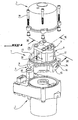
- the figure 1 shows an electric pump unit comprising a gear pump according to the invention, designated by the reference 1 and intended to be mounted on an electric drive motor device 2 and to be covered with a cover 3.
- the pump 1 essentially comprises a base module 5, a pump body 6 and a cover 7.
- the body 6 and the cover 7 are capped by the cover 3 which bears on the base module 5 and is fixed to it by screws 19.
- the hood thus constitutes an outer jacket and forms a low pressure liquid reservoir.
- the basic module is adapted to form the interface between the drive motor 2 and the pump body 6.
- the base module comprises a solid central portion in the form of a base 10 for supporting the pump body 6, surrounded by an outer wall of substantially cylindrical casing 11 which it is secured to a curved side wall 12
- the base 10 and the outer wall 11 delimit between them a recess 13 which is part of the reservoir space of the low pressure hydraulic fluid of the pump enclosed by the cover 3.
- the cover rests on an outer shoulder of the cylindrical wall 11.
- the base module 5 comprises at the level of the curved wall 12 of the pump body 6 a lateral end 14 in the end face 15 which opens the outlet port 16 of the high-pressure liquid pump.
- the module further comprises protrusions provided with through holes 18 of the screws 19 for fixing the pump to the drive motor device 2.
- the pump body 6 is fixed on the support base 10 by four bolts 20 each passing through a hole 21 formed in the body at an angle thereof to anchor in a corresponding hole 22 of the base 10 of body support.
- the pump body 6 comprises a central housing chamber 24 of the gear device 25 comprising two pinions 26, 27 each provided with helical external toothing 28 and lower bearings 29 and upper 30.
- the pump body 6 further comprises a cavity 32 with a circular cross section extending into a cavity 33 formed in the cover 7.
- the cavity 32 which extends from top to bottom of the body 6, parallel to the axis of this in alignment with a cavity 33 of the lid 7.
- the cavities 32 and 33 are adapted to house a pressure-limiting device 34.
- the working chamber of the pump which houses the two gears 26, 27 between the lower bearings 29 and upper 30 open laterally on the outlet side 36 in a vertical channel 37, that is to say parallel to the axis of the body, which opens into the lower face 38 placed on the base 11, in a notch 39 formed in the upper face of the base and which extends over a predetermined length in it, until- beyond the opening 40 in the laying face 38 of the cavity 32 of the pressure limiter 34.
- This recess 39 communicates through a vertical hole 41 coaxial with the cavity 32 with a horizontal channel 42 whose opening towards the outside is the high pressure liquid outlet port 16.
- the outlet channel 37, the horizontal groove recess 39, the vertical channel 41 and the horizontal channel 42 constitute the high pressure outlet channel of the pump.
- the inlet space that is to say the inlet of the low-pressure liquid of the pump, noted 43, communicates with a vertical inlet channel 44 which is open at the top of the upper face 45 of the body and closed at the bottom, but in communication by a channel 46 somewhat laterally offset outward and open at 47 at the lower laying face 38 with the space 13 of low pressure tank of the pump.
- the pump body 6 furthermore houses a feedback valve 48 mounted in an extension 49 of the output channel section 37 of the gear, which opens in the upper face 45 of the body 6 and is axially aligned with a channel 50. through the lid 7 of the pump.
- the figure 4 further shows that the inlet channel 44 extends upwardly through a channel 51 passing through the cover. If the suction of the pump should be through the lower space 13, this channel 51 will then be closed. We still see on the figure 4 grooves 52 for receiving an O-ring 53 interposed between the pump body 6 and the cover 7 and visible on the Figures 2 and 3 .
- the opening orifice 55 of the pressure relief device 34 is located in the side wall of the pump body 6, at a relatively small distance above the installation face 38 of the body, so that the jet of liquid the limiter could not forcefully hit the hood 3 and produce vibrations therein.
- the orifice 55 communicates with a hole 21 for passing a screw 20 for fastening the body to the base, adjacent to the cavity 32 for accommodating the pressure-limiting device 34, in communication with this cavity via an annular space 56 around the screw 20 and a channel 57 formed in the upper surface 45 of the body and the underside of the lid.
- the orifice 55 has a diameter such that the ejection speed of the fluid is sufficiently low so that the jet of oil does not generate a hissing noise on the cover 3.
- the pressure limiter 34 comprises a piston 59 axially movable in a sleeve 60, the lower portion 61 is screwed into the lower part of the cavity 32 and the upper portion 62 leaves an annular space 63 between it and the cavity, which is in communication with the upper part 64 in which the channel 57 is connected to the outlet orifice 55.
- the bushing 60 has in its portion 62 of outside diameter less than the diameter of the cavity 32 a plurality of holes radial 65 that the piston 59 closes in its closed position under the effect of a spring 66 housed in the upper portion 64 of the cavity 32 and that it opens when the pressure in the outlet channel section 39 of the pump exceeds a predetermined limit value.
- the refill valve 48 comprises a ball 68 pushed by a spring 69 disposed in the extension 49 of the section of the outlet channel 37 against a seat 70 formed by the lower edge of the hole 50 of the cover 7 also in axial alignment with the section of channel 37.
- the modular structure of the gear pump according to the invention which has just been described, highlights an essential characteristic of the invention, which lies in the configuration of the flow path of the high pressure fluid as a means of damping of the pulsations in the high pressure liquid produced by the gearing, which preserves the advantage of the reduction of the pressure pulsations, which the helical gears provide, with respect to the spur gears.
- the flow path of the high pressure fluid according to the invention is able to fulfill its function of means for reducing the pressure pulsations by means of variations of its section on its length and elbows at 90 °.
- the outlet channel formed by the sections 37, 39, 41 and 42 comprises three 90 ° elbows respectively formed by the junction of the channel sections 37, 39, the junction of the channels 39, 41 and the junction of the channels 41 and 42. These elbows can break the jet of oil that is the hydraulic fluid.
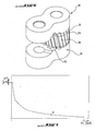
- an increase in volume ⁇ V causes a decrease in pressure ⁇ P, which, because of the negative sign means that it is a decrease in pressure.
- an increase in cross-section results in an increase in ⁇ V and causes a reduction in pressure.
- the pressure pulsations ⁇ P decrease with an increase in pressure losses in a channel.
- PC - ⁇ D • ⁇ ⁇ V 2 2 •
- PC the linear pressure drop in Pa
- ⁇ the pressure loss coefficient
- ⁇ the density of the water in kg / m 3
- V the flow velocity in m / s
- D the diameter hydraulic tube in m
- L the length of the tube in m.
- Another measure to reduce the pressure pulsations produced by the gear is to make the teeth of the gears so that the recovery ratio is between 0.8 and 1.2 and preferably equal to 1.
- the figure 6 illustrates the pressure cavities noted 70 made in the same manner in the lower bearing 29 and the upper bearing 30. These cavities are formed in the form of grooves perpendicular to the plane passing through the axes of the gables, of an appropriate depth and length in the gear meshing area.
Landscapes
- Engineering & Computer Science (AREA)
- Mechanical Engineering (AREA)
- General Engineering & Computer Science (AREA)
- Details And Applications Of Rotary Liquid Pumps (AREA)
- Rotary Pumps (AREA)
Claims (11)
- Hydraulische Pumpe, insbesondere einer Elektropumpeneinheit, speziell für die Servolenkung eines Kraftfahrzeugs, der Zahnradbauart, die einen Pumpenkörper (6) umfasst, der mit einer Aufnahmekammer (24) von zwei Zahnritzeln (26, 27) ausgestattet ist, die ineinander eingreifen, einer Ansaugöffnung (50) für eine Niederdruckflüssigkeit, einer Ausgangsöffnung (16) für die Hochdruckflüssigkeit und einem Durchflussweg der Hochdruckflüssigkeit, der den Ausgang der Aufnahmekammer (24) der Pumpe mit dem Ausgang (16) der Pumpe verbindet und ein Mittel zur Dämpfung der Pulsationen der Hochdruckflüssigkeit umfasst, dadurch gekennzeichnet, dass der Durchflussweg, der das Dämpfungsmittel umfasst, in Form eines Kanals ausgebildet ist, der eine Abfolge einer Mehrzahl gerader Kanalteilstücke (37, 39, 41, 42) umfasst, die an ihren jeweiligen Verbindungen Knie bilden und deren Querschnitte entlang des Kanals variieren, wobei die Variation der Querschnitte und der Knie die Pulsations-Dämpfungsmittel darstellen.
- Hydraulikpumpe nach Anspruch 1, dadurch gekennzeichnet, dass ein Kanalteilstück eine Länge und einen Querschnitt als Funktion der Lastverluste und der Pulsationsdämpfung aufweist.
- Hydraulikpumpe nach Anspruch 1, dadurch gekennzeichnet, dass ein Kanalteilstück eine Länge und einen Querschnitt aufweist, die derart ausgewählt sind, dass Lastverluste entstehen, die in dem Schema angesiedelt sind, das die Pulsationen in Abhängigkeit von den Lastverlusten im Bereich der schwachen Pulsationen repräsentiert, wo die Lastverluste noch begrenzt sind.
- Hydraulikpumpe nach Anspruch 1, dadurch gekennzeichnet, dass der Durchflussweg der Hochdruckflüssigkeit drei Knie umfasst, die etwa in 90 Grad ausgerichtet sind.
- Hydraulikpumpe nach einem der Ansprüche 1 bis 4, dadurch gekennzeichnet, dass die Zahnritzel (26, 27) schraubenartige Zahnritzel sind, die eine Sprungüberdeckung zwischen 0,8 und 1,2 inklusive haben, vorzugsweise von 1.
- Hydraulikpumpe nach einem der Ansprüche 1 bis 5, dadurch gekennzeichnet, dass die Pumpe durch Übereinanderstellen in ihrer axialen Richtung eines Basismoduls (5) und eines Pumpenkörpers (6) gebildet wird, wobei der Durchflussweg der Hochdruckflüssigkeit Kanalteilstücke (37, 41) parallel zur Achse der Pumpe und Teilstücke (39, 42) senkrecht zu dieser Achse umfasst.
- Hydraulikpumpe nach Anspruch 6, dadurch gekennzeichnet, dass die senkrechten Kanalteilstücke (39, 42) in das Basismodul eingearbeitet und durch einen vorgenannten parallelen Kanal (41) verbunden sind.
- Hydraulikpumpe nach einem der Ansprüche 3 bis 7, dadurch gekennzeichnet, dass der Durchflussweg der Hochdruckflüssigkeit derart konfiguriert ist, dass sein Querschnitt in Richtung der Hochdruck-Ausgangsöffnung (16) zunimmt.
- Hydraulikpumpe nach einem der Ansprüche 1 bis 8, dadurch gekennzeichnet, dass das Basismodul (5) einen Sockel (10) umfasst, der den Pumpenkörper (6) trägt und von einer äußeren umhüllenden Wand (11) umgeben ist, und dadurch, dass ein Raum für Niederdruckflüssigkeit (13) zwischen der umhüllenden Wand (11) und dem Sockel (10) begrenzt ist, wobei der Pumpenkörper (6) mit einer Kappe (7) abgedeckt ist, die auf der umhüllenden Wand (11) des Basismoduls (5) ruht und einen Mantel für den Niederdruckflüssigkeitsbehälter darstellt.
- Hydraulikpumpe nach Anspruch 9, dadurch gekennzeichnet, dass sie eine Druckmindervorrichtung (34) umfasst, deren Ausgangsöffnung (55) in einem geringen Abstand über der Fläche der umhüllenden Wand (11) angeordnet ist, auf der die Kappe (3) ruht, um zu verhindern, dass der Flüssigkeitsstrahl, der aus der Druckmindervorrichtung austritt, in der Kappe Vibrationen erzeugt.
- Hydraulikpumpe nach Anspruch 10, dadurch gekennzeichnet, dass der Hohlraum (32) zur Aufnahme des Druckminderers (34) mit einem ringförmigen Raum (56) kommuniziert, der in einem Durchgangsloch (21) einer Schraube (20) zur Befestigung des Pumpenkörpers (6) auf dem Basismodul (5) um diese Schraube begrenzt ist, das mit der Ausgangsöffnung (55) der Druckmindervorrichtung verbunden ist.
Applications Claiming Priority (1)
| Application Number | Priority Date | Filing Date | Title |
|---|---|---|---|
| FR0601384A FR2897399B1 (fr) | 2006-02-16 | 2006-02-16 | Pompe hydraulique, notamment de groupe electro-pompe en particulier pour la direction assistee de vehicule automobile |
Publications (2)
| Publication Number | Publication Date |
|---|---|
| EP1820969A1 EP1820969A1 (de) | 2007-08-22 |
| EP1820969B1 true EP1820969B1 (de) | 2010-10-20 |
Family
ID=37192285
Family Applications (1)
| Application Number | Title | Priority Date | Filing Date |
|---|---|---|---|
| EP20070290188 Ceased EP1820969B1 (de) | 2006-02-16 | 2007-02-14 | Hydraulische Pumpe, insbesondere einer Elektropumpeneinheit, speziell für die Servolenkung eines Kraftfahrzeugs |
Country Status (3)
| Country | Link |
|---|---|
| EP (1) | EP1820969B1 (de) |
| DE (1) | DE602007009883D1 (de) |
| FR (1) | FR2897399B1 (de) |
Families Citing this family (3)
| Publication number | Priority date | Publication date | Assignee | Title |
|---|---|---|---|---|
| FR2922274B1 (fr) * | 2007-10-12 | 2009-12-04 | Jtekt Hpi | Agencement de pompe hydraulique a engrenage externe et pourvue de moyens d'isolation acoustique |
| PL3127779T3 (pl) * | 2014-03-31 | 2019-10-31 | Guangdong Huachan Research Institute Of Intelligent Transp System Co Ltd | Silnik wspomagania układu kierowniczego |
| CN110318996B (zh) * | 2018-03-29 | 2024-09-06 | 佛山市顺德区美的饮水机制造有限公司 | 泵壳、连接器、泵体、增压泵和净水机 |
Family Cites Families (6)
| Publication number | Priority date | Publication date | Assignee | Title |
|---|---|---|---|---|
| GB2036873B (en) * | 1978-12-01 | 1983-02-09 | South Western Ind Res | Silencing fluid pumps and motors |
| DE19524965A1 (de) * | 1995-07-08 | 1997-01-09 | Bosch Gmbh Robert | Zahnradmaschine (Pumpe oder Motor) |
| GB2336876B (en) * | 1998-04-29 | 2001-06-27 | Sauer Sundstrand Ltd | Separated helical gear pump |
| JP3773370B2 (ja) * | 1998-09-18 | 2006-05-10 | 株式会社ジェイテクト | 電動ポンプ |
| US6305919B1 (en) * | 1999-08-24 | 2001-10-23 | Visteon Global Technologies, Inc. | Hydraulic pump housing with an integral dampener chamber |
| US6551070B2 (en) * | 2001-08-22 | 2003-04-22 | Micropump, Inc., A Unit Of Idex Corporation | Devices and methods for noise suppression in pumps |
-
2006
- 2006-02-16 FR FR0601384A patent/FR2897399B1/fr not_active Expired - Fee Related
-
2007
- 2007-02-14 EP EP20070290188 patent/EP1820969B1/de not_active Ceased
- 2007-02-14 DE DE200760009883 patent/DE602007009883D1/de active Active
Also Published As
| Publication number | Publication date |
|---|---|
| DE602007009883D1 (de) | 2010-12-02 |
| FR2897399A1 (fr) | 2007-08-17 |
| FR2897399B1 (fr) | 2013-11-15 |
| EP1820969A1 (de) | 2007-08-22 |
Similar Documents
| Publication | Publication Date | Title |
|---|---|---|
| EP3615848B1 (de) | Käfigplanetenträger für eine drehzahlminderungseinheit mit einem planetenradgetriebe | |
| EP1820969B1 (de) | Hydraulische Pumpe, insbesondere einer Elektropumpeneinheit, speziell für die Servolenkung eines Kraftfahrzeugs | |
| WO1999017013A1 (fr) | Pompe a jet comprenant un gicleur de section variable | |
| EP1783371B1 (de) | Elektropumpeneinheit | |
| EP0278824A1 (de) | Hydraulische Antischwingungslager | |
| EP0748939A1 (de) | Elektromotor-Pumpen-Aggregat | |
| FR3041045A1 (fr) | Agencement d'au moins deux dispositifs de pompes hydrauliques | |
| EP0053559B1 (de) | Verteilungseinrichtung, insbesondere für eine Servolenkungsanlage | |
| EP3992425A1 (de) | Modulare pumpe | |
| FR2464391A1 (fr) | Amplificateur de couple hydraulique, notamment pour des dispositifs de direction | |
| EP2273126B1 (de) | Rückschlagventil für automatische Rückführung | |
| EP0537051B1 (de) | Anlage zum Pumpen von Gasen mit Pumpengeschwindigkeitsregelung | |
| CA2636628C (fr) | Dispositif de pompage | |
| EP3049693B1 (de) | Vorrichtung zur reduzierung der winkelgeschwindigkeit | |
| EP0802327A1 (de) | Zahnradpumpe | |
| FR2707198A1 (fr) | Système de lubrification pour un porte-outil. | |
| FR2549909A1 (fr) | Pompe a galets a mouvement peristaltique et rotor pour cette pompe | |
| EP3384180B1 (de) | Untersetzungsgetriebe mit zwei zwischenleitungen für einen turbopropmotor, turbopromotor mit besagtem untersetzungsgetriebe | |
| FR2668238A3 (fr) | Reducteur de pression avec valve inclinee. | |
| EP3645906B1 (de) | Hydraulikpumpe für eine hydraulische verbindungsstelle eines kupplungsmechanismus | |
| FR3129450A1 (fr) | Raccord fluidique en particulier pour boite d’engrenages de turbomachine d’aeronef | |
| EP1327793A1 (de) | Hydraulischer Dämpfer mit verstellbarer Kompensation | |
| EP0683323B1 (de) | Vorlaufrad einer Pumpe für Windschutzscheibenwascher bei Kraftfahrzeugen | |
| EP0344059B1 (de) | Rotierende Zahnradvorrichtung zur Förderung einer Flüssigkeit | |
| FR2602551A3 (fr) | Dispositif pour la lubrification des moteurs de pompes sous-marines |
Legal Events
| Date | Code | Title | Description |
|---|---|---|---|
| PUAI | Public reference made under article 153(3) epc to a published international application that has entered the european phase |
Free format text: ORIGINAL CODE: 0009012 |
|
| AK | Designated contracting states |
Kind code of ref document: A1 Designated state(s): AT BE BG CH CY CZ DE DK EE ES FI FR GB GR HU IE IS IT LI LT LU LV MC NL PL PT RO SE SI SK TR |
|
| AX | Request for extension of the european patent |
Extension state: AL BA HR MK YU |
|
| 17P | Request for examination filed |
Effective date: 20080215 |
|
| 17Q | First examination report despatched |
Effective date: 20080326 |
|
| AKX | Designation fees paid |
Designated state(s): DE FR GB IT |
|
| GRAP | Despatch of communication of intention to grant a patent |
Free format text: ORIGINAL CODE: EPIDOSNIGR1 |
|
| GRAS | Grant fee paid |
Free format text: ORIGINAL CODE: EPIDOSNIGR3 |
|
| GRAA | (expected) grant |
Free format text: ORIGINAL CODE: 0009210 |
|
| AK | Designated contracting states |
Kind code of ref document: B1 Designated state(s): DE FR GB IT |
|
| REG | Reference to a national code |
Ref country code: GB Ref legal event code: FG4D Free format text: NOT ENGLISH |
|
| REF | Corresponds to: |
Ref document number: 602007009883 Country of ref document: DE Date of ref document: 20101202 Kind code of ref document: P |
|
| PLBE | No opposition filed within time limit |
Free format text: ORIGINAL CODE: 0009261 |
|
| STAA | Information on the status of an ep patent application or granted ep patent |
Free format text: STATUS: NO OPPOSITION FILED WITHIN TIME LIMIT |
|
| 26N | No opposition filed |
Effective date: 20110721 |
|
| REG | Reference to a national code |
Ref country code: DE Ref legal event code: R097 Ref document number: 602007009883 Country of ref document: DE Effective date: 20110721 |
|
| REG | Reference to a national code |
Ref country code: FR Ref legal event code: PLFP Year of fee payment: 10 |
|
| REG | Reference to a national code |
Ref country code: FR Ref legal event code: PLFP Year of fee payment: 11 |
|
| REG | Reference to a national code |
Ref country code: FR Ref legal event code: PLFP Year of fee payment: 12 |
|
| PGFP | Annual fee paid to national office [announced via postgrant information from national office to epo] |
Ref country code: DE Payment date: 20240228 Year of fee payment: 18 Ref country code: GB Payment date: 20240221 Year of fee payment: 18 |
|
| PGFP | Annual fee paid to national office [announced via postgrant information from national office to epo] |
Ref country code: IT Payment date: 20240227 Year of fee payment: 18 Ref country code: FR Payment date: 20240219 Year of fee payment: 18 |
|
| REG | Reference to a national code |
Ref country code: DE Ref legal event code: R119 Ref document number: 602007009883 Country of ref document: DE |
|
| GBPC | Gb: european patent ceased through non-payment of renewal fee |
Effective date: 20250214 |
|
| PG25 | Lapsed in a contracting state [announced via postgrant information from national office to epo] |
Ref country code: DE Free format text: LAPSE BECAUSE OF NON-PAYMENT OF DUE FEES Effective date: 20250902 |
|
| PG25 | Lapsed in a contracting state [announced via postgrant information from national office to epo] |
Ref country code: GB Free format text: LAPSE BECAUSE OF NON-PAYMENT OF DUE FEES Effective date: 20250214 |
|
| PG25 | Lapsed in a contracting state [announced via postgrant information from national office to epo] |
Ref country code: IT Free format text: LAPSE BECAUSE OF NON-PAYMENT OF DUE FEES Effective date: 20250214 Ref country code: FR Free format text: LAPSE BECAUSE OF NON-PAYMENT OF DUE FEES Effective date: 20250228 |