EP1818964A2 - Fuse rail with lateral outlet contacts and lateral adapter module - Google Patents
Fuse rail with lateral outlet contacts and lateral adapter module Download PDFInfo
- Publication number
- EP1818964A2 EP1818964A2 EP07101078A EP07101078A EP1818964A2 EP 1818964 A2 EP1818964 A2 EP 1818964A2 EP 07101078 A EP07101078 A EP 07101078A EP 07101078 A EP07101078 A EP 07101078A EP 1818964 A2 EP1818964 A2 EP 1818964A2
- Authority
- EP
- European Patent Office
- Prior art keywords
- contact
- fuse
- strip
- housing
- outgoing
- Prior art date
- Legal status (The legal status is an assumption and is not a legal conclusion. Google has not performed a legal analysis and makes no representation as to the accuracy of the status listed.)
- Granted
Links
- 239000004020 conductor Substances 0.000 claims abstract description 13
- 210000002105 tongue Anatomy 0.000 claims description 33
- 238000003780 insertion Methods 0.000 description 3
- 230000037431 insertion Effects 0.000 description 3
- 238000010276 construction Methods 0.000 description 2
- 230000000694 effects Effects 0.000 description 2
- 238000009434 installation Methods 0.000 description 2
- 230000013228 contact guidance Effects 0.000 description 1
- 230000001419 dependent effect Effects 0.000 description 1
- 238000006073 displacement reaction Methods 0.000 description 1
- 230000001771 impaired effect Effects 0.000 description 1
- 239000011810 insulating material Substances 0.000 description 1
- 238000009413 insulation Methods 0.000 description 1
- 239000002184 metal Substances 0.000 description 1
- 230000004048 modification Effects 0.000 description 1
- 238000012986 modification Methods 0.000 description 1
- 230000005405 multipole Effects 0.000 description 1
- 230000036316 preload Effects 0.000 description 1
- 230000007704 transition Effects 0.000 description 1
Images


Classifications
-
- H—ELECTRICITY
- H01—ELECTRIC ELEMENTS
- H01H—ELECTRIC SWITCHES; RELAYS; SELECTORS; EMERGENCY PROTECTIVE DEVICES
- H01H9/00—Details of switching devices, not covered by groups H01H1/00 - H01H7/00
- H01H9/10—Adaptation for built-in fuses
- H01H9/102—Fuses mounted on or constituting the movable contact parts of the switch
-
- H—ELECTRICITY
- H01—ELECTRIC ELEMENTS
- H01H—ELECTRIC SWITCHES; RELAYS; SELECTORS; EMERGENCY PROTECTIVE DEVICES
- H01H31/00—Air-break switches for high tension without arc-extinguishing or arc-preventing means
- H01H31/02—Details
- H01H31/12—Adaptation for built-in fuse
- H01H31/122—Fuses mounted on, or constituting the movable contact parts of, the switch
-
- H—ELECTRICITY
- H02—GENERATION; CONVERSION OR DISTRIBUTION OF ELECTRIC POWER
- H02B—BOARDS, SUBSTATIONS OR SWITCHING ARRANGEMENTS FOR THE SUPPLY OR DISTRIBUTION OF ELECTRIC POWER
- H02B1/00—Frameworks, boards, panels, desks, casings; Details of substations or switching arrangements
- H02B1/18—Disposition or arrangement of fuses
-
- H—ELECTRICITY
- H01—ELECTRIC ELEMENTS
- H01H—ELECTRIC SWITCHES; RELAYS; SELECTORS; EMERGENCY PROTECTIVE DEVICES
- H01H85/00—Protective devices in which the current flows through a part of fusible material and this current is interrupted by displacement of the fusible material when this current becomes excessive
- H01H85/02—Details
- H01H85/20—Bases for supporting the fuse; Separate parts thereof
- H01H85/205—Electric connections to contacts on the base
- H01H2085/2055—Connections to bus bars in an installation with screw in type fuses or knife blade fuses
-
- H—ELECTRICITY
- H01—ELECTRIC ELEMENTS
- H01H—ELECTRIC SWITCHES; RELAYS; SELECTORS; EMERGENCY PROTECTIVE DEVICES
- H01H85/00—Protective devices in which the current flows through a part of fusible material and this current is interrupted by displacement of the fusible material when this current becomes excessive
- H01H85/54—Protective devices wherein the fuse is carried, held, or retained by an intermediate or auxiliary part removable from the base, or used as sectionalisers
- H01H85/545—Protective devices wherein the fuse is carried, held, or retained by an intermediate or auxiliary part removable from the base, or used as sectionalisers with pivoting fuse carrier
Definitions
- the invention relates to a fuse strip having the features of the preamble of patent claim 1.
- a fuse bar is for example from the DE 100 54 168 known.
- Such fuse strips are preferably designed as two or three poles and are clamped on a group of two or three busbars.
- Such fuse bars contain per conductor a fuse unit, which lies between the relevant conductor of the busbar group on the one hand and a subsequent device in the circuit.
- Such fuse strips are provided with terminals, which are preferably formed in an end region of the strip and serve to connect wiring to the respective switching device.
- a contact element which contacts the associated busbar. This contact element is connected via conductors to one side of the associated fuse element, while the other side of the fuse element is electrically connected to a screw terminal to which a conductor of the relevant switching device or the like can be connected.
- the invention has the object of providing a fuse strip of the type mentioned in such a way that the outgoing contacts allow a direct and preferably screwless connection of outgoing lines.
- a fuse strip to be created which can be optionally equipped with frontal terminals.
- the invention provides a fuse strip, in particular a bridge-shaped fuse strip for direct plugging on a busbar system, in which the outgoing contacts are each formed laterally of the fuse strip. This allows a direct connection of outgoing lines to the side outlet contacts.
- a significant advantage of the fuse strip according to the invention is that the need for known fuse strips within the housing railways omitted to the front terminals, ie the fuse strip total may have a pleasing and shorter shape and in consequence of insulating ribs necessary in the longitudinal direction of the bar running effort to isolate the mutually adjacent conductor guides deleted.
- the side outgoing contacts are equipped with clamping springs, whereby a screwless connection of the outgoing lines is made possible, d. H.
- the outgoing cables need only be plugged into the respective openings for connection to the fuse strip and are locked automatically.
- an additional opening is provided, by means of a tool, the latching between the outgoing contact and outgoing line can be canceled.
- all functionally relevant parts of a pole in the respective pole section i. H. housed within the fuse strip in the region of the respective terminal block 10 or 11 or 12, namely the fuse holder, the incoming and outgoing contacts and the respective outgoing terminal, preferably in the form of a screwless spring clip.
- Each of these pole sections thus forms a subarea in the form of a functional unit.
- the fuse strips can be designed as a bipolar and four-pole embodiments in combination of two such fuse strips.
- the fuse strip according to the invention are provided per outlet contact side of the bar provided terminal blocks containing the outgoing contacts in an easily accessible manner.
- vertically extending, ie perpendicular to the longitudinal axis extending openings for inserting the outgoing lines are provided in the laterally molded terminal blocks per outlet contact and respectively preferably an opening also in a vertical orientation for insertion of a tool, such as a screwdriver for releasing the connection between the outgoing contact and outgoing line.
- the fuse strip is bipolar, but also multi-pole executable.
- the invention further provides a fuse strip having side outgoing contacts, which can be modified if necessary by means of an adapter strip such that end-side terminals can be provided.
- the fuse strip has in one embodiment, the side of the housing in each case a terminal block per pole, wherein in each terminal block a outgoing contact for preferably screwless connection of outgoing lines is included and each outgoing contact via the respective fuse element forms a circuit to the associated contact element for contacting each of a busbar ,
- each terminal block includes a guide for introducing drain lines.
- each terminal block may have a further, preferably slot-shaped opening for the introduction of a tool in the direction of the outgoing contact to release an outgoing line.
- Each output contact preferably includes a contact and a clamping spring, wherein the clamping spring has a spring tongue which is spring-biased against a contact portion of the contact.
- each contact can be provided with an extended contact portion, on which a portion facing away from the contact is formed, which has a contact tongue for receiving the clamping spring, wherein the clamping spring is laterally provided for contact offset.
- the clamping spring is preferably a separate part for contact and has a leg having a slot, such that within the slot, a contact spring tongue of the clamping spring is adjustably arranged and the slot, the contact tongue of the contact receives.
- Each contact preferably includes two mutually approximately parallel, mirror-symmetrical to each other lying contact tongues, wherein the two contact tongues are bordered by a substantially U-shaped spring clip.
- the housing advantageously has a housing lower part, in which recesses for receiving the contacts are formed.
- the fuse strip is formed bipolar and has at least at one end connecting means for receiving a further fuse strip.
- the slots are advantageously provided parallel to the guides and are largely aligned with a V-shaped leg portion of the respective contact tongue.
- Fig. 1 shows a three-pole fuse strip, which consists of a housing 1, preferably made of plastic.
- the housing may be divided into an upper housing part and a lower housing part, which is not shown in Fig. 1 further.
- Within the housing 1 are in the three-pole fuse strip shown in Fig. 1, three levers 2, 3, 4, by the actuation thereof within the housing rotatably mounted securing receptacles are adjustable so that the existing backup in the recordings fuses can be removed or inserted.
- On the underside of the fuse strip are each a clamping foot 6, 7, 8, which is pushed onto a respective busbar, not shown. This principle is known per se.
- Each terminal block 10, 11, 12 has a recess 14, 15, 16, such that the respective Klemmfuß Scheme arranged therein can be displaced over the respective busbar.
- each terminal block 10, 11, 12 is at least one preferably cylindrical opening or guide 18, 19, 20 is formed, which serves to a discharge line preferably displaced vertically downwards and can be inserted into a Giranordndung to be described.
- Next to the opening or guide 18, 19, 20 located per terminal block 10, 11, 12 each have a further preferably slot-shaped opening or guide 22, 23, 24, which serves to solve a once established connection between the contact assembly and the outlet line in case of need by means of a tool.
- Fig. 2 shows a view of the fuse strip corresponding to FIG. 1 from the direction of the arrow in Fig. 1 designated by 25 and shows the clamping feet 6, 7, 8 and a cover plate 26 which z. B. by ratchet teeth 27, 28, 29 is fixed, which engage in a corresponding opening 31, 32, 33, which are each formed in the plate or wall 26.
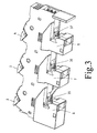
- Fig. 3 shows a view of the fuse strip from below as shown in FIG. 1 and illustrates contact elements 35, 36, 37, which are inserted above the clamping feet 6, 7, 8 in the housing to after placing the fuse strip on the relevant Busbars make electrical contact with the busbars.
- contact elements 35, 36, 37 are formed above the clamping feet 6, 7, 8, to contact the busbars.
- the contact elements 35, 36, 37 are connected via a contact path with one end of the fuse elements inserted into the housing 1, while the other side of the fuse elements is guided via a contact path to a contact arrangement, which is located within the lateral terminal blocks 10, 11, 12 , as explained in more detail below.
- Fig. 4 shows a side view of the fuse strip according to Fig. 2, wherein the wall or plate 26 is removed and thus the Kunststofffiihrung within the housing 1 can be seen.
- Two of the three busbars are indicated in the three-pole fuse strip according to Fig. 4 by the reference numerals 38, 39.
- the contact elements 35, 36, 37 are biased by springs 41, 42, 43 in the direction of the respective busbars 38, 39 in order to ensure a good electrical contact between the contact elements 35 to 37 and the associated busbars 38, 39.
- the circuit runs from the contact element 37 via a contact section 45 to a contact 46, which consists of two substantially parallel, mirror-symmetrical to each other Contact tongues 46a consists, as will be explained in more detail below.
- the contact tongues 46a engage around an end of a securing element 48, the z. B. is provided with a cylindrical conductive element, whereby one side of the fuse element 48 and a fuse is electrically contacted.
- the other end of the fuse or fuse element 48 likewise has, for example, a cylindrically shaped conductor section which is in electrical connection with a further contact 50, wherein the contact 50 corresponding to the contact 46 has two substantially mutually mirror-symmetrical contact tongues 50a, which the Contact the conductive end of the fuse element 48. From the contact 50 of the circuit via a contact portion 52 to the laterally disposed outgoing contact 53rd
- the contacts 46, 48 inserted from the recognizable from Fig. 4 side into the housing in a simple manner or can be used.
- the contacts 46, 50 will be explained in more detail below.
- corresponding recesses are provided in the housing, which ensure that the contacts can be quickly and safely inserted from the side into these recesses and / or ribs or projections and remain slip-proof in the housing.
- the open in Fig. 4 side of the housing is closed by the cover or plate 26, the plate 26 is locked in the manner described with respect to the housing or otherwise secured.
- the contacts 46, 50 are formed substantially identical and preferably identical to each other with respect to the contact tongues 46a, 50a.
- the recesses 54 and 55 for receiving the contacts 46, 50 preferably correspond largely to the shape of the contacts 46, 50 in order to receive these contacts safely and immovably.
- corresponding guide slots or recesses may be provided in the housing.
- the contact portions 45, 52 are formed differently from each other. This will be described in more detail below with reference to section 52.
- the section 45 merely represents a connecting section to the contact 37.
- a spring-loaded latching catch 57 is provided on the right-hand clamping foot 6 in FIG. 4, which is preferably provided with latching teeth through which Spring preload prestressed lever 57a, on the one hand to allow the use of the fuse strip on busbars of different dimensions and on the other hand to ensure a latching against the relevant, not shown in Fig. 4 busbar after placing the fuse strip.
- Fig. 5 shows a perspective view of a contact 50, as it is preferably used in the embodiment of Fig. 4.
- a contact 50 is provided per pole and the circuits are defined per pole, as described above in connection with FIG. 4 with respect to the busbar 39.
- the contact 50 preferably consists of two contact tongues 50a, 50a 'lying essentially mirror-symmetrically to one another. These contact tongues 50a, 50a 'engage around the conductive end of the fuse 48.
- the two contact tongues 50a, 50a' are fixedly connected to one another at a section designated by 50c, 50c 'by a transverse bow 58 and are preferably resiliently connected to one another.
- the two contact tongues 50a, 50a 'each have on their outer side two mutually parallel locking cams 59, 60 which are provided to fix a U-shaped spring 62 encompassing the two contact tongues 50a, 50a'.
- the contact tongue 50a 'in the form of a web 64 narrower in relation to the wall 50c extends beyond the transverse bow 58 downwards and together with a section 65 pointing away from the web 64 forms an approximately L-shaped contact. shaped extension.
- Section 65 is provided with another 90 ° angled portion 66, with the 90 ° angle between the sections 65 and 66 in one direction, such that the portion 66 projects outwardly from the plane of the tongue 50a ', ie, in a direction opposite to the tongue 50a ( Figure 5).
- At the portion 66 is down from an extension 68, which has a smaller width than the portion 66, as is readily apparent from Fig. 5.
- a spring 70 is provided, wherein the spring 70 may alternatively be formed as an integrated part of the contact 50.
- the spring 70 is provided separately from the contact 50, such that a leg 71 of the spring 70 is provided with a slot or approximately rectangular opening 72.
- the leg 71 is at an angle of about 90 °, preferably greater than 90 ° from a base 73 of the spring 70 from.
- a further leg 75 is provided after an approximately U-shaped transition section 74, which is slightly V-shaped according to FIG. 5 and carries at its end a spring tongue 76 which has a width which is slightly smaller than that Width of the slot 72 and which abuts against the contact portion 68 of this pivotally.
- the contact 50 with the spring 70 is designed such that a stripped cable end, i. H. an outgoing line in Fig. 5 from top to bottom with pivoting of the spring tongue 76 in Fig. 5 in the counterclockwise direction between the portion 68 and the spring tongue 76 can be inserted, d. H. a screwless connection of the outgoing cable is possible.
- a retraction of the outgoing line from this engagement relationship is prevented by the action of the spring tongue 76 which abuts obliquely relative to the axis of the outlet line to the outlet line, not shown.
- the outgoing contacts formed by the sections 65, 66, 75, 76, 68, in each case one of the terminal blocks 10, 11, 12, while the pole provided Contact 50 within the housing 1 in Fig. 1 side of a fuse element and from this downwardly extending into the housing 1 is inserted.
- the contact 50 is therefore above the respective outgoing contact.
- the component 50 in electrical contact with the respective fuse is arranged approximately centrally within the upper housing part of the fuse strip is, while the portion in the form of the spring 70 together with the sections 65, 66, 68 laterally outwardly offset to the contact 50, with the result that the associated outlet line laterally offset from the contact 50 in the outgoing contact in the form of sections 65, 66, 68, 76 can be introduced.
- the actual outgoing contact, formed by the sections 65, 66, 68, 73, 74, 76 is thus located in a plane which is offset parallel and laterally outwards to the level of the respective fuse.
- the outgoing contact is by this construction laterally in the terminal blocks 10, 11, 12, that is offset outwardly relative to the housing 1, arranged.
- the lateral design of the guides 18, 19, 20 to the outgoing contacts with clamping spring 70 is inventively possible in that the spring contact 70 is provided laterally offset relative to the located in the housing 1 and in the upper housing part contact 50.
- a curved tab 78 is provided which protrudes from the surface of the portion 64, 65 in the direction of the plane in which the spring 70 is provided.
- the tab 78 in the illustrated embodiment is preferably S-shaped and serves as a stop for the base 73.
- the entire contact 50, including spring 70, after assembly, is shown in the manner shown in FIG Housing 1 inserted into the recesses provided there, and that per intended pole.
- the contact 50 and the spring 70 are made of metal or a conductive material, while the housing itself completely or at least partially made of plastic, d. H. made of insulating material.
- the use of the contact arrangements preferably described in connection with FIG. 5 thus enables a direct connection of the outgoing lines directly adjacent to the security elements present within the housing 1, so that in such fuse bars customary wiring or the installation of contact paths of the relevant fuse holder accounts for up to a given end face of the bar.
- the fuse strips can be made very narrow and compact at least in the upper region of the housing 1.
- the laterally molded, the outgoing contacts receiving terminal blocks 10, 11, 12 ensure a very good insulation and also prevent leakage currents between the individual, adjacent outgoing contacts due to the distancing of the individual terminal blocks 10, 11, 12 to each other in the longitudinal or axial direction of the bar.
- the height of the terminal blocks 10, 11, 12 is selected such that the inlet openings of the guides 18, 19, 20 are at a predetermined distance to the top of the housing 1 and thus outgoing lines can also be laid in parallel and in the axial direction to the housing top 1, without thereby the handling of the levers 2, 3, 4 is impaired by the outgoing lines in any way.
- the housing 1 consists of an upper housing part and a lower housing part, wherein the housing lower part of the designated in Fig. 2 1a section is meant, in which the individual contact arrangements can be introduced while the upper housing part, the plate 26 to understand is.
- the housing lower part 1a rotated by 90 ° with respect to FIG. 2 rearwardly placed on a mounting surface, after which the individual contact arrangements are introduced including the lever 2, 3, 4, before the plate or wall 26 is placed as the upper housing part and through the described latching devices 27, 31 are fixedly connected to the housing lower part 1a or mounted together in some other way.
- the housing 1 is closed at the end by a cover 80.
- FIG. 6 shows two two-pole fuse strips which have a structure substantially as described with reference to FIGS. 1 to 5. Identical parts are provided with the same reference numerals as in Figures 1 to 5.
- connection blocks for the outgoing contacts are provided at the same distance from each other.
- the main advantage of the fuse strip described in connection with FIG. 6 is thus that either two-pole or four-pole fuse strips can be assembled from identical elements and the connection of the outgoing lines can be made screwless by inserting the outgoing lines into the outgoing contacts of the terminal blocks. It can thus achieve a very fast installation of the entire fuse strips in conjunction with the associated switching devices.
- Fig. 7 shows a plan view of a further embodiment of the invention on the basis of the fuse strip, as described in connection with Fig. 1 to 5.
- lateral connection blocks 10, 11, 12 are provided, which serve in the embodiment according to FIGS. 1 to 5, preferably to insert drain lines preferably screwless in the associated outgoing contacts with clamping springs.
- the embodiment according to FIGS. 7 to 9 aims at a modification of the fuse strip to the effect that, if necessary, end-side connection terminals can be used by using the same fuse strip.
- the present invention provides for contacting the lateral terminal blocks with an adapter strip 90, the adapter strip 90 having at one end a module 91 for screw terminals or the like.
- Fig. 7 shows the fuse strip according to Fig. 1 to 5 with an additional, laterally applied adapter strip 90 and the front side of the fuse strip module present 91 for screw terminals.
- the adapter strip 90 has a width transverse to the longitudinal axis, which corresponds to the width of the terminal blocks 10, 11, 12, also viewed transversely to the longitudinal axis corresponds.
- To attach the Adapter strip 90 serve guide members 93, 94, which engage in corresponding counter-guides 95, 96 on the housing side.
- each adapter bar 90 is equipped with pins 97, 98, 99, which in each case strive downwards from the adapter bar 90 and serve to insert into the guides 18, 19, 20 of the terminal blocks to make an electrical connection with the output terminals of the fuse strip.
- the module 91 is integrally formed on one end of the adapter strip 90 approximately perpendicularly laterally therefrom.
- the adapter strip 90 itself can in various ways have connection conductors 101, 102, 103 which are guided by the connection pins 97, 98, 99 in the direction of the connection module 91.
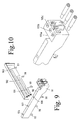
- Fig. 10 shows an example of how these connecting portions 101, 102, 103 may be formed.
- the adapter strip 90 is equipped according to FIG. 10 with integrated strip conductors which are fixedly formed in the adapter strip 90 or, for example, in the form of a printed circuit with pins 97, 98, 99, so that the strip conductors 101, 102, 103 in a printed circuit board or the like are integrated and the circuit board is frontally connected to the connection module 91 mechanically and electrically.
- connection module 91 The screw terminals 105a, b, c of the connection module 91 are conventional and therefore need not be explained in detail.
- each adapter strip is provided with slots 106, 107, 108, which are formed slightly vertically offset from the pins 97 to 99 and are guided past the conductors or connections 101, 102, 103 to a once patch adapter bar 90 against the fuse block or the terminal blocks, similar, as explained in connection with the actuating slots 22, 23, 24 (Fig. 1).
- the slots 106, 107, 108 must in this embodiment be aligned with the slots 22, 23, 24 to allow access by means of a tool to the spring tongue 76 and the actuating portion 75, respectively.
- the slots 106, 107, 108 may be replaced by slots 110, 111, 112 formed laterally in the wall of the respective terminal block 10, 11, 12. If this end is inserted into one of the slots 110, 111, 112 (FIG. 11) with the aid of a tool, for example a screwdriver, the clamping effect between the respective contact pin 97 to 99 can be canceled, so that the module 90 can be lifted off by means of a screwdriver or the like, the spring tongue 76 (Fig. 9) is pivoted counterclockwise and releases the associated contact pin.
Abstract
Description
Die Erfindung betrifft eine Sicherungsleiste mit den Merkmalen des Oberbegriffs des Patentanspruchs 1.The invention relates to a fuse strip having the features of the preamble of patent claim 1.
Eine Sicherungsleiste ist beispielsweise aus der
Der Erfindung liegt die Aufgabe zugrunde, eine Sicherungsleiste der eingangs genannten Art so auszubilden, dass die Abgangskontakte ein direktes und vorzugsweise schraubenloses Anschließen von Abgangsleitungen ermöglichen.The invention has the object of providing a fuse strip of the type mentioned in such a way that the outgoing contacts allow a direct and preferably screwless connection of outgoing lines.
Weiterhin soll eine Sicherungsleiste geschaffen werden, die optional mit stirnseitigen Anschlussklemmen ausgerüstet werden kann.Furthermore, a fuse strip to be created, which can be optionally equipped with frontal terminals.
Diese Aufgabe wird erfindungsgemäß durch die im Patentanspruch 1 angegebenen Merkmale gelöst.This object is achieved by the features specified in claim 1.
Weitere Ausgestaltungen der Erfindung ergeben sich aus den Unteransprüchen.Further embodiments of the invention will become apparent from the dependent claims.
Die Erfindung schafft eine Sicherungsleiste, insbesondere eine brückenförmige Sicherungsleiste zum direkten Aufstecken auf ein Stromschienensystem, bei dem die Abgangskontakte jeweils seitlich der Sicherungsleiste ausgebildet sind. Damit ist ein direktes Anschließen von Abgangsleitungen an den seitlichen Abgangskontakten möglich.
Ein wesentlicher Vorteil bei der erfindungsgemäßen Sicherungsleiste besteht darin, dass die üblicherweise bei bekannten Sicherungsleisten innerhalb des Gehäuses notwendigen Leitungsbahnen zu den stirnseitigen Anschlussklemmen entfallen, d. h. die Sicherungsleiste insgesamt kann eine gefälligere und kürzere Form aufweisen und der in Folge von isolierenden Rippen notwendige in Längsrichtung der Leiste verlaufende Aufwand zur Isolierung der zueinander benachbarten Leiterführungen entfällt.The invention provides a fuse strip, in particular a bridge-shaped fuse strip for direct plugging on a busbar system, in which the outgoing contacts are each formed laterally of the fuse strip. This allows a direct connection of outgoing lines to the side outlet contacts.
A significant advantage of the fuse strip according to the invention is that the need for known fuse strips within the housing railways omitted to the front terminals, ie the fuse strip total may have a pleasing and shorter shape and in consequence of insulating ribs necessary in the longitudinal direction of the bar running effort to isolate the mutually adjacent conductor guides deleted.
Gemäß einer bevorzugten Ausführungsform sind die seitlichen Abgangskontakte mit Klemmfedern ausgerüstet, wodurch ein schraubenloses Anschließen der Abgangsleitungen ermöglicht wird, d. h. die Abgangsleitungen brauchen zum Anschluss an die Sicherungsleiste nur in die jeweiligen Öffnungen eingesteckt werden und werden automatisch verrastet. Zum Lösen der Abgangsleitungen ist eine zusätzliche Öffnung vorgesehen, durch die mittels eines Werkzeuges die Verrasterung zwischen Abgangskontakt und Abgangsleitung aufgehoben werden kann.According to a preferred embodiment, the side outgoing contacts are equipped with clamping springs, whereby a screwless connection of the outgoing lines is made possible, d. H. The outgoing cables need only be plugged into the respective openings for connection to the fuse strip and are locked automatically. To release the outgoing lines, an additional opening is provided, by means of a tool, the latching between the outgoing contact and outgoing line can be canceled.
Gemäß vorliegender Erfindung sind alle funktionsrelevanten Teile eines Poles in dem jeweiligen Polabschnitt, d. h. innerhalb der Sicherungsleiste im Bereich des jeweiligen Anschlussblocks 10 bzw. 11 bzw. 12 untergebracht, nämlich die Sicherungsaufnahme, die Zu- und Abgangskontakte und die jeweilige Abgangsklemme, vorzugsweise in Form einer schraubenlosen Federklemme. Jeder dieser Polabschnitte bildet also einen Teilbereich in Form einer funktionsfähigen Einheit. Auf diese Weise können die Sicherungsleisten als zweipolige und bei Kombination von zwei derartigen Sicherungsleisten vierpolige Ausführungsformen gestaltet werden.According to the present invention, all functionally relevant parts of a pole in the respective pole section, i. H. housed within the fuse strip in the region of the
Bei der erfindungsgemäßen Sicherungsleiste sind pro Abgangskontakt seitlich zur Leiste vorgesehene Anschlussblöcke ausgebildet, welche die Abgangskontakte in leicht zugängiger Weise enthalten. Bei einer bevorzugten Ausführungsform sind in den seitlich angeformten Anschlussblöcken pro Abgangskontakt vertikal verlaufende, d. h. senkrecht zur Längsachse verlaufende Öffnungen zum Einführen der Abgangsleitungen vorgesehen sowie jeweils vorzugsweise eine Öffnung ebenfalls in vertikaler Ausrichtung zur Einführung eines Werkzeugs, beispielsweise Schraubenziehers zum Lösen der Verbindung zwischen Abgangskontakt und Abgangsleitung.In the fuse strip according to the invention are provided per outlet contact side of the bar provided terminal blocks containing the outgoing contacts in an easily accessible manner. In a preferred embodiment, vertically extending, ie perpendicular to the longitudinal axis extending openings for inserting the outgoing lines are provided in the laterally molded terminal blocks per outlet contact and respectively preferably an opening also in a vertical orientation for insertion of a tool, such as a screwdriver for releasing the connection between the outgoing contact and outgoing line.
Die Sicherungsleiste ist zweipolig, jedoch aber auch mehrpolig ausführbar.The fuse strip is bipolar, but also multi-pole executable.
Die Erfindung schafft weiterhin eine Sicherungsleiste, die seitliche Abgangskontakte hat, welche im Bedarfsfall mittels einer Adapterleiste derart modifiziert werden kann, dass stirnseitige Anschlussklemmen bereitgestellt werden können.The invention further provides a fuse strip having side outgoing contacts, which can be modified if necessary by means of an adapter strip such that end-side terminals can be provided.
Die Sicherungsleiste weist bei einer Ausführungsform seitlich des Gehäuses jeweils einen Anschlussblock je Pol auf, wobei in jedem Anschlussblock ein Abgangskontakt zum vorzugsweise schraubenlosen Anschließen von Abgangsleitungen enthalten ist und wobei jeder Abgangskontakt über das jeweilige Sicherungselement einen Stromkreis zum zugehörigen Kontaktelement für die Kontaktierung jeweils einer Stromschiene bildet.The fuse strip has in one embodiment, the side of the housing in each case a terminal block per pole, wherein in each terminal block a outgoing contact for preferably screwless connection of outgoing lines is included and each outgoing contact via the respective fuse element forms a circuit to the associated contact element for contacting each of a busbar ,
Bei einer weiteren Ausführungsform beinhaltet jeder Anschlussblock einer Führung zum Einführen von Abgangsleitungen.In another embodiment, each terminal block includes a guide for introducing drain lines.
Weiterhin kann jeder Anschlussblock eine weitere, vorzugsweise schlitzförmige Öffnung aufweisen zur Einführung eines Werkzeuges in Richtung auf den Abgangskontakt zur Freigabe einer Abgangsleitung.Furthermore, each terminal block may have a further, preferably slot-shaped opening for the introduction of a tool in the direction of the outgoing contact to release an outgoing line.
Die Führungen sind vorzugsweise im Wesentlichen senkrecht zur Längsachse der Sicherungsleiste ausgebildet. Jeder Abgangskontakt beinhaltet vorzugsweise einen Kontakt und eine Klemmfeder, wobei die Klemmfeder eine Federzunge aufweist, die unter Federvorspannung gegen einen Kontaktabschnitt des Kontaktes steht. Dabei kann jeder Kontakt mit einem verlängerten Kontaktabschnitt versehen sein, an dem ein vom Kontakt weg weisender Abschnitt ausgebildet ist, welcher eine Kontaktzunge zur Aufnahme der Klemmfeder aufweist, wobei die Klemmfeder seitlich zum Kontakt versetzt vorgesehen ist.The guides are preferably formed substantially perpendicular to the longitudinal axis of the fuse strip. Each output contact preferably includes a contact and a clamping spring, wherein the clamping spring has a spring tongue which is spring-biased against a contact portion of the contact. In this case, each contact can be provided with an extended contact portion, on which a portion facing away from the contact is formed, which has a contact tongue for receiving the clamping spring, wherein the clamping spring is laterally provided for contact offset.
Die Klemmfeder ist vorzugsweise ein zum Kontakt separates Teil und weist einen Schenkel mit einem Schlitz aufweist, derart, dass innerhalb des Schlitzes eine Kontaktfederzunge der Klemmfeder verstellbar angeordnet ist und der Schlitz die Kontaktzunge des Kontaktes aufnimmt. Jeder Kontakt beinhaltet vorzugsweise zwei zueinander etwa parallele, spiegelsymmetrisch zueinander liegende Kontaktzungen, wobei die beiden Kontaktzunge durch eine im Wesentlichen U-förmige Federklammer eingefasst sind.The clamping spring is preferably a separate part for contact and has a leg having a slot, such that within the slot, a contact spring tongue of the clamping spring is adjustably arranged and the slot, the contact tongue of the contact receives. Each contact preferably includes two mutually approximately parallel, mirror-symmetrical to each other lying contact tongues, wherein the two contact tongues are bordered by a substantially U-shaped spring clip.
Das Gehäuse weist vorteilhafterweise ein Gehäuseunterteil auf, in welchem Aussparungen zur Aufnahme der Kontakte ausgebildet sind.The housing advantageously has a housing lower part, in which recesses for receiving the contacts are formed.
Bei einer weiteren Ausgestaltung ist die Sicherungsleiste zweipolig ausgebildet und besitzt zumindest an einer Stirnseite Verbindungsmittel zur Aufnahme einer weiteren Sicherungsleiste.In a further embodiment, the fuse strip is formed bipolar and has at least at one end connecting means for receiving a further fuse strip.
Die Schlitze sind vorteilhaft parallel zu den Führungen vorgesehen und fluchten weitgehend zu einem V-förmigen Schenkelabschnitt der jeweiligen Kontaktzunge.The slots are advantageously provided parallel to the guides and are largely aligned with a V-shaped leg portion of the respective contact tongue.
Im Folgenden wird eine bevorzugte Ausführungsform anhand der Zeichnungen zur Erläuterung weiterer Merkmale beschrieben. Es zeigen:
- Fig. 1
- eine Perspektivansicht der erfindungsgemäßen Sicherungsleiste von der Seite mit den Anschlussblöcken,
- Fig. 2
- eine Ansicht der Sicherungsleiste gemäß Fig. 1 bei gegenüber Fig. 1 um 180° gedrehter Sicherungsleiste,
- Fig. 3
- eine Perspektivansicht der Sicherungsleiste von unten entsprechend Fig. 1,
- Fig. 4
- eine Darstellung der Sicherungsleiste entsprechend Fig. 2 mit entfernten Seitenwänden zur Darstellung der Kontaktführung,
- Fig. 5
- eine Perspektivansicht zur Darstellung des Abgangkontaktes zusammen mit dem zugehörigen Kontaktelement und
- Fig. 6
- eine schematische Darstellung von zwei zweipoligen Sicherungsleisten
- Fig. 7
- veranschaulicht eine bevorzugte Ausführungsform einer Sicherungsleiste mit im Wesentlichen demjenigen Aufbau, wie er unter Bezugnahme auf Fig. 1 bis 5 beschrieben ist.
- Fig. 8
- ist eine Ansicht der Stirnseite der Sicherungsleiste, aus Richtung des Pfeiles A in Fig. 7 gesehen,
- Fig. 9
- zeigt eine Perspektivansicht einer Adapterleiste,
- Fig. 10
- eine Seitenansicht einer bevorzugten Ausführungsform der Adapterleiste nach Fig. 9, und
- Fig. 11
- eine gegenüber Fig. 1 abgewandelte Ausführungsform
- Fig. 1
- a perspective view of the fuse strip according to the invention from the side with the terminal blocks,
- Fig. 2
- 1 at 180 ° rotated with respect to FIG. 1 fuse strip,
- Fig. 3
- a perspective view of the fuse strip from below corresponding to FIG. 1,
- Fig. 4
- 2 shows an illustration of the fuse strip according to FIG. 2 with the sidewalls removed to show the contact guidance;
- Fig. 5
- a perspective view illustrating the outgoing contact together with the associated contact element and
- Fig. 6
- a schematic representation of two bipolar fuse strips
- Fig. 7
- FIG. 1 illustrates a preferred embodiment of a fuse strip having substantially the structure described with reference to FIGS. 1-5.
- Fig. 8
- is a view of the front side of the fuse strip, seen from the direction of arrow A in Fig. 7,
- Fig. 9
- shows a perspective view of an adapter strip,
- Fig. 10
- a side view of a preferred embodiment of the adapter strip of FIG. 9, and
- Fig. 11
- a comparison with FIG. 1 modified embodiment
Fig. 1 zeigt eine dreipolige Sicherungsleiste, die aus einem Gehäuse 1 besteht, vorzugsweise aus Kunststoff. Das Gehäuse kann in ein Gehäuseoberteil und eine Gehäuseunterteil aufgegliedert sein, was in Fig. 1 nicht weiter dargestellt ist. Innerhalb des Gehäuses 1 befinden sich bei der in Fig. 1 gezeigten dreipoligen Sicherungsleiste drei Hebel 2, 3, 4, durch deren Betätigung innerhalb des Gehäuses drehbar gelagerte Sicherungsaufnahmen derart verstellbar sind, dass die in den Sicherungsaufnahmen vorhandenen Sicherungen entnommen bzw. eingelegt werden können. An der Unterseite der Sicherungsleiste befinden sich jeweils ein Klemmfuß 6, 7, 8, der auf jeweils eine nicht dargestellte Stromschiene aufgeschoben wird. Dieses Prinzip ist an sich bekannt.Fig. 1 shows a three-pole fuse strip, which consists of a housing 1, preferably made of plastic. The housing may be divided into an upper housing part and a lower housing part, which is not shown in Fig. 1 further. Within the housing 1 are in the three-pole fuse strip shown in Fig. 1, three
Seitlich der Sicherungsleiste sind Anschlussblöcke 10, 11, 12 vorgesehen, die den jeweiligen Klemmfuß 6, 7, 8 teilweise integriert aufnehmen, wobei die Anschlussblöcke 10, 11, 12 in Längsrichtung der Sicherungsleiste zueinander beabstandet bzw. getrennt sind. Jeder Anschlussblock 10, 11, 12 weist eine Aussparung 14, 15, 16 auf, derart, dass der betreffende, darin angeordnete Klemmfußbereich über die jeweilige Stromschiene verlagert werden kann.Side of the fuse strip connection blocks 10, 11, 12 are provided, which receive the
Innerhalb jedes Anschlussblocks 10, 11, 12 ist zumindest eine vorzugsweise zylindrische Öffnung oder Führung 18, 19, 20 ausgebildet, die dazu dient, dass eine Abgangsleitung vorzugsweise vertikal nach unten verlagert und in eine noch zu beschreibende Kontaktanordndung eingeschoben werden kann. Neben der Öffnung oder Führung 18, 19, 20 befindet sich pro Anschlussblock 10, 11, 12 jeweils eine weitere vorzugsweise schlitzförmige Öffnung oder Führung 22, 23, 24, die dazu dient, eine einmal hergestellte Verbindung zwischen der Kontaktanordnung und der Abgangsleitung im Bedarfsfalle mittels eines Werkzeuges zu lösen.Within each
Fig. 2 zeigt eine Ansicht der Sicherungsleiste entsprechend Fig. 1 aus Richtung des in Fig. 1 mit 25 bezeichneten Pfeiles und zeigt die Klemmfüße 6, 7, 8 sowie eine Abschlussplatte 26, die am Gehäuseoberteil z. B. durch Rastzähne 27, 28, 29 fixiert ist, welche in eine entsprechende Öffnung 31, 32, 33 eingreifen, die jeweils in der Platte oder Wand 26 ausgebildet sind.Fig. 2 shows a view of the fuse strip corresponding to FIG. 1 from the direction of the arrow in Fig. 1 designated by 25 and shows the clamping
Fig. 3 zeigt eine Ansicht der Sicherungsleiste von unten entsprechend der Darstellung nach Fig. 1 und veranschaulicht Kontaktelemente 35, 36, 37, die oberhalb der Klemmfüße 6, 7, 8 in das Gehäuse eingesetzt sind, um nach dem Aufsetzen der Sicherungsleiste auf die betreffenden Stromschienen einen elektrischen Kontakt gegenüber den Stromschienen herzustellen.Fig. 3 shows a view of the fuse strip from below as shown in FIG. 1 and illustrates
Aus der vorstehenden Beschreibung geht hervor, dass an der Unterseite des Gehäuses 1 Kontaktelemente 35, 36, 37 oberhalb der Klemmfüße 6, 7, 8 ausgebildet sind, um die Stromschienen zu kontaktieren. Die Kontaktelemente 35, 36, 37 sind über einen Kontaktpfad mit einem Ende der in das Gehäuse 1 eingesetzten Sicherungselemente verbunden, während die andere Seite der Sicherungselemente über einen Kontaktweg zu einer Kontaktanordnung geführt ist, die sich innerhalb der seitlichen Anschlussblöcke 10, 11, 12 befindet, wie dies nachfolgend näher erläutert wird.From the above description it is apparent that at the bottom of the housing 1
Fig. 4 zeigt eine Seitenansicht der Sicherungsleiste entsprechend Fig. 2, wobei die Wand oder Platte 26 entfernt ist und damit die Kontaktfiihrung innerhalb des Gehäuses 1 erkennbar ist. Zwei der drei Stromschienen sind bei der dreipoligen Sicherungsleiste nach Fig. 4 durch die Bezugszeichen 38, 39 angedeutet. Die Kontaktelemente 35, 36, 37 sind durch Federn 41, 42, 43 in Richtung auf die betreffenden Stromschienen 38, 39 vorgespannt, um einen guten elektrischen Kontakt zwischen den Kontaktelementen 35 bis 37 und den zugehörigen Stromschienen 38, 39 zu gewährleisten. Hinsichtlich des Kontaktelementes 37 verläuft der Stromkreis vom Kontaktelement 37 über einen Kontaktabschnitt 45 zu einem Kontakt 46, der aus zwei im Wesentlichen parallelen, spiegelsymmetrisch zueinander verlaufenden Kontaktzungen 46a besteht, wie dies noch nachfolgend näher erläutert wird. Die Kontaktzungen 46a umgreifen ein Ende eines Sicherungselementes 48, das z. B. mit einem zylindrischen, leitenden Element versehen ist, wodurch eine Seite des Sicherungselementes 48 bzw. einer Schmelzsicherung elektrisch kontaktiert wird. Das andere Ende der Sicherung bzw. des Sicherungselementes 48 weist ebenfalls beispielsweise einen zylindrisch geformten Leiterabschnitt auf, der mit einem weiteren Kontakt 50 in elektrischer Verbindung steht, wobei der Kontakt 50 entsprechend dem Kontakt 46 zwei im Wesentlichen spiegelsymmetrisch zueinander verlaufende Kontaktzungen 50a aufweist, die das leitende Ende des Sicherungselementes 48 kontaktieren. Vom Kontakt 50 geht der Stromkreis über einen Kontaktabschnitt 52 zum seitlich angeordneten Abgangskontakt 53.Fig. 4 shows a side view of the fuse strip according to Fig. 2, wherein the wall or
Einzelheiten der Aufnahme der Sicherungselemente 48 werden nicht weiter erläutert, da sie nicht Gegenstand vorliegender Erfindung sind.Details of the inclusion of the
Aus Fig. 4 ist ersichtlich, dass die Kontakte 46, 48 von der aus Fig. 4 erkennbaren Seite her in das Gehäuse auf einfache Weise eingeschoben bzw. eingesetzt werden können. Die Kontakte 46, 50 werden nachfolgend noch näher erläutert. Zur Aufnahme der Kontakte 46, 48 sind in dem Gehäuse entsprechende Aussparungen vorgesehen, die gewährleisten, dass die Kontakte schnell und sicher von der Seite her in diese Aussparungen und/oder Rippen bzw. Vorsprünge eingeschoben werden können und verrutschsicher im Gehäuse verbleiben. Nach dem Einbringen der Kontakte 46, 50 wird die in Fig. 4 offene Seite des Gehäuses durch die Abdeckung bzw. Platte 26 verschlossen, wobei die Platte 26 in der beschriebenen Weise gegenüber dem Gehäuse verrastet oder auf andere Weise befestigt wird. Die Kontakte 46, 50 sind in Bezug au die Kontaktzungen 46a, 50a im Wesentlichen und vorzugsweise zueinander identisch ausgebildet.From Fig. 4 it can be seen that the
Aus vorstehender Erläuterung ergibt sich, dass die Aussparungen 54 und 55 zur Aufnahme der Kontakte 46, 50 vorzugsweise weitgehend der Form der Kontakte 46, 50 entsprechen, um diese Kontakte sicher und unverrückbar aufzunehmen. Für die Kontaktabschnitte 45, 52 können in dem Gehäuse entsprechende Führungsschlitze oder Aussparungen vorgesehen sein. Die Kontaktabschnitte 45, 52 sind zueinander unterschiedlich ausgebildet. Dies wird nachstehend in Bezug auf den Abschnitt 52 näher beschrieben. Der Abschnitt 45 stellt dagegen lediglich einen Verbindungsabschnitt zum Kontakt 37 dar.From the above explanation it follows that the
Gegenüber den Figuren 1 bis 3 gleiche Teile sind in Fig. 4 mit gleichen Bezugszeichen versehen und werden hier nicht nochmals erläutert.Compared to the figures 1 to 3 the same parts are provided in Fig. 4 with the same reference numerals and will not be explained again here.
Um die Sicherungsleiste gemäß Fig. 1 bis 4 sicher gegenüber den zugehörigen Stromschienen 38, 39 zu positionieren und zu halten, ist an dem in Fig. 4 rechten Klemmfuß 6 eine unter Federvorspannung stehende Rastsperre 57 vorgesehen, die vorzugsweise einen mit Rastzähnen versehenen, durch die Federvorspannung vorgespannten Hebel 57a aufweist, um einerseits den Einsatz der Sicherungsleiste auf Stromschienen unterschiedlicher Dimensionierung zu ermöglichen und andererseits nach dem Aufsetzen der Sicherungsleiste eine Verrasterung gegenüber der betreffenden, in Fig. 4 nicht gezeigten Stromschiene zu gewährleisten.In order to securely position and secure the fuse strip according to FIGS. 1 to 4 with respect to the associated
Fig. 5 zeigt in perspektivischer Ansicht einen Kontakt 50, wie er bei der Ausführungsform nach Fig. 4 vorzugsweise verwendet wird. Ersichtlicherweise wird je Pol ein derartiger Kontakt 50 vorgesehen und es werden pro Pol die Stromkreise definiert, wie sie vorstehend in Verbindung mit Fig. 4 in Bezug auf die Stromschiene 39 erläutert sind. Gleiches gilt auch für die übrigen Stromkreise bzw. die Stromschiene 38 mit dem Kontaktelement 36 oberhalb des Klemmfußes 7 und die Stromschiene 39 mit dem Kontaktelement 35 oberhalb des Klemmfußes 6.Fig. 5 shows a perspective view of a
Der Kontakt 50 gemäß Fig. 5 besteht vorzugsweise aus zwei im Wesentlichen spiegelsymmetrisch zueinander liegenden Kontaktzungen 50a, 50a'. Diese Kontaktzungen 50a, 50a' umgreifen das leitende Ende der Sicherung 48. Die beiden Kontaktzungen 50a, 50a' sind an einem mit 50c, 50c' bezeichneten Abschnitt durch einen Querbügel 58 fest und vorzugsweise federnd miteinander verbunden.The
Beide Kontaktzungen 50a, 50a' weisen bei einer bevorzugten Ausführungsform jeweils außenseitig zwei zueinander parallele Rastnocken 59, 60 auf, die dazu vorgesehen sind, eine die beiden Kontaktzungen 50a, 50a' umgreifende U-förmige Feder 62 zu fixieren. Bei diesem in Fig. 5 gezeigten vorzugsweise eingesetzten Kontakt 50 ist die Kontaktzunge 50a' in Form eines gegenüber der Wand 50c schmäleren Steges 64 über den Querbügel 58 nach unten hinaus verlängert und bildet zusammen mit einem vom Steg 64 seitlich wegweisenden Abschnitt 65 eine etwa L-förmige Verlängerung. Der Abschnitt 65 ist mit einem weiteren, um 90° abgewinkelten Abschnitt 66 versehen, wobei der 90° Winkel zwischen den Abschnitten 65 und 66 in eine Richtung vorgegeben ist, derart, dass der Abschnitt 66 aus der Ebene der Zunge 50a' nach außen wegsteht, d. h. in eine Richtung entgegengesetzt zur Zunge 50a (Fig. 5). An dem Abschnitt 66 steht nach unten eine Verlängerung 68 ab, die geringere Breite hat als der Abschnitt 66, wie dies aus Fig. 5 ohne Weiteres erkennbar ist. Vorzugsweise als gegenüber dem Kontakt 50 zusätzliches Teil ist eine Feder 70 vorgesehen, wobei die Feder 70 alternativ auch als integriertes Teil zum Kontakt 50 ausgebildet sein kann.In a preferred embodiment, the two
Bei der dargestellten Ausführungsform ist die Feder 70 separat zum Kontakt 50 vorgesehen, derart, dass ein Schenkel 71 der Feder 70 mit einem Schlitz oder einer etwa rechteckigen Öffnung 72 versehen ist. Der Schenkel 71 steht unter einem Winkel von ca. 90°, vorzugsweise größer als 90° von einer Basis 73 der Feder 70 ab. An der Basis 73 ist nach einem etwa U-förmigen Übergangsabschnitt 74 ein weiterer Schenkel 75 vorgesehen, der gemäß Fig. 5 leicht V-förmig geschwungen ist und an seinem Ende eine Federzunge 76 trägt, die eine Breite aufweist, die geringfügig kleiner ist als die Breite des Schlitzes 72 und die gegen den Kontaktabschnitt 68 von diesem weg verschwenkbar anliegt.In the illustrated embodiment, the
Der Kontakt 50 mit der Feder 70 ist derart ausgelegt, dass ein abisoliertes Kabelende, d. h. eine Abgangsleitung in Fig. 5 von oben nach unten unter Verschwenkung der Federzunge 76 in Fig. 5 im Gegenuhrzeigersinn zwischen den Abschnitt 68 und die Federzunge 76 eingeführt werden kann, d. h. es ist ein schraubenloser Anschluss der Abgangsleitung möglich. Nach dem Einführen der Abgangsleitung in den Bereich zwischen Abschnitt 68 und Federzunge 76 wird durch die Wirkung der Federzunge 76, die schräg gegenüber der Achse der Abgangsleitung an der nicht gezeigten Abgangsleitung anliegt, ein Zurückziehen der Abgangsleitung aus dieser Eingriffsbeziehung verhindert. Um die Abgangsleitung aus dieser Eingriffsbeziehung entfernen zu können, ist mittels eines Werkzeuges, vorzugsweise eines Schraubenziehers, der durch die schlitzförmige Öffnung 22 in Fig. 1 in den Anschlussblock 10, 11 oder 12 eingeführt wird, eine Freigabe der eingeklemmten Abgangsleitung dadurch möglich, dass der Schraubenzieher auf den Schenkel 25 Druck ausübt, indem das Schraubenzieherende entweder auf die Federzunge 26 oder auf den etwa V-förmig gebogenen Abschnitt des Schenkels 75 wirkt und damit eine Verlagerung der Federzunge 76 im Uhrzeigersinn in Fig. 5 zur Freigabe der Abgangsleitung bewirkt.The
Ersichtlicherweise befinden sich die Abgangskontakte, gebildet durch die Abschnitte 65, 66, 75, 76, 68, in jeweils einem der Anschlussblöcke 10, 11, 12, während der per Pol vorgesehene Kontakt 50 innerhalb des Gehäuses 1 in Fig. 1 seitlich eines Sicherungselementes und von diesem nach unten verlaufend in das Gehäuse 1 eingesetzt ist. Der Kontakt 50 liegt demnach oberhalb des jeweiligen Abgangskontaktes. Mit dem in Bezug auf Fig. 5 beschriebenen Kontakt 50 und der Feder 70, d. h. der aus den Abschnitten 50 und 70 gebildeten Kontaktanordnung wird erreicht, dass das mit der jeweiligen Sicherung in elektrischem Kontakt befindliche Bauteil 50 innerhalb des oberen Gehäuseteils der Sicherungsleiste etwa mittig angeordnet ist, während der Abschnitt in Form der Feder 70 zusammen mit den Abschnitten 65, 66, 68 seitlich nach außen zum Kontakt 50 versetzt ist, mit der Folge, dass die zugehörige Abgangsleitung seitlich versetzt zum Kontakt 50 in den Abgangskontakt in Form der Abschnitte 65, 66, 68, 76 eingeführt werden kann. Der eigentliche Abgangskontakt, gebildet durch die Abschnitte 65, 66, 68, 73, 74, 76 befindet sich also in einer Ebene, die parallel und seitlich nach außen versetzt liegt zur Ebene der jeweiligen Sicherung. Der Abgangskontakt ist durch diese Konstruktion seitlich in die Anschlussblöcke 10, 11, 12, also nach außen gegenüber dem Gehäuse 1 versetzt, angeordnet. Die seitliche Ausbildung der Führungen 18, 19, 20 zu den Abgangskontakten mit Klemmfeder 70 wird erfindungsgemäß dadurch möglich, dass der Federkontakt 70 gegenüber dem im Gehäuse 1 bzw. im Gehäuseoberteil befindlichen Kontakt 50 seitlich nach außen versetzt vorgesehen ist.Evidently, the outgoing contacts, formed by the
Wie sich aus Fig. 5 weiter ergibt ist bei der gezeigten bevorzugten Ausführungsform eines Kontaktes 50 an dem L-förmigen Abschnitt 64, 65 eine geschwungene Lasche 78 vorgesehen, die von der Fläche des Abschnitts 64, 65 absteht in Richtung auf die Ebene, in welcher die Feder 70 vorgesehen ist. Die Lasche 78 hat bei der dargestellten Ausführungsform vorzugsweise S-förmigen Verlauf und dient als Anschlag bzw. Begrenzung für die Basis 73. Der gesamte Kontakt 50 einschließlich Feder 70 wird nach dem Zusammenbau in der in Fig. 5 gezeigten Weise von der Seit her in das Gehäuse 1 in die dort vorgesehenen Aussparungen eingesetzt, und zwar pro vorgesehenem Pol.As further shown in Fig. 5, in the illustrated preferred embodiment of a
Der Kontakt 50 sowie die Feder 70 bestehen aus Metall bzw. einem leitfähigem Material, während das Gehäuse selbst ganz oder zumindest teilweise aus Kunststoff, d. h. isolierendem Material hergestellt ist.The
Die Verwendung der vorzugsweise in Verbindung mit Fig. 5 beschriebenen Kontaktanordnungen ermöglicht somit einen direkten Anschluss der Abgangsleitungen unmittelbar neben den innerhalb des Gehäuses 1 vorhandenen Sicherungselementen, so dass bei derartigen Sicherungsleisten übliche Verdrahtungen oder der Einbau von Kontaktbahnen von der betreffenden Sicherungsaufnahme bis zu einer vorgegebenen Stirnseite der Leiste entfallen. Auf diese Weise können die Sicherungsleisten zumindest im oberen Bereich des Gehäuses 1 sehr schmal und kompakt ausgeführt werden. Die seitlich angeformten, die Abgangskontakte aufnehmenden Anschlussblöcke 10, 11, 12 gewährleisten eine sehr gute Isolierung und verhindern auch Kriechströme zwischen den einzelnen, benachbarten Abgangskontakten aufgrund der Distanzierung der einzelnen Anschlussblöcke 10, 11, 12 zueinander in Längs- bzw. Achsrichtung der Leiste. Die Höhe der Anschlussblöcke 10, 11, 12 ist derart gewählt, dass die Eintrittsöffnungen der Führungen 18, 19, 20 in vorbestimmter Distanz zur Oberseite des Gehäuses 1 liegen und damit Abgangsleitungen auch parallel und in Axialrichtung zur Gehäuseoberseite 1 verlegt werden können, ohne dass dadurch die Handhabung der Hebel 2, 3, 4 durch die Abgangsleitungen in irgendeiner Weise beeinträchtigt wird.The use of the contact arrangements preferably described in connection with FIG. 5 thus enables a direct connection of the outgoing lines directly adjacent to the security elements present within the housing 1, so that in such fuse bars customary wiring or the installation of contact paths of the relevant fuse holder accounts for up to a given end face of the bar. In this way, the fuse strips can be made very narrow and compact at least in the upper region of the housing 1. The laterally molded, the outgoing contacts receiving terminal blocks 10, 11, 12 ensure a very good insulation and also prevent leakage currents between the individual, adjacent outgoing contacts due to the distancing of the individual terminal blocks 10, 11, 12 to each other in the longitudinal or axial direction of the bar. The height of the terminal blocks 10, 11, 12 is selected such that the inlet openings of the
Bei einer bevorzugten Ausführungsform ist vorgesehen, dass das Gehäuse 1 aus einem Gehäuseoberteil und einem Gehäuseunterteil besteht, wobei als Gehäuseunterteil der in Fig. 2 mit 1a bezeichnete Abschnitt gemeint ist, in welchen die einzelnen Kontaktanordnungen eingebracht werden können, während als Gehäuseoberteil die Platte 26 zu verstehen ist.In a preferred embodiment, it is provided that the housing 1 consists of an upper housing part and a lower housing part, wherein the housing lower part of the designated in Fig. 2 1a section is meant, in which the individual contact arrangements can be introduced while the upper housing part, the
Zur Montage der Kontaktanordnungen wird das Gehäuseunterteil 1a um 90° gegenüber Fig. 2 nach hinten gedreht auf eine Montagefläche aufgelegt, wonach die einzelnen Kontaktanordnungen eingebracht werden einschließlich der Hebel 2, 3, 4, bevor die Platte oder Wand 26 als Gehäuseoberteil aufgesetzt und durch die beschriebenen Rasteinrichtungen 27, 31 fest mit dem Gehäuseunterteil 1a verbunden oder auf andere Weise miteinander montiert werden.For mounting the contact arrangements, the housing
Bei einer weiteren Ausführungsform wird das Gehäuse 1 stirnseitig durch eine Abdeckung 80 abgeschlossen.In a further embodiment, the housing 1 is closed at the end by a
Fig. 6 zeigt zwei zweipolige Sicherungsleisten, die einen Aufbau haben, wie er im Wesentlichen in Bezug auf Fig. 1 bis 5 beschrieben ist. Gleiche Teile sind mit gleichen Bezugszeichen wie in den Figuren 1 bis 5 versehen.FIG. 6 shows two two-pole fuse strips which have a structure substantially as described with reference to FIGS. 1 to 5. Identical parts are provided with the same reference numerals as in Figures 1 to 5.
Gemäß Fig. 6 sind zwei zweipolige Sicherungsleisten fest miteinander gekoppelt, wobei z. B. die Verbindung mittels Schwalbenschwanzführung 89 oder Ähnlichem vorgesehen sein kann. Jedenfalls sind die beiden in Fig. 6 dargestellten zweipoligen Sicherungsleisten von gleichem Aufbau, d. h. es ist eine Sicherungsleiste 82 und eine weitere Sicherungsleiste 83 vorgesehen, die zueinander identischen Aufbau aufweisen und die im Bedarfsfall zu einer vierpoligen Sicherungsleiste zusammengesetzt werden können, wobei bei einer derartigen vierpoligen Sicherungsleiste der Teilungsabstand jeweils gleich ist, d. h. der Abstand zwischen Klemmfuß 6 und Klemmfuß 7 entspricht dem Abstand zwischen Klemmfuß 7 und Klemmfuß 8. Entsprechend sind die in Fig. 6 nicht dargestellten, auf der abgewandten Seite befindlichen Anschlussblöcke für die Abgangskontakte in gleichem Abstand zueinander vorgesehen.According to FIG. 6, two two-pole fuse strips are firmly coupled together, wherein z. B. the connection can be provided by means of
Der wesentliche Vorteil der in Verbindung mit Fig. 6 beschriebenen Sicherungsleiste besteht somit darin, dass wahlweise zweipolige oder vierpolige Sicherungsleisten aus identischen Elementen zusammengesetzt werden können und dabei der Anschluss der Abgangsleitungen schraubenlos durch Einschieben der Abgangsleitungen in die Abgangskontakte der Anschlussblöcke vorgenommen werden kann. Es lässt sich damit eine sehr schnelle Montage der gesamten Sicherungsleisten in Verbindung mit den zugehörigen Schaltgeräten erreichen.The main advantage of the fuse strip described in connection with FIG. 6 is thus that either two-pole or four-pole fuse strips can be assembled from identical elements and the connection of the outgoing lines can be made screwless by inserting the outgoing lines into the outgoing contacts of the terminal blocks. It can thus achieve a very fast installation of the entire fuse strips in conjunction with the associated switching devices.
Fig. 7 zeigt eine Draufsicht auf eine weitere Ausführungsform der Erfindung unter Zugrundelegung der Sicherungsleiste, wie sie in Verbindung mit Fig. 1 bis 5 beschrieben ist. Bei dieser Ausführungsform sind, wie oben erläutert, seitliche Anschlussblöcke 10, 11, 12 vorgesehen, die bei der Ausführungsform nach Fig. 1 bis 5 dazu dienen, Abgangsleitungen vorzugsweise schraubenlos in die zugehörigen Abgangskontakte mit Klemmfedern einzuführen. Die Ausführungsform nach Fig. 7 bis 9 bezweckt eine Abwandlung der Sicherungsleiste dahingehend, dass unter Verwendung der gleichen Sicherungsleiste im Bedarfsfall stirnseitige Anschlussklemmen benutzbar sind. Zu diesem Zweck sieht vorliegende Erfindung vor, die seitlichen Anschlussblöcke durch eine Adapterleiste 90 zu kontaktieren, wobei die Adapterleiste 90 an einem Ende ein Modul 91 für Schraubklemmen oder dergleichen aufweist. Fig. 7 zeigt die Sicherungsleiste nach Fig. 1 bis 5 mit einer zusätzlichen, seitlich angesetzten Adapterleiste 90 und dem stirnseitig der Sicherungsleiste vorhandenen Modul 91 für Schraubklemmen.Fig. 7 shows a plan view of a further embodiment of the invention on the basis of the fuse strip, as described in connection with Fig. 1 to 5. In this embodiment, as explained above, lateral connection blocks 10, 11, 12 are provided, which serve in the embodiment according to FIGS. 1 to 5, preferably to insert drain lines preferably screwless in the associated outgoing contacts with clamping springs. The embodiment according to FIGS. 7 to 9 aims at a modification of the fuse strip to the effect that, if necessary, end-side connection terminals can be used by using the same fuse strip. For this purpose, the present invention provides for contacting the lateral terminal blocks with an
Die Adapterleiste 90 hat eine Breite quer zur Längsachse, die der Breite der Anschlussblöcke 10, 11, 12, ebenfalls quer zur Längsachse betrachtet, entspricht. Zur Befestigung der Adapterleiste 90 dienen Führungsglieder 93, 94, die in entsprechende Gegenführungen 95, 96 gehäuseseitig eingreifen.The
Wie es sich aus der schematischen Darstellung nach Fig. 9 ergibt, ist jede Adapterleiste 90 mit Anschlussstiften 97, 98, 99 ausgerüstet, die von der Adapterleiste 90 jeweils nach unten abstreben und dazu dienen, in die Führungen 18, 19, 20 der Anschlussblöcke eingeschoben zu werden, um eine elektrische Verbindung mit den Abgangsklemmen der Sicherungsleiste herzustellen. Gemäß Fig. 9 ist das Modul 91 an einem Ende der Adapterleiste 90 etwa senkrecht seitlich davon abstrebend an diesem integriert ausgebildet. Die Adapaterleiste 90 selbst kann in verschiedener Weise Verbindungsleiter 101, 102, 103 aufweisen, welche von den Anschlussstiften 97, 98, 99 in Richtung zu dem Anschlussmodul 91 geführt sind.As is apparent from the schematic illustration of FIG. 9, each
Fig. 10 zeigt ein Beispiel, wie diese Verbindungsabschnitte 101, 102, 103 ausgebildet sein können. Vorzugsweise wird die Adapterleiste 90 entsprechend Fig. 10 mit integrierten Leiterbahnen ausgerüstet, die fest in der Adapterleiste 90 ausgebildet sind oder zum Beispiel in Form einer gedruckten Schaltung mit Anschlussstiften 97, 98, 99, so dass die Leiterbahnen 101, 102, 103 in eine Leiterplatte oder dergleichen integriert sind und die Leiterplatte stirnseitig mit dem Anschlussmodul 91 mechanisch und elektrisch verbunden ist.Fig. 10 shows an example of how these connecting
Die Schraubklemmen 105a, b, c des Anschlussmoduls 91 sind herkömmlicher Art und brauchen daher nicht im Detail erläutert werden.The
Mit dem erfindungsgemäßen Adapterteil 90 ist es somit möglich, die Sicherungsleiste nach den Figuren 1 bis 5 derart umzugestalten, dass die Anschlusskontakte von der Seite zur Stirnseite verlegt sind.With the
Gemäß einer weiteren Ausführungsform der Erfindung ist jede Adapterleiste mit Schlitzen 106, 107, 108 versehen, die geringfügig vertikal versetzt zu den Anschlussstiften 97 bis 99 ausgebildet sind und an den Leitern bzw. Verbindungen 101, 102, 103 vorbeigeführt sind, um eine einmal aufgesetzte Adapterleiste 90 gegenüber der Sicherungsleiste bzw. den Anschlussblöcken freizugeben, ähnlich, wie dies in Verbindung mit den Betätigungsschlitzen 22, 23, 24 (Fig. 1) erläutert ist. Die Schlitze 106, 107, 108 müssen bei dieser Ausführungsform mit den Schlitzen 22, 23, 24 fluchten, um einen Zugang mittels eines Werkzeuges zu der Federzunge 76 bzw. dem Betätigungsbereich 75 zu ermöglichen.According to a further embodiment of the invention, each adapter strip is provided with
Alternativ hierzu können die Schlitze 106, 107, 108 durch Schlitze 110, 111, 112 ersetzt sein, die seitlich in der Wand des jeweiligen Anschlussblockes 10, 11, 12 ausgebildet sind. Wird mit Hilfe eines Werkzeuges, beispielsweise eines Schraubenziehers dieses Ende in einen der Schlitze 110, 111, 112 (Fig. 11) eingeführt, lässt sich die Klemmwirkung zwischen dem betreffenden Kontaktstift 97 bis 99 aufheben, so dass das Modul 90 abgehoben werden kann, indem mittels Schraubenzieher oder dergleichen die Federzunge 76 (Fig. 9) im Gegenuhrzeigersinn verschwenkt wird und den zugehörigen Kontaktstift freigibt.Alternatively, the
Claims (13)
mit an der Unterseite des Gehäuses (1) vorgesehenen Klemmfiißen (6, 7, 8), bei der im Bereich jedes Klemmfußes (6, 7, 8) ein Kontakt (37, 38, 39) zur Kontaktierung der zugehörigen Stromschiene (38, 39) ausgebildet ist,
dadurch gekennzeichnet,
dass seitlich des Gehäuses (1) im Bereich jedes Klemmfußes (6, 7, 8) je Pol ein seitlich angeformter Anschlussblock (10, 11, 12) vorgesehen ist, der jeweils einen Abgangskontakt (50, 70) aufnimmt zum Anschließen einer Abgangsleitung.Securing strip, comprising a housing, preferably of plastic, with at least two receiving devices for securing elements (48) arranged in the housing (1),
with clamping feet (6, 7, 8) provided on the underside of the housing (1), in which in the region of each clamping foot (6, 7, 8) a contact (37, 38, 39) for contacting the associated busbar (38, 39 ) is trained,
characterized,
in that a laterally molded connection block (10, 11, 12) is provided on each side of the housing (1) in the region of each clamping foot (6, 7, 8), each receiving a feeder contact (50, 70) for connecting a feeder line.
dadurch gekennzeichnet,
dass jeder Anschlussblock (10, 11, 12) eine Führung (18, 19, 20) zum Einführen von Abgangsleitungen aufweist.A fuse strip according to claim 1,
characterized,
in that each terminal block (10, 11, 12) has a guide (18, 19, 20) for introducing outgoing lines.
dadurch gekennzeichnet,
dass jeder Anschlussblock (10, 11, 12) eine weitere, vorzugsweise schlitzförmige Öffnung (22, 23, 50, 70, 24) aufweist zur Einführung eines Werkzeuges in Richtung auf den Abgangskontakt zur Freigabe einer Abgangsleitung.A fuse strip according to claim 1 or 2,
characterized,
in that each connection block (10, 11, 12) has a further, preferably slot-shaped opening (22, 23, 50, 70, 24) for introducing a tool in the direction of the outgoing contact to release an outgoing line.
dadurch gekennzeichnet,
dass die Führungen (18, 19, 20) im Wesentlichen senkrecht zur Längsachse der Sicherungsleiste ausgebildet sind.A fuse strip according to one of the preceding claims,
characterized,
in that the guides (18, 19, 20) are formed essentially perpendicular to the longitudinal axis of the securing strip.
dadurch gekennzeichnet,
dass jeder Abgangskontakt (50, 70) einen Kontakt (50) und eine Klemmfeder (70) aufweist, wobei die Klemmfeder (70) eine Federzunge (76) aufweist, die unter Federvorspannung gegen einen Kontaktabschnitt (68) des Kontaktes (50) steht.A fuse strip according to one of the preceding claims,
characterized,
in that each outgoing contact (50, 70) has a contact (50) and a clamping spring (70), wherein the clamping spring (70) has a spring tongue (76) which is spring-biased against a contact section (68) of the contact (50).
dadurch gekennzeichnet,
dass jeder Kontakt (50) einen verlängerten Kontaktabschnitt (64, 65) aufweist, an dem ein vom Kontakt (50) weg weisender Abschnitt (66) ausgebildet ist, welcher eine Kontaktzunge (68) zur Aufnahme der Klemmfeder (70) aufweist.A fuse strip according to one of the preceding claims,
characterized,
in that each contact (50) has an extended contact section (64, 65) on which is formed a section (66) pointing away from the contact (50), which section has a contact tongue (68) for receiving the clamping spring (70).
dadurch gekennzeichnet,
dass die Klemmfeder (70) seitlich zum Kontakt (50) versetzt vorgesehen ist.Safety strip according to claim 6,
characterized,
in that the clamping spring (70) is provided laterally offset relative to the contact (50).
dadurch gekennzeichnet,
dass die Klemmfeder (70) ein zum Kontakt (50) separates Teil ist und einen Schenkel (71) mit einem Schlitz (72) aufweist, derart, dass innerhalb des Schlitzes (72) eine Kontaktfederzunge (76) der Klemmfeder (70) verstellbar angeordnet ist und der Schlitz (72) die Kontaktzunge (68) des Kontaktes (50) aufnimmt.A fuse strip according to one of the preceding claims,
characterized,
in that the clamping spring (70) is a separate part from the contact (50) and has a leg (71) with a slot (72) such that within the slot (72) a contact spring tongue (76) of the clamping spring (70) is adjustably arranged and the slot (72) receives the contact tongue (68) of the contact (50).
dadurch gekennzeichnet,
dass jeder Kontakt (50) zwei zueinander etwa parallele, spiegelsymmetrisch zueinander liegende Kontaktzungen (50a, 50a') aufweist.A fuse strip according to at least one of the preceding claims,
characterized,
that each contact (50) has two contact tongues (50a, 50a ') which are approximately parallel to one another and mirror-symmetrical to one another.
dadurch gekennzeichnet,
dass in jedem Anschlussblock eine Führung (18, 19, 20) ausgebildet ist zur Aufnahme eines Kontaktstiftes (97, 98, 99) einer Adapterleiste (90) derart, dass bei aufgesetzter Adapterleiste (90) jeder Kontaktstift (97, 98, 99) mit dem zugehörigen Abgangskontakt (50, 70) jedes Anschlussblockes (10, 11, 12) in elektrischer Verbindung steht, und
dass die Adapterleiste (90) mit einem stirnseitigen Modul (91) mit Anschlussklemmen (105a, 105b, 105c) versehen ist.A fuse strip according to one of the preceding claims,
characterized,
that in each terminal block, a guide (18, 19, 20) is formed for receiving a contact pin (97, 98, 99) of an adapter strip (90) such that when the adapter strip (90) each contact pin (97, 98, 99) with the associated Outgoing contact (50, 70) of each terminal block (10, 11, 12) is in electrical connection, and
that the adapter strip (90) is provided with a front end module (91) with terminals (105a, 105b, 105c).
dadurch gekennzeichnet,
dass die Adapterleiste (90) elektrische Leiter (101, 102, 103) oder dergleichen enthält, die eine Verbindung zwischen den Kontaktstiften (97, 98, 99) einerseits und den Anschlussklemmen (1 05a, 105b, 105c) des Moduls (91) andererseits herstellen.A fuse strip according to claim 10,
characterized,
that the adapter strip (90) (101, 102, 103) or the like contains electrical conductors connecting between the contact pins (97, 98, 99) on the one hand and the connection terminals (1 05a, 105b, 105c) of the module (91) on the other hand produce.
dadurch gekennzeichnet,
dass die Adapterleiste (90) mit durchgehenden Öffnungen (106, 107, 108) versehen ist, die gegenüber den Schlitzen (22, 23, 24) fluchten, wenn die Adapterleiste (90) auf das Gehäuse (1) aufgesetzt ist.A fuse strip according to claim 10 or 11,
characterized,
in that the adapter strip (90) is provided with through openings (106, 107, 108) which are aligned with the slots (22, 23, 24) when the adapter strip (90) is placed on the housing (1).
dadurch gekennzeichnet,
dass die Anschlussblöcke (10, 11, 12) seitliche Öffnungen (110, 111, 112) aufweisen, die einen Zugang zum jeweiligen Klemmfederabschnitt (76) ermöglichen.Safety strip according to one of claims 10 or 11,
characterized,
in that the terminal blocks (10, 11, 12) have lateral openings (110, 111, 112) which allow access to the respective clamping spring section (76).
Priority Applications (2)
| Application Number | Priority Date | Filing Date | Title |
|---|---|---|---|
| PL07101078T PL1818964T3 (en) | 2006-02-09 | 2007-01-24 | Fuse rail with lateral outlet contacts and lateral adapter module |
| SI200730575T SI1818964T1 (en) | 2006-02-09 | 2007-01-24 | Fuse rail with lateral outlet contacts and lateral adapter module |
Applications Claiming Priority (1)
| Application Number | Priority Date | Filing Date | Title |
|---|---|---|---|
| DE102006006050.4A DE102006006050B4 (en) | 2006-02-09 | 2006-02-09 | Safety bar and adapter bar with contact pins and the fuse bar |
Publications (3)
| Publication Number | Publication Date |
|---|---|
| EP1818964A2 true EP1818964A2 (en) | 2007-08-15 |
| EP1818964A3 EP1818964A3 (en) | 2008-05-14 |
| EP1818964B1 EP1818964B1 (en) | 2011-01-19 |
Family
ID=37877373
Family Applications (1)
| Application Number | Title | Priority Date | Filing Date |
|---|---|---|---|
| EP07101078A Active EP1818964B1 (en) | 2006-02-09 | 2007-01-24 | Fuse rail with lateral outlet contacts and lateral adapter module |
Country Status (7)
| Country | Link |
|---|---|
| EP (1) | EP1818964B1 (en) |
| CN (1) | CN101017750B (en) |
| AT (1) | ATE496386T1 (en) |
| DE (2) | DE102006006050B4 (en) |
| ES (1) | ES2356851T3 (en) |
| PL (1) | PL1818964T3 (en) |
| SI (1) | SI1818964T1 (en) |
Cited By (5)
| Publication number | Priority date | Publication date | Assignee | Title |
|---|---|---|---|---|
| EP2506284A1 (en) * | 2011-03-30 | 2012-10-03 | Robert Cabillic | Fuse load disconnecting block |
| AT14234U1 (en) * | 2013-07-25 | 2015-06-15 | Mersen France Sb Sas | Safety Edge |
| EP3136513A1 (en) * | 2015-08-26 | 2017-03-01 | Hager Electro GmbH & Co. KG | Connection device for connecting a conductor to a busbar |
| AT512221A3 (en) * | 2011-12-12 | 2018-01-15 | Rittal Gmbh & Co Kg | Multipole Rider Security Element |
| EP4068323A1 (en) * | 2021-03-31 | 2022-10-05 | Jean Müller GmbH Elektrotechnische Fabrik | Device for arranging on busbars, comprising a switching device and an electronics module |
Families Citing this family (4)
| Publication number | Priority date | Publication date | Assignee | Title |
|---|---|---|---|---|
| CN103000461B (en) * | 2011-09-15 | 2015-08-19 | 西门子公司 | Fuse support component and switch disconnector |
| CN105140081B (en) * | 2015-09-01 | 2017-05-31 | 上海爱浦克施电力科技股份有限公司 | Two-way fuse |
| CN105575741B (en) * | 2016-03-16 | 2018-02-06 | 阳光电源股份有限公司 | Fuse installation unit and the fuse cartridge module with the fuse installation unit |
| CN106531588B (en) * | 2016-12-22 | 2019-01-18 | 维纳尔(北京)电气系统有限公司 | A kind of retainer assembly |
Citations (4)
| Publication number | Priority date | Publication date | Assignee | Title |
|---|---|---|---|---|
| DE8804560U1 (en) * | 1988-04-07 | 1988-06-16 | Rittal-Werk Rudolf Loh Gmbh & Co Kg, 6348 Herborn, De | |
| DE10054168A1 (en) * | 2000-11-02 | 2002-06-27 | Woehner Gmbh & Co Kg | Fuse rail for busbar system, has fuse reception compartments moved individually into fuse insert replacement position |
| EP1585156A2 (en) * | 2004-04-09 | 2005-10-12 | Apator S.A. | Electric switching device |
| DE102006006051A1 (en) * | 2006-02-09 | 2007-08-16 | Wöhner GmbH & Co. KG Elektrotechnische Systeme | Fuse strip with side outgoing contacts |
Family Cites Families (9)
| Publication number | Priority date | Publication date | Assignee | Title |
|---|---|---|---|---|
| DE3316203A1 (en) * | 1983-05-04 | 1984-11-08 | Alfred Wöhner GmbH, 8633 Rödental | Three-pole base plate for attachment to busbars |
| US5515023A (en) * | 1993-07-15 | 1996-05-07 | Cooper Industries | Overcurrent protection module |
| DE4329428C1 (en) * | 1993-09-01 | 1995-01-26 | Mueller Jean Ohg Elektrotech | Installation apparatus for busbars of a busbar system |
| DE29512870U1 (en) * | 1995-08-10 | 1995-12-14 | Jung Gmbh Albrecht | NH fuse switch disconnector |
| DE19610958C2 (en) * | 1996-03-20 | 1999-02-04 | Weidmueller Interface | Multipole connector with spring-cage connections |
| DE29608176U1 (en) * | 1996-05-06 | 1996-07-25 | Weidmueller Interface | Tension spring connection for electrical conductors with stop ribs |
| DE10104516A1 (en) * | 2001-01-31 | 2002-08-08 | Mueller Jean Ohg Elektrotech | Switchable protection strip for cylindrical protection devices on bus-bar, has capsule that can be swung to make contact with contact on housing |
| DE10115777A1 (en) * | 2001-03-29 | 2003-05-15 | Mueller Jean Ohg Elektrotech | Multi-pole switching device for use on busbar systems |
| DE10306548B4 (en) * | 2003-02-17 | 2005-02-03 | Wöhner GmbH & Co. KG Elektrotechnische Systeme | Breaker device |
-
2006
- 2006-02-09 DE DE102006006050.4A patent/DE102006006050B4/en active Active
-
2007
- 2007-01-24 PL PL07101078T patent/PL1818964T3/en unknown
- 2007-01-24 EP EP07101078A patent/EP1818964B1/en active Active
- 2007-01-24 ES ES07101078T patent/ES2356851T3/en active Active
- 2007-01-24 SI SI200730575T patent/SI1818964T1/en unknown
- 2007-01-24 AT AT07101078T patent/ATE496386T1/en active
- 2007-01-24 DE DE502007006279T patent/DE502007006279D1/en active Active
- 2007-02-09 CN CN2007100050049A patent/CN101017750B/en active Active
Patent Citations (4)
| Publication number | Priority date | Publication date | Assignee | Title |
|---|---|---|---|---|
| DE8804560U1 (en) * | 1988-04-07 | 1988-06-16 | Rittal-Werk Rudolf Loh Gmbh & Co Kg, 6348 Herborn, De | |
| DE10054168A1 (en) * | 2000-11-02 | 2002-06-27 | Woehner Gmbh & Co Kg | Fuse rail for busbar system, has fuse reception compartments moved individually into fuse insert replacement position |
| EP1585156A2 (en) * | 2004-04-09 | 2005-10-12 | Apator S.A. | Electric switching device |
| DE102006006051A1 (en) * | 2006-02-09 | 2007-08-16 | Wöhner GmbH & Co. KG Elektrotechnische Systeme | Fuse strip with side outgoing contacts |
Cited By (8)
| Publication number | Priority date | Publication date | Assignee | Title |
|---|---|---|---|---|
| EP2506284A1 (en) * | 2011-03-30 | 2012-10-03 | Robert Cabillic | Fuse load disconnecting block |
| CN102737871A (en) * | 2011-03-30 | 2012-10-17 | 罗伯特·卡比里克 | Safe load disconnecting board |
| CN102737871B (en) * | 2011-03-30 | 2015-09-23 | 罗伯特·卡比里克 | Safe bearing load disconnects plate |
| AT512221A3 (en) * | 2011-12-12 | 2018-01-15 | Rittal Gmbh & Co Kg | Multipole Rider Security Element |
| AT512221B1 (en) * | 2011-12-12 | 2018-03-15 | Rittal Gmbh & Co Kg | Multipole Rider Security Element |
| AT14234U1 (en) * | 2013-07-25 | 2015-06-15 | Mersen France Sb Sas | Safety Edge |
| EP3136513A1 (en) * | 2015-08-26 | 2017-03-01 | Hager Electro GmbH & Co. KG | Connection device for connecting a conductor to a busbar |
| EP4068323A1 (en) * | 2021-03-31 | 2022-10-05 | Jean Müller GmbH Elektrotechnische Fabrik | Device for arranging on busbars, comprising a switching device and an electronics module |
Also Published As
| Publication number | Publication date |
|---|---|
| DE502007006279D1 (en) | 2011-03-03 |
| PL1818964T3 (en) | 2011-07-29 |
| CN101017750B (en) | 2010-10-27 |
| CN101017750A (en) | 2007-08-15 |
| DE102006006050B4 (en) | 2016-07-28 |
| EP1818964B1 (en) | 2011-01-19 |
| SI1818964T1 (en) | 2011-06-30 |
| ES2356851T3 (en) | 2011-04-13 |
| EP1818964A3 (en) | 2008-05-14 |
| ATE496386T1 (en) | 2011-02-15 |
| DE102006006050A1 (en) | 2007-08-16 |
Similar Documents
| Publication | Publication Date | Title |
|---|---|---|
| DE102006022374B4 (en) | switchgear | |
| EP1818964B1 (en) | Fuse rail with lateral outlet contacts and lateral adapter module | |
| DE102006047254B3 (en) | Installation switching device e.g. line safety switch, has opening covered by covering part pivotably mounted on housing, where part has connecting area with number of connection openings that correspond to number of conductors | |
| DE102010025930B4 (en) | terminal | |
| DE102008017245B4 (en) | Plug-in adapter for an electrical switching device | |
| DE19934550B4 (en) | Terminal for electrical conductors | |
| EP3111513A1 (en) | Connection terminal and spring-loaded terminal contact therefor | |
| DE102006047255A1 (en) | Clamp connection for coupling conductor to installation contactor has bus bar and clamping spring such that conductor end may be clamped between clamping side of clamping spring and clamping edge of bus bar | |
| DE19940971B4 (en) | Electrical conductor terminal with a busbar | |
| DE10103107A1 (en) | Connector block for connecting protective/zero conductors/PE terminals has a conductor rail, many connectors to connect conductors to the rail and a support block for modules. | |
| DE102010045913A1 (en) | Wall bushing connector and fastener for this purpose | |
| DE10324144A1 (en) | Electric modular terminal block esp. for positioning on mounting rail, has at least one power line arranged in housing and electrically connected to conductor connection elements | |
| DE102005043877B4 (en) | Connection terminal, in particular for placing on current busbars | |
| DE19506056A1 (en) | Insulated adaptor plate for mounting on multiphase bus=bar system | |
| EP1818963B1 (en) | Fuse rail with lateral outlet contacts | |
| EP2489100B1 (en) | Clamping screw with cover and installation switching device | |
| EP1351336B1 (en) | Connector module for plug-in installation system | |
| EP0080646A2 (en) | Base for a miniature relay | |
| DE102018107604A1 (en) | Overvoltage protection device with at least one overvoltage protection device, consisting of a base part and a plug-in part that can be connected to the base part | |
| DE102020105580B4 (en) | Fastening clamp for fixing at least one terminal block in a wall opening | |
| EP1505701A1 (en) | Electrical device mounted on busbars | |
| EP1253610B1 (en) | Adapter for contacting load-break switches on current bus-bars | |
| DE1270149B (en) | Contact with molded terminal for screwless connection | |
| EP3116067B1 (en) | Connecting device with plug-in terminal | |
| DE202022103440U1 (en) | Tap for power bus system with circuit breaker |
Legal Events
| Date | Code | Title | Description |
|---|---|---|---|
| PUAI | Public reference made under article 153(3) epc to a published international application that has entered the european phase |
Free format text: ORIGINAL CODE: 0009012 |
|
| AK | Designated contracting states |
Kind code of ref document: A2 Designated state(s): AT BE BG CH CY CZ DE DK EE ES FI FR GB GR HU IE IS IT LI LT LU LV MC NL PL PT RO SE SI SK TR |
|
| AX | Request for extension of the european patent |
Extension state: AL BA HR MK YU |
|
| PUAL | Search report despatched |
Free format text: ORIGINAL CODE: 0009013 |
|
| AK | Designated contracting states |
Kind code of ref document: A3 Designated state(s): AT BE BG CH CY CZ DE DK EE ES FI FR GB GR HU IE IS IT LI LT LU LV MC NL PL PT RO SE SI SK TR |
|
| AX | Request for extension of the european patent |
Extension state: AL BA HR MK RS |
|
| RIC1 | Information provided on ipc code assigned before grant |
Ipc: H01H 85/54 20060101ALI20080408BHEP Ipc: H01H 9/10 20060101ALI20080408BHEP Ipc: H02B 1/18 20060101ALI20080408BHEP Ipc: H01H 85/20 20060101AFI20080408BHEP |
|
| 17P | Request for examination filed |
Effective date: 20080818 |
|
| AKX | Designation fees paid |
Designated state(s): AT BE BG CH CY CZ DE DK EE ES FI FR GB GR HU IE IS IT LI LT LU LV MC NL PL PT RO SE SI SK TR |
|
| GRAP | Despatch of communication of intention to grant a patent |
Free format text: ORIGINAL CODE: EPIDOSNIGR1 |
|
| GRAS | Grant fee paid |
Free format text: ORIGINAL CODE: EPIDOSNIGR3 |
|
| GRAA | (expected) grant |
Free format text: ORIGINAL CODE: 0009210 |
|
| AK | Designated contracting states |
Kind code of ref document: B1 Designated state(s): AT BE BG CH CY CZ DE DK EE ES FI FR GB GR HU IE IS IT LI LT LU LV MC NL PL PT RO SE SI SK TR |
|
| REG | Reference to a national code |
Ref country code: GB Ref legal event code: FG4D Free format text: NOT ENGLISH |
|
| REG | Reference to a national code |
Ref country code: CH Ref legal event code: EP |
|
| REG | Reference to a national code |
Ref country code: IE Ref legal event code: FG4D Free format text: LANGUAGE OF EP DOCUMENT: GERMAN |
|
| REF | Corresponds to: |
Ref document number: 502007006279 Country of ref document: DE Date of ref document: 20110303 Kind code of ref document: P |
|
| REG | Reference to a national code |
Ref country code: DE Ref legal event code: R096 Ref document number: 502007006279 Country of ref document: DE Effective date: 20110303 |
|
| REG | Reference to a national code |
Ref country code: ES Ref legal event code: FG2A Ref document number: 2356851 Country of ref document: ES Kind code of ref document: T3 Effective date: 20110413 |
|
| REG | Reference to a national code |
Ref country code: NL Ref legal event code: VDEP Effective date: 20110119 |
|
| LTIE | Lt: invalidation of european patent or patent extension |
Effective date: 20110119 |
|
| PG25 | Lapsed in a contracting state [announced via postgrant information from national office to epo] |
Ref country code: PT Free format text: LAPSE BECAUSE OF FAILURE TO SUBMIT A TRANSLATION OF THE DESCRIPTION OR TO PAY THE FEE WITHIN THE PRESCRIBED TIME-LIMIT Effective date: 20110519 Ref country code: GR Free format text: LAPSE BECAUSE OF FAILURE TO SUBMIT A TRANSLATION OF THE DESCRIPTION OR TO PAY THE FEE WITHIN THE PRESCRIBED TIME-LIMIT Effective date: 20110420 Ref country code: SE Free format text: LAPSE BECAUSE OF FAILURE TO SUBMIT A TRANSLATION OF THE DESCRIPTION OR TO PAY THE FEE WITHIN THE PRESCRIBED TIME-LIMIT Effective date: 20110119 Ref country code: IS Free format text: LAPSE BECAUSE OF FAILURE TO SUBMIT A TRANSLATION OF THE DESCRIPTION OR TO PAY THE FEE WITHIN THE PRESCRIBED TIME-LIMIT Effective date: 20110519 Ref country code: LV Free format text: LAPSE BECAUSE OF FAILURE TO SUBMIT A TRANSLATION OF THE DESCRIPTION OR TO PAY THE FEE WITHIN THE PRESCRIBED TIME-LIMIT Effective date: 20110119 Ref country code: LT Free format text: LAPSE BECAUSE OF FAILURE TO SUBMIT A TRANSLATION OF THE DESCRIPTION OR TO PAY THE FEE WITHIN THE PRESCRIBED TIME-LIMIT Effective date: 20110119 |
|
| REG | Reference to a national code |
Ref country code: PL Ref legal event code: T3 |
|
| BERE | Be: lapsed |
Owner name: WOHNER G.M.B.H. & CO. KG ELEKTROTECHNISCHE SYSTEME Effective date: 20110131 |
|
| REG | Reference to a national code |
Ref country code: IE Ref legal event code: FD4D |
|
| PG25 | Lapsed in a contracting state [announced via postgrant information from national office to epo] |
Ref country code: CY Free format text: LAPSE BECAUSE OF FAILURE TO SUBMIT A TRANSLATION OF THE DESCRIPTION OR TO PAY THE FEE WITHIN THE PRESCRIBED TIME-LIMIT Effective date: 20110119 Ref country code: BG Free format text: LAPSE BECAUSE OF FAILURE TO SUBMIT A TRANSLATION OF THE DESCRIPTION OR TO PAY THE FEE WITHIN THE PRESCRIBED TIME-LIMIT Effective date: 20110419 Ref country code: NL Free format text: LAPSE BECAUSE OF FAILURE TO SUBMIT A TRANSLATION OF THE DESCRIPTION OR TO PAY THE FEE WITHIN THE PRESCRIBED TIME-LIMIT Effective date: 20110119 Ref country code: MC Free format text: LAPSE BECAUSE OF NON-PAYMENT OF DUE FEES Effective date: 20110131 Ref country code: FI Free format text: LAPSE BECAUSE OF FAILURE TO SUBMIT A TRANSLATION OF THE DESCRIPTION OR TO PAY THE FEE WITHIN THE PRESCRIBED TIME-LIMIT Effective date: 20110119 |
|
| REG | Reference to a national code |
Ref country code: CH Ref legal event code: PL |
|
| REG | Reference to a national code |
Ref country code: HU Ref legal event code: AG4A Ref document number: E011132 Country of ref document: HU |
|
| PG25 | Lapsed in a contracting state [announced via postgrant information from national office to epo] |
Ref country code: LI Free format text: LAPSE BECAUSE OF NON-PAYMENT OF DUE FEES Effective date: 20110131 Ref country code: CH Free format text: LAPSE BECAUSE OF NON-PAYMENT OF DUE FEES Effective date: 20110131 Ref country code: EE Free format text: LAPSE BECAUSE OF FAILURE TO SUBMIT A TRANSLATION OF THE DESCRIPTION OR TO PAY THE FEE WITHIN THE PRESCRIBED TIME-LIMIT Effective date: 20110119 Ref country code: IE Free format text: LAPSE BECAUSE OF FAILURE TO SUBMIT A TRANSLATION OF THE DESCRIPTION OR TO PAY THE FEE WITHIN THE PRESCRIBED TIME-LIMIT Effective date: 20110119 Ref country code: DK Free format text: LAPSE BECAUSE OF FAILURE TO SUBMIT A TRANSLATION OF THE DESCRIPTION OR TO PAY THE FEE WITHIN THE PRESCRIBED TIME-LIMIT Effective date: 20110119 |
|
| PLBE | No opposition filed within time limit |
Free format text: ORIGINAL CODE: 0009261 |
|
| STAA | Information on the status of an ep patent application or granted ep patent |
Free format text: STATUS: NO OPPOSITION FILED WITHIN TIME LIMIT |
|
| PG25 | Lapsed in a contracting state [announced via postgrant information from national office to epo] |
Ref country code: BE Free format text: LAPSE BECAUSE OF NON-PAYMENT OF DUE FEES Effective date: 20110131 Ref country code: SK Free format text: LAPSE BECAUSE OF FAILURE TO SUBMIT A TRANSLATION OF THE DESCRIPTION OR TO PAY THE FEE WITHIN THE PRESCRIBED TIME-LIMIT Effective date: 20110119 Ref country code: RO Free format text: LAPSE BECAUSE OF FAILURE TO SUBMIT A TRANSLATION OF THE DESCRIPTION OR TO PAY THE FEE WITHIN THE PRESCRIBED TIME-LIMIT Effective date: 20110119 |
|
| 26N | No opposition filed |
Effective date: 20111020 |
|
| GBPC | Gb: european patent ceased through non-payment of renewal fee |
Effective date: 20110419 |
|
| REG | Reference to a national code |
Ref country code: DE Ref legal event code: R097 Ref document number: 502007006279 Country of ref document: DE Effective date: 20111020 |
|
| PG25 | Lapsed in a contracting state [announced via postgrant information from national office to epo] |
Ref country code: GB Free format text: LAPSE BECAUSE OF NON-PAYMENT OF DUE FEES Effective date: 20110419 |
|
| PGFP | Annual fee paid to national office [announced via postgrant information from national office to epo] |
Ref country code: TR Payment date: 20120214 Year of fee payment: 6 |
|
| PGFP | Annual fee paid to national office [announced via postgrant information from national office to epo] |
Ref country code: IT Payment date: 20120123 Year of fee payment: 6 |
|
| PGFP | Annual fee paid to national office [announced via postgrant information from national office to epo] |
Ref country code: PL Payment date: 20121220 Year of fee payment: 7 |
|
| PGFP | Annual fee paid to national office [announced via postgrant information from national office to epo] |
Ref country code: HU Payment date: 20130205 Year of fee payment: 7 Ref country code: CZ Payment date: 20130117 Year of fee payment: 7 Ref country code: FR Payment date: 20130213 Year of fee payment: 7 Ref country code: ES Payment date: 20130128 Year of fee payment: 7 |
|
| PG25 | Lapsed in a contracting state [announced via postgrant information from national office to epo] |
Ref country code: LU Free format text: LAPSE BECAUSE OF NON-PAYMENT OF DUE FEES Effective date: 20110124 |
|
| PGFP | Annual fee paid to national office [announced via postgrant information from national office to epo] |
Ref country code: SI Payment date: 20130107 Year of fee payment: 7 |
|
| PGFP | Annual fee paid to national office [announced via postgrant information from national office to epo] |
Ref country code: AT Payment date: 20130111 Year of fee payment: 7 |
|
| REG | Reference to a national code |
Ref country code: AT Ref legal event code: MM01 Ref document number: 496386 Country of ref document: AT Kind code of ref document: T Effective date: 20140124 |
|
| REG | Reference to a national code |
Ref country code: SI Ref legal event code: KO00 Effective date: 20140909 |
|
| PG25 | Lapsed in a contracting state [announced via postgrant information from national office to epo] |
Ref country code: CZ Free format text: LAPSE BECAUSE OF NON-PAYMENT OF DUE FEES Effective date: 20140124 |
|
| REG | Reference to a national code |
Ref country code: FR Ref legal event code: ST Effective date: 20140930 |
|
| PG25 | Lapsed in a contracting state [announced via postgrant information from national office to epo] |
Ref country code: HU Free format text: LAPSE BECAUSE OF NON-PAYMENT OF DUE FEES Effective date: 20140125 Ref country code: AT Free format text: LAPSE BECAUSE OF NON-PAYMENT OF DUE FEES Effective date: 20140124 Ref country code: SI Free format text: LAPSE BECAUSE OF NON-PAYMENT OF DUE FEES Effective date: 20140125 Ref country code: FR Free format text: LAPSE BECAUSE OF NON-PAYMENT OF DUE FEES Effective date: 20140131 |
|
| REG | Reference to a national code |
Ref country code: PL Ref legal event code: LAPE |
|
| PG25 | Lapsed in a contracting state [announced via postgrant information from national office to epo] |
Ref country code: PL Free format text: LAPSE BECAUSE OF NON-PAYMENT OF DUE FEES Effective date: 20140124 |
|
| PG25 | Lapsed in a contracting state [announced via postgrant information from national office to epo] |
Ref country code: IT Free format text: LAPSE BECAUSE OF NON-PAYMENT OF DUE FEES Effective date: 20140124 |
|
| PG25 | Lapsed in a contracting state [announced via postgrant information from national office to epo] |
Ref country code: ES Free format text: LAPSE BECAUSE OF NON-PAYMENT OF DUE FEES Effective date: 20140125 |
|
| PG25 | Lapsed in a contracting state [announced via postgrant information from national office to epo] |
Ref country code: TR Free format text: LAPSE BECAUSE OF NON-PAYMENT OF DUE FEES Effective date: 20140124 |
|
| PGFP | Annual fee paid to national office [announced via postgrant information from national office to epo] |
Ref country code: DE Payment date: 20230131 Year of fee payment: 17 |
|
| REG | Reference to a national code |
Ref country code: DE Ref legal event code: R082 Ref document number: 502007006279 Country of ref document: DE Ref country code: DE Ref legal event code: R082 Ref document number: 502007006279 Country of ref document: DE Representative=s name: BRATOVIC, NINO, DR. RER. NAT., DE |
|
| REG | Reference to a national code |
Ref country code: DE Ref legal event code: R082 Ref document number: 502007006279 Country of ref document: DE Representative=s name: BRATOVIC, NINO, DR. RER. NAT., DE |