EP1818583A2 - Selbstspülendes Nadelventil - Google Patents
Selbstspülendes Nadelventil Download PDFInfo
- Publication number
- EP1818583A2 EP1818583A2 EP07101081A EP07101081A EP1818583A2 EP 1818583 A2 EP1818583 A2 EP 1818583A2 EP 07101081 A EP07101081 A EP 07101081A EP 07101081 A EP07101081 A EP 07101081A EP 1818583 A2 EP1818583 A2 EP 1818583A2
- Authority
- EP
- European Patent Office
- Prior art keywords
- valve
- needle
- chamber
- orifice
- fluid
- Prior art date
- Legal status (The legal status is an assumption and is not a legal conclusion. Google has not performed a legal analysis and makes no representation as to the accuracy of the status listed.)
- Granted
Links
Images

Classifications
-
- F—MECHANICAL ENGINEERING; LIGHTING; HEATING; WEAPONS; BLASTING
- F16—ENGINEERING ELEMENTS AND UNITS; GENERAL MEASURES FOR PRODUCING AND MAINTAINING EFFECTIVE FUNCTIONING OF MACHINES OR INSTALLATIONS; THERMAL INSULATION IN GENERAL
- F16K—VALVES; TAPS; COCKS; ACTUATING-FLOATS; DEVICES FOR VENTING OR AERATING
- F16K1/00—Lift valves or globe valves, i.e. cut-off apparatus with closure members having at least a component of their opening and closing motion perpendicular to the closing faces
- F16K1/32—Details
- F16K1/34—Cutting-off parts, e.g. valve members, seats
- F16K1/36—Valve members
- F16K1/38—Valve members of conical shape
- F16K1/385—Valve members of conical shape contacting in the closed position, over a substantial axial length, a seat surface having the same inclination
-
- F—MECHANICAL ENGINEERING; LIGHTING; HEATING; WEAPONS; BLASTING
- F16—ENGINEERING ELEMENTS AND UNITS; GENERAL MEASURES FOR PRODUCING AND MAINTAINING EFFECTIVE FUNCTIONING OF MACHINES OR INSTALLATIONS; THERMAL INSULATION IN GENERAL
- F16K—VALVES; TAPS; COCKS; ACTUATING-FLOATS; DEVICES FOR VENTING OR AERATING
- F16K21/00—Fluid-delivery valves, e.g. self-closing valves
- F16K21/02—Fluid-delivery valves, e.g. self-closing valves providing a continuous small flow
-
- Y—GENERAL TAGGING OF NEW TECHNOLOGICAL DEVELOPMENTS; GENERAL TAGGING OF CROSS-SECTIONAL TECHNOLOGIES SPANNING OVER SEVERAL SECTIONS OF THE IPC; TECHNICAL SUBJECTS COVERED BY FORMER USPC CROSS-REFERENCE ART COLLECTIONS [XRACs] AND DIGESTS
- Y10—TECHNICAL SUBJECTS COVERED BY FORMER USPC
- Y10T—TECHNICAL SUBJECTS COVERED BY FORMER US CLASSIFICATION
- Y10T137/00—Fluid handling
- Y10T137/8593—Systems
- Y10T137/877—With flow control means for branched passages
- Y10T137/87788—With valve or movable deflector at junction
-
- Y—GENERAL TAGGING OF NEW TECHNOLOGICAL DEVELOPMENTS; GENERAL TAGGING OF CROSS-SECTIONAL TECHNOLOGIES SPANNING OVER SEVERAL SECTIONS OF THE IPC; TECHNICAL SUBJECTS COVERED BY FORMER USPC CROSS-REFERENCE ART COLLECTIONS [XRACs] AND DIGESTS
- Y10—TECHNICAL SUBJECTS COVERED BY FORMER USPC
- Y10T—TECHNICAL SUBJECTS COVERED BY FORMER US CLASSIFICATION
- Y10T137/00—Fluid handling
- Y10T137/8593—Systems
- Y10T137/877—With flow control means for branched passages
- Y10T137/87788—With valve or movable deflector at junction
- Y10T137/87804—Valve or deflector is tubular passageway
Definitions
- Needle valves are often employed to control flow of a fluid. Needle valves are particularly suited for controlling fluid flow to a gas analyzer such as a sensor for measuring CO x , HH 3 , NO x , O 2 , SO x , etc. While generally effective for controlling fluid flow to gas analyzers, the test fluid can often be contaminated by environmental fluids introduced into the test fluid through the needle valve.
- a gas analyzer such as a sensor for measuring CO x , HH 3 , NO x , O 2 , SO x , etc.
- the invention is a needle valve with a hollow needle.
- the lumen through the needle is effective for permitting a minor portion of the fluid passing through the valve to flow throughout the valve and exit through any leaks in the valve, whereby any environmental fluid within the valve is displaced by the fluid passing through the valve.
- the needle valve includes a valve body defining a chamber.
- the chamber is sealingly divided into a first portion and a second portion with a first orifice and a second orifice in fluid communication with the first portion of the chamber.
- the needle is longitudinally repositionable within the first orifice for restricting fluid flow through the first orifice to an extent dependant upon the longitudinal position of the needle within the first orifice.
- the lumen through the needle permits fraction of the fluid flowing through the first portion of the chamber to flow through the lumen and into the second portion of the chamber.
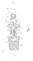
- Figure 1 is a cross-section side view of one embodiment of the invention.
- FIG 1 is cross-sectional side view of the invention shown in FIG 1 depicting only the bonnet, valve stem plunger, needle and endcap components of the valve.
- Figure 3 is an enlarged cross-sectional side view of that portion of the invention encircled in FIG 2.
- minor portion means less than 50%.
- fraction means less than 10%.
- Poiseuille's Law refers to the mathematical equation set forth below which was developed by the French physician Jean Poiseuille to describe the rate of flow of a fluid through a lumen based upon the diameter, length and pressure drop along the lumen.
- R ⁇ ⁇ r 4 ⁇ ⁇ P / 8 ⁇ ⁇ l
- the invention is a flow control valve 10 with a hollow needle 70 effective for directing some of the fluid pass through the valve 10 (hereinafter "source fluid") into the valve 10 itself. That portion of the source fluid flowing through the lumen 79 in the needle 70 displaces any environmental fluid present within the valve 10. By flushing any environmental fluid present in the valve 10 with source fluid, environmental fluid is prevented from leaking into the valve 10. This significantly reduces the possibility that source fluid exiting the valve 10 through the first orifice 27 or second orifice 28 will be contaminated with environmental fluid which is of particular concern when the source fluid is to be analyzed downstream from the valve 10 for the presence of a component found in the environmental fluid, such as analyzing a source gas for O 2 , or H 2 O content.
- a needle valve includes a valve body or bonnet 20, a knob 30, a bonnet nut 40. a valve stem screw 50, a valve stem plunger 60, a needle 70 and an endcap 80.
- the valve body 20 defines a chamber 29 sealingly divided by the valve stem plunger 60 into a first portion 29a and a second portion 29b.
- the valve body 20 and the endcap 80 provide a first orifice 27 and a second orifice 28 in fluid communication with the first portion 29a of the chamber 29 for permitting controlled flow of a source fluid through the first portion 29a of the chamber 29.
- the knob 30 is rotatably attached to a first end (unnumbered) of the valve body 20 by the bonnet nut 40.
- the valve stem screw 50 is positioned within the chamber 29 defined by the valve body 20 and attached at a first end (unnumbered) to the knob 30 for coterminous rotation of the valve stem screw 50 with rotation of the knob 30 about a longitudinal axis x.
- the valve stem plunger 60 is positioned within the chamber 29 defined by the valve body 20 and includes an O-ring seal (unnumbered) for sealingly engaging the inner wall (unnumbered) of the valve body 20 so as to divide the chamber 29 into the first portion 29a and the second portion 29b.
- the first end (unnumbered) of the valve stem plunger 60 includes an internally threaded bore 65 threadably engaging an externally threaded shaft 51 on the valve stem screw 50 for translating rotation of the valve stem screw 50 - effected by rotation of knob 30 - into longitudinal x movement of the valve stem plunger 60 within the chamber 29.
- An orifice 69 is provided through the valve stem plunger 60 for placing the internally threaded bore 65 defined by the valve stem plunger 60 into fluid communication with the void volume (not separately numbered) between the valve stem plunger 60 and the valve body 20.
- the needle 70 is fixedly attached to the second end (unnumbered) of the valve stem plunger 60 and extends longitudinally x from the valve stem plunger 60 into the first orifice 27, which is preferably the inlet or high pressure orifice, through endcap 80.
- the needle 70 is tapered so that the size of the opening through the first orifice 27 can be adjusted - and hence the flow of source fluid through the first orifice 27 - by longitudinal movement of the needle 70 relative to the first orifice 27. Since the needle 70 is fixedly attached to the second end (unnumbered) of the valve stem plunger 60, the needle 70 can be longitudinally x repositioned by rotation of the knob 30.
- a lumen 79 extends through the needle 70 with a first end 79a of the lumen 79 in fluid communication with the first portion 29a of the chamber 29 and a second end 79b of the lumen 79 in fluid communication with the second portion 29b of the chamber 29.
- the lumen 79 functions as a conduit through which a quantity of the source fluid flowing into the first portion 29a of the chamber 29 can flow into the second portion 29b of the chamber 29 ( i . e ., into internally threaded bore 65 defined by the valve stem plunger 60 and then through orifice 69 into the void volume between the valve stem plunger 60 and the valve body 20 ).
- the source fluid flowing into the second portion 29b of the chamber 29 will displace any environmental fluid within the second portion 29b of the chamber 29 and exit the second portion 29b of the chamber 29 through any available leaks, cracks, gaps and fissures in the valve 10.
- the diameter (unnumbered) of the lumen 79 through the needle 70 and the diameter of the orifice 69 through the valve stem plunger 60 can each be selected as necessary to provide the desired flow rate of source fluid through the second portion 29b of the chamber 29, with the quantity of source fluid flowing through orifice 69 and lumen 79 governed by Poiseuille's Law.
- a flow rate of between about 1 cm 3 per minute and 10 cm 3 per minute is desired as a flow rate of less than about 1 cm 3 per minute may be ineffective for completely displacing environmental fluid within the valve 10 while a flow rate of greater than about 10 cm 3 per minute siphons off excessive source fluid with only minimal concomitant advantage in the displacement of environmental fluid from the valve 10.
Landscapes
- Engineering & Computer Science (AREA)
- General Engineering & Computer Science (AREA)
- Mechanical Engineering (AREA)
- Lift Valve (AREA)
- Infusion, Injection, And Reservoir Apparatuses (AREA)
- Check Valves (AREA)
- Details Of Valves (AREA)
Applications Claiming Priority (1)
| Application Number | Priority Date | Filing Date | Title |
|---|---|---|---|
| US11/349,824 US7429027B2 (en) | 2006-02-08 | 2006-02-08 | Self-flushing needle valve |
Publications (3)
| Publication Number | Publication Date |
|---|---|
| EP1818583A2 true EP1818583A2 (de) | 2007-08-15 |
| EP1818583A3 EP1818583A3 (de) | 2012-10-10 |
| EP1818583B1 EP1818583B1 (de) | 2017-11-29 |
Family
ID=38009646
Family Applications (1)
| Application Number | Title | Priority Date | Filing Date |
|---|---|---|---|
| EP07101081.3A Not-in-force EP1818583B1 (de) | 2006-02-08 | 2007-01-24 | Selbstspülendes Nadelventil |
Country Status (2)
| Country | Link |
|---|---|
| US (1) | US7429027B2 (de) |
| EP (1) | EP1818583B1 (de) |
Families Citing this family (2)
| Publication number | Priority date | Publication date | Assignee | Title |
|---|---|---|---|---|
| FR2988403B1 (fr) * | 2012-03-20 | 2014-05-09 | Riber | Appareil de depot sous vide a cellules a vanne comportant un dispositif de detection de fuite et procede de detection d'une fuite dans un appareil de depot sous vide |
| US9080994B2 (en) * | 2012-10-11 | 2015-07-14 | Mocon, Inc. | Analyte sensor with spent gas flushed endcaps |
Family Cites Families (7)
| Publication number | Priority date | Publication date | Assignee | Title |
|---|---|---|---|---|
| US3318577A (en) * | 1965-05-24 | 1967-05-09 | George W Banks | High pressure valve having soft seating and balanced seal |
| US3976279A (en) * | 1973-11-05 | 1976-08-24 | High Pressure Equipment Co. Inc. | High pressure valve |
| US3933174A (en) * | 1974-05-20 | 1976-01-20 | Sanko Engineering & Construction Co., Ltd. | Valve with a pulsation damping device |
| US4341370A (en) * | 1980-11-20 | 1982-07-27 | Banks George W | High pressure, three stage, balanced valve |
| JPH061124Y2 (ja) * | 1988-09-28 | 1994-01-12 | オムロン株式会社 | 血圧計のエアコネクタ |
| US5386965A (en) * | 1993-06-04 | 1995-02-07 | Ber-Lo Manufacturing Company, Inc. | High pressure flow valve with pressure assist valve seal |
| US7000895B2 (en) * | 2002-11-01 | 2006-02-21 | Woodward Governor Company | Valve having pressure balancing piston and method involving same |
-
2006
- 2006-02-08 US US11/349,824 patent/US7429027B2/en not_active Expired - Lifetime
-
2007
- 2007-01-24 EP EP07101081.3A patent/EP1818583B1/de not_active Not-in-force
Also Published As
| Publication number | Publication date |
|---|---|
| EP1818583B1 (de) | 2017-11-29 |
| US7429027B2 (en) | 2008-09-30 |
| US20070181837A1 (en) | 2007-08-09 |
| EP1818583A3 (de) | 2012-10-10 |
Similar Documents
| Publication | Publication Date | Title |
|---|---|---|
| BRPI0911965B8 (pt) | aparelho e método para controlar fluxo de sangue através de um cateter intravenoso | |
| IL130807A0 (en) | Fluidic device for medical diagnostics | |
| MY133802A (en) | Capillary flow control in a medical diagnostic device | |
| ES2002269A6 (es) | Dispositivo de regulacion del caudal de paso | |
| CA2053719A1 (en) | Drilling apparatus, particularly wire line core drilling apparatus | |
| EP1605155A3 (de) | Ventil mit Kontaminationsgegenmassnahmen | |
| GB0519119D0 (en) | Apparatus and method | |
| EP1818583B1 (de) | Selbstspülendes Nadelventil | |
| DE2952480A1 (de) | Vorrichtung und verfahren zur aufnahme und lagerung fluessiger umsetzungsstoffe | |
| EP3688459B1 (de) | Vorrichtung zur erfassung der qualität einer flüssigkeit in einem versorgungsrohr | |
| EP1104882A2 (de) | Sondenvorrichtung zur Entnahme von flüchtigen Komponenten aus Flüssigkeiten oder Gasen | |
| DE4127938A1 (de) | Saugregler fuer eine pleurale drainagevorrichtung | |
| US5448922A (en) | Gas permeation system | |
| DE102010008527A1 (de) | Schnellschlussventil mit Dosierentlastung | |
| EP1762760A3 (de) | Rückschlagventil | |
| US4537219A (en) | Fluid-sampling valve for a hydraulic system | |
| US8118061B2 (en) | Variable flow rate controller | |
| DE10107648C1 (de) | Probenehmer | |
| SU823950A1 (ru) | Устройство дл отбора проб жидкости | |
| US20070101803A1 (en) | Apparatus for permeability analysis | |
| PT1864041E (pt) | Válvula para fluidos | |
| DE19604606A1 (de) | Meßvorrichtung für einen von wenigstens zwei flüchtigen Bestandteilen einer Flüssigkeit, insbesondere einer Fermentationsflüssigkeit | |
| RU2440495C1 (ru) | Приемная камера глубинного пробоотборника для отбора проб высоковязкой нефти и донного осадка | |
| EP2174125A1 (de) | Einspritzport für analysengeräte, anordnung zur betätigung eines einspritzports sowie analysengerät mit einem einspritzport | |
| DE2521473A1 (de) | Gasleckpruefvorrichtung |
Legal Events
| Date | Code | Title | Description |
|---|---|---|---|
| PUAI | Public reference made under article 153(3) epc to a published international application that has entered the european phase |
Free format text: ORIGINAL CODE: 0009012 |
|
| 17P | Request for examination filed |
Effective date: 20070223 |
|
| AK | Designated contracting states |
Kind code of ref document: A2 Designated state(s): AT BE BG CH CY CZ DE DK EE ES FI FR GB GR HU IE IS IT LI LT LU LV MC NL PL PT RO SE SI SK TR |
|
| AX | Request for extension of the european patent |
Extension state: AL BA HR MK YU |
|
| PUAL | Search report despatched |
Free format text: ORIGINAL CODE: 0009013 |
|
| AK | Designated contracting states |
Kind code of ref document: A3 Designated state(s): AT BE BG CH CY CZ DE DK EE ES FI FR GB GR HU IE IS IT LI LT LU LV MC NL PL PT RO SE SI SK TR |
|
| AX | Request for extension of the european patent |
Extension state: AL BA HR MK RS |
|
| RIC1 | Information provided on ipc code assigned before grant |
Ipc: F16K 1/38 20060101AFI20120904BHEP |
|
| AKX | Designation fees paid |
Designated state(s): AT BE BG CH CY CZ DE DK EE ES FI FR GB GR HU IE IS IT LI LT LU LV MC NL PL PT RO SE SI SK TR |
|
| 17Q | First examination report despatched |
Effective date: 20140714 |
|
| GRAP | Despatch of communication of intention to grant a patent |
Free format text: ORIGINAL CODE: EPIDOSNIGR1 |
|
| INTG | Intention to grant announced |
Effective date: 20170519 |
|
| INTG | Intention to grant announced |
Effective date: 20170522 |
|
| GRAS | Grant fee paid |
Free format text: ORIGINAL CODE: EPIDOSNIGR3 |
|
| GRAA | (expected) grant |
Free format text: ORIGINAL CODE: 0009210 |
|
| AK | Designated contracting states |
Kind code of ref document: B1 Designated state(s): AT BE BG CH CY CZ DE DK EE ES FI FR GB GR HU IE IS IT LI LT LU LV MC NL PL PT RO SE SI SK TR |
|
| RAP1 | Party data changed (applicant data changed or rights of an application transferred) |
Owner name: MOCON, INC. |
|
| REG | Reference to a national code |
Ref country code: GB Ref legal event code: FG4D |
|
| REG | Reference to a national code |
Ref country code: CH Ref legal event code: EP |
|
| REG | Reference to a national code |
Ref country code: AT Ref legal event code: REF Ref document number: 950694 Country of ref document: AT Kind code of ref document: T Effective date: 20171215 |
|
| REG | Reference to a national code |
Ref country code: IE Ref legal event code: FG4D |
|
| REG | Reference to a national code |
Ref country code: DE Ref legal event code: R096 Ref document number: 602007053192 Country of ref document: DE |
|
| REG | Reference to a national code |
Ref country code: FR Ref legal event code: PLFP Year of fee payment: 12 |
|
| REG | Reference to a national code |
Ref country code: NL Ref legal event code: MP Effective date: 20171129 |
|
| REG | Reference to a national code |
Ref country code: LT Ref legal event code: MG4D |
|
| REG | Reference to a national code |
Ref country code: AT Ref legal event code: MK05 Ref document number: 950694 Country of ref document: AT Kind code of ref document: T Effective date: 20171129 |
|
| PG25 | Lapsed in a contracting state [announced via postgrant information from national office to epo] |
Ref country code: LT Free format text: LAPSE BECAUSE OF FAILURE TO SUBMIT A TRANSLATION OF THE DESCRIPTION OR TO PAY THE FEE WITHIN THE PRESCRIBED TIME-LIMIT Effective date: 20171129 Ref country code: FI Free format text: LAPSE BECAUSE OF FAILURE TO SUBMIT A TRANSLATION OF THE DESCRIPTION OR TO PAY THE FEE WITHIN THE PRESCRIBED TIME-LIMIT Effective date: 20171129 Ref country code: SE Free format text: LAPSE BECAUSE OF FAILURE TO SUBMIT A TRANSLATION OF THE DESCRIPTION OR TO PAY THE FEE WITHIN THE PRESCRIBED TIME-LIMIT Effective date: 20171129 Ref country code: ES Free format text: LAPSE BECAUSE OF FAILURE TO SUBMIT A TRANSLATION OF THE DESCRIPTION OR TO PAY THE FEE WITHIN THE PRESCRIBED TIME-LIMIT Effective date: 20171129 |
|
| PG25 | Lapsed in a contracting state [announced via postgrant information from national office to epo] |
Ref country code: AT Free format text: LAPSE BECAUSE OF FAILURE TO SUBMIT A TRANSLATION OF THE DESCRIPTION OR TO PAY THE FEE WITHIN THE PRESCRIBED TIME-LIMIT Effective date: 20171129 Ref country code: BG Free format text: LAPSE BECAUSE OF FAILURE TO SUBMIT A TRANSLATION OF THE DESCRIPTION OR TO PAY THE FEE WITHIN THE PRESCRIBED TIME-LIMIT Effective date: 20180228 Ref country code: GR Free format text: LAPSE BECAUSE OF FAILURE TO SUBMIT A TRANSLATION OF THE DESCRIPTION OR TO PAY THE FEE WITHIN THE PRESCRIBED TIME-LIMIT Effective date: 20180301 Ref country code: LV Free format text: LAPSE BECAUSE OF FAILURE TO SUBMIT A TRANSLATION OF THE DESCRIPTION OR TO PAY THE FEE WITHIN THE PRESCRIBED TIME-LIMIT Effective date: 20171129 |
|
| PG25 | Lapsed in a contracting state [announced via postgrant information from national office to epo] |
Ref country code: NL Free format text: LAPSE BECAUSE OF FAILURE TO SUBMIT A TRANSLATION OF THE DESCRIPTION OR TO PAY THE FEE WITHIN THE PRESCRIBED TIME-LIMIT Effective date: 20171129 |
|
| PG25 | Lapsed in a contracting state [announced via postgrant information from national office to epo] |
Ref country code: DK Free format text: LAPSE BECAUSE OF FAILURE TO SUBMIT A TRANSLATION OF THE DESCRIPTION OR TO PAY THE FEE WITHIN THE PRESCRIBED TIME-LIMIT Effective date: 20171129 Ref country code: EE Free format text: LAPSE BECAUSE OF FAILURE TO SUBMIT A TRANSLATION OF THE DESCRIPTION OR TO PAY THE FEE WITHIN THE PRESCRIBED TIME-LIMIT Effective date: 20171129 Ref country code: CY Free format text: LAPSE BECAUSE OF FAILURE TO SUBMIT A TRANSLATION OF THE DESCRIPTION OR TO PAY THE FEE WITHIN THE PRESCRIBED TIME-LIMIT Effective date: 20171129 Ref country code: CZ Free format text: LAPSE BECAUSE OF FAILURE TO SUBMIT A TRANSLATION OF THE DESCRIPTION OR TO PAY THE FEE WITHIN THE PRESCRIBED TIME-LIMIT Effective date: 20171129 Ref country code: SK Free format text: LAPSE BECAUSE OF FAILURE TO SUBMIT A TRANSLATION OF THE DESCRIPTION OR TO PAY THE FEE WITHIN THE PRESCRIBED TIME-LIMIT Effective date: 20171129 |
|
| REG | Reference to a national code |
Ref country code: DE Ref legal event code: R097 Ref document number: 602007053192 Country of ref document: DE |
|
| PG25 | Lapsed in a contracting state [announced via postgrant information from national office to epo] |
Ref country code: PL Free format text: LAPSE BECAUSE OF FAILURE TO SUBMIT A TRANSLATION OF THE DESCRIPTION OR TO PAY THE FEE WITHIN THE PRESCRIBED TIME-LIMIT Effective date: 20171129 Ref country code: RO Free format text: LAPSE BECAUSE OF FAILURE TO SUBMIT A TRANSLATION OF THE DESCRIPTION OR TO PAY THE FEE WITHIN THE PRESCRIBED TIME-LIMIT Effective date: 20171129 Ref country code: IT Free format text: LAPSE BECAUSE OF FAILURE TO SUBMIT A TRANSLATION OF THE DESCRIPTION OR TO PAY THE FEE WITHIN THE PRESCRIBED TIME-LIMIT Effective date: 20171129 |
|
| REG | Reference to a national code |
Ref country code: CH Ref legal event code: PL |
|
| PLBE | No opposition filed within time limit |
Free format text: ORIGINAL CODE: 0009261 |
|
| STAA | Information on the status of an ep patent application or granted ep patent |
Free format text: STATUS: NO OPPOSITION FILED WITHIN TIME LIMIT |
|
| PG25 | Lapsed in a contracting state [announced via postgrant information from national office to epo] |
Ref country code: LU Free format text: LAPSE BECAUSE OF NON-PAYMENT OF DUE FEES Effective date: 20180124 |
|
| REG | Reference to a national code |
Ref country code: IE Ref legal event code: MM4A |
|
| 26N | No opposition filed |
Effective date: 20180830 |
|
| REG | Reference to a national code |
Ref country code: BE Ref legal event code: MM Effective date: 20180131 |
|
| PG25 | Lapsed in a contracting state [announced via postgrant information from national office to epo] |
Ref country code: LI Free format text: LAPSE BECAUSE OF NON-PAYMENT OF DUE FEES Effective date: 20180131 Ref country code: CH Free format text: LAPSE BECAUSE OF NON-PAYMENT OF DUE FEES Effective date: 20180131 Ref country code: BE Free format text: LAPSE BECAUSE OF NON-PAYMENT OF DUE FEES Effective date: 20180131 Ref country code: SI Free format text: LAPSE BECAUSE OF FAILURE TO SUBMIT A TRANSLATION OF THE DESCRIPTION OR TO PAY THE FEE WITHIN THE PRESCRIBED TIME-LIMIT Effective date: 20171129 |
|
| PG25 | Lapsed in a contracting state [announced via postgrant information from national office to epo] |
Ref country code: IE Free format text: LAPSE BECAUSE OF NON-PAYMENT OF DUE FEES Effective date: 20180124 |
|
| PG25 | Lapsed in a contracting state [announced via postgrant information from national office to epo] |
Ref country code: MC Free format text: LAPSE BECAUSE OF FAILURE TO SUBMIT A TRANSLATION OF THE DESCRIPTION OR TO PAY THE FEE WITHIN THE PRESCRIBED TIME-LIMIT Effective date: 20171129 |
|
| PG25 | Lapsed in a contracting state [announced via postgrant information from national office to epo] |
Ref country code: TR Free format text: LAPSE BECAUSE OF FAILURE TO SUBMIT A TRANSLATION OF THE DESCRIPTION OR TO PAY THE FEE WITHIN THE PRESCRIBED TIME-LIMIT Effective date: 20171129 |
|
| PG25 | Lapsed in a contracting state [announced via postgrant information from national office to epo] |
Ref country code: PT Free format text: LAPSE BECAUSE OF FAILURE TO SUBMIT A TRANSLATION OF THE DESCRIPTION OR TO PAY THE FEE WITHIN THE PRESCRIBED TIME-LIMIT Effective date: 20171129 Ref country code: HU Free format text: LAPSE BECAUSE OF FAILURE TO SUBMIT A TRANSLATION OF THE DESCRIPTION OR TO PAY THE FEE WITHIN THE PRESCRIBED TIME-LIMIT; INVALID AB INITIO Effective date: 20070124 |
|
| PG25 | Lapsed in a contracting state [announced via postgrant information from national office to epo] |
Ref country code: IS Free format text: LAPSE BECAUSE OF FAILURE TO SUBMIT A TRANSLATION OF THE DESCRIPTION OR TO PAY THE FEE WITHIN THE PRESCRIBED TIME-LIMIT Effective date: 20180329 |
|
| PGFP | Annual fee paid to national office [announced via postgrant information from national office to epo] |
Ref country code: GB Payment date: 20220131 Year of fee payment: 16 Ref country code: DE Payment date: 20220131 Year of fee payment: 16 |
|
| PGFP | Annual fee paid to national office [announced via postgrant information from national office to epo] |
Ref country code: FR Payment date: 20220110 Year of fee payment: 16 |
|
| REG | Reference to a national code |
Ref country code: DE Ref legal event code: R119 Ref document number: 602007053192 Country of ref document: DE |
|
| GBPC | Gb: european patent ceased through non-payment of renewal fee |
Effective date: 20230124 |
|
| PG25 | Lapsed in a contracting state [announced via postgrant information from national office to epo] |
Ref country code: GB Free format text: LAPSE BECAUSE OF NON-PAYMENT OF DUE FEES Effective date: 20230124 Ref country code: DE Free format text: LAPSE BECAUSE OF NON-PAYMENT OF DUE FEES Effective date: 20230801 |
|
| PG25 | Lapsed in a contracting state [announced via postgrant information from national office to epo] |
Ref country code: FR Free format text: LAPSE BECAUSE OF NON-PAYMENT OF DUE FEES Effective date: 20230131 |