EP1818561A1 - Shock absorbing compound material structure, process for producing the structure and traveling body or sailing body employing the structure - Google Patents
Shock absorbing compound material structure, process for producing the structure and traveling body or sailing body employing the structure Download PDFInfo
- Publication number
- EP1818561A1 EP1818561A1 EP04771145A EP04771145A EP1818561A1 EP 1818561 A1 EP1818561 A1 EP 1818561A1 EP 04771145 A EP04771145 A EP 04771145A EP 04771145 A EP04771145 A EP 04771145A EP 1818561 A1 EP1818561 A1 EP 1818561A1
- Authority
- EP
- European Patent Office
- Prior art keywords
- impact
- composite structure
- absorbing composite
- absorbing
- needling
- Prior art date
- Legal status (The legal status is an assumption and is not a legal conclusion. Google has not performed a legal analysis and makes no representation as to the accuracy of the status listed.)
- Granted
Links
Images






Classifications
-
- F—MECHANICAL ENGINEERING; LIGHTING; HEATING; WEAPONS; BLASTING
- F16—ENGINEERING ELEMENTS AND UNITS; GENERAL MEASURES FOR PRODUCING AND MAINTAINING EFFECTIVE FUNCTIONING OF MACHINES OR INSTALLATIONS; THERMAL INSULATION IN GENERAL
- F16F—SPRINGS; SHOCK-ABSORBERS; MEANS FOR DAMPING VIBRATION
- F16F7/00—Vibration-dampers; Shock-absorbers
- F16F7/12—Vibration-dampers; Shock-absorbers using plastic deformation of members
- F16F7/124—Vibration-dampers; Shock-absorbers using plastic deformation of members characterised by their special construction from fibre-reinforced plastics
-
- B—PERFORMING OPERATIONS; TRANSPORTING
- B32—LAYERED PRODUCTS
- B32B—LAYERED PRODUCTS, i.e. PRODUCTS BUILT-UP OF STRATA OF FLAT OR NON-FLAT, e.g. CELLULAR OR HONEYCOMB, FORM
- B32B5/00—Layered products characterised by the non- homogeneity or physical structure, i.e. comprising a fibrous, filamentary, particulate or foam layer; Layered products characterised by having a layer differing constitutionally or physically in different parts
- B32B5/02—Layered products characterised by the non- homogeneity or physical structure, i.e. comprising a fibrous, filamentary, particulate or foam layer; Layered products characterised by having a layer differing constitutionally or physically in different parts characterised by structural features of a fibrous or filamentary layer
- B32B5/06—Layered products characterised by the non- homogeneity or physical structure, i.e. comprising a fibrous, filamentary, particulate or foam layer; Layered products characterised by having a layer differing constitutionally or physically in different parts characterised by structural features of a fibrous or filamentary layer characterised by a fibrous or filamentary layer mechanically connected, e.g. by needling to another layer, e.g. of fibres, of paper
-
- B—PERFORMING OPERATIONS; TRANSPORTING
- B32—LAYERED PRODUCTS
- B32B—LAYERED PRODUCTS, i.e. PRODUCTS BUILT-UP OF STRATA OF FLAT OR NON-FLAT, e.g. CELLULAR OR HONEYCOMB, FORM
- B32B5/00—Layered products characterised by the non- homogeneity or physical structure, i.e. comprising a fibrous, filamentary, particulate or foam layer; Layered products characterised by having a layer differing constitutionally or physically in different parts
- B32B5/22—Layered products characterised by the non- homogeneity or physical structure, i.e. comprising a fibrous, filamentary, particulate or foam layer; Layered products characterised by having a layer differing constitutionally or physically in different parts characterised by the presence of two or more layers which are next to each other and are fibrous, filamentary, formed of particles or foamed
- B32B5/24—Layered products characterised by the non- homogeneity or physical structure, i.e. comprising a fibrous, filamentary, particulate or foam layer; Layered products characterised by having a layer differing constitutionally or physically in different parts characterised by the presence of two or more layers which are next to each other and are fibrous, filamentary, formed of particles or foamed one layer being a fibrous or filamentary layer
- B32B5/26—Layered products characterised by the non- homogeneity or physical structure, i.e. comprising a fibrous, filamentary, particulate or foam layer; Layered products characterised by having a layer differing constitutionally or physically in different parts characterised by the presence of two or more layers which are next to each other and are fibrous, filamentary, formed of particles or foamed one layer being a fibrous or filamentary layer another layer next to it also being fibrous or filamentary
-
- B—PERFORMING OPERATIONS; TRANSPORTING
- B32—LAYERED PRODUCTS
- B32B—LAYERED PRODUCTS, i.e. PRODUCTS BUILT-UP OF STRATA OF FLAT OR NON-FLAT, e.g. CELLULAR OR HONEYCOMB, FORM
- B32B5/00—Layered products characterised by the non- homogeneity or physical structure, i.e. comprising a fibrous, filamentary, particulate or foam layer; Layered products characterised by having a layer differing constitutionally or physically in different parts
- B32B5/22—Layered products characterised by the non- homogeneity or physical structure, i.e. comprising a fibrous, filamentary, particulate or foam layer; Layered products characterised by having a layer differing constitutionally or physically in different parts characterised by the presence of two or more layers which are next to each other and are fibrous, filamentary, formed of particles or foamed
- B32B5/24—Layered products characterised by the non- homogeneity or physical structure, i.e. comprising a fibrous, filamentary, particulate or foam layer; Layered products characterised by having a layer differing constitutionally or physically in different parts characterised by the presence of two or more layers which are next to each other and are fibrous, filamentary, formed of particles or foamed one layer being a fibrous or filamentary layer
- B32B5/28—Layered products characterised by the non- homogeneity or physical structure, i.e. comprising a fibrous, filamentary, particulate or foam layer; Layered products characterised by having a layer differing constitutionally or physically in different parts characterised by the presence of two or more layers which are next to each other and are fibrous, filamentary, formed of particles or foamed one layer being a fibrous or filamentary layer impregnated with or embedded in a plastic substance
-
- B—PERFORMING OPERATIONS; TRANSPORTING
- B32—LAYERED PRODUCTS
- B32B—LAYERED PRODUCTS, i.e. PRODUCTS BUILT-UP OF STRATA OF FLAT OR NON-FLAT, e.g. CELLULAR OR HONEYCOMB, FORM
- B32B2260/00—Layered product comprising an impregnated, embedded, or bonded layer wherein the layer comprises an impregnation, embedding, or binder material
- B32B2260/02—Composition of the impregnated, bonded or embedded layer
- B32B2260/021—Fibrous or filamentary layer
-
- B—PERFORMING OPERATIONS; TRANSPORTING
- B32—LAYERED PRODUCTS
- B32B—LAYERED PRODUCTS, i.e. PRODUCTS BUILT-UP OF STRATA OF FLAT OR NON-FLAT, e.g. CELLULAR OR HONEYCOMB, FORM
- B32B2260/00—Layered product comprising an impregnated, embedded, or bonded layer wherein the layer comprises an impregnation, embedding, or binder material
- B32B2260/02—Composition of the impregnated, bonded or embedded layer
- B32B2260/021—Fibrous or filamentary layer
- B32B2260/023—Two or more layers
-
- B—PERFORMING OPERATIONS; TRANSPORTING
- B32—LAYERED PRODUCTS
- B32B—LAYERED PRODUCTS, i.e. PRODUCTS BUILT-UP OF STRATA OF FLAT OR NON-FLAT, e.g. CELLULAR OR HONEYCOMB, FORM
- B32B2260/00—Layered product comprising an impregnated, embedded, or bonded layer wherein the layer comprises an impregnation, embedding, or binder material
- B32B2260/04—Impregnation, embedding, or binder material
- B32B2260/046—Synthetic resin
-
- B—PERFORMING OPERATIONS; TRANSPORTING
- B32—LAYERED PRODUCTS
- B32B—LAYERED PRODUCTS, i.e. PRODUCTS BUILT-UP OF STRATA OF FLAT OR NON-FLAT, e.g. CELLULAR OR HONEYCOMB, FORM
- B32B2307/00—Properties of the layers or laminate
- B32B2307/50—Properties of the layers or laminate having particular mechanical properties
- B32B2307/558—Impact strength, toughness
-
- B—PERFORMING OPERATIONS; TRANSPORTING
- B32—LAYERED PRODUCTS
- B32B—LAYERED PRODUCTS, i.e. PRODUCTS BUILT-UP OF STRATA OF FLAT OR NON-FLAT, e.g. CELLULAR OR HONEYCOMB, FORM
- B32B2307/00—Properties of the layers or laminate
- B32B2307/50—Properties of the layers or laminate having particular mechanical properties
- B32B2307/56—Damping, energy absorption
-
- B—PERFORMING OPERATIONS; TRANSPORTING
- B32—LAYERED PRODUCTS
- B32B—LAYERED PRODUCTS, i.e. PRODUCTS BUILT-UP OF STRATA OF FLAT OR NON-FLAT, e.g. CELLULAR OR HONEYCOMB, FORM
- B32B2605/00—Vehicles
- B32B2605/003—Interior finishings
-
- B—PERFORMING OPERATIONS; TRANSPORTING
- B32—LAYERED PRODUCTS
- B32B—LAYERED PRODUCTS, i.e. PRODUCTS BUILT-UP OF STRATA OF FLAT OR NON-FLAT, e.g. CELLULAR OR HONEYCOMB, FORM
- B32B2605/00—Vehicles
- B32B2605/18—Aircraft
-
- Y—GENERAL TAGGING OF NEW TECHNOLOGICAL DEVELOPMENTS; GENERAL TAGGING OF CROSS-SECTIONAL TECHNOLOGIES SPANNING OVER SEVERAL SECTIONS OF THE IPC; TECHNICAL SUBJECTS COVERED BY FORMER USPC CROSS-REFERENCE ART COLLECTIONS [XRACs] AND DIGESTS
- Y10—TECHNICAL SUBJECTS COVERED BY FORMER USPC
- Y10T—TECHNICAL SUBJECTS COVERED BY FORMER US CLASSIFICATION
- Y10T428/00—Stock material or miscellaneous articles
- Y10T428/249921—Web or sheet containing structurally defined element or component
-
- Y—GENERAL TAGGING OF NEW TECHNOLOGICAL DEVELOPMENTS; GENERAL TAGGING OF CROSS-SECTIONAL TECHNOLOGIES SPANNING OVER SEVERAL SECTIONS OF THE IPC; TECHNICAL SUBJECTS COVERED BY FORMER USPC CROSS-REFERENCE ART COLLECTIONS [XRACs] AND DIGESTS
- Y10—TECHNICAL SUBJECTS COVERED BY FORMER USPC
- Y10T—TECHNICAL SUBJECTS COVERED BY FORMER US CLASSIFICATION
- Y10T428/00—Stock material or miscellaneous articles
- Y10T428/249921—Web or sheet containing structurally defined element or component
- Y10T428/249924—Noninterengaged fiber-containing paper-free web or sheet which is not of specified porosity
- Y10T428/24994—Fiber embedded in or on the surface of a polymeric matrix
- Y10T428/249941—Fiber is on the surface of a polymeric matrix having no embedded portion
-
- Y—GENERAL TAGGING OF NEW TECHNOLOGICAL DEVELOPMENTS; GENERAL TAGGING OF CROSS-SECTIONAL TECHNOLOGIES SPANNING OVER SEVERAL SECTIONS OF THE IPC; TECHNICAL SUBJECTS COVERED BY FORMER USPC CROSS-REFERENCE ART COLLECTIONS [XRACs] AND DIGESTS
- Y10—TECHNICAL SUBJECTS COVERED BY FORMER USPC
- Y10T—TECHNICAL SUBJECTS COVERED BY FORMER US CLASSIFICATION
- Y10T428/00—Stock material or miscellaneous articles
- Y10T428/31504—Composite [nonstructural laminate]
-
- Y—GENERAL TAGGING OF NEW TECHNOLOGICAL DEVELOPMENTS; GENERAL TAGGING OF CROSS-SECTIONAL TECHNOLOGIES SPANNING OVER SEVERAL SECTIONS OF THE IPC; TECHNICAL SUBJECTS COVERED BY FORMER USPC CROSS-REFERENCE ART COLLECTIONS [XRACs] AND DIGESTS
- Y10—TECHNICAL SUBJECTS COVERED BY FORMER USPC
- Y10T—TECHNICAL SUBJECTS COVERED BY FORMER US CLASSIFICATION
- Y10T442/00—Fabric [woven, knitted, or nonwoven textile or cloth, etc.]
- Y10T442/20—Coated or impregnated woven, knit, or nonwoven fabric which is not [a] associated with another preformed layer or fiber layer or, [b] with respect to woven and knit, characterized, respectively, by a particular or differential weave or knit, wherein the coating or impregnation is neither a foamed material nor a free metal or alloy layer
- Y10T442/2615—Coating or impregnation is resistant to penetration by solid implements
- Y10T442/2623—Ballistic resistant
Definitions
- the present invention relates to an impact-absorbing composite structure including a resin and a fiber laminated body that absorbs an impact by self destruction when an impact is applied, a method of manufacturing the impact-absorbing composite structure, and a driving object or an aviating object that employs the impact-absorbing composite structure.
- An energy absorbing member that absorbs impact energy is used around a seat of an airplane, around a seat of a vehicle, around a bumper, and in each structural member (see, for example, Japanese Patent Application Laid-open Publication No. S60-109630 and Japanese Patent Application Laid-open Publication No. S62-17438 ). Since it necessitates that the energy absorbing member is light and has high rigidity apart from having a capability to absorb the impact energy, a composite material of a resin and a reinforced fiber, so called fiber reinforced plastic (FRP), especially carbon fiber reinforced plastic (CFRP) is suitable.
- FRP fiber reinforced plastic
- CFRP carbon fiber reinforced plastic
- an impact resistance in a vehicle mainly a frontal impact accident is apprehended, and as a measure against this, a member called as a front side member made of steel is disposed in a hood, and energy is absorbed by crushing of the member upon the frontal impact accident.
- the strength between the layers and of the composition plane is improved and a contribution is made to improve a bending strength, however when it has received a compression such as it is received by the energy absorbing member, it is not the one that controls to absorb the impact while destroying a resin, and since this has a high strength as a medium even if it is used just as an energy absorbing member, it is not something that can absorb the impact effectively.
- An impact-absorbing composite structure is formed with a resin and a fiber laminated body, and absorbs, when experiencing an impact, the impact by self destruction.
- An interlayer-strength improvement technique is applied on the impact-absorbing composite structure in an oblique manner or in a gradual manner.
- the interlayer-strength improvement technique is any one of a needling, a stitching, and a three-dimensional fabric.
- a destruction due to an impact progresses when there is an initial load, and then the impact is sustained from a middle of delamination of the laminated body to prevent an impact absorbing ability of the impact-absorbing composite structure from being deteriorated.
- a method according to another aspect of the present invention which is for manufacturing an impact-absorbing composite structure that is formed with a fiber laminated body, and absorbs, when experiencing an impact, the impact by self destruction, includes impregnating a resin in the fiber laminated body; and applying an interlayer-strength improvement technique on the impact-absorbing composite structure.
- a method according to still another aspect of the present invention which is for manufacturing an impact-absorbing composite structure that is formed with a fiber laminated body, and absorbs, when experiencing an impact, the impact by self destruction, includes applying interlayer-strength improvement technique on the fiber laminated body; and impregnating a resin in the fiber laminated body.
- a driving object according to still another aspect of the present invention includes the impact-absorbing composite structure according to the present invention.
- An aviating object according to still another aspect of the present invention includes the impact-absorbing composite structure according to the present invention.
- an interlayer reinforcing area is provided by using a needling in the abovementioned impact-absorbing composite structure as an interlayer-strength improvement technique, it is possible to improve an amount of energy absorbed, and when an impact is applied, it is possible to perform a fixed-time control of a progress of destruction while absorbing the impact by self destruction.
- An impact-absorbing composite structure is an impact-absorbing composite structure formed by a resin and a fiber laminated body that absorbs an impact by self destruction when the impact is applied, and is a structure that is formed by providing an interlayer-strength improvement technique in an oblique manner or in a gradual manner, to the abovementioned impact-absorbing composite structure.
- the interlayer-strength improvement technique is applied in an oblique manner or in a gradual manner, and the interlayer strength is improved by holding out the impact from a time during the destruction.
- a needling, a stitching, and a three-dimensional fabric can be named as interlayer-strength improvement techniques for example.
- the "oblique manner” means to cause to change a frequency of the interlayer-strength improvement technique together with a distance, and includes as well to cause to change continuously.
- the “gradual manner” means to cause to change the frequency of the interlayer-strength improvement technique for each fixed distance, and includes as well a case of causing to change in a gradual manner and a case of causing to change discontinuously.
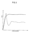
- FIG. 3 is a diagram of a relation between an impact load and a displacement.
- a cylindrical shaped impact-absorbing composite structure 11 is used.
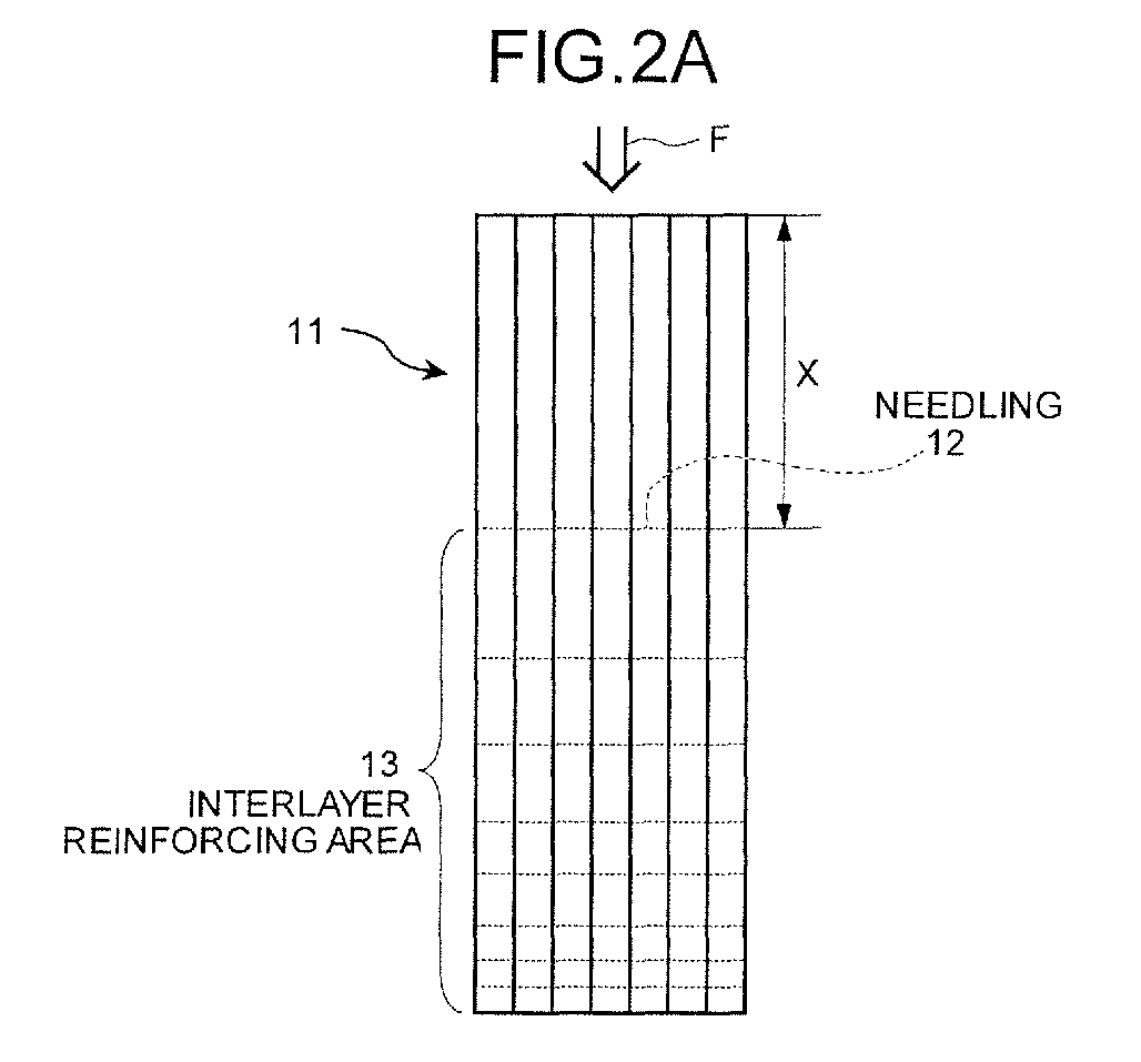
- Figs. 2A and 2B are A-A cross sections of Fig. 1, and as the interlayer-strength improvement technique, an interlayer reinforcing area 13 is provided by using a needling 12 to the abovementioned impact-absorbing composite structure, and the strength is reinforced so that the progress of a destruction is not advanced at once.
- the interlayer reinforcing area 13 is formed by the needling 12 such that the distance is reduced gradually from an upper end towards a lower end in the diagram, that is a load axial of an impact load F
- the present invention is not restricted to this and the needling may be applied with a fixed distance, and furthermore by widening and shortening the distance appropriately, the target impact absorbing efficiency is improved.
- the interlayer-strength improvement technique is not applied from the end portion of the impact-absorbing composite structure 11 up to a predetermined position X.
- the amount of energy absorbed became 90 kJ/kg and as compared to the amount of energy absorbed 60 kJ/kg when the interlayer reinforcing area is not provided, the amount of energy absorbed increased by 50%.
- the impact-absorbing composite structure according to the present invention has the amount of energy absorbed that is greater than or equal to that of these impact absorbing materials.
- Fig. 4 is a result when a frequency is changed with the needling applied and compared with a case where needling is not applied.
- a fiber orientation (+45/0/-45/0/0/-45/0/+45) laminated body prepreg was used as a test specimen and a static compression test was performed.
- a specimen that has a cylindrical shape similar to that in Fig. 1, a diameter 50 mm, and a height 75 mm was used.
- the needling was performed with a constant pitch from a position 5 mm from an upper end of a cylinder up to a lower end.
- the needling was performed with frequencies 0 times/cm2, 27 times/cm2, and 50 times/cm2. The result is shown in Fig. 4.
- Fig. 5A is a diagram in which the needling is not applied up to the predetermined position X, and then as shown in Figs. 2A and 2B a distance of the needling is changed gradually from wide to close (the needling pitched is shortened gradually).
- Fig. 5B is a diagram in which the needling is not applied up to the predetermined position X, and then the needling is applied with a constant distance.
- Fig. 5C is a diagram in which the needling is not applied up to the predetermined position X, and then the needling is applied after the needling distance is let to be close, from midway changed to wide, and then again close.
- Fig. 5A is a diagram in which the needling is not applied up to the predetermined position X, and then as shown in Figs. 2A and 2B a distance of the needling is changed gradually from wide to close (the needling pitched is shortened gradually).
- Fig. 5B is a diagram in which the needling is not applied up to the predetermined position
- FIG. 5D is a diagram in which the needling is not applied up to the predetermined position X, and then the needling is applied after the needling distance is let to be close, from midway changed to wide, and then kept constant.
- Fig. 5E is a diagram in which the needling is not applied up to the predetermined position X, and then the needling distance is let to be close from wide, and then let to be wide from close. Further, the needling is not applied on an end portion and a destruction-start portion is provided.
- Fig. 5F is a diagram in which the needling is not applied up to the predetermined position X, and then the needling distance is let to be close with a constant distance. Further, the needling is not applied on the end portion and the destruction-start portion is provided.
- FIG. 5G is a diagram in which the needling is not applied up to the predetermined position X, and then the needling distance is repeatedly changed from wide to close alternately, and in the end let to be close. Further, the needling is not applied on the end portion and the destruction-start portion is provided.
- Fig. 5H is a diagram in which the needling is not applied up to the predetermined position X, and then gradually the needling distance is changed from close to wide, and then again gradually changed to close. Further, the needling is not applied on the end portion and the destruction-start portion is provided.
- the pattern in which a needling reinforced area is formed in an oblique manner or in a gradual manner is not restricted to the one described above.
- the needling distance of the abovementioned pattern is regulated, apart from this the frequency of needling may be changed according to a location.
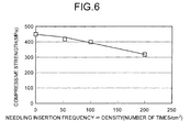
- Fig. 6 is a diagram of a relation between a needling insertion frequency and a compressive strength. As it is evident from Fig. 6, when the needling frequency is increased to greater than or equal to 75 times/cm 2, since a drop in the compressive strength was observed, if the needling is performed beyond the required frequency, there is a decline in the strength.
- a fiber material of the fiber laminated body that forms the impact-absorbing composite structure is not restricted to any particular material, and a carbon fiber, a glass fiber, a ceramic fiber, an aramid fiber (KEVLAR (registered trademark) etc.), an aromatic polyamide fiber, alumina fiber, and a silicon carbide fiber or a boron fiber are examples.
- thermosetting resins such as an epoxy resin, an unsaturated polyester resin, a phenol resin, an epoxy acrylate (vinylester) resin, a bismaleimide resin, a polyimide resin, a guanamine resin, a furan resin, a polyurethane resin, a polydiarylphthalate resin, and an amino resin are examples.
- polyamides such as nylon 6, nylon 66, nylon 11, nylon 610, and nylon 612, and their copolyamides, polyesters such as polyethylene terephthalate and polybutylene terephthalate, or their copolyesters, moreover, thermoplastic elastomers typified by polyester elastomers and polyamide elastomers, and furthermore polycarbonates, polyamide imides, polyphenylenesulfides, polyphenyleneoxides, polysulfones, polyethersulfones, polyetherether ketones, polyetherimides, and polyolefins are the examples.
- rubbers such as acrylic rubber, acrylonitrile butadiene rubber, urethane rubber, silicone rubber, styrene butadiene rubber, and fluoro rubber can be used as a resin that satisfy the range described above, and moreover, combined resins that are constituted by combining a plurality of resins selected from the rubbers, the thermoplastic resins, and the thermosetting resins mentioned above may as well be used.
- the impact-absorbing composite structure is not restricted to the cylindrical shaped as shown in Fig. 1, and apart from a cylinder with its apex having a conical shape or spherical shaped, an angular cylinder, a cone, an pyramid, a truncated cone, a truncated pyramid, or a cylinder having an oval shaped transverse section, furthermore a cylindrical shape such as a cylinder (or an angular cylinder) provided with a flange portion may be used. Moreover, apart from the cylindrical shape, it may be let to be a pilaster shaped such as a circular cylinder and an angular cylinder. Moreover, it may be formed by one member but not restricted to this and may be formed by piling up or combining a plurality of members.
- an initiator that becomes a starting point for the destruction to occur may be provided on one end or both ends of an impact load axial of the impact-absorbing composite structure.
- a manufacturing method of the impact-absorbing composite structure includes a cutting process (S11) of cutting the prepreg that includes a resin and a fiber laminated body to a predetermined length, then a lamination process (S12) of laminating these, a needling process (S13) of applying needling as the interlayer strength improvement technique on the laminated body, a jig mounting process (S14) of mounting the laminated body on which the needling is applied on a jig, a hardening process by pressurizing and heating (S15) of hardening by heating while pressurizing after mounting on the jig, and a cutting and processing process of removing from the jig, cutting, and processing.
- This enables to obtain the impact-absorbing composite structure with the improved impact resistance.
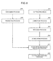
- Fig. 8 is an example in which it is formed by a vacuum resin impregnation forming method.
- the manufacturing method of the impact resisting composite structure includes the cutting process (S21) of cutting the fiber laminated body to a predetermined length, the lamination process (S22) of laminating these, the needling process (S23) of applying needling as the interlayer strength improvement technique on the laminated body, the jig mounting process (S24) of mounting the laminated body on which the needling is applied on the jig, a defoaming process (S25) of defoaming with the resin, a preheating process (S26) of preheating the resin that is defoamed, a hardening process by resin impregnation and heating of supplying the resin that is preheated in the preheating process (S26), impregnating it, and heat hardening, and the cutting and processing process (S28) of removing from the jig, cutting, and processing.
- Fig. 9 is a schematic diagram of a helicopter and shows a passenger 22 sitting on a seat 23 in a helicopter 21.
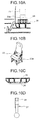
- Fig. 10A is an enlarged portion of a portion a in Fig. 9, in which the impact-absorbing composite structure is used in a mounting platform 24 of the seat 23 of the passenger 22.
- the mounting member that includes the impact-absorbing composite structure 11 between a floor face 25 and a seat leg 23a.
- Fig. 10B is an enlarged perspective view of the portion a in Fig. 9, in which the impact-absorbing composite structure is used as the impact resistant member in the seat leg 23a of the passenger 22.
- Fig. 10C is an enlarged portion of a portion b in Fig. 9, in which the impact-absorbing composite structure is used as the impact resistant member in an impact resisting structure portion 26 that is projected from an under floor of the helicopter 21.
- Fig. 10D is an enlarged portion of a portion c in Fig. 9, in which the impact-absorbing composite structure is used as the impact resistant member in a shock strut interior 28 of a wheel landing gear 27.
- the impact-absorbing composite structure according to the present invention can be used around a seat and for each structural member of a flight vehicle as the energy absorbing member that absorbs the impact energy efficiently. Moreover, it can be used not only in the flight vehicle but also around a seat and a bumper of a vehicle as the impact resistant member.
- the impact-absorbing composite structure according to the present invention can be used as an energy absorbing member that absorbs an impact energy efficiently, and in particular it is appropriate for use as an impact absorbing member around a seat and for each structural member of a flight vehicle such as a helicopter, and around a seat and a bumper of a vehicle such as a car.
Landscapes
- Engineering & Computer Science (AREA)
- General Engineering & Computer Science (AREA)
- Mechanical Engineering (AREA)
- Vibration Dampers (AREA)
- Laminated Bodies (AREA)
- Reinforced Plastic Materials (AREA)
Abstract
Description
- The present invention relates to an impact-absorbing composite structure including a resin and a fiber laminated body that absorbs an impact by self destruction when an impact is applied, a method of manufacturing the impact-absorbing composite structure, and a driving object or an aviating object that employs the impact-absorbing composite structure.
- An energy absorbing member that absorbs impact energy is used around a seat of an airplane, around a seat of a vehicle, around a bumper, and in each structural member (see, for example,
Japanese Patent Application Laid-open Publication No. S60-109630 Japanese Patent Application Laid-open Publication No. S62-17438 - Moreover, regarding an impact resistance in a vehicle, mainly a frontal impact accident is apprehended, and as a measure against this, a member called as a front side member made of steel is disposed in a hood, and energy is absorbed by crushing of the member upon the frontal impact accident.
- On the other hand, in a helicopter, an impact due to a forced landing is apprehended, and as a measure against it the impact resistant material is disposed under a floor. However, as compared to a length of the hood of the vehicle, in a structure under the floor of the helicopter, the height is limited for ensuring clearance under the floor. Furthermore, in recent years, since a need for a fuel tank under the floor becomes high for ensuring a cabin capacity, a restriction of an area and a stroke for disposing the impact resistant member is strict. Therefore, energy absorption efficiency higher than ever before is desired.
- For this reason, so far, as an energy absorbing member, in a laminated composite material in which fibers are laminated, upon evaluating an effect due to a fiber material or a fiber orientation, for suppressing a peak of an initial load, providing an initiator that becomes a starting point for the destruction to occur has been proposed (see, for example,
Japanese Patent Application Laid-open Publication No. H6-300068 Japanese Patent Application Laid-open Publication No. H6-341477 Japanese Patent Application Laid-open Publication No. H7-217689 Japanese Patent Application Laid-open Publication No. 2003-39429 - However, in the energy absorbing member disclosed in
Japanese Patent Application Laid-open Publication No. H6-300068 Japanese Patent Application Laid-open publication No. H6-341477 Japanese Patent Application Laid-open Publication No. H7-217689 Japanese Patent Application Laid-open Publication No. H6-300068 Japanese Patent Application Laid-open Publication No. H6-341477 - Moreover, in the textile substrate for the composite material disclosed in
Japanese Patent Application Laid-open Publication No. 2003-39429 - In view of the problems mentioned above, it is an object of the present invention to provide an impact-absorbing composite structure that can control the progress of the destruction while absorbing the impact by self destruction when the impact is applied, its manufacturing method, and a traveling body or a navigating body that uses it.
- An impact-absorbing composite structure according to one aspect of the present invention is formed with a resin and a fiber laminated body, and absorbs, when experiencing an impact, the impact by self destruction. An interlayer-strength improvement technique is applied on the impact-absorbing composite structure in an oblique manner or in a gradual manner.
- In the impact-absorbing composite structure according to the above aspect of the present invention, the interlayer-strength improvement technique is any one of a needling, a stitching, and a three-dimensional fabric.
- In the impact-absorbing composite structure according to the above aspect of the present invention, a destruction due to an impact progresses when there is an initial load, and then the impact is sustained from a middle of delamination of the laminated body to prevent an impact absorbing ability of the impact-absorbing composite structure from being deteriorated.
- A method according to another aspect of the present invention, which is for manufacturing an impact-absorbing composite structure that is formed with a fiber laminated body, and absorbs, when experiencing an impact, the impact by self destruction, includes impregnating a resin in the fiber laminated body; and applying an interlayer-strength improvement technique on the impact-absorbing composite structure.
- A method according to still another aspect of the present invention, which is for manufacturing an impact-absorbing composite structure that is formed with a fiber laminated body, and absorbs, when experiencing an impact, the impact by self destruction, includes applying interlayer-strength improvement technique on the fiber laminated body; and impregnating a resin in the fiber laminated body.
- A driving object according to still another aspect of the present invention includes the impact-absorbing composite structure according to the present invention.
- An aviating object according to still another aspect of the present invention includes the impact-absorbing composite structure according to the present invention.
- According to an impact-absorbing composite structure according to the present invention, since an interlayer reinforcing area is provided by using a needling in the abovementioned impact-absorbing composite structure as an interlayer-strength improvement technique, it is possible to improve an amount of energy absorbed, and when an impact is applied, it is possible to perform a fixed-time control of a progress of destruction while absorbing the impact by self destruction.
-
- Fig. 1 is a perspective view of an impact-absorbing composite structure according to the present embodiment;
- Figs. 2A and 2B are A-A cross sections of Fig. 1;
- Fig. 3 is a diagram of a relation between an impact load and a displacement according to the impact-absorbing composite structure;
- Fig. 4 is a diagram of a relation between a load and a collapse distance according to the impact-absorbing composite structure;
- Figs. 5A to 5H are diagrams that indicate an example of a pattern of a method for improving an interlayer strength;
- Fig. 6 is a diagram indicating a relation between a needling insertion frequency and a compressive strength;
- Fig. 7 is a manufacturing-process diagram of the impact-absorbing composite structure;
- Fig. 8 is another manufacturing-process diagram of the impact-absorbing composite structure;
- Fig. 9 is a schematic diagram of a helicopter in which the impact-absorbing composite structure is used; and
- Figs. 10A to 10D are enlarged views of main parts of Fig. 9.
-
- 11
- impact-absorbing composite structure
- 12
- needling
- 13
- interlayer reinforcing area
- Exemplary embodiments of the present invention are explained in detail below with reference to the accompanying drawings. However, the present invention is not limited to these embodiments.
- An impact-absorbing composite structure according to the present embodiment is an impact-absorbing composite structure formed by a resin and a fiber laminated body that absorbs an impact by self destruction when the impact is applied, and is a structure that is formed by providing an interlayer-strength improvement technique in an oblique manner or in a gradual manner, to the abovementioned impact-absorbing composite structure.
- According to the present invention, in this interlayer structure, the interlayer-strength improvement technique is applied in an oblique manner or in a gradual manner, and the interlayer strength is improved by holding out the impact from a time during the destruction.
- Here, a needling, a stitching, and a three-dimensional fabric can be named as interlayer-strength improvement techniques for example.
- Moreover, in "to apply the interlayer-strength improvement technique in an oblique manner", the "oblique manner " means to cause to change a frequency of the interlayer-strength improvement technique together with a distance, and includes as well to cause to change continuously. Furthermore, in "to apply the interlayer-strength improvement technique in a gradual manner", the "gradual manner" means to cause to change the frequency of the interlayer-strength improvement technique for each fixed distance, and includes as well a case of causing to change in a gradual manner and a case of causing to change discontinuously. Further, concretely, by referring to Figs. 5A to 5H an example of a pattern of its application is described later.
- Further, it is better not to apply the interlayer-strength improvement technique from an initiator portion and an end portion of the impact-absorbing composite structure due to a need to absorb the impact at an initial start of the self destruction, up to a predetermined position.
- A formation of the impact-absorbing composite structure in which the interlayer-strength improvement technique is applied is described below with reference to Fig. 1 and Figs. 2A and 2B. Fig. 3 is a diagram of a relation between an impact load and a displacement. As shown in Fig. 1, as an example, a cylindrical shaped impact-absorbing
composite structure 11 is used. Figs. 2A and 2B are A-A cross sections of Fig. 1, and as the interlayer-strength improvement technique, aninterlayer reinforcing area 13 is provided by using a needling 12 to the abovementioned impact-absorbing composite structure, and the strength is reinforced so that the progress of a destruction is not advanced at once. - Here, according to the present embodiment, although the
interlayer reinforcing area 13 is formed by the needling 12 such that the distance is reduced gradually from an upper end towards a lower end in the diagram, that is a load axial of an impact load F, the present invention is not restricted to this and the needling may be applied with a fixed distance, and furthermore by widening and shortening the distance appropriately, the target impact absorbing efficiency is improved. - According to the present invention, to absorb the impact effectively at the initial start of the self destruction, the interlayer-strength improvement technique is not applied from the end portion of the impact-absorbing
composite structure 11 up to a predetermined position X. - Further, as shown in Fig. 3, in a case where the
interlayer reinforcing area 13 is provided as according to the present embodiment, as shown by a solid line, even after an initial load is exerted, it is possible to hold the impact load during the fixed period of time, and the destruction is progressed at a fixed load. As a result, an amount of energy absorbed increases. Whereas, in a case where the interlayer reinforcing area such as the needling is not provided, as shown by a dashed line, a large load is exerted at a time of start of destruction, the destruction progressed at once, the energy absorption suddenly became small, and the impact could not be maintained from during the destruction. - As a result, when the interlayer reinforcing area is provided, the amount of energy absorbed became 90 kJ/kg and as compared to the amount of energy absorbed 60 kJ/kg when the interlayer reinforcing area is not provided, the amount of energy absorbed increased by 50%.
- Further, since an amount of specific energy absorbed is 30 kJ/kg for steel, 30 to 70 kJ/kg for aluminum, 60 to 70 kJ/kg for carbon fiber reinforced plastic (Trends on Vehicular Material Constitutions & Impact Characteristics of Selected Pieces by Hiroyuki Mitsuishi (Japan Automobile Research Institute) Japan Automobile Research, Vol. 18/ No. 9 (September 1996)), the impact-absorbing composite structure according to the present invention has the amount of energy absorbed that is greater than or equal to that of these impact absorbing materials.
- Therefore even in an area where restrictions of area and stroke are strict and where an impact resistant member is disposed in a helicopter etc., it can be used as a good impact resistant member.
- Fig. 4 is a result when a frequency is changed with the needling applied and compared with a case where needling is not applied. A fiber orientation (+45/0/-45/0/0/-45/0/+45) laminated body prepreg was used as a test specimen and a static compression test was performed. A specimen that has a cylindrical shape similar to that in Fig. 1, a
diameter 50 mm, and a height 75 mm was used. The needling was performed with a constant pitch from aposition 5 mm from an upper end of a cylinder up to a lower end. The needling was performed withfrequencies 0 times/cm2, 27 times/cm2, and 50 times/cm2. The result is shown in Fig. 4. - As shown in Fig. 4, an improvement in a load (kN) retention due to an increase in the needling frequency was seen, and it was confirmed that the impact resistance can be maintained for a fixed period of time.
- Applying the interlayer-strength improvement technique according to the present embodiment on the priority basis or in a gradual manner may be changed appropriately according to an object, and it is not restricted in particular, and an example of an application pattern of the interlayer-strength improvement technique is shown in Figs. 5A to 5H. Further, in Figs. 5A to 5H a vertical axis is a needling density (times/cm2), and a horizontal axis is a load axial (L).
- Fig. 5A is a diagram in which the needling is not applied up to the predetermined position X, and then as shown in Figs. 2A and 2B a distance of the needling is changed gradually from wide to close (the needling pitched is shortened gradually). Fig. 5B is a diagram in which the needling is not applied up to the predetermined position X, and then the needling is applied with a constant distance. Fig. 5C is a diagram in which the needling is not applied up to the predetermined position X, and then the needling is applied after the needling distance is let to be close, from midway changed to wide, and then again close. Fig. 5D is a diagram in which the needling is not applied up to the predetermined position X, and then the needling is applied after the needling distance is let to be close, from midway changed to wide, and then kept constant. Fig. 5E is a diagram in which the needling is not applied up to the predetermined position X, and then the needling distance is let to be close from wide, and then let to be wide from close. Further, the needling is not applied on an end portion and a destruction-start portion is provided. Fig. 5F is a diagram in which the needling is not applied up to the predetermined position X, and then the needling distance is let to be close with a constant distance. Further, the needling is not applied on the end portion and the destruction-start portion is provided. Fig. 5G is a diagram in which the needling is not applied up to the predetermined position X, and then the needling distance is repeatedly changed from wide to close alternately, and in the end let to be close. Further, the needling is not applied on the end portion and the destruction-start portion is provided. Fig. 5H is a diagram in which the needling is not applied up to the predetermined position X, and then gradually the needling distance is changed from close to wide, and then again gradually changed to close. Further, the needling is not applied on the end portion and the destruction-start portion is provided.
- The pattern in which a needling reinforced area is formed in an oblique manner or in a gradual manner is not restricted to the one described above.
- Although the needling distance of the abovementioned pattern is regulated, apart from this the frequency of needling may be changed according to a location.
- Fig. 6 is a diagram of a relation between a needling insertion frequency and a compressive strength. As it is evident from Fig. 6, when the needling frequency is increased to greater than or equal to 75 times/cm 2, since a drop in the compressive strength was observed, if the needling is performed beyond the required frequency, there is a decline in the strength.
- Here, a fiber material of the fiber laminated body that forms the impact-absorbing composite structure is not restricted to any particular material, and a carbon fiber, a glass fiber, a ceramic fiber, an aramid fiber (KEVLAR (registered trademark) etc.), an aromatic polyamide fiber, alumina fiber, and a silicon carbide fiber or a boron fiber are examples.
- Moreover, a resin material that forms the impact-absorbing composite structure is not restricted to any particular material, and thermosetting resins such as an epoxy resin, an unsaturated polyester resin, a phenol resin, an epoxy acrylate (vinylester) resin, a bismaleimide resin, a polyimide resin, a guanamine resin, a furan resin, a polyurethane resin, a polydiarylphthalate resin, and an amino resin are examples. Moreover, for example, polyamides such as nylon 6, nylon 66,
nylon 11, nylon 610, and nylon 612, and their copolyamides, polyesters such as polyethylene terephthalate and polybutylene terephthalate, or their copolyesters, moreover, thermoplastic elastomers typified by polyester elastomers and polyamide elastomers, and furthermore polycarbonates, polyamide imides, polyphenylenesulfides, polyphenyleneoxides, polysulfones, polyethersulfones, polyetherether ketones, polyetherimides, and polyolefins are the examples. Furthermore, rubbers such as acrylic rubber, acrylonitrile butadiene rubber, urethane rubber, silicone rubber, styrene butadiene rubber, and fluoro rubber can be used as a resin that satisfy the range described above, and moreover, combined resins that are constituted by combining a plurality of resins selected from the rubbers, the thermoplastic resins, and the thermosetting resins mentioned above may as well be used. - Moreover, the impact-absorbing composite structure is not restricted to the cylindrical shaped as shown in Fig. 1, and apart from a cylinder with its apex having a conical shape or spherical shaped, an angular cylinder, a cone, an pyramid, a truncated cone, a truncated pyramid, or a cylinder having an oval shaped transverse section, furthermore a cylindrical shape such as a cylinder (or an angular cylinder) provided with a flange portion may be used. Moreover, apart from the cylindrical shape, it may be let to be a pilaster shaped such as a circular cylinder and an angular cylinder. Moreover, it may be formed by one member but not restricted to this and may be formed by piling up or combining a plurality of members.
- Moreover, an initiator that becomes a starting point for the destruction to occur may be provided on one end or both ends of an impact load axial of the impact-absorbing composite structure.
- A manufacturing example of the impact-absorbing composite structure according to the present embodiment is described below. Fig. 7 shows an example, in which the prepreg is manufactured, then the needling is applied, and pressure is applied by autoclave. As shown in Fig. 7, a manufacturing method of the impact-absorbing composite structure includes a cutting process (S11) of cutting the prepreg that includes a resin and a fiber laminated body to a predetermined length, then a lamination process (S12) of laminating these, a needling process (S13) of applying needling as the interlayer strength improvement technique on the laminated body, a jig mounting process (S14) of mounting the laminated body on which the needling is applied on a jig, a hardening process by pressurizing and heating (S15) of hardening by heating while pressurizing after mounting on the jig, and a cutting and processing process of removing from the jig, cutting, and processing. This enables to obtain the impact-absorbing composite structure with the improved impact resistance.
- Fig. 8 is an example in which it is formed by a vacuum resin impregnation forming method. As shown in Fig. 8, the manufacturing method of the impact resisting composite structure includes the cutting process (S21) of cutting the fiber laminated body to a predetermined length, the lamination process (S22) of laminating these, the needling process (S23) of applying needling as the interlayer strength improvement technique on the laminated body, the jig mounting process (S24) of mounting the laminated body on which the needling is applied on the jig, a defoaming process (S25) of defoaming with the resin, a preheating process (S26) of preheating the resin that is defoamed, a hardening process by resin impregnation and heating of supplying the resin that is preheated in the preheating process (S26), impregnating it, and heat hardening, and the cutting and processing process (S28) of removing from the jig, cutting, and processing. This enables to obtain the impact-absorbing composite structure with the improved impact resistance.
- Application examples of the impact-absorbing composite structure according to the present invention are shown in Fig. 9 and Figs. 10A to 10D. Fig. 9 is a schematic diagram of a helicopter and shows a
passenger 22 sitting on aseat 23 in ahelicopter 21. Fig. 10A is an enlarged portion of a portion a in Fig. 9, in which the impact-absorbing composite structure is used in a mountingplatform 24 of theseat 23 of thepassenger 22. In this application example, the mounting member that includes the impact-absorbingcomposite structure 11 between afloor face 25 and aseat leg 23a. - Fig. 10B is an enlarged perspective view of the portion a in Fig. 9, in which the impact-absorbing composite structure is used as the impact resistant member in the
seat leg 23a of thepassenger 22. - Fig. 10C is an enlarged portion of a portion b in Fig. 9, in which the impact-absorbing composite structure is used as the impact resistant member in an impact resisting
structure portion 26 that is projected from an under floor of thehelicopter 21. - Fig. 10D is an enlarged portion of a portion c in Fig. 9, in which the impact-absorbing composite structure is used as the impact resistant member in a
shock strut interior 28 of awheel landing gear 27. - Thus as described above, the impact-absorbing composite structure according to the present invention can be used around a seat and for each structural member of a flight vehicle as the energy absorbing member that absorbs the impact energy efficiently. Moreover, it can be used not only in the flight vehicle but also around a seat and a bumper of a vehicle as the impact resistant member.
- Thus, the impact-absorbing composite structure according to the present invention can be used as an energy absorbing member that absorbs an impact energy efficiently, and in particular it is appropriate for use as an impact absorbing member around a seat and for each structural member of a flight vehicle such as a helicopter, and around a seat and a bumper of a vehicle such as a car.
Claims (7)
- An impact-absorbing composite structure that is formed with a resin and a fiber laminated body, the impact-absorbing composite structure absorbing, when experiencing an impact, the impact by self destruction, wherein an interlayer-strength improvement technique is applied on the impact-absorbing composite structure in an oblique manner or in a gradual manner.
- The impact-absorbing composite structure according to claim 1, wherein the interlayer-strength improvement technique is any one of a needling, a stitching, and a three-dimensional fabric.
- The impact-absorbing composite structure according to claim 1 or 2, wherein a destruction due to an impact progresses when there is an initial load, and then the impact is sustained from a middle of delamination of the laminated body to prevent an impact absorbing ability of the impact-absorbing composite structure from being deteriorated.
- A method of manufacturing an impact-absorbing composite structure that is formed with a fiber laminated body, the impact-absorbing composite structure absorbing, when experiencing an impact, the impact by self destruction, the method comprising:impregnating a resin in the fiber laminated body; andapplying an interlayer-strength improvement technique on the impact-absorbing composite structure.
- A method of manufacturing an impact-absorbing composite structure that is formed with a fiber laminated body, the impact-absorbing composite structure absorbing, when experiencing an impact, the impact by self destruction, the method comprising:applying interlayer-strength improvement technique on the fiber laminated body; andimpregnating a resin in the fiber laminated body.
- A driving object comprising the impact-absorbing composite structure according to any one of claims 1 to 3.
- An aviating object comprising the impact-absorbing composite structure according to any one of claims 1 to 3.
Applications Claiming Priority (1)
| Application Number | Priority Date | Filing Date | Title |
|---|---|---|---|
| PCT/JP2004/011091 WO2006013623A1 (en) | 2004-08-03 | 2004-08-03 | Shock absorbing compound material structure, process for producing the structure and traveling body or sailing body employing the structure |
Publications (3)
| Publication Number | Publication Date |
|---|---|
| EP1818561A1 true EP1818561A1 (en) | 2007-08-15 |
| EP1818561A4 EP1818561A4 (en) | 2011-03-02 |
| EP1818561B1 EP1818561B1 (en) | 2012-07-11 |
Family
ID=35786924
Family Applications (1)
| Application Number | Title | Priority Date | Filing Date |
|---|---|---|---|
| EP20040771145 Expired - Lifetime EP1818561B1 (en) | 2004-08-03 | 2004-08-03 | Shock absorbing compound material structure, process for producing the structure and traveling body or sailing body employing the structure |
Country Status (3)
| Country | Link |
|---|---|
| US (1) | US7846540B2 (en) |
| EP (1) | EP1818561B1 (en) |
| WO (1) | WO2006013623A1 (en) |
Cited By (4)
| Publication number | Priority date | Publication date | Assignee | Title |
|---|---|---|---|---|
| WO2010019583A1 (en) * | 2008-08-13 | 2010-02-18 | The Penn State Research Foundation | Energy absorbing stitch ripping composite tubes containing collapsible cells |
| WO2013136018A1 (en) * | 2012-03-14 | 2013-09-19 | Centre Technique Des Industries Mecaniques | Energy absorption buffer |
| EP2535266A4 (en) * | 2010-02-12 | 2014-08-06 | Mitsubishi Heavy Ind Ltd | Shock absorber structure, method of manufacturing shock absorber structure, and moving body |
| EP2192322A4 (en) * | 2007-10-09 | 2017-07-05 | Mitsubishi Heavy Industries, Ltd. | Shock absorbing member |
Families Citing this family (3)
| Publication number | Priority date | Publication date | Assignee | Title |
|---|---|---|---|---|
| US8979032B1 (en) * | 2011-10-18 | 2015-03-17 | The Boeing Company | Methods and systems for retrieving personnel |
| JP5962724B2 (en) * | 2014-09-04 | 2016-08-03 | 株式会社豊田自動織機 | Energy absorbing member |
| JP6409687B2 (en) * | 2015-06-10 | 2018-10-24 | マツダ株式会社 | Carbon fiber resin structure for shock absorption |
Family Cites Families (21)
| Publication number | Priority date | Publication date | Assignee | Title |
|---|---|---|---|---|
| JPS543879A (en) | 1977-06-10 | 1979-01-12 | Hitachi Ltd | Method of increasing interlaminar strength of composite material |
| US4336868A (en) * | 1978-05-10 | 1982-06-29 | Textron, Inc. | Composite fibrous tube energy absorber |
| DE3049425C2 (en) | 1980-12-30 | 1991-09-05 | Messerschmitt-Bölkow-Blohm GmbH, 8000 München | Impact protection component |
| JPS60109630A (en) | 1983-11-17 | 1985-06-15 | Toyota Central Res & Dev Lab Inc | Energy absorbing tool |
| JPS6217438A (en) | 1985-07-16 | 1987-01-26 | Nippon Koukuuki Kaihatsu Kyokai | Compression energy absorbing member |
| JPH05332385A (en) | 1992-05-28 | 1993-12-14 | Toyota Autom Loom Works Ltd | Energy absorbing member |
| JP3141570B2 (en) | 1992-10-09 | 2001-03-05 | 株式会社豊田自動織機製作所 | Energy absorbing material |
| JP3456600B2 (en) | 1993-04-08 | 2003-10-14 | 東レ株式会社 | Energy absorbing member |
| JP3362442B2 (en) | 1993-04-14 | 2003-01-07 | 東レ株式会社 | Energy absorbing member |
| JPH07217689A (en) * | 1994-02-02 | 1995-08-15 | Toray Ind Inc | Energy absorbing member |
| JPH07224875A (en) | 1994-02-15 | 1995-08-22 | Toray Ind Inc | Shock energy absorber |
| CN1046974C (en) * | 1995-03-08 | 1999-12-01 | 东丽株式会社 | Reinforced fabric and its manufacturing method and manufacturing device |
| JP3837818B2 (en) * | 1997-02-28 | 2006-10-25 | いすゞ自動車株式会社 | FRP thick energy absorber |
| JPH10258471A (en) | 1997-03-19 | 1998-09-29 | Mitsubishi Heavy Ind Ltd | Laminated type composite material structural body and its manufacture |
| ATE247017T1 (en) | 1998-11-26 | 2003-08-15 | Lotus Car | DEFORMABLE SUPPORTS FOR VEHICLES |
| CA2363109C (en) * | 1999-12-17 | 2008-08-12 | Toray Industries, Inc. | Impact energy absorption member |
| JP2003039429A (en) | 2001-08-02 | 2003-02-13 | Mitsubishi Heavy Ind Ltd | Fiber substrate for composite materials |
| JP2004060058A (en) * | 2002-07-24 | 2004-02-26 | Mitsubishi Heavy Ind Ltd | Fiber substrate for composite material |
| EP1413415A4 (en) | 2001-08-02 | 2007-01-24 | Mitsubishi Heavy Ind Ltd | Composite material-use fiber base material |
| JP4795579B2 (en) | 2001-08-29 | 2011-10-19 | 三菱重工業株式会社 | Method for producing high-density fiber structure |
| DE10159067A1 (en) * | 2001-12-01 | 2003-06-26 | Daimler Chrysler Ag | Fiber composite crash structure |
-
2004
- 2004-08-03 US US10/562,723 patent/US7846540B2/en not_active Expired - Fee Related
- 2004-08-03 EP EP20040771145 patent/EP1818561B1/en not_active Expired - Lifetime
- 2004-08-03 WO PCT/JP2004/011091 patent/WO2006013623A1/en not_active Ceased
Cited By (7)
| Publication number | Priority date | Publication date | Assignee | Title |
|---|---|---|---|---|
| EP2192322A4 (en) * | 2007-10-09 | 2017-07-05 | Mitsubishi Heavy Industries, Ltd. | Shock absorbing member |
| WO2010019583A1 (en) * | 2008-08-13 | 2010-02-18 | The Penn State Research Foundation | Energy absorbing stitch ripping composite tubes containing collapsible cells |
| US8828513B2 (en) | 2008-08-13 | 2014-09-09 | The Penn State Research Foundation | Energy absorbing stitch ripping composite tubes containing collapsible cells |
| EP2535266A4 (en) * | 2010-02-12 | 2014-08-06 | Mitsubishi Heavy Ind Ltd | Shock absorber structure, method of manufacturing shock absorber structure, and moving body |
| US8893865B2 (en) | 2010-02-12 | 2014-11-25 | Mitsubishi Heavy Industries, Ltd. | Impact absorbing structure, method for producing impact absorbing structure, and movable body |
| WO2013136018A1 (en) * | 2012-03-14 | 2013-09-19 | Centre Technique Des Industries Mecaniques | Energy absorption buffer |
| FR2988150A1 (en) * | 2012-03-14 | 2013-09-20 | Ct Tech Des Ind Mecaniques | ABSORPTION BOX OF ENERGY |
Also Published As
| Publication number | Publication date |
|---|---|
| US20080152887A1 (en) | 2008-06-26 |
| EP1818561B1 (en) | 2012-07-11 |
| WO2006013623A1 (en) | 2006-02-09 |
| US7846540B2 (en) | 2010-12-07 |
| EP1818561A4 (en) | 2011-03-02 |
Similar Documents
| Publication | Publication Date | Title |
|---|---|---|
| JP3902124B2 (en) | Fiber composite shock absorbing structure | |
| US8376275B2 (en) | Energy absorbing structure for aircraft | |
| US10525659B2 (en) | Vehicle component with at least one sandwich part | |
| KR20110086581A (en) | Energy absorbing material | |
| KR101866080B1 (en) | Shock absorption structure of reinforce for center pillar | |
| JP4918567B2 (en) | Shock absorbing structure and manufacturing method thereof | |
| US7404474B2 (en) | Shock absorbing component | |
| US10052851B2 (en) | Fiber reinforced plastic member for vehicle and method of producing the same | |
| JP2009166408A (en) | Structural member | |
| EP1818561B1 (en) | Shock absorbing compound material structure, process for producing the structure and traveling body or sailing body employing the structure | |
| WO2010019583A1 (en) | Energy absorbing stitch ripping composite tubes containing collapsible cells | |
| EP2192322B1 (en) | Shock absorbing member | |
| CN109421915B (en) | Energy absorbing underfloor unit | |
| JP4247038B2 (en) | Shock-absorbing composite structure, manufacturing method thereof, and traveling body or navigation body using the same | |
| JP2005225364A (en) | Shock absorber for automobile | |
| JPS60109630A (en) | Energy absorbing tool | |
| JP2006200702A (en) | Shock absorbing member | |
| JP3837818B2 (en) | FRP thick energy absorber | |
| JPH07224875A (en) | Shock energy absorber | |
| JP2010023706A (en) | Vehicle body structure | |
| JPWO2011132292A1 (en) | Energy absorbing structure | |
| JP6662666B2 (en) | Impact absorbing device for mounting front nose of composite vehicle seat and composite vehicle seat equipped therewith | |
| GB2477882A (en) | Energy absorbing structure for an aircraft | |
| EP4556373A1 (en) | Crash-load absorbing attachment fitting and aircraft or spacecraft comprising the same | |
| JP7529509B2 (en) | Vehicle parts |
Legal Events
| Date | Code | Title | Description |
|---|---|---|---|
| PUAI | Public reference made under article 153(3) epc to a published international application that has entered the european phase |
Free format text: ORIGINAL CODE: 0009012 |
|
| 17P | Request for examination filed |
Effective date: 20060105 |
|
| AK | Designated contracting states |
Kind code of ref document: A1 Designated state(s): FR |
|
| DAX | Request for extension of the european patent (deleted) | ||
| RBV | Designated contracting states (corrected) |
Designated state(s): FR |
|
| A4 | Supplementary search report drawn up and despatched |
Effective date: 20110128 |
|
| 17Q | First examination report despatched |
Effective date: 20110624 |
|
| GRAP | Despatch of communication of intention to grant a patent |
Free format text: ORIGINAL CODE: EPIDOSNIGR1 |
|
| RIC1 | Information provided on ipc code assigned before grant |
Ipc: B32B 5/08 20060101AFI20120103BHEP Ipc: F16F 7/12 20060101ALI20120103BHEP Ipc: B32B 5/28 20060101ALI20120103BHEP Ipc: B32B 5/26 20060101ALI20120103BHEP |
|
| GRAS | Grant fee paid |
Free format text: ORIGINAL CODE: EPIDOSNIGR3 |
|
| GRAA | (expected) grant |
Free format text: ORIGINAL CODE: 0009210 |
|
| RIN1 | Information on inventor provided before grant (corrected) |
Inventor name: ABE, KENICHIRO C/O NAGOYA AEROSPACE SYSTEMS WORKS Inventor name: SAKAI, SHIGERU C/O NAGOYA AEROSPACE SYSTEMS WORKS Inventor name: HIGUCHI, NAOKI C/O NAGOYA AEROSPACE SYSTEMS WORKS Inventor name: KANEMASU, MASAYUKI C/O NAGOYA AEROSPACE SYSTEMS WO |
|
| AK | Designated contracting states |
Kind code of ref document: B1 Designated state(s): FR |
|
| PLBE | No opposition filed within time limit |
Free format text: ORIGINAL CODE: 0009261 |
|
| STAA | Information on the status of an ep patent application or granted ep patent |
Free format text: STATUS: NO OPPOSITION FILED WITHIN TIME LIMIT |
|
| 26N | No opposition filed |
Effective date: 20130412 |
|
| REG | Reference to a national code |
Ref country code: FR Ref legal event code: PLFP Year of fee payment: 13 |
|
| REG | Reference to a national code |
Ref country code: FR Ref legal event code: PLFP Year of fee payment: 14 |
|
| REG | Reference to a national code |
Ref country code: FR Ref legal event code: PLFP Year of fee payment: 15 |
|
| PGFP | Annual fee paid to national office [announced via postgrant information from national office to epo] |
Ref country code: FR Payment date: 20200715 Year of fee payment: 17 |
|
| PG25 | Lapsed in a contracting state [announced via postgrant information from national office to epo] |
Ref country code: FR Free format text: LAPSE BECAUSE OF NON-PAYMENT OF DUE FEES Effective date: 20210831 |