EP1818219A1 - Lifting device for a bicycle carrier, and bicycle carrier and motor vehicle with this lifting device - Google Patents
Lifting device for a bicycle carrier, and bicycle carrier and motor vehicle with this lifting device Download PDFInfo
- Publication number
- EP1818219A1 EP1818219A1 EP07102039A EP07102039A EP1818219A1 EP 1818219 A1 EP1818219 A1 EP 1818219A1 EP 07102039 A EP07102039 A EP 07102039A EP 07102039 A EP07102039 A EP 07102039A EP 1818219 A1 EP1818219 A1 EP 1818219A1
- Authority
- EP
- European Patent Office
- Prior art keywords
- lifting device
- column
- bicycle carrier
- carrier
- vehicle
- Prior art date
- Legal status (The legal status is an assumption and is not a legal conclusion. Google has not performed a legal analysis and makes no representation as to the accuracy of the status listed.)
- Granted
Links
- 230000008878 coupling Effects 0.000 claims abstract description 30
- 238000010168 coupling process Methods 0.000 claims abstract description 30
- 238000005859 coupling reaction Methods 0.000 claims abstract description 30
- 229910000831 Steel Inorganic materials 0.000 claims description 2
- 239000010959 steel Substances 0.000 claims description 2
- 239000000969 carrier Substances 0.000 description 12
- 230000007246 mechanism Effects 0.000 description 11
- 230000005611 electricity Effects 0.000 description 1
- 230000006641 stabilisation Effects 0.000 description 1
Images

Classifications
-
- B—PERFORMING OPERATIONS; TRANSPORTING
- B60—VEHICLES IN GENERAL
- B60R—VEHICLES, VEHICLE FITTINGS, OR VEHICLE PARTS, NOT OTHERWISE PROVIDED FOR
- B60R9/00—Supplementary fittings on vehicle exterior for carrying loads, e.g. luggage, sports gear or the like
- B60R9/08—Supplementary fittings on vehicle exterior for carrying loads, e.g. luggage, sports gear or the like specially adapted for sports gear
- B60R9/10—Supplementary fittings on vehicle exterior for carrying loads, e.g. luggage, sports gear or the like specially adapted for sports gear for cycles
-
- B—PERFORMING OPERATIONS; TRANSPORTING
- B60—VEHICLES IN GENERAL
- B60R—VEHICLES, VEHICLE FITTINGS, OR VEHICLE PARTS, NOT OTHERWISE PROVIDED FOR
- B60R9/00—Supplementary fittings on vehicle exterior for carrying loads, e.g. luggage, sports gear or the like
- B60R9/06—Supplementary fittings on vehicle exterior for carrying loads, e.g. luggage, sports gear or the like at vehicle front or rear
Definitions
- De invention relates to a lifting device for carriers such as bicycle carriers to be fastened to a vehicle, wherein the lifting device is provided with a first column, and a second column, which in a longitudinal direction is movably connected with the first column, and with moving-means for moving the first column and the second column in relation to each other.
- De invention also relates to a bicycle carrier and to a vehicle provided with such a lifting device.
- lifting devices known for mounting behind vehicles. These lifting devices are usually permanently fastened to the vehicle and serve, for example, for loading and unloading goods from a lorry.
- the American Patent Application US 5.011.361 discloses a carrier for scooters for disabled persons, which carrier is to be fastened to a motor vehicle.
- the carrier is provided with a mast with power lift, moving a platform between a lowered and a raised position. This carrier is heavy and is fastened to the chassis of a vehicle.
- German Patent Application DE 196 08 334 relates to an extra load carrier for motor vehicles, for the transport of loads, in particular of motorcycles, comprising a carrier frame that can be raised and lowered and that is fastened to the chassis of the vehicle by means of two adapters. Fastening this carrier requires know-how and needs to be carried out by a skilled person.
- a lifting device for a carrier such as a bicycle carrier to be fastened to a vehicle wherein the lifting device is provided with a first column and a second column, which in a longitudinal direction is movably connected with the first column, and with moving means for moving the first column and the second column in relation to each other, (wherein the lifting device is provided with a stop mechanism, for fixing a mutual position of the first column and the second column), wherein the first column near the lower end is provided with a first coupling piece for removably coupling the a bicycle carrier to the first column, and the second column is provided with a second coupling piece for removably coupling the lifting device to a towing hook of the vehicle.
- a bicycle carrier it is possible to mount a bicycle carrier to such a lifting device beforehand. This is mounted with the aid of a first coupling piece located close to the ground so that the bicycle carrier does not, or only slightly, need to be lifted. During mounting, this same may rest completely or partly on the ground so that mounting can take place without much effort.
- the lifting device may then be taken to the vehicle with the bicycle carrier mounted thereon. The lifting device then rests on the ground near the towing hook of the vehicle. With the aid of the moving means, the second column with the second coupling piece is moved upward and manoeuvred above the towing hook. As the lifting device rests on the ground, this manoeuvre is relatively easy and requires no effort.
- the second column with the second coupling piece is subsequently moved downwards, over the towing hook and fixed thereto in the usual manner.
- the lifting device instead of mounting the lifting device with the bicycle carrier it is also possible to first mount the lifting device in the manner described above, and then mount the bicycle carrier to the lifting device, also in the manner described above.
- the bicycle or bicycles are mounted to the bicycle carrier.
- this mounting is similarly simple and requires no effort and there is no need to manoeuvre a bicycle at a considerable height.
- the first column with the bicycle carrier and the bicycle(s) thereon is now moved upward in relations to the second column, which is presently fixed to the vehicle by means of the second coupling.
- the mutual position of the columns is detented.
- the detent may be embodied in any known manner. The assembly is now ready for transport without having to carry out any cumbersome manoeuvres with a bicycle carrier and with bicycles at an awkward height. Unloading takes place in reverse order.
- the lifting device may be fastened to the towing hook and the bicycle carrier to the lifting device at a low position. Subsequently, the bicycles are placed on the bicycle carrier and then the bicycle carrier with the bicycles are lifted to the correct height with the aid of the lifting device.
- the moving means comprise an electromotor and are connectable to a power supply of the car, seeing as the socket outlet of the car is in the immediate vicinity of the towing hook.
- the moving means are provided with a manual control.
- an embodiment of the invention wherein the moving means are provided with an electromotor also comprises moving means that can be operated manually. This may be used in case of power failure.
- the manual control is a crank.
- Examples of means that are suitable to generate a reciprocal movement as required in the moving means include a pneumatic cylinder, a hydraulic cylinder, a threaded spindle, a ball circulating screw, a rack, a chain, a drive belt, a steel cable, a combination of these.
- the column To facilitate transport of the lifting device from and to the vehicle, it is advantageous for the column to be provided at a lower side with at least one wheel. In this way the lifting device does not need to be carried, but may be wheeled. It is also possible to embody the carrier with wheels.
- a platform at the lower side of the column provided with at least three wheels renders the transport on wheels very stable.
- Such a platform may also be fastened to the carrier.
- a lifting device according to the invention provided with wheels may, for example, be coupled to a bicycle carrier in a garage where it is immediately loaded with bicycles and after which the assembly of lifting device, bicycle carrier and bicycles is wheeled to the vehicle to be mounted in the manner described above.
- the device according to the invention is suitable for a bicycle carrier intended for coupling to a towing hook.
- Many bicycle carriers are provided with lighting that is connected to the socket outlet of the car at the towing hook.
- the lifting device of such bicycle carriers is advantageously provided with an electrical point for connecting both to the vehicle and to the bicycle carrier. This allows the plug of the bicycle carrier to be connected via the lifting device instead of leading a long flex around the same.
- the invention also applies to bicycle carriers that are embodied integrally with a lifting device according to the invention, as well as to vehicles embodied with a lifting device according to the invention.
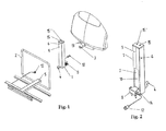
- Fig. 1 shows a lifting device 1 for a bicycle carrier 2 and the rear side of a car.
- Lifting device 1 en bicycle carrier 2 are to be fastened to the towing hook 3 at the rear side of a car (not further illustrated).
- the usual stabilisation-device at the towing hook 3 that serves for the horizontal stabilisation of the lifting device 1 and the bicycle carrier 2, is also not shown.
- Fig. 2 shows the lifting device 1 in more detail.
- the lifting device comprises a first column 6, permanently connected to which is a towing hook 4.
- the bicycle carrier 2 is provided with a coupling mechanism 5 with which the bicycle carrier can be fastened to the towing hook 4 of the lifting device.
- Within column 6 a second column 7 is provided that is slidable in the direction of the longitudinal axis of column 6.
- Column 7 is provided with a projecting coupling mechanism 8 for coupling the lifting device 1 to the towing hook 3 of the car.
- Towing hook 3 of the car and towing 4 hook of the lifting device 1 are similar towing hooks.
- the coupling mechanism 5 of the bicycle carrier 2 and the coupling mechanism 8 of the lifting device 1 are also similar coupling mechanisms. These are standard and are available in the market and will not be described in further detail.
- the coupling mechanism 8 and the towing hook 4 are located at opposite sides of the lifting device 1.
- the actuator 10 is permanently fixed to column 7. By means of the actuator 10 the rod 9 is movable in its longitudinal direction. The free end of rod 9 is fastened to column 6, at the inside of the upper surface of column 6.
- the actuator 10 comprises an electromotor that is powered from the power supply of the car and is connected thereto by means of a plug 12 of the lifting device and the socket outlet 13 of the car.
- the plug 12 is also connected with socket outlet 14 of the lifting device.
- the socket outlet 14 belongs to the towing hook 4 of the lifting device and serves, for example, for connecting the lighting (not shown) of the bicycle carrier 2.
- the actuator 10 is further provided with a detent that fixes the position of the rod 9 when the same is not being moved by the actuator.
- the actuator 10 is connected with control switches 15 and 15', mounted to the outside of lid 11 of column 7.
- the control switch 15 serves for moving column 7 upward in relation to column 6.
- the control switch 15' serves for moving column 7 downward in relation to column 6.
- a detent When none of the two switches is operated, the mutual position of column 7 and column 6 is fixed by a detent.
- This detent may be embodied in numerous different ways that are not new in themselves. With most of the threaded spindles and ball circulating screws, for example, a separate detent is not required. When the spill of the ball circulating screw is not rotated, the detent function is fulfilled by the internal friction and thus the detent is inherently provided in the spindle.
- swivel casters At the lower side of column 6, finally, swivel casters (not shown) are mounted.
- the lifting device is used as follows. If this has not been done already, the bicycle carrier 2 is first fastened to the lifting device 1 by coupling the coupling mechanism 5 to the towing hook 4 of the lifting device 1.
- the towing hook 4 is fastened to the column 6 in such a manner that when the lifting device is standing on the ground, the bicycle carrier 2 is positioned on or just above the ground. It is now very easy to place one or several bicycles on the bicycle carrier 2. They may be directly wheeled on and require no or hardly any lifting and manoeuvring. Once the bicycles are placed and secured on the bicycle carrier 2 this assembly of lifting device 1, bicycle carrier 2, and the bicycles is wheeled to the car, making use of the swivel casters.
- the plug 12 is plugged into the socket outlet 13 to supply actuator 10 with electricity.
- the column 7 is moved upwards until the coupling mechanism 8 is located just above the level of the towing hook 3.
- the assembly is then moved in the horizontal direction until the coupling mechanism 8 is positioned directly above the towing hook 3.
- column 7 is moved downward in relation to column 6 until the mechanism 8 is coupled with the towing hook 3 is realised.
- the switch 15' By holding the switch 15', the column 6 with the bicycle carrier 2 fastened thereto is lifted off the ground. When there is sufficient space between the ground and column 6 and bicycle carrier 2, the switch 15' is released and the current position is maintained.
- the lifting device 1 is in addition equipped with an extra safeguard in the form of an extra mechanical lock to maintain the mutual position of column 6 and column 7.
- the lifting device 1 with the bicycle carrier 2 are now securely fastened to the car without any effort.
- Fig. 3 shows another embodiment of a lifting device according to the invention.
- column 6 is connected with a platform 17, under which 4 swivel casters 16 are provided.
- platform 17 has a larger dimension than the bottom side of column 6, the swivel casters 16 may be placed further apart from each other than in the embodiment of Fig. 1. This facilitates wheeling.
Landscapes
- Engineering & Computer Science (AREA)
- Mechanical Engineering (AREA)
- Fittings On The Vehicle Exterior For Carrying Loads, And Devices For Holding Or Mounting Articles (AREA)
Abstract
Description
- De invention relates to a lifting device for carriers such as bicycle carriers to be fastened to a vehicle, wherein the lifting device is provided with a first column, and a second column, which in a longitudinal direction is movably connected with the first column, and with moving-means for moving the first column and the second column in relation to each other. De invention also relates to a bicycle carrier and to a vehicle provided with such a lifting device.
- It should be noted that when referring in this application to a bicycle carrier, this also refers to other carriers that can be fastened to a vehicle. The invention is therefore equally applicable to other carriers, such as carriers for mopeds, scooters, wheelchairs, transport cases and the like.
- There are lifting devices known for mounting behind vehicles. These lifting devices are usually permanently fastened to the vehicle and serve, for example, for loading and unloading goods from a lorry.
- Also known are carriers for motorcycles, scooters and the like, provided with a lifting device. Sometimes these carriers with lifting device are removably fastened to a vehicle. However, to fasten the known carriers with lifting device to and/or detach the carrier form the vehicle, requires some know-how and should be performed by a skilled person with the aid of tools.
- The
American Patent Application US 5.011.361 discloses a carrier for scooters for disabled persons, which carrier is to be fastened to a motor vehicle. The carrier is provided with a mast with power lift, moving a platform between a lowered and a raised position. This carrier is heavy and is fastened to the chassis of a vehicle. - The
German Patent Application DE 196 08 334 relates to an extra load carrier for motor vehicles, for the transport of loads, in particular of motorcycles, comprising a carrier frame that can be raised and lowered and that is fastened to the chassis of the vehicle by means of two adapters. Fastening this carrier requires know-how and needs to be carried out by a skilled person. - It is therefore an object of the present invention to provide a lifting device for bicycle carriers to be fastened to a car, and which can be fastened to a car and removed therefrom by an ordinary driver of a car, and which allows a bicycle carrier to be mounted to a car, and bicycles to be fastened to the bicycle carrier without much effort in a simple and effective manner.
- This object is achieved with a lifting device for a carrier such as a bicycle carrier to be fastened to a vehicle, wherein the lifting device is provided with a first column and a second column, which in a longitudinal direction is movably connected with the first column, and with moving means for moving the first column and the second column in relation to each other, (wherein the lifting device is provided with a stop mechanism, for fixing a mutual position of the first column and the second column), wherein the first column near the lower end is provided with a first coupling piece for removably coupling the a bicycle carrier to the first column, and the second column is provided with a second coupling piece for removably coupling the lifting device to a towing hook of the vehicle. It is possible to mount a bicycle carrier to such a lifting device beforehand. This is mounted with the aid of a first coupling piece located close to the ground so that the bicycle carrier does not, or only slightly, need to be lifted. During mounting, this same may rest completely or partly on the ground so that mounting can take place without much effort. During use, the lifting device may then be taken to the vehicle with the bicycle carrier mounted thereon. The lifting device then rests on the ground near the towing hook of the vehicle. With the aid of the moving means, the second column with the second coupling piece is moved upward and manoeuvred above the towing hook. As the lifting device rests on the ground, this manoeuvre is relatively easy and requires no effort. With the aid of the moving means, the second column with the second coupling piece is subsequently moved downwards, over the towing hook and fixed thereto in the usual manner. Instead of mounting the lifting device with the bicycle carrier it is also possible to first mount the lifting device in the manner described above, and then mount the bicycle carrier to the lifting device, also in the manner described above.
- After that, the bicycle or bicycles are mounted to the bicycle carrier. As the bicycle carrier is still on or near the ground, this mounting is similarly simple and requires no effort and there is no need to manoeuvre a bicycle at a considerable height. With the aid of the moving means, the first column with the bicycle carrier and the bicycle(s) thereon is now moved upward in relations to the second column, which is presently fixed to the vehicle by means of the second coupling. After the bicycle carrier with the bicycle(s) has reached sufficient height the mutual position of the columns is detented. The detent may be embodied in any known manner. The assembly is now ready for transport without having to carry out any cumbersome manoeuvres with a bicycle carrier and with bicycles at an awkward height. Unloading takes place in reverse order. Of course, some of the actions may be carried out manually without making use of the advantages of the lifting device; for example, the lifting device may be fastened to the towing hook and the bicycle carrier to the lifting device at a low position. Subsequently, the bicycles are placed on the bicycle carrier and then the bicycle carrier with the bicycles are lifted to the correct height with the aid of the lifting device.
- It is especially advantageous if the moving means comprise an electromotor and are connectable to a power supply of the car, seeing as the socket outlet of the car is in the immediate vicinity of the towing hook. In a simple embodiment, the moving means are provided with a manual control. However, it is also advantageous that an embodiment of the invention wherein the moving means are provided with an electromotor also comprises moving means that can be operated manually. This may be used in case of power failure. In a preferred embodiment, the manual control is a crank.
- Examples of means that are suitable to generate a reciprocal movement as required in the moving means include a pneumatic cylinder, a hydraulic cylinder, a threaded spindle, a ball circulating screw, a rack, a chain, a drive belt, a steel cable, a combination of these.
- To facilitate transport of the lifting device from and to the vehicle, it is advantageous for the column to be provided at a lower side with at least one wheel. In this way the lifting device does not need to be carried, but may be wheeled. It is also possible to embody the carrier with wheels.
- Fastening a platform at the lower side of the column provided with at least three wheels renders the transport on wheels very stable. Such a platform may also be fastened to the carrier.
- Such a platform only serves for the transport to and from the car. Advantageously the platform is removable, especially if a relatively large platform is used. A lifting device according to the invention provided with wheels may, for example, be coupled to a bicycle carrier in a garage where it is immediately loaded with bicycles and after which the assembly of lifting device, bicycle carrier and bicycles is wheeled to the vehicle to be mounted in the manner described above.
- If the first coupling piece is provided with a towing hook, the device according to the invention is suitable for a bicycle carrier intended for coupling to a towing hook.
- Many bicycle carriers are provided with lighting that is connected to the socket outlet of the car at the towing hook. The lifting device of such bicycle carriers is advantageously provided with an electrical point for connecting both to the vehicle and to the bicycle carrier. This allows the plug of the bicycle carrier to be connected via the lifting device instead of leading a long flex around the same.
- The invention also applies to bicycle carriers that are embodied integrally with a lifting device according to the invention, as well as to vehicles embodied with a lifting device according to the invention.
- Hereinafter the invention will be further explained by way of non-limiting exemplary embodiments of the invention and with reference to the drawing, in which:
- Fig. 1 shows a perspective view of a bicycle carrier, lifting device according to the invention, and rear side of a car.
- Fig. 2 shows the lifting device of Fig. 1 in more detail, and
- Fig. 3 shows the lifting device of Figs. 1 and 2 on a mobile undercarriage.
- Fig. 1 shows a
lifting device 1 for abicycle carrier 2 and the rear side of a car.Lifting device 1 enbicycle carrier 2 are to be fastened to the towing hook 3 at the rear side of a car (not further illustrated). The usual stabilisation-device at the towing hook 3 that serves for the horizontal stabilisation of thelifting device 1 and thebicycle carrier 2, is also not shown. Fig. 2 shows thelifting device 1 in more detail. The lifting device comprises afirst column 6, permanently connected to which is a towing hook 4. Thebicycle carrier 2 is provided with acoupling mechanism 5 with which the bicycle carrier can be fastened to the towing hook 4 of the lifting device. Within column 6 asecond column 7 is provided that is slidable in the direction of the longitudinal axis ofcolumn 6.Column 7 is provided with aprojecting coupling mechanism 8 for coupling thelifting device 1 to the towing hook 3 of the car. Towing hook 3 of the car and towing 4 hook of thelifting device 1 are similar towing hooks. Thecoupling mechanism 5 of thebicycle carrier 2 and thecoupling mechanism 8 of thelifting device 1 are also similar coupling mechanisms. These are standard and are available in the market and will not be described in further detail. Thecoupling mechanism 8 and the towing hook 4 are located at opposite sides of thelifting device 1. Theactuator 10 is permanently fixed tocolumn 7. By means of theactuator 10 therod 9 is movable in its longitudinal direction. The free end ofrod 9 is fastened tocolumn 6, at the inside of the upper surface ofcolumn 6. As power source, theactuator 10 comprises an electromotor that is powered from the power supply of the car and is connected thereto by means of aplug 12 of the lifting device and thesocket outlet 13 of the car. Theplug 12 is also connected withsocket outlet 14 of the lifting device. Thesocket outlet 14 belongs to the towing hook 4 of the lifting device and serves, for example, for connecting the lighting (not shown) of thebicycle carrier 2. Theactuator 10 is further provided with a detent that fixes the position of therod 9 when the same is not being moved by the actuator. Theactuator 10 is connected withcontrol switches 15 and 15', mounted to the outside of lid 11 ofcolumn 7. Thecontrol switch 15 serves for movingcolumn 7 upward in relation tocolumn 6. The control switch 15' serves for movingcolumn 7 downward in relation tocolumn 6. When none of the two switches is operated, the mutual position ofcolumn 7 andcolumn 6 is fixed by a detent. This detent may be embodied in numerous different ways that are not new in themselves. With most of the threaded spindles and ball circulating screws, for example, a separate detent is not required. When the spill of the ball circulating screw is not rotated, the detent function is fulfilled by the internal friction and thus the detent is inherently provided in the spindle. At the lower side ofcolumn 6, finally, swivel casters (not shown) are mounted. - The lifting device is used as follows. If this has not been done already, the
bicycle carrier 2 is first fastened to thelifting device 1 by coupling thecoupling mechanism 5 to the towing hook 4 of thelifting device 1. The towing hook 4 is fastened to thecolumn 6 in such a manner that when the lifting device is standing on the ground, thebicycle carrier 2 is positioned on or just above the ground. It is now very easy to place one or several bicycles on thebicycle carrier 2. They may be directly wheeled on and require no or hardly any lifting and manoeuvring. Once the bicycles are placed and secured on thebicycle carrier 2 this assembly of liftingdevice 1,bicycle carrier 2, and the bicycles is wheeled to the car, making use of the swivel casters. At the car, theplug 12 is plugged into thesocket outlet 13 to supplyactuator 10 with electricity. With the aid ofswitch 15 thecolumn 7 is moved upwards until thecoupling mechanism 8 is located just above the level of the towing hook 3. With the aid of theswivel casters 16 the assembly is then moved in the horizontal direction until thecoupling mechanism 8 is positioned directly above the towing hook 3. By operating the switch 15',column 7 is moved downward in relation tocolumn 6 until themechanism 8 is coupled with the towing hook 3 is realised. By holding the switch 15', thecolumn 6 with thebicycle carrier 2 fastened thereto is lifted off the ground. When there is sufficient space between the ground andcolumn 6 andbicycle carrier 2, the switch 15' is released and the current position is maintained. Thelifting device 1 is in addition equipped with an extra safeguard in the form of an extra mechanical lock to maintain the mutual position ofcolumn 6 andcolumn 7. Thelifting device 1 with thebicycle carrier 2 are now securely fastened to the car without any effort. - Fig. 3 shows another embodiment of a lifting device according to the invention. By means of a snap fastening,
column 6 is connected with aplatform 17, under which 4swivel casters 16 are provided. Asplatform 17 has a larger dimension than the bottom side ofcolumn 6, theswivel casters 16 may be placed further apart from each other than in the embodiment of Fig. 1. This facilitates wheeling. When the assembly of liftingdevice 1,bicycle carrier 2 andplatform 17 are fastened to the car, the snap fastening betweencolumn 6 and theplatform 17 is released and the latter stowed away. - Of course, it is also possible to provide a lifting device according to the invention with a
platform 17 that is permanently fixed tocolumn 6. In addition, the above-described exemplary embodiments may be modified and altered in numerous ways without departing from the scope of the invention as laid down in the appended claims.
Claims (13)
- A lifting device (1) for a carrier such as a bicycle carrier (2) to be fastened to a vehicle, wherein the lifting device is provided with a first column, and a second column, which in a longitudinal direction is movably connected with the first column (6), and with moving means (9,10) for moving the first column (6) and the second column (7) in relation to each other, (wherein the lifting device (1) is provided with a detent, for fixing a mutual position of the first column (6) and the second column (7)), characterised in that the first column (6) near the lower end is provided with a first coupling piece (4) for removably coupling the a bicycle carrier (2) to the first column (6), and the second column (7) is provided with a second coupling piece (8) for removably coupling the lifting device (1) to a towing hook (3) of the vehicle.
- A lifting device (1) according to claim 1, characterised in that the moving means (9,10) comprise an electromotor.
- A lifting device (1) according to claim 2, characterised in that the moving means (9,10) are connectable to a power supply (13) of the car.
- A lifting device (1) according to one of the claims 1 to 3, characterised in that the moving means (9,10) are comprised of one of the group consisting of a pneumatic cylinder, a hydraulic cylinder, a threaded spindle, a ball circulating screw, a rack, a chain, a drive belt, a steel cable, a combination of these.
- A lifting device according to one of the claims 1 to 4, characterised in that the moving means (9,10) are provided with a manual control.
- A lifting device according to claim 5, characterised in that the manual control is a crank.
- A lifting device (1) according to one of the claims 1 to 6, characterised in that the column (6) is provided at a lower side with at least one wheel (16).
- A lifting device (1) according to one of the claims 1 to 7, characterised in that a platform (17) is fastened to the lower side of the column (6), which is provided with at least three wheels (16).
- A lifting device (1) according to claim 8, characterised in that the platform (17) is removable.
- A lifting device (1) according to one of the claims 1 to 9, characterised in that the first coupling piece (4) is provided with a towing hook.
- A lifting device (1) according to one of the claims 1 to 10, characterised in that the lifting device (1) is provided with a power connection (12,14) to be connected both to the vehicle and to the bicycle carrier (14).
- A bicycle carrier (2) provided with a lifting device (1) according to one of the claims 1 to 11.
- A vehicle provided with a lifting device (1) according to one of the claims 1 to 11.
Applications Claiming Priority (1)
| Application Number | Priority Date | Filing Date | Title |
|---|---|---|---|
| NL1031124A NL1031124C2 (en) | 2006-02-10 | 2006-02-10 | Lifting device for a bicycle carrier, and bicycle carrier and vehicle with this lifting device. |
Publications (2)
| Publication Number | Publication Date |
|---|---|
| EP1818219A1 true EP1818219A1 (en) | 2007-08-15 |
| EP1818219B1 EP1818219B1 (en) | 2011-06-29 |
Family
ID=36572001
Family Applications (1)
| Application Number | Title | Priority Date | Filing Date |
|---|---|---|---|
| EP07102039A Not-in-force EP1818219B1 (en) | 2006-02-10 | 2007-02-09 | Lifting device for a bicycle carrier |
Country Status (3)
| Country | Link |
|---|---|
| EP (1) | EP1818219B1 (en) |
| AT (1) | ATE514595T1 (en) |
| NL (1) | NL1031124C2 (en) |
Cited By (3)
| Publication number | Priority date | Publication date | Assignee | Title |
|---|---|---|---|---|
| EP2338740A1 (en) | 2009-12-28 | 2011-06-29 | Qarden B.V. | Device for carrying a bicycle, to be attached to a vehicle |
| EP4137335A1 (en) * | 2021-08-17 | 2023-02-22 | Thomas Breinig | Coupling attachment for a ball head coupling of a motor vehicle and method for transporting at least one transport material by means of a coupling attachment |
| US12570506B1 (en) | 2024-09-12 | 2026-03-10 | Nick Konopacki | System and method for hitch rack carrying apparatus |
Families Citing this family (2)
| Publication number | Priority date | Publication date | Assignee | Title |
|---|---|---|---|---|
| DE102013020580A1 (en) * | 2013-12-13 | 2015-06-18 | Harald Genal | "Carrier" |
| DE102020207766B3 (en) | 2020-06-23 | 2021-11-25 | Volkswagen Aktiengesellschaft | Transport device for two-wheelers |
Citations (7)
| Publication number | Priority date | Publication date | Assignee | Title |
|---|---|---|---|---|
| US5011361A (en) | 1988-10-27 | 1991-04-30 | Peterson Edward A | Vehicle mountable carrier for three-wheeled scooter and the like |
| FR2689468A1 (en) * | 1991-10-28 | 1993-10-08 | Lebee Gerard | Cycle carrier e.g. for motor vehicles - has vertical post attached to rear of vehicle and supporting a rectangular frame |
| US5431522A (en) | 1994-06-14 | 1995-07-11 | Ross; Robert E. | Low profile scooter holder |
| DE19608334A1 (en) | 1996-03-05 | 1997-09-11 | Thomas Raithel | Load support for vehicle, especially for carrying motorcycles |
| US5816763A (en) * | 1997-05-13 | 1998-10-06 | Mobility Cart Lifts, Llc | Apparatus for transporting mobility devices and method therefor |
| EP0710588B1 (en) | 1994-11-04 | 1999-01-07 | Industri AB Thule | An apparatus for securing a load carrier to the ball hitch of a vehicle |
| US20020005422A1 (en) * | 1998-08-21 | 2002-01-17 | Neil Nusbaum | Universal bicycle rack using a seat post clamp |
-
2006
- 2006-02-10 NL NL1031124A patent/NL1031124C2/en not_active IP Right Cessation
-
2007
- 2007-02-09 AT AT07102039T patent/ATE514595T1/en not_active IP Right Cessation
- 2007-02-09 EP EP07102039A patent/EP1818219B1/en not_active Not-in-force
Patent Citations (7)
| Publication number | Priority date | Publication date | Assignee | Title |
|---|---|---|---|---|
| US5011361A (en) | 1988-10-27 | 1991-04-30 | Peterson Edward A | Vehicle mountable carrier for three-wheeled scooter and the like |
| FR2689468A1 (en) * | 1991-10-28 | 1993-10-08 | Lebee Gerard | Cycle carrier e.g. for motor vehicles - has vertical post attached to rear of vehicle and supporting a rectangular frame |
| US5431522A (en) | 1994-06-14 | 1995-07-11 | Ross; Robert E. | Low profile scooter holder |
| EP0710588B1 (en) | 1994-11-04 | 1999-01-07 | Industri AB Thule | An apparatus for securing a load carrier to the ball hitch of a vehicle |
| DE19608334A1 (en) | 1996-03-05 | 1997-09-11 | Thomas Raithel | Load support for vehicle, especially for carrying motorcycles |
| US5816763A (en) * | 1997-05-13 | 1998-10-06 | Mobility Cart Lifts, Llc | Apparatus for transporting mobility devices and method therefor |
| US20020005422A1 (en) * | 1998-08-21 | 2002-01-17 | Neil Nusbaum | Universal bicycle rack using a seat post clamp |
Cited By (3)
| Publication number | Priority date | Publication date | Assignee | Title |
|---|---|---|---|---|
| EP2338740A1 (en) | 2009-12-28 | 2011-06-29 | Qarden B.V. | Device for carrying a bicycle, to be attached to a vehicle |
| EP4137335A1 (en) * | 2021-08-17 | 2023-02-22 | Thomas Breinig | Coupling attachment for a ball head coupling of a motor vehicle and method for transporting at least one transport material by means of a coupling attachment |
| US12570506B1 (en) | 2024-09-12 | 2026-03-10 | Nick Konopacki | System and method for hitch rack carrying apparatus |
Also Published As
| Publication number | Publication date |
|---|---|
| EP1818219B1 (en) | 2011-06-29 |
| ATE514595T1 (en) | 2011-07-15 |
| NL1031124C2 (en) | 2007-08-14 |
Similar Documents
| Publication | Publication Date | Title |
|---|---|---|
| CN104709847B (en) | A kind of self-balancing type Multifunctional carrier | |
| US8235644B2 (en) | Personal mobility vehicle lift | |
| US7771155B2 (en) | Multi-lift for lifting and storing motorcycles and other vehicles | |
| US20090041564A1 (en) | Powered hand truck | |
| US9937088B2 (en) | Automotive wheelchair storage device | |
| EP1829815B1 (en) | A forklift truck | |
| US8910957B1 (en) | Self-loading mini dolly | |
| JP2008536779A (en) | Equipment for lifting, handling and transporting containers | |
| CN106809768B (en) | Hand-push type foldable boom loading and unloading vehicle | |
| US20070172341A1 (en) | Container driver | |
| US20040247423A1 (en) | Multi-lift for lifting and storing motorcycles and other vehicles | |
| EP1818219B1 (en) | Lifting device for a bicycle carrier | |
| US20020164239A1 (en) | Tiltable cargo box assembly with extension ramp | |
| US20070059135A1 (en) | Truck fork attachment including adjustable mast for ground clearance | |
| CN204529227U (en) | A kind of Multifunctional carrier | |
| AU2024278324B2 (en) | Tire handler having tire lay flat capability | |
| US6007290A (en) | Liftable dual cargo platforms for a motor home | |
| US20050212237A1 (en) | Wheelbarrow having an auxiliary rear wheel assembly | |
| US9340397B1 (en) | Illuminated vehicle lift assembly | |
| US20100038181A1 (en) | Portable lift | |
| US8322968B1 (en) | Fork lift for trucks, methods, and associated devices | |
| US20040213655A1 (en) | Powered trailer hitch attachment | |
| US4103799A (en) | Multi-purpose working vehicle | |
| US20240300270A1 (en) | Jack hitch system and device | |
| US20230124326A1 (en) | Lifting device |
Legal Events
| Date | Code | Title | Description |
|---|---|---|---|
| PUAI | Public reference made under article 153(3) epc to a published international application that has entered the european phase |
Free format text: ORIGINAL CODE: 0009012 |
|
| AK | Designated contracting states |
Kind code of ref document: A1 Designated state(s): AT BE BG CH CY CZ DE DK EE ES FI FR GB GR HU IE IS IT LI LT LU LV MC NL PL PT RO SE SI SK TR |
|
| AX | Request for extension of the european patent |
Extension state: AL BA HR MK YU |
|
| 17P | Request for examination filed |
Effective date: 20080215 |
|
| 17Q | First examination report despatched |
Effective date: 20080317 |
|
| AKX | Designation fees paid |
Designated state(s): AT BE BG CH CY CZ DE DK EE ES FI FR GB GR HU IE IS IT LI LT LU LV MC NL PL PT RO SE SI SK TR |
|
| RTI1 | Title (correction) |
Free format text: LIFTING DEVICE FOR A BICYCLE CARRIER |
|
| GRAP | Despatch of communication of intention to grant a patent |
Free format text: ORIGINAL CODE: EPIDOSNIGR1 |
|
| GRAS | Grant fee paid |
Free format text: ORIGINAL CODE: EPIDOSNIGR3 |
|
| GRAA | (expected) grant |
Free format text: ORIGINAL CODE: 0009210 |
|
| RAP1 | Party data changed (applicant data changed or rights of an application transferred) |
Owner name: DOGE COLLECTION |
|
| AK | Designated contracting states |
Kind code of ref document: B1 Designated state(s): AT BE BG CH CY CZ DE DK EE ES FI FR GB GR HU IE IS IT LI LT LU LV MC NL PL PT RO SE SI SK TR |
|
| REG | Reference to a national code |
Ref country code: GB Ref legal event code: FG4D |
|
| REG | Reference to a national code |
Ref country code: CH Ref legal event code: EP |
|
| REG | Reference to a national code |
Ref country code: IE Ref legal event code: FG4D |
|
| REG | Reference to a national code |
Ref country code: DE Ref legal event code: R096 Ref document number: 602007015467 Country of ref document: DE Effective date: 20110818 |
|
| REG | Reference to a national code |
Ref country code: NL Ref legal event code: T3 |
|
| PG25 | Lapsed in a contracting state [announced via postgrant information from national office to epo] |
Ref country code: LT Free format text: LAPSE BECAUSE OF FAILURE TO SUBMIT A TRANSLATION OF THE DESCRIPTION OR TO PAY THE FEE WITHIN THE PRESCRIBED TIME-LIMIT Effective date: 20110629 Ref country code: SE Free format text: LAPSE BECAUSE OF FAILURE TO SUBMIT A TRANSLATION OF THE DESCRIPTION OR TO PAY THE FEE WITHIN THE PRESCRIBED TIME-LIMIT Effective date: 20110629 |
|
| PG25 | Lapsed in a contracting state [announced via postgrant information from national office to epo] |
Ref country code: LV Free format text: LAPSE BECAUSE OF FAILURE TO SUBMIT A TRANSLATION OF THE DESCRIPTION OR TO PAY THE FEE WITHIN THE PRESCRIBED TIME-LIMIT Effective date: 20110629 Ref country code: GR Free format text: LAPSE BECAUSE OF FAILURE TO SUBMIT A TRANSLATION OF THE DESCRIPTION OR TO PAY THE FEE WITHIN THE PRESCRIBED TIME-LIMIT Effective date: 20110930 Ref country code: AT Free format text: LAPSE BECAUSE OF FAILURE TO SUBMIT A TRANSLATION OF THE DESCRIPTION OR TO PAY THE FEE WITHIN THE PRESCRIBED TIME-LIMIT Effective date: 20110629 Ref country code: FI Free format text: LAPSE BECAUSE OF FAILURE TO SUBMIT A TRANSLATION OF THE DESCRIPTION OR TO PAY THE FEE WITHIN THE PRESCRIBED TIME-LIMIT Effective date: 20110629 Ref country code: SI Free format text: LAPSE BECAUSE OF FAILURE TO SUBMIT A TRANSLATION OF THE DESCRIPTION OR TO PAY THE FEE WITHIN THE PRESCRIBED TIME-LIMIT Effective date: 20110629 |
|
| PG25 | Lapsed in a contracting state [announced via postgrant information from national office to epo] |
Ref country code: CZ Free format text: LAPSE BECAUSE OF FAILURE TO SUBMIT A TRANSLATION OF THE DESCRIPTION OR TO PAY THE FEE WITHIN THE PRESCRIBED TIME-LIMIT Effective date: 20110629 Ref country code: PT Free format text: LAPSE BECAUSE OF FAILURE TO SUBMIT A TRANSLATION OF THE DESCRIPTION OR TO PAY THE FEE WITHIN THE PRESCRIBED TIME-LIMIT Effective date: 20111031 Ref country code: IS Free format text: LAPSE BECAUSE OF FAILURE TO SUBMIT A TRANSLATION OF THE DESCRIPTION OR TO PAY THE FEE WITHIN THE PRESCRIBED TIME-LIMIT Effective date: 20111029 Ref country code: EE Free format text: LAPSE BECAUSE OF FAILURE TO SUBMIT A TRANSLATION OF THE DESCRIPTION OR TO PAY THE FEE WITHIN THE PRESCRIBED TIME-LIMIT Effective date: 20110629 |
|
| PG25 | Lapsed in a contracting state [announced via postgrant information from national office to epo] |
Ref country code: CY Free format text: LAPSE BECAUSE OF FAILURE TO SUBMIT A TRANSLATION OF THE DESCRIPTION OR TO PAY THE FEE WITHIN THE PRESCRIBED TIME-LIMIT Effective date: 20110629 Ref country code: RO Free format text: LAPSE BECAUSE OF FAILURE TO SUBMIT A TRANSLATION OF THE DESCRIPTION OR TO PAY THE FEE WITHIN THE PRESCRIBED TIME-LIMIT Effective date: 20110629 Ref country code: SK Free format text: LAPSE BECAUSE OF FAILURE TO SUBMIT A TRANSLATION OF THE DESCRIPTION OR TO PAY THE FEE WITHIN THE PRESCRIBED TIME-LIMIT Effective date: 20110629 Ref country code: PL Free format text: LAPSE BECAUSE OF FAILURE TO SUBMIT A TRANSLATION OF THE DESCRIPTION OR TO PAY THE FEE WITHIN THE PRESCRIBED TIME-LIMIT Effective date: 20110629 |
|
| PLBE | No opposition filed within time limit |
Free format text: ORIGINAL CODE: 0009261 |
|
| STAA | Information on the status of an ep patent application or granted ep patent |
Free format text: STATUS: NO OPPOSITION FILED WITHIN TIME LIMIT |
|
| PG25 | Lapsed in a contracting state [announced via postgrant information from national office to epo] |
Ref country code: IT Free format text: LAPSE BECAUSE OF FAILURE TO SUBMIT A TRANSLATION OF THE DESCRIPTION OR TO PAY THE FEE WITHIN THE PRESCRIBED TIME-LIMIT Effective date: 20110629 |
|
| 26N | No opposition filed |
Effective date: 20120330 |
|
| PG25 | Lapsed in a contracting state [announced via postgrant information from national office to epo] |
Ref country code: DK Free format text: LAPSE BECAUSE OF FAILURE TO SUBMIT A TRANSLATION OF THE DESCRIPTION OR TO PAY THE FEE WITHIN THE PRESCRIBED TIME-LIMIT Effective date: 20110629 |
|
| REG | Reference to a national code |
Ref country code: DE Ref legal event code: R097 Ref document number: 602007015467 Country of ref document: DE Effective date: 20120330 |
|
| PG25 | Lapsed in a contracting state [announced via postgrant information from national office to epo] |
Ref country code: MC Free format text: LAPSE BECAUSE OF NON-PAYMENT OF DUE FEES Effective date: 20120229 |
|
| REG | Reference to a national code |
Ref country code: CH Ref legal event code: PL |
|
| GBPC | Gb: european patent ceased through non-payment of renewal fee |
Effective date: 20120209 |
|
| PG25 | Lapsed in a contracting state [announced via postgrant information from national office to epo] |
Ref country code: CH Free format text: LAPSE BECAUSE OF NON-PAYMENT OF DUE FEES Effective date: 20120229 Ref country code: LI Free format text: LAPSE BECAUSE OF NON-PAYMENT OF DUE FEES Effective date: 20120229 |
|
| REG | Reference to a national code |
Ref country code: IE Ref legal event code: MM4A |
|
| REG | Reference to a national code |
Ref country code: FR Ref legal event code: ST Effective date: 20121031 |
|
| PG25 | Lapsed in a contracting state [announced via postgrant information from national office to epo] |
Ref country code: FR Free format text: LAPSE BECAUSE OF NON-PAYMENT OF DUE FEES Effective date: 20120229 Ref country code: GB Free format text: LAPSE BECAUSE OF NON-PAYMENT OF DUE FEES Effective date: 20120209 Ref country code: IE Free format text: LAPSE BECAUSE OF NON-PAYMENT OF DUE FEES Effective date: 20120209 |
|
| PG25 | Lapsed in a contracting state [announced via postgrant information from national office to epo] |
Ref country code: ES Free format text: LAPSE BECAUSE OF FAILURE TO SUBMIT A TRANSLATION OF THE DESCRIPTION OR TO PAY THE FEE WITHIN THE PRESCRIBED TIME-LIMIT Effective date: 20111010 |
|
| PG25 | Lapsed in a contracting state [announced via postgrant information from national office to epo] |
Ref country code: BG Free format text: LAPSE BECAUSE OF FAILURE TO SUBMIT A TRANSLATION OF THE DESCRIPTION OR TO PAY THE FEE WITHIN THE PRESCRIBED TIME-LIMIT Effective date: 20110929 |
|
| PG25 | Lapsed in a contracting state [announced via postgrant information from national office to epo] |
Ref country code: TR Free format text: LAPSE BECAUSE OF FAILURE TO SUBMIT A TRANSLATION OF THE DESCRIPTION OR TO PAY THE FEE WITHIN THE PRESCRIBED TIME-LIMIT Effective date: 20110629 |
|
| PG25 | Lapsed in a contracting state [announced via postgrant information from national office to epo] |
Ref country code: LU Free format text: LAPSE BECAUSE OF NON-PAYMENT OF DUE FEES Effective date: 20120209 |
|
| PG25 | Lapsed in a contracting state [announced via postgrant information from national office to epo] |
Ref country code: HU Free format text: LAPSE BECAUSE OF FAILURE TO SUBMIT A TRANSLATION OF THE DESCRIPTION OR TO PAY THE FEE WITHIN THE PRESCRIBED TIME-LIMIT Effective date: 20070209 |
|
| PGFP | Annual fee paid to national office [announced via postgrant information from national office to epo] |
Ref country code: NL Payment date: 20170326 Year of fee payment: 11 |
|
| PGFP | Annual fee paid to national office [announced via postgrant information from national office to epo] |
Ref country code: BE Payment date: 20170327 Year of fee payment: 11 |
|
| PGFP | Annual fee paid to national office [announced via postgrant information from national office to epo] |
Ref country code: DE Payment date: 20170329 Year of fee payment: 11 |
|
| REG | Reference to a national code |
Ref country code: DE Ref legal event code: R119 Ref document number: 602007015467 Country of ref document: DE |
|
| REG | Reference to a national code |
Ref country code: NL Ref legal event code: MM Effective date: 20180301 |
|
| REG | Reference to a national code |
Ref country code: BE Ref legal event code: MM Effective date: 20180228 |
|
| PG25 | Lapsed in a contracting state [announced via postgrant information from national office to epo] |
Ref country code: NL Free format text: LAPSE BECAUSE OF NON-PAYMENT OF DUE FEES Effective date: 20180301 |
|
| PG25 | Lapsed in a contracting state [announced via postgrant information from national office to epo] |
Ref country code: DE Free format text: LAPSE BECAUSE OF NON-PAYMENT OF DUE FEES Effective date: 20180901 |
|
| PG25 | Lapsed in a contracting state [announced via postgrant information from national office to epo] |
Ref country code: BE Free format text: LAPSE BECAUSE OF NON-PAYMENT OF DUE FEES Effective date: 20180228 |