EP1818205A1 - Shift operating device for traveling vehicle - Google Patents
Shift operating device for traveling vehicle Download PDFInfo
- Publication number
- EP1818205A1 EP1818205A1 EP04788242A EP04788242A EP1818205A1 EP 1818205 A1 EP1818205 A1 EP 1818205A1 EP 04788242 A EP04788242 A EP 04788242A EP 04788242 A EP04788242 A EP 04788242A EP 1818205 A1 EP1818205 A1 EP 1818205A1
- Authority
- EP
- European Patent Office
- Prior art keywords
- traveling pedal
- shift operating
- rearward
- arm
- pedal
- Prior art date
- Legal status (The legal status is an assumption and is not a legal conclusion. Google has not performed a legal analysis and makes no representation as to the accuracy of the status listed.)
- Withdrawn
Links
- 238000009434 installation Methods 0.000 claims abstract description 37
- 230000007935 neutral effect Effects 0.000 claims description 21
- 230000001105 regulatory effect Effects 0.000 claims description 8
- 238000010276 construction Methods 0.000 description 16
- 238000000034 method Methods 0.000 description 4
- 238000004519 manufacturing process Methods 0.000 description 3
- 230000005540 biological transmission Effects 0.000 description 2
- 230000000694 effects Effects 0.000 description 1
- ZZUFCTLCJUWOSV-UHFFFAOYSA-N furosemide Chemical compound C1=C(Cl)C(S(=O)(=O)N)=CC(C(O)=O)=C1NCC1=CC=CO1 ZZUFCTLCJUWOSV-UHFFFAOYSA-N 0.000 description 1
- 230000002706 hydrostatic effect Effects 0.000 description 1
- 230000009347 mechanical transmission Effects 0.000 description 1
Images




Classifications
-
- G—PHYSICS
- G05—CONTROLLING; REGULATING
- G05G—CONTROL DEVICES OR SYSTEMS INSOFAR AS CHARACTERISED BY MECHANICAL FEATURES ONLY
- G05G1/00—Controlling members, e.g. knobs or handles; Assemblies or arrangements thereof; Indicating position of controlling members
- G05G1/30—Controlling members actuated by foot
- G05G1/36—Mounting units comprising an assembly of two or more pedals, e.g. for facilitating mounting
-
- F—MECHANICAL ENGINEERING; LIGHTING; HEATING; WEAPONS; BLASTING
- F16—ENGINEERING ELEMENTS AND UNITS; GENERAL MEASURES FOR PRODUCING AND MAINTAINING EFFECTIVE FUNCTIONING OF MACHINES OR INSTALLATIONS; THERMAL INSULATION IN GENERAL
- F16H—GEARING
- F16H59/00—Control inputs to control units of change-speed- or reversing-gearings for conveying rotary motion
- F16H59/02—Selector apparatus
- F16H59/04—Ratio selector apparatus
- F16H59/06—Ratio selector apparatus the ratio being infinitely variable
-
- F—MECHANICAL ENGINEERING; LIGHTING; HEATING; WEAPONS; BLASTING
- F16—ENGINEERING ELEMENTS AND UNITS; GENERAL MEASURES FOR PRODUCING AND MAINTAINING EFFECTIVE FUNCTIONING OF MACHINES OR INSTALLATIONS; THERMAL INSULATION IN GENERAL
- F16H—GEARING
- F16H61/00—Control functions within control units of change-speed- or reversing-gearings for conveying rotary motion ; Control of exclusively fluid gearing, friction gearing, gearings with endless flexible members or other particular types of gearing
- F16H61/38—Control of exclusively fluid gearing
- F16H61/40—Control of exclusively fluid gearing hydrostatic
- F16H61/42—Control of exclusively fluid gearing hydrostatic involving adjustment of a pump or motor with adjustable output or capacity
-
- F—MECHANICAL ENGINEERING; LIGHTING; HEATING; WEAPONS; BLASTING
- F16—ENGINEERING ELEMENTS AND UNITS; GENERAL MEASURES FOR PRODUCING AND MAINTAINING EFFECTIVE FUNCTIONING OF MACHINES OR INSTALLATIONS; THERMAL INSULATION IN GENERAL
- F16H—GEARING
- F16H61/00—Control functions within control units of change-speed- or reversing-gearings for conveying rotary motion ; Control of exclusively fluid gearing, friction gearing, gearings with endless flexible members or other particular types of gearing
- F16H61/38—Control of exclusively fluid gearing
- F16H61/40—Control of exclusively fluid gearing hydrostatic
- F16H61/42—Control of exclusively fluid gearing hydrostatic involving adjustment of a pump or motor with adjustable output or capacity
- F16H61/427—Motor capacity control by mechanical control means, e.g. by levers or pedals
-
- G—PHYSICS
- G05—CONTROLLING; REGULATING
- G05G—CONTROL DEVICES OR SYSTEMS INSOFAR AS CHARACTERISED BY MECHANICAL FEATURES ONLY
- G05G1/00—Controlling members, e.g. knobs or handles; Assemblies or arrangements thereof; Indicating position of controlling members
- G05G1/30—Controlling members actuated by foot
- G05G1/46—Means, e.g. links, for connecting the pedal to the controlled unit
-
- B—PERFORMING OPERATIONS; TRANSPORTING
- B60—VEHICLES IN GENERAL
- B60K—ARRANGEMENT OR MOUNTING OF PROPULSION UNITS OR OF TRANSMISSIONS IN VEHICLES; ARRANGEMENT OR MOUNTING OF PLURAL DIVERSE PRIME-MOVERS IN VEHICLES; AUXILIARY DRIVES FOR VEHICLES; INSTRUMENTATION OR DASHBOARDS FOR VEHICLES; ARRANGEMENTS IN CONNECTION WITH COOLING, AIR INTAKE, GAS EXHAUST OR FUEL SUPPLY OF PROPULSION UNITS IN VEHICLES
- B60K17/00—Arrangement or mounting of transmissions in vehicles
- B60K17/04—Arrangement or mounting of transmissions in vehicles characterised by arrangement, location or kind of gearing
- B60K17/10—Arrangement or mounting of transmissions in vehicles characterised by arrangement, location or kind of gearing of fluid gearing
-
- F—MECHANICAL ENGINEERING; LIGHTING; HEATING; WEAPONS; BLASTING
- F16—ENGINEERING ELEMENTS AND UNITS; GENERAL MEASURES FOR PRODUCING AND MAINTAINING EFFECTIVE FUNCTIONING OF MACHINES OR INSTALLATIONS; THERMAL INSULATION IN GENERAL
- F16H—GEARING
- F16H59/00—Control inputs to control units of change-speed- or reversing-gearings for conveying rotary motion
- F16H59/02—Selector apparatus
- F16H2059/0234—Selectors for gearings using foot control
-
- Y—GENERAL TAGGING OF NEW TECHNOLOGICAL DEVELOPMENTS; GENERAL TAGGING OF CROSS-SECTIONAL TECHNOLOGIES SPANNING OVER SEVERAL SECTIONS OF THE IPC; TECHNICAL SUBJECTS COVERED BY FORMER USPC CROSS-REFERENCE ART COLLECTIONS [XRACs] AND DIGESTS
- Y10—TECHNICAL SUBJECTS COVERED BY FORMER USPC
- Y10T—TECHNICAL SUBJECTS COVERED BY FORMER US CLASSIFICATION
- Y10T74/00—Machine element or mechanism
- Y10T74/20—Control lever and linkage systems
- Y10T74/20012—Multiple controlled elements
- Y10T74/20018—Transmission control
- Y10T74/20055—Foot operated
- Y10T74/20061—Multiple foot-operated controls
Definitions
- the present invention relates to a shift operating device of a traveling vehicle.
- HST hydro static transmission
- a shift operating device in which a forward traveling pedal and a rearward traveling pedal are separately disposed, is provided (for example, see the Patent Literature 1).
- a rotary support shaft of the forward traveling pedal and a rotary support shaft of the rearward traveling pedal are provided while being shifted their positions, and each of the rotary support shafts is connected to a control arm through a linkage mechanism.
- the linkage mechanism rotates the control arm along the direction opposite to the case that the rearward traveling pedal is operated.
- Patent Literature 1 the US Patent No. 5842378
- Patent Literature 2 the US Patent No. 4759417
- the rotary support shafts of the forward traveling pedal and the rearward traveling pedal are provided while being shifted their positions, whereby the linkage mechanism is complicated.
- the angles of the pedals of the complicated linkage mechanism many adjustment processes are required. Part number is many and influences manufacturing cost and number of assemble processes.
- the rotary support shafts of the forward traveling pedal and the rearward traveling pedal are provided while being shifted their positions, it is difficult to secure arrangement space of the shafts in relation to the other devices.
- the conventional mechanism setting the neutral position of the pedals the structure is complicated. The power transmitted to the cam is dispersed at the contact point of the cam and the cam follower, whereby the transmission efficiency of biasing force of the neutral return spring is not good. Accordingly, the setting of the neutral position is inaccurate.
- the purpose of the invention is to simplify the linkage mechanism of a shift operating device and to unitize the shift operating device so as to improve the reliability of assemble accuracy.
- a forward traveling pedal and a rearward traveling pedal are rotatably supported by a installation plate;
- the installation plate rotatably supports a shift operating rotary sleeve connected through one link to the basal end of the forward traveling pedal and connected through one link to the basal end of the rearward traveling pedal;
- the forward traveling pedal, the rearward traveling pedal, the shift operating rotary sleeve and the installation plate are constructed as an integral unit; and the shift operating rotary sleeve is rotated forward and rearward interlockingly with the operation of the forward traveling pedal and the rearward traveling pedal so as to slant swash plates of a hydraulic pump and a hydraulic motor of a HST.
- the forward traveling pedal and the rearward traveling pedal are pivotally connected to a rotary support shaft supported by the installation plate.
- a neutral return mechanism which returns the forward traveling pedal and the rearward traveling pedal to a position at which tread amount is zero, is connected to the shift operating interlock rotary sleeve.
- a brake operation device is arranged on the installation plate.
- the shift operating device is interlockingly connected through a swash plate slant angle control mechanism to control arms of the hydraulic pump and the hydraulic motor of the HST
- the swash plate slant angle control mechanism comprises a first arm interlockingly connected to the control arm of the hydraulic motor and a second arm interlockingly connected to the control arm of the hydraulic pump, and the first and second arms are rotatably supported on a same axis and actuated interlockingly with each other.
- an angle regulation member regulating an extent of rotary angle of the second arm is provided in the swash plate slant angle control mechanism.
- a forward traveling pedal and a rearward traveling pedal are rotatably supported by a installation plate; the installation plate rotatably supports a shift operating rotary sleeve connected through one link to the basal end of the forward traveling pedal and connected through one link to the basal end of the rearward traveling pedal; the forward traveling pedal, the rearward traveling pedal, the shift operating rotary sleeve and the installation plate are constructed as an integral unit; and the shift operating rotary sleeve is rotated forward and rearward interlockingly with the operation of the forward traveling pedal and the rearward traveling pedal so as to slant swash plates of a hydraulic pump and a hydraulic motor of a HST.
- the shift operating device comprising the forward traveling pedal and the rearward traveling pedal is assembled as a unit, whereby the reliability of the assemble accuracy is improved.
- the link mechanism is simple so that the angle of the pedals can be adjusted easily.
- the forward traveling pedal and the rearward traveling pedal are pivotally connected to a rotary support shaft supported by the installation plate. Accordingly, compared with the conventional construction providing rotary support shafts respectively, the number of parts is reduced so as to reduce the manufacture cost and assemble processes. It is necessary to secure space for only one rotary support shaft, whereby the device is miniaturized.
- a neutral return mechanism which returns the forward traveling pedal and the rearward traveling pedal to a position at which tread amount is zero, is connected to the shift operating interlock rotary sleeve. Accordingly, the neutral position, at which the angles (slant angles about the floor) of the forward traveling pedal and the rearward traveling pedal are the same, can be adjusted easily and can be set with high accuracy.
- a brake operation device is arranged on the installation plate. Accordingly, the brake operation device is assembled as a unit, whereby the reliability of the assemble accuracy after imposing the device into the vehicle frame is improved.
- the shift operating device is interlockingly connected through a swash plate slant angle control mechanism to control arms of the hydraulic pump and the hydraulic motor of the HST
- the swash plate slant angle control mechanism comprises a first arm interlockingly connected to the control arm of the hydraulic motor and a second arm interlockingly connected to the control arm of the hydraulic pump, and the first and second arms are rotatably supported on a same axis and actuated interlockingly with each other.
- the hydraulic motor and the hydraulic pump are steplessly shifted interlockingly with each other by operating the shift operating device. Therefore, the shift operation is performed smoothly.
- the speed can be set optionally, whereby various setting of speed extends the extent of work.
- An angle regulation member regulating an extent of rotary angle of the second arm is provided in the swash plate slant angle control mechanism. Accordingly, the swash plate of the hydraulic pump is prevented from being slanted over the maximum slant angle, whereby the damage of the HST is prevented.
- a step 2 which is a footing for an operator is laid on a vehicle frame 1.
- an installation plate 3 on which various pedals are installed is laid before the step 2.
- a HST 4 is arranged below and behind the step 2.
- a gearbox 5 in which planetary gear mechanism is disposed is arranged behind the HST 4.
- the HST 4 and the planetary gear mechanism constitute HMT 6 (Hydro Mechanical Transmission).
- a brake operating device 10 is arranged at the left of the installation plate 3.
- the brake operating device 10 is provided therein with a left brake pedal 11, a right brake pedal 12, and a master brake pedal 13 for operating the brake pedals 11 and 12 simultaneously.
- the brake pedals 11 and 12 are interlockingly connected to a brake device (not shown) respectively through links 15 and 16.
- a shift operating device 20 which changes speed steplessly is disposed at the right of the installation plate 3.
- the shift operating device 20 is provided therein with a forward traveling pedal 21 and a rearward traveling pedal 22.
- the forward traveling pedal 21 and the rearward traveling pedal 22 are connected to a swash plate slant angle control mechanism 30 through a link 24.
- the swash plate slant angle control mechanism 30 is connected through a pump control link 42 to a control arm 52 of a hydraulic pump 4P and is connected through a motor control link 41 to a control arm 51 of a hydraulic motor 4M.
- a rotary support shaft 61 whose length is substantially the same as the lateral width of the installation plate 3, is provided laterally at the reverse side of the installation plate 3.
- the rotary support shaft 61 is hanged between a stay 3v projectingly provided in the left portion of the reverse side of the installation plate 3 and a stay 3y provided in the right portion thereof.
- the rotary support shaft 61 rotatably supports a left brake rotary sleeve 11 a to which the left brake pedal 11 is fixed, a right brake rotary sleeve 12a to which the right brake pedal 12 is fixed, and a master brake rotary sleeve 13a to which the master brake pedal 13 is fixed.
- the link 15 is connected to the right end of the left brake rotary sleeve 11 a, and the link 16 is connected to the right brake rotary sleeve 12a. Accordingly, each of the links 15 and 16 is operated independently following the operation of the left brake pedal 11 and the right brake pedal 12. By operating the master brake pedal 13, the left brake pedal 11 and the right brake pedal 12 are operated simultaneously, and the links 15 and 16 are operated interlockingly.
- a first rotary support shaft 71 is provided laterally oppositely to the shift operating device 20 about the installation plate 3.
- the first rotary support shaft 71 rotatably supports a forward traveling pedal rotary sleeve 21 a constituting the basal end of the forward traveling pedal 21 and a rearward traveling pedal rotary sleeve 22a constituting the basal end of the rearward traveling pedal 22.
- the first rotary support shaft 71 is supported by stays 3v and 3w projectingly provided in the reverse side of the installation plate 3.
- a second rotary support shaft 72 is provided laterally below the first rotary support shaft 71 in the installation plate 3.
- the second rotary support shaft 72 rotatably supports a shift operating rotary sleeve 73.
- the second rotary support shaft 72 is supported by stays 3v and 3x projectingly provided in the installation plate 3.
- An arm 21b is projectingly provided forward on the forward traveling pedal rotary sleeve 21a
- an arm 73f is projectingly provided forward on the shift operating rotary sleeve 73
- the arms 21b and 73f are connected to each other through a link 21c. Accordingly, by treading the forward traveling pedal 21, the shift operating rotary sleeve 73 is rotated clockwise in Fig. 4.
- the length of the link 21c is adjustable so as to adjust the angle of the forward traveling pedal 21.
- An arm 22b is projectingly provided forward on the forward traveling pedal rotary sleeve 21a, an arm 73b is projectingly provided rearward on the shift operating rotary sleeve 73, and the arm 22b and the arm 73b are connected to each other through a link 22c. Accordingly, by treading the rearward traveling pedal 22, the shift operating rotary sleeve 73 is rotated counterclockwise in Fig. 4. The length of the link 22c is adjustable so as to adjust the angle of the rearward traveling pedal 22.
- An arm 73m is projectingly provided downward on the shift operating rotary sleeve 73, and the projected end of the arm 73m is connected to the tip of the link 24.
- the link 24 is moved forward by operating the forward traveling pedal 21 and moved rearward by operating the rearward traveling pedal 22, whereby the later-discussed swash plate slant angle control mechanism 30 is interlockingly operated.
- An arm 73n is projectingly provided downward on the shift operating rotary sleeve 73, and the projected end of the arm 73n is connected to a rod 25a of a neutral return mechanism 25.
- the neutral return mechanism 25 is constructed as shown in Fig. 25.
- the rear end of the rod 25a is fixed to a front portion of a cylinder 25c, and a rod 25b is projected rearward from the cylinder 25c.
- the rear end of the rod 25b is connected to a stay 3a extended from the installation plate 3.
- a spring 25s is provided in the cylinder 25c so that the rod 25b is biased rearward by the biasing force of the spring 25s.
- the neutral return mechanism 25 is constructed as mentioned below.
- the spring 25s is freely fitted onto the rod 25b and interposed between a retaining ring 25m, touching the inner wall surface of the cylinder 25c at the left side in the drawing, and a retaining ring 25n, freely fitted onto the rod 25b.
- the left end of the rod 25b is projected leftward from the retaining ring 25m, and the projected end thereof is fixed to a retaining ring 25p.
- a double nut 25q is fastened onto the rod 25b so as to regulate the retaining ring 25n biased rightward by the spring 25s.
- a retaining ring 25k is fixed to the inner perimeter of the right end of the cylinder 25c. By making the left side surface of the retaining ring 25k touch the retaining ring 25n, the retaining ring 25n is prevented from falling out.
- the rod 25a is connected to the arm 73n through a link connection body 25u
- the rod 25b is connected to the stay 3a through a link connection body 25v.
- the link connection bodies 25u and 25v the lengths of the rods 25a and 25b (the projection length from the link connection bodies 25u and 25v) are adjustable so as to adjust the overall length of the neutral return mechanism 25 connecting the arm 73n and the stay 3 a.
- the angles of the forward traveling pedal 21 and the rearward traveling pedal 22 (the slant angles about the floor), interlocked with the angular position of the shift operating rotary sleeve 73, are adjusted.
- the angles of the pedals 21 and 22 in the neutral state can be equalized.
- the forward traveling pedal 21 and the rearward traveling pedal 22 are rotatably supported by the installation plate 3; the installation plate 3 rotatably supports the shift operating rotary sleeve 73 connected through one link 21c to the basal end of the forward traveling pedal 21 (the forward traveling pedal rotary sleeve 21a) and connected through one link 22c to the basal end of the rearward traveling pedal 22 (the rearward traveling pedal rotary sleeve 22a); the forward traveling pedal 21, the rearward traveling pedal 22, the shift operating rotary sleeve 73 and the installation plate 3 are constructed as an integral unit; and the shift operating rotary sleeve 73 is rotated forward and rearward interlockingly with the operation of the forward traveling pedal 21 and the rearward traveling pedal 22 so as to slant the swash plates of the hydraulic pump and the hydraulic motor of the HST 4.
- the shift operating device 20 comprising the forward traveling pedal 21 and the rearward traveling pedal 22 is assembled as a unit, whereby the reliability of the assemble accuracy after imposing the device into the vehicle frame 1 is improved. Furthermore, the link mechanism is simple so that the angle of the pedals can be adjusted easily.
- the forward traveling pedal 21 and the rearward traveling pedal 22 are pivotally connected to the rotary support shaft 71 supported by the installation plate 3.
- one rotary support shaft 71 acts as both the rotary support shaft of the forward traveling pedal 21 and the rotary support shaft of the rearward traveling pedal 22, whereby the number of parts is reduced so as to reduce the manufacture cost and assemble processes compared with the conventional construction providing rotary support shafts respectively. It is necessary to secure space for only one rotary support shaft, whereby the device is miniaturized.
- the biasing force of the spring 25s acts directly on the shift operating rotary sleeve 73 through the rod 25a, whereby the neutral position is set with high accuracy.
- the master brake pedal 13 operating the left brake pedal 11, the right brake pedal 12, or the pedals 11 and 12 simultaneously is rotatably supported by the installation plate 3.
- the rotary support shaft 61 rotatably supporting the pedals is supported by the installation plate 3.
- the left brake pedal 11, the right brake pedal 12, the master brake pedal 13 and the installation plate 3 are constructed as an integral unit. With regard to this construction, the brake operating device 10 is assembled as a unit, whereby the reliability of the assemble accuracy after imposing the device into the vehicle frame 1 is improved.
- the forward traveling pedal 21 and the rearward traveling pedal 22 of the shift operating device 20 are interlockingly connected respectively to the control arm 51 of the hydraulic motor 4M and the control arm 52 of the hydraulic pump 4P of the HST through the swash plate slant angle control mechanism 30.
- the shift operating device 20 is interlockingly connected respectively to the control arms 51 and 52 of the hydraulic motor 4M and the hydraulic pump 4P of the HST through the swash plate slant angle control mechanism 30.
- the swash plate slant angle control mechanism 30 comprises a first arm 32 interlockingly connected to the control arm 51 of the hydraulic motor 4M and a second arm 34 interlockingly connected to the control arm 52 of the hydraulic pump 4P.
- the first and second arms are rotatably supported on the same axis (a rotary support shaft 35 and act in cooperation with each other.
- the rotary support shaft 35 is provided vertically on a stay 39 fixed to the vehicle frame 1.
- a rotary plate 31, the first arm 32 and the second arm 34 are rotatably supported by the rotary support shaft 35 in this order from upper to lower.
- the rear end of the link 24 connected to the shift operating rotary sleeve 73 of the shift operating device 20 is connected to the rotary plate 31.
- Fig. 9 shows the case that the shift operation is not performed (the forward traveling pedal 21 and the rearward traveling pedal 22 are not treaded). In this state, when the forward traveling pedal 21 is treaded, the rotary plate 31 is rotated clockwise in the drawing as shown in Fig. 10. When the rearward traveling pedal 22 is treaded, the rotary plate 31 is rotated counterclockwise in the drawing as shown in Fig. 11.
- the first arm 32 When viewed in plan, the first arm 32 is extended oppositely to a connection part 24a of the link 24 about the rotary support shaft 35.
- the first arm 32 is pinched by a notched part 31b of the rotary plate 31 so as to be rotated integrally with the rotary plate 31.
- Fig. 10 shows the state that the forward traveling pedal 21 is treaded and the link 24 is moved forward so that the first arm 32 is rotated clockwise in the drawing.
- Fig. 11 shows the state that the rearward traveling pedal 22 is treaded and the link 24 is moved rearward so that the first arm 32 is rotated counterclockwise in the drawing.
- the tip of the first arm 32 is connected to the tip of the motor control link 41 so that the control arm 51 of the hydraulic motor 4M is actuated interlockingly with the rotary operation of the first arm 32.
- the slant angle of the swash plate of the hydraulic motor 4M is changed. It is designed so that the first arm 32 and the motor control link 41 are in parallel to each other when the pedals are not operated (the forward traveling pedal 21 and the rearward traveling pedal 22 are not treaded) (see Fig. 9). Accordingly, when either the forward traveling pedal 21 or the rearward traveling pedal 22 is treaded, the motor control link 41 is moved along the same direction and the control arm 51 is operated along the same direction.
- the second arm 34 When viewed in plan, the second arm 34 is extended at the position clockwise from the first arm 32, between the first arm 32 and the link 24.
- One of ends of a spring 33 is held by a holding pin 34a extended downward from the tip of the second arm 34.
- a holding pin 31a is projectingly provided downward at the position of the rotary plate 31 clockwise from the second arm 34, between the second arm 34 and the link 24.
- the other end of the spring 33 is held by the holding pin 31a. Accordingly, when the rotary plate 31 is rotated clockwise in the drawing, tractive force is generated on the spring 33 so that the second arm 34 is rotated clockwise (the state shown in Fig. 10 that the forward traveling pedal 21 is treaded).
- An engage part 31b which is engaged with the side surface of the second arm 34, is provided at the position of the rotary plate 31 clockwise from the second arm 34, between the second arm 34 and the link 24. Accordingly, when the rotary plate 31 is rotated counterclockwise in the drawing and the engage part 31b touches the second arm 34, the second arm 34 is rotated counterclockwise integrally with the rotary plate 31 (the state shown in Fig. 11 that the rearward traveling pedal 22 is treaded).
- the tip of the second arm 34 is connected to the tip of the pump control link 42 so that the control arm 52 of the hydraulic pump 4P is actuated interlockingly with the rotary operation of the second arm 34. By the actuation of the control arm 52, the slant angle of the swash plate of the hydraulic pump 4P is changed.
- the swash plate of the hydraulic motor 4M is interlocked with the actuation of the first arm 32. Accordingly, when either the forward traveling pedal 21 or the rearward traveling pedal 22 is treaded, the swash plate is slanted along the same direction.
- the swash plate of the hydraulic pump 4P is interlocked with the actuation of the second arm 34. Accordingly, the slant direction of the swash plate in the case of treading the forward traveling pedal 21 is opposite to that in the case of treading the rearward traveling pedal 22.
- the first arm 32 and the second arm 34 are rotatively operated interlockingly with the tread of the forward traveling pedal 21 or the rearward traveling pedal 22 so as to change the slant angles of the swash plates of the hydraulic motor 4M and the hydraulic pump 4P of the HST 4, whereby the speed is set and the traveling direction is reversed.
- the three rotary members, the rotary plate 31, the first arm 32 and the second arm 34 are supported by one rotary support shaft 35. Accordingly, compared with the case that these rotary members are supported by respective shafts, the part number is reduced and the device is constructed compactly.
- the first arm 32 and the second arm 34 are actuated interlockingly with each other by the spring 33 and the engage part 31b, whereby the hydraulic motor 4M and the hydraulic pump 4P are steplessly shifted interlockingly with each other by operating the shift operating device 20. Accordingly, the shift operation is performed smoothly.
- the speed can be set optionally, whereby various setting of speed extends the extent of work.
- An angle regulation member 38 regulating the extent of rotary angle of the second arm 34 is provided in the swash plate slant angle control mechanism 30. Since maximum slant angle of the swash plate of the hydraulic pump is set, the swash plate cannot be slanted in excess of the maximum slant angle. Accordingly, the rotary angle of the second arm 34 is necessary to be in the extent that makes the slant angle of the swash plate of the hydraulic pump the maximum. If the second arm 34 is rotated in excess of the extent, the HST 4 may be broken. With regard to this construction, it is necessary to regulate the clockwise rotary angle of the second arm 34.
- the angle regulation member 38 is provided at the position clockwise from the second arm 34 and between the second arm 34 and the holding pin 31 a when viewed in plan. Accordingly, when the forward traveling pedal 21 is treaded and the second arm 34 is moved clockwise in the drawing and touches the angle regulation member 38, the rotation of the second arm 34 is regulated.
- the second arm 34 touches the angle regulation member 38 the rotary plate 31 and the second arm 34 are isolated from each other so that only the rotary plate 31 is rotated and the first arm 32 is rotated independently. Accordingly, only the extent of rotary angle of the second arm 34 is regulated without regulating the extent of rotary angle of the first arm 32. By regulating the extent of rotary angle of the second arm 34 as mentioned above, the damage of the HST is prevented.
- the present invention constructs a shift operating device comprising a forward traveling pedal and a rearward traveling pedal easily, and improves assemble accuracy and makes adjustment easy with regard to a shift operating device of a traveling vehicle widely.
Landscapes
- Engineering & Computer Science (AREA)
- General Engineering & Computer Science (AREA)
- Mechanical Engineering (AREA)
- Physics & Mathematics (AREA)
- General Physics & Mathematics (AREA)
- Automation & Control Theory (AREA)
- Arrangement Or Mounting Of Control Devices For Change-Speed Gearing (AREA)
- Control Of Fluid Gearings (AREA)
- Braking Elements And Transmission Devices (AREA)
- Mechanical Control Devices (AREA)
- Gear-Shifting Mechanisms (AREA)
Abstract
Description
- The present invention relates to a shift operating device of a traveling vehicle.
- Conventionally, with regard to a traveling vehicle having a hydro static transmission (hereinafter, referred to as "HST"), there is well known construction that a shift operating device, in which a forward traveling pedal and a rearward traveling pedal are separately disposed, is provided (for example, see the Patent Literature 1).
With regard to such a shift operating device, a rotary support shaft of the forward traveling pedal and a rotary support shaft of the rearward traveling pedal are provided while being shifted their positions, and each of the rotary support shafts is connected to a control arm through a linkage mechanism. In the case that the forward traveling pedal is operated, the linkage mechanism rotates the control arm along the direction opposite to the case that the rearward traveling pedal is operated. By the rotation of the control arm, a control rod of the HST is operated so as to change the speed and reverse the traveling direction of the vehicle.
There is well known construction that a neutral position of the forward traveling pedal and the rearward traveling pedal is set by a mechanism constructed by combining a neutral return spring, a cam follower and a cam (for example, see the Patent Literature 2).
Patent Literature 1: theUS Patent No. 5842378
Patent Literature 2: theUS Patent No. 4759417 - However, with regard to the above-mentioned construction, the rotary support shafts of the forward traveling pedal and the rearward traveling pedal are provided while being shifted their positions, whereby the linkage mechanism is complicated. By adjusting the angles of the pedals of the complicated linkage mechanism, many adjustment processes are required. Part number is many and influences manufacturing cost and number of assemble processes.
The rotary support shafts of the forward traveling pedal and the rearward traveling pedal are provided while being shifted their positions, it is difficult to secure arrangement space of the shafts in relation to the other devices.
With regard to the conventional mechanism setting the neutral position of the pedals, the structure is complicated. The power transmitted to the cam is dispersed at the contact point of the cam and the cam follower, whereby the transmission efficiency of biasing force of the neutral return spring is not good. Accordingly, the setting of the neutral position is inaccurate. - The purpose of the invention is to simplify the linkage mechanism of a shift operating device and to unitize the shift operating device so as to improve the reliability of assemble accuracy.
- With regard to a shift operating device of a traveling vehicle according to the present invention, a forward traveling pedal and a rearward traveling pedal are rotatably supported by a installation plate; the installation plate rotatably supports a shift operating rotary sleeve connected through one link to the basal end of the forward traveling pedal and connected through one link to the basal end of the rearward traveling pedal; the forward traveling pedal, the rearward traveling pedal, the shift operating rotary sleeve and the installation plate are constructed as an integral unit; and the shift operating rotary sleeve is rotated forward and rearward interlockingly with the operation of the forward traveling pedal and the rearward traveling pedal so as to slant swash plates of a hydraulic pump and a hydraulic motor of a HST.
- With regard to the shift operating device of the traveling vehicle according to the present invention, the forward traveling pedal and the rearward traveling pedal are pivotally connected to a rotary support shaft supported by the installation plate.
- With regard to the shift operating device of the traveling vehicle according to the present invention, a neutral return mechanism, which returns the forward traveling pedal and the rearward traveling pedal to a position at which tread amount is zero, is connected to the shift operating interlock rotary sleeve.
- With regard to the shift operating device of the traveling vehicle according to the present invention, a brake operation device is arranged on the installation plate.
- With regard to the shift operating device of the traveling vehicle according to the present invention, the shift operating device is interlockingly connected through a swash plate slant angle control mechanism to control arms of the hydraulic pump and the hydraulic motor of the HST, the swash plate slant angle control mechanism comprises a first arm interlockingly connected to the control arm of the hydraulic motor and a second arm interlockingly connected to the control arm of the hydraulic pump, and the first and second arms are rotatably supported on a same axis and actuated interlockingly with each other.
- With regard to the shift operating device of the traveling vehicle according to the present invention, an angle regulation member regulating an extent of rotary angle of the second arm is provided in the swash plate slant angle control mechanism.
- A forward traveling pedal and a rearward traveling pedal are rotatably supported by a installation plate; the installation plate rotatably supports a shift operating rotary sleeve connected through one link to the basal end of the forward traveling pedal and connected through one link to the basal end of the rearward traveling pedal; the forward traveling pedal, the rearward traveling pedal, the shift operating rotary sleeve and the installation plate are constructed as an integral unit; and the shift operating rotary sleeve is rotated forward and rearward interlockingly with the operation of the forward traveling pedal and the rearward traveling pedal so as to slant swash plates of a hydraulic pump and a hydraulic motor of a HST. Accordingly, the shift operating device comprising the forward traveling pedal and the rearward traveling pedal is assembled as a unit, whereby the reliability of the assemble accuracy is improved.
Furthermore, the link mechanism is simple so that the angle of the pedals can be adjusted easily. - The forward traveling pedal and the rearward traveling pedal are pivotally connected to a rotary support shaft supported by the installation plate. Accordingly, compared with the conventional construction providing rotary support shafts respectively, the number of parts is reduced so as to reduce the manufacture cost and assemble processes. It is necessary to secure space for only one rotary support shaft, whereby the device is miniaturized.
- A neutral return mechanism, which returns the forward traveling pedal and the rearward traveling pedal to a position at which tread amount is zero, is connected to the shift operating interlock rotary sleeve. Accordingly, the neutral position, at which the angles (slant angles about the floor) of the forward traveling pedal and the rearward traveling pedal are the same, can be adjusted easily and can be set with high accuracy.
- A brake operation device is arranged on the installation plate. Accordingly, the brake operation device is assembled as a unit, whereby the reliability of the assemble accuracy after imposing the device into the vehicle frame is improved.
- The shift operating device is interlockingly connected through a swash plate slant angle control mechanism to control arms of the hydraulic pump and the hydraulic motor of the HST, the swash plate slant angle control mechanism comprises a first arm interlockingly connected to the control arm of the hydraulic motor and a second arm interlockingly connected to the control arm of the hydraulic pump, and the first and second arms are rotatably supported on a same axis and actuated interlockingly with each other. Accordingly, the hydraulic motor and the hydraulic pump are steplessly shifted interlockingly with each other by operating the shift operating device. Therefore, the shift operation is performed smoothly. Furthermore, the speed can be set optionally, whereby various setting of speed extends the extent of work.
- An angle regulation member regulating an extent of rotary angle of the second arm is provided in the swash plate slant angle control mechanism. Accordingly, the swash plate of the hydraulic pump is prevented from being slanted over the maximum slant angle, whereby the damage of the HST is prevented.
-
- [Fig. 1] It is a drawing of device construction from a shift operating device to a HST.
- [Fig. 2] It is a drawing of the shift operating device which is unitized.
- [Fig. 3] It is a perspective view of the shift operating device.
- [Fig. 4] It is a side view partially in section of the same.
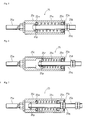
- [Fig. 5] It is a sectional side view of a neutral return mechanism.
- [Fig. 6] It is a sectional side view of the neutral return mechanism at the time of operating a forward traveling pedal.
- [Fig. 7] It is a sectional side view of the neutral return mechanism at the time of operating a rearward traveling pedal.
- [Fig. 8] It is a perspective view of a swash plate slant angle control mechanism.
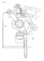
- [Fig. 9] It is a plan view of the swash plate slant angle control mechanism at the time that both the forward traveling pedal and the rearward traveling pedal are not treaded.
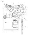
- [Fig. 10] It is a plan view of the swash plate slant angle control mechanism at the time of operating the forward traveling pedal.
- [Fig. 11] It is a plan view of the swash plate slant angle control mechanism at the time of operating the rearward traveling pedal.
-
- 1
- a vehicle frame
- 3
- an installation plate
- 4
- a HST
- 10
- a brake operating device
- 20
- a shift operating device
- 21
- a forward traveling pedal
- 22
- a rearward traveling pedal
- 73
- a shift operating rotary sleeve
- Explanation will be given on an embodiment of the present invention according to the drawings.
In addition, hereinafter, forward traveling direction of a vehicle is regarded as the front side, and rightward direction as facing the front side is regarded as the right side. The upper side in Fig. 1 is regarded as the front side, and the right side therein is regarded as the right side.
As shown in Fig. 1, astep 2 which is a footing for an operator is laid on a vehicle frame 1. Similarly, aninstallation plate 3 on which various pedals are installed is laid before thestep 2. AHST 4 is arranged below and behind thestep 2. Agearbox 5 in which planetary gear mechanism is disposed is arranged behind theHST 4. TheHST 4 and the planetary gear mechanism constitute HMT 6 (Hydro Mechanical Transmission). - A
brake operating device 10 is arranged at the left of theinstallation plate 3. Thebrake operating device 10 is provided therein with aleft brake pedal 11, aright brake pedal 12, and amaster brake pedal 13 for operating thebrake pedals
Thebrake pedals links - A
shift operating device 20 which changes speed steplessly is disposed at the right of theinstallation plate 3. Theshift operating device 20 is provided therein with aforward traveling pedal 21 and a rearward travelingpedal 22.
Theforward traveling pedal 21 and the rearward travelingpedal 22 are connected to a swash plate slantangle control mechanism 30 through alink 24. The swash plate slantangle control mechanism 30 is connected through apump control link 42 to a control arm 52 of ahydraulic pump 4P and is connected through amotor control link 41 to acontrol arm 51 of a hydraulic motor 4M. - As shown in Fig. 2, a rotary support shaft 61, whose length is substantially the same as the lateral width of the
installation plate 3, is provided laterally at the reverse side of theinstallation plate 3. The rotary support shaft 61 is hanged between astay 3v projectingly provided in the left portion of the reverse side of theinstallation plate 3 and a stay 3y provided in the right portion thereof.
The rotary support shaft 61 rotatably supports a left brakerotary sleeve 11 a to which theleft brake pedal 11 is fixed, a rightbrake rotary sleeve 12a to which theright brake pedal 12 is fixed, and a masterbrake rotary sleeve 13a to which themaster brake pedal 13 is fixed.
Thelink 15 is connected to the right end of the left brakerotary sleeve 11 a, and thelink 16 is connected to the rightbrake rotary sleeve 12a. Accordingly, each of thelinks left brake pedal 11 and theright brake pedal 12.
By operating themaster brake pedal 13, theleft brake pedal 11 and theright brake pedal 12 are operated simultaneously, and thelinks - Next, explanation will be given on the
shift operating device 20.
As shown in Figs. 2 to 4, a firstrotary support shaft 71 is provided laterally oppositely to theshift operating device 20 about theinstallation plate 3. The firstrotary support shaft 71 rotatably supports a forward traveling pedalrotary sleeve 21 a constituting the basal end of theforward traveling pedal 21 and a rearward traveling pedalrotary sleeve 22a constituting the basal end of the rearward travelingpedal 22. The firstrotary support shaft 71 is supported bystays 3v and 3w projectingly provided in the reverse side of theinstallation plate 3.
A secondrotary support shaft 72 is provided laterally below the firstrotary support shaft 71 in theinstallation plate 3. The secondrotary support shaft 72 rotatably supports a shift operatingrotary sleeve 73. The secondrotary support shaft 72 is supported bystays installation plate 3. - An
arm 21b is projectingly provided forward on the forward traveling pedalrotary sleeve 21a, anarm 73f is projectingly provided forward on the shift operatingrotary sleeve 73, and thearms link 21c. Accordingly, by treading the forward travelingpedal 21, the shift operatingrotary sleeve 73 is rotated clockwise in Fig. 4. The length of thelink 21c is adjustable so as to adjust the angle of theforward traveling pedal 21. - An
arm 22b is projectingly provided forward on the forward traveling pedalrotary sleeve 21a, anarm 73b is projectingly provided rearward on the shift operatingrotary sleeve 73, and thearm 22b and thearm 73b are connected to each other through alink 22c. Accordingly, by treading the rearward travelingpedal 22, the shift operatingrotary sleeve 73 is rotated counterclockwise in Fig. 4. The length of thelink 22c is adjustable so as to adjust the angle of the rearward travelingpedal 22. - An
arm 73m is projectingly provided downward on the shift operatingrotary sleeve 73, and the projected end of thearm 73m is connected to the tip of thelink 24. Thelink 24 is moved forward by operating theforward traveling pedal 21 and moved rearward by operating the rearward travelingpedal 22, whereby the later-discussed swash plate slantangle control mechanism 30 is interlockingly operated. - An
arm 73n is projectingly provided downward on the shift operatingrotary sleeve 73, and the projected end of thearm 73n is connected to arod 25a of aneutral return mechanism 25. Theneutral return mechanism 25 is constructed as shown in Fig. 25. The rear end of therod 25a is fixed to a front portion of acylinder 25c, and arod 25b is projected rearward from thecylinder 25c. The rear end of therod 25b is connected to astay 3a extended from theinstallation plate 3. Aspring 25s is provided in thecylinder 25c so that therod 25b is biased rearward by the biasing force of thespring 25s. - The
neutral return mechanism 25 is constructed as mentioned below.
In thecylinder 25c, thespring 25s is freely fitted onto therod 25b and interposed between a retainingring 25m, touching the inner wall surface of thecylinder 25c at the left side in the drawing, and aretaining ring 25n, freely fitted onto therod 25b. The left end of therod 25b is projected leftward from the retainingring 25m, and the projected end thereof is fixed to a retainingring 25p. Adouble nut 25q is fastened onto therod 25b so as to regulate the retainingring 25n biased rightward by thespring 25s. A retainingring 25k is fixed to the inner perimeter of the right end of thecylinder 25c. By making the left side surface of the retainingring 25k touch the retainingring 25n, the retainingring 25n is prevented from falling out. - As shown in fig. 4, the
rod 25a is connected to thearm 73n through alink connection body 25u, and therod 25b is connected to thestay 3a through alink connection body 25v. By thelink connection bodies rods link connection bodies neutral return mechanism 25 connecting thearm 73n and thestay 3 a. - With regard to the above-mentioned construction, when the
forward traveling pedal 21 is operated, therod 25a is pulled forward and the state shown in Fig. 6 is realized. When the forward travelingpedal 21 is released, therod 25a is returned to the state shown in Fig. 5.
When the rearward travelingpedal 22 is operated, therod 25a is pushed rearward and the state shown in Fig. 7 is realized. When the forward travelingpedal 21 is released, therod 25a is returned to the state shown in Fig. 5.
By adjusting the overall length of theneutral return mechanism 25, the angle of thearm 73n, that is, the angular position of the shift operatingrotary sleeve 73 is determined. Accordingly, the angles of theforward traveling pedal 21 and the rearward traveling pedal 22 (the slant angles about the floor), interlocked with the angular position of the shift operatingrotary sleeve 73, are adjusted. For example, the angles of thepedals - The construction of the
shift operating device 20 according to the present invention is mentioned above.
With regard to the above-mentioned construction, the forward travelingpedal 21 and the rearward travelingpedal 22 are rotatably supported by theinstallation plate 3; theinstallation plate 3 rotatably supports the shift operatingrotary sleeve 73 connected through onelink 21c to the basal end of the forward traveling pedal 21 (the forward traveling pedalrotary sleeve 21a) and connected through onelink 22c to the basal end of the rearward traveling pedal 22 (the rearward traveling pedalrotary sleeve 22a); theforward traveling pedal 21, the rearward travelingpedal 22, the shift operatingrotary sleeve 73 and theinstallation plate 3 are constructed as an integral unit; and the shift operatingrotary sleeve 73 is rotated forward and rearward interlockingly with the operation of theforward traveling pedal 21 and the rearward travelingpedal 22 so as to slant the swash plates of the hydraulic pump and the hydraulic motor of theHST 4.
With regard to this construction, theshift operating device 20 comprising theforward traveling pedal 21 and the rearward travelingpedal 22 is assembled as a unit, whereby the reliability of the assemble accuracy after imposing the device into the vehicle frame 1 is improved.
Furthermore, the link mechanism is simple so that the angle of the pedals can be adjusted easily. - The
forward traveling pedal 21 and the rearward travelingpedal 22 are pivotally connected to therotary support shaft 71 supported by theinstallation plate 3.
With regard to this construction, onerotary support shaft 71 acts as both the rotary support shaft of theforward traveling pedal 21 and the rotary support shaft of the rearward travelingpedal 22, whereby the number of parts is reduced so as to reduce the manufacture cost and assemble processes compared with the conventional construction providing rotary support shafts respectively. It is necessary to secure space for only one rotary support shaft, whereby the device is miniaturized. - The
neutral return mechanism 25, which returns the forward travelingpedal 21 and the rearward travelingpedal 22 to the position at which the tread amount is zero, is connected to the shift operatingrotary sleeve 73. According to this construction, the neutral position, at which the angles of theforward traveling pedal 21 and the rearward travelingpedal 22 are the same, can be adjusted easily.
The biasing force of thespring 25s acts directly on the shift operatingrotary sleeve 73 through therod 25a, whereby the neutral position is set with high accuracy. - The
master brake pedal 13 operating theleft brake pedal 11, theright brake pedal 12, or thepedals installation plate 3. The rotary support shaft 61 rotatably supporting the pedals is supported by theinstallation plate 3. Theleft brake pedal 11, theright brake pedal 12, themaster brake pedal 13 and theinstallation plate 3 are constructed as an integral unit.
With regard to this construction, thebrake operating device 10 is assembled as a unit, whereby the reliability of the assemble accuracy after imposing the device into the vehicle frame 1 is improved. - Next, explanation will be given on the swash plate slant
angle control mechanism 30.
As shown in Fig. 1, the forward travelingpedal 21 and the rearward travelingpedal 22 of theshift operating device 20 are interlockingly connected respectively to thecontrol arm 51 of the hydraulic motor 4M and the control arm 52 of thehydraulic pump 4P of the HST through the swash plate slantangle control mechanism 30.
As shown in Figs. 8 to 11, theshift operating device 20 is interlockingly connected respectively to thecontrol arms 51 and 52 of the hydraulic motor 4M and thehydraulic pump 4P of the HST through the swash plate slantangle control mechanism 30. The swash plate slantangle control mechanism 30 comprises afirst arm 32 interlockingly connected to thecontrol arm 51 of the hydraulic motor 4M and asecond arm 34 interlockingly connected to the control arm 52 of thehydraulic pump 4P. The first and second arms are rotatably supported on the same axis (arotary support shaft 35 and act in cooperation with each other. - Detailed explanation will be given below. The
rotary support shaft 35 is provided vertically on astay 39 fixed to the vehicle frame 1. Arotary plate 31, thefirst arm 32 and thesecond arm 34 are rotatably supported by therotary support shaft 35 in this order from upper to lower. The rear end of thelink 24 connected to the shift operatingrotary sleeve 73 of theshift operating device 20 is connected to therotary plate 31. Fig. 9 shows the case that the shift operation is not performed (the forward travelingpedal 21 and the rearward travelingpedal 22 are not treaded). In this state, when theforward traveling pedal 21 is treaded, therotary plate 31 is rotated clockwise in the drawing as shown in Fig. 10. When the rearward travelingpedal 22 is treaded, therotary plate 31 is rotated counterclockwise in the drawing as shown in Fig. 11. - When viewed in plan, the
first arm 32 is extended oppositely to aconnection part 24a of thelink 24 about therotary support shaft 35. Thefirst arm 32 is pinched by a notchedpart 31b of therotary plate 31 so as to be rotated integrally with therotary plate 31. Fig. 10 shows the state that theforward traveling pedal 21 is treaded and thelink 24 is moved forward so that thefirst arm 32 is rotated clockwise in the drawing. Fig. 11 shows the state that the rearward travelingpedal 22 is treaded and thelink 24 is moved rearward so that thefirst arm 32 is rotated counterclockwise in the drawing.
The tip of thefirst arm 32 is connected to the tip of themotor control link 41 so that thecontrol arm 51 of the hydraulic motor 4M is actuated interlockingly with the rotary operation of thefirst arm 32. By the actuation of thecontrol arm 51, the slant angle of the swash plate of the hydraulic motor 4M is changed.
It is designed so that thefirst arm 32 and themotor control link 41 are in parallel to each other when the pedals are not operated (the forward travelingpedal 21 and the rearward travelingpedal 22 are not treaded) (see Fig. 9). Accordingly, when either theforward traveling pedal 21 or the rearward travelingpedal 22 is treaded, themotor control link 41 is moved along the same direction and thecontrol arm 51 is operated along the same direction. - When viewed in plan, the
second arm 34 is extended at the position clockwise from thefirst arm 32, between thefirst arm 32 and thelink 24. One of ends of aspring 33 is held by a holdingpin 34a extended downward from the tip of thesecond arm 34. A holdingpin 31a is projectingly provided downward at the position of therotary plate 31 clockwise from thesecond arm 34, between thesecond arm 34 and thelink 24. The other end of thespring 33 is held by the holdingpin 31a. Accordingly, when therotary plate 31 is rotated clockwise in the drawing, tractive force is generated on thespring 33 so that thesecond arm 34 is rotated clockwise (the state shown in Fig. 10 that theforward traveling pedal 21 is treaded).
An engagepart 31b, which is engaged with the side surface of thesecond arm 34, is provided at the position of therotary plate 31 clockwise from thesecond arm 34, between thesecond arm 34 and thelink 24. Accordingly, when therotary plate 31 is rotated counterclockwise in the drawing and the engagepart 31b touches thesecond arm 34, thesecond arm 34 is rotated counterclockwise integrally with the rotary plate 31 (the state shown in Fig. 11 that the rearward travelingpedal 22 is treaded).
The tip of thesecond arm 34 is connected to the tip of thepump control link 42 so that the control arm 52 of thehydraulic pump 4P is actuated interlockingly with the rotary operation of thesecond arm 34. By the actuation of the control arm 52, the slant angle of the swash plate of thehydraulic pump 4P is changed. - With regard to this construction, the swash plate of the hydraulic motor 4M is interlocked with the actuation of the
first arm 32. Accordingly, when either theforward traveling pedal 21 or the rearward travelingpedal 22 is treaded, the swash plate is slanted along the same direction.
On the other hand, the swash plate of thehydraulic pump 4P is interlocked with the actuation of thesecond arm 34. Accordingly, the slant direction of the swash plate in the case of treading the forward travelingpedal 21 is opposite to that in the case of treading the rearward travelingpedal 22.
As mentioned above, thefirst arm 32 and thesecond arm 34 are rotatively operated interlockingly with the tread of theforward traveling pedal 21 or the rearward travelingpedal 22 so as to change the slant angles of the swash plates of the hydraulic motor 4M and thehydraulic pump 4P of theHST 4, whereby the speed is set and the traveling direction is reversed. - With regard to this construction, the three rotary members, the
rotary plate 31, thefirst arm 32 and thesecond arm 34 are supported by onerotary support shaft 35. Accordingly, compared with the case that these rotary members are supported by respective shafts, the part number is reduced and the device is constructed compactly.
Thefirst arm 32 and thesecond arm 34 are actuated interlockingly with each other by thespring 33 and the engagepart 31b, whereby the hydraulic motor 4M and thehydraulic pump 4P are steplessly shifted interlockingly with each other by operating theshift operating device 20. Accordingly, the shift operation is performed smoothly. Furthermore, the speed can be set optionally, whereby various setting of speed extends the extent of work. - An
angle regulation member 38 regulating the extent of rotary angle of thesecond arm 34 is provided in the swash plate slantangle control mechanism 30.
Since maximum slant angle of the swash plate of the hydraulic pump is set, the swash plate cannot be slanted in excess of the maximum slant angle. Accordingly, the rotary angle of thesecond arm 34 is necessary to be in the extent that makes the slant angle of the swash plate of the hydraulic pump the maximum. If thesecond arm 34 is rotated in excess of the extent, theHST 4 may be broken.
With regard to this construction, it is necessary to regulate the clockwise rotary angle of thesecond arm 34. Accordingly, theangle regulation member 38 is provided at the position clockwise from thesecond arm 34 and between thesecond arm 34 and the holdingpin 31 a when viewed in plan.
Accordingly, when theforward traveling pedal 21 is treaded and thesecond arm 34 is moved clockwise in the drawing and touches theangle regulation member 38, the rotation of thesecond arm 34 is regulated.
When thesecond arm 34 touches theangle regulation member 38, therotary plate 31 and thesecond arm 34 are isolated from each other so that only therotary plate 31 is rotated and thefirst arm 32 is rotated independently. Accordingly, only the extent of rotary angle of thesecond arm 34 is regulated without regulating the extent of rotary angle of thefirst arm 32.
By regulating the extent of rotary angle of thesecond arm 34 as mentioned above, the damage of the HST is prevented. - The present invention constructs a shift operating device comprising a forward traveling pedal and a rearward traveling pedal easily, and improves assemble accuracy and makes adjustment easy with regard to a shift operating device of a traveling vehicle widely.
Claims (6)
- A shift operating device of a traveling vehicle comprising a forward traveling pedal and a rearward traveling pedal separately, characterized in that:the forward traveling pedal and the rearward traveling pedal are rotatably supported by an installation plate fixed to a vehicle frame;the installation plate rotatably supports a shift operating interlock rotary sleeve connected through one link to a basal end of the forward traveling pedal and to a basal end of the rearward traveling pedal respectively;the forward traveling pedal, the rearward traveling pedal, the shift operating interlock rotary sleeve and the installation plate are constructed as an integral unit; andthe shift operating interlock rotary sleeve is rotated forward and rearward interlockingly with operation of the forward traveling pedal and the rearward traveling pedal so as to slant swash plates of a hydraulic pump and a hydraulic motor of a HST.
- The shift operating device of the traveling vehicle as set forth in claim 1, wherein the forward traveling pedal and the rearward traveling pedal are pivotally connected to a rotary support shaft supported by the installation plate.
- The shift operating device of the traveling vehicle as set forth in claim 1 or 2, wherein a neutral return mechanism, which returns the forward traveling pedal and the rearward traveling pedal to a position at which tread amount is zero, is connected to the shift operating interlock rotary sleeve.
- The shift operating device of the traveling vehicle as set forth in one of claims 1 to 3, wherein a brake operation device is arranged on the installation plate.
- The shift operating device of the traveling vehicle as set forth in one of claims 1 to 4, wherein
the shift operating device is interlockingly connected through a swash plate slant angle control mechanism to control arms of the hydraulic pump and the hydraulic motor of the HST,
the swash plate slant angle control mechanism comprises a first arm interlockingly connected to the control arm of the hydraulic motor and a second arm interlockingly connected to the control arm of the hydraulic pump, and
the first and second arms are rotatably supported on a same axis and actuated interlockingly with each other. - The shift operating device of the traveling vehicle as set forth in one of claims 1 to 5, wherein an angle regulation member regulating an extent of rotary angle of the second arm is provided in the swash plate slant angle control mechanism.
Applications Claiming Priority (2)
| Application Number | Priority Date | Filing Date | Title |
|---|---|---|---|
| JP2004265530A JP4464777B2 (en) | 2004-09-13 | 2004-09-13 | Shifting operation device for traveling vehicle |
| PCT/JP2004/014175 WO2006030535A1 (en) | 2004-09-13 | 2004-09-28 | Shift operating device for traveling vehicle |
Publications (2)
| Publication Number | Publication Date |
|---|---|
| EP1818205A1 true EP1818205A1 (en) | 2007-08-15 |
| EP1818205A4 EP1818205A4 (en) | 2008-04-02 |
Family
ID=36059802
Family Applications (1)
| Application Number | Title | Priority Date | Filing Date |
|---|---|---|---|
| EP04788242A Withdrawn EP1818205A4 (en) | 2004-09-13 | 2004-09-28 | Shift operating device for traveling vehicle |
Country Status (4)
| Country | Link |
|---|---|
| US (1) | US7877993B2 (en) |
| EP (1) | EP1818205A4 (en) |
| JP (1) | JP4464777B2 (en) |
| WO (1) | WO2006030535A1 (en) |
Cited By (1)
| Publication number | Priority date | Publication date | Assignee | Title |
|---|---|---|---|---|
| CN102416870A (en) * | 2011-10-31 | 2012-04-18 | 重庆建设摩托车股份有限公司 | Four-wheel all-terrain vehicle operating pedal structure |
Families Citing this family (13)
| Publication number | Priority date | Publication date | Assignee | Title |
|---|---|---|---|---|
| JP4445357B2 (en) * | 2004-09-13 | 2010-04-07 | ヤンマー株式会社 | Brake operating device for traveling vehicle |
| JP4683569B2 (en) * | 2007-01-29 | 2011-05-18 | ヤンマー株式会社 | Pedal unit |
| JP4845209B2 (en) * | 2007-01-29 | 2011-12-28 | ヤンマー株式会社 | Pedal unit |
| JP5184397B2 (en) * | 2009-02-06 | 2013-04-17 | ヤンマー株式会社 | HST gear shifting pedal assembly |
| US9182775B2 (en) * | 2009-10-13 | 2015-11-10 | David Gibson Perry | Foot-operated control assemblies and control methods for motorcycles |
| US8919813B2 (en) * | 2012-05-09 | 2014-12-30 | Schiller Grounds Care, Inc. | Tractor weight transfer mechanism |
| JP5860380B2 (en) * | 2012-10-30 | 2016-02-16 | ヤンマー株式会社 | Shift operation mechanism and work vehicle |
| US10591048B2 (en) * | 2014-07-09 | 2020-03-17 | Deere & Company | Continuously variable transmission pedal control system |
| KR102464878B1 (en) * | 2016-01-11 | 2022-11-09 | 주식회사 대동 | Driving control apparatus of agriculture vehicle |
| KR102464872B1 (en) * | 2016-01-11 | 2022-11-09 | 주식회사 대동 | Driving control apparatus of agriculture vehicle |
| KR102147690B1 (en) * | 2016-03-30 | 2020-08-25 | 엘에스엠트론 주식회사 | Apparatus for Correcting Neutral Position of Transmission Pedal for Agricultural Vehicle |
| KR102475753B1 (en) * | 2017-10-18 | 2022-12-08 | 엘에스엠트론 주식회사 | Agricultural Vehicle |
| WO2019078442A1 (en) * | 2017-10-18 | 2019-04-25 | 엘에스엠트론 주식회사 | Agricultural working vehicle |
Family Cites Families (12)
| Publication number | Priority date | Publication date | Assignee | Title |
|---|---|---|---|---|
| US3500633A (en) * | 1968-05-21 | 1970-03-17 | Gen Motors Corp | Control linkage for hydrostatic units |
| JPS5120394Y2 (en) * | 1971-03-22 | 1976-05-27 | ||
| US3691863A (en) * | 1971-04-28 | 1972-09-19 | Towmotor Corp | Control for hydrostatic transmission |
| US4759417A (en) * | 1986-08-27 | 1988-07-26 | Deere & Company | System and method for controlling the ground speed and enhancing the maneuverability of an off-road vehicle |
| JPH01314627A (en) * | 1988-06-13 | 1989-12-19 | Iseki & Co Ltd | Device for running actuation of tractor and the like |
| JPH0561558A (en) | 1991-08-30 | 1993-03-12 | Sharp Corp | Reference voltage generation circuit |
| JP2585276Y2 (en) * | 1992-01-28 | 1998-11-18 | 三菱農機株式会社 | Operating mechanism for hydrostatic transmission of passenger work vehicle |
| US5842378A (en) * | 1997-03-18 | 1998-12-01 | Deere & Company | Dual pedal mounting structure |
| US6279937B1 (en) * | 1999-07-20 | 2001-08-28 | Deere & Company | Intermediate shaft plate for transmission control linkage |
| JP4779196B2 (en) * | 2000-10-06 | 2011-09-28 | 井関農機株式会社 | Work vehicle |
| JP2004024070A (en) * | 2002-06-24 | 2004-01-29 | Iseki & Co Ltd | Powered vehicle |
| US6886677B2 (en) * | 2002-10-18 | 2005-05-03 | Deere & Co. | Interlock of parking brake and drive control pedals for utility vehicle |
-
2004
- 2004-09-13 JP JP2004265530A patent/JP4464777B2/en not_active Expired - Fee Related
- 2004-09-28 US US11/575,200 patent/US7877993B2/en not_active Expired - Fee Related
- 2004-09-28 EP EP04788242A patent/EP1818205A4/en not_active Withdrawn
- 2004-09-28 WO PCT/JP2004/014175 patent/WO2006030535A1/en not_active Ceased
Non-Patent Citations (2)
| Title |
|---|
| No further relevant documents disclosed * |
| See also references of WO2006030535A1 * |
Cited By (2)
| Publication number | Priority date | Publication date | Assignee | Title |
|---|---|---|---|---|
| CN102416870A (en) * | 2011-10-31 | 2012-04-18 | 重庆建设摩托车股份有限公司 | Four-wheel all-terrain vehicle operating pedal structure |
| CN102416870B (en) * | 2011-10-31 | 2013-11-06 | 重庆建设摩托车股份有限公司 | Control pedal structure of four-wheel all-terrain vehicle |
Also Published As
| Publication number | Publication date |
|---|---|
| WO2006030535A1 (en) | 2006-03-23 |
| US7877993B2 (en) | 2011-02-01 |
| EP1818205A4 (en) | 2008-04-02 |
| JP2006076525A (en) | 2006-03-23 |
| US20080028882A1 (en) | 2008-02-07 |
| JP4464777B2 (en) | 2010-05-19 |
Similar Documents
| Publication | Publication Date | Title |
|---|---|---|
| US7877993B2 (en) | Shift operating device for traveling vehicle | |
| EP3421283A1 (en) | Working vehicle | |
| EP1923608B1 (en) | Working vehicle | |
| CN104110492A (en) | Riding-type rice transplanter | |
| JP4882564B2 (en) | Working machine lifting operation device | |
| JP2008017803A5 (en) | ||
| JP2005119466A (en) | Travel transmission for work vehicle | |
| KR102282516B1 (en) | Driving control apparatus of agriculture vehicle | |
| JP4423062B2 (en) | Tractor shifting operation structure | |
| JP4795835B2 (en) | Hydraulic drive vehicle | |
| KR102464872B1 (en) | Driving control apparatus of agriculture vehicle | |
| JP4408781B2 (en) | Shifting structure of work equipment | |
| JP2005233260A5 (en) | ||
| JP3143372B2 (en) | Work vehicle operation control structure | |
| KR102464878B1 (en) | Driving control apparatus of agriculture vehicle | |
| JP4594754B2 (en) | Shifting structure of work equipment | |
| JP4779196B2 (en) | Work vehicle | |
| JP4634972B2 (en) | Work vehicle travel control device | |
| EP3613622B1 (en) | Automatic throttle | |
| JP2011152823A (en) | Working vehicle | |
| JP2003265008A (en) | Transmission structure of rice transplanter | |
| JP4826285B2 (en) | Speed change operation device for work vehicle | |
| KR100837893B1 (en) | Transmission of Working Vehicle | |
| KR20170107696A (en) | Linkage Apparatus for Agricultural Vehicle | |
| JP2003219714A (en) | Operation lever positioning mechanism |
Legal Events
| Date | Code | Title | Description |
|---|---|---|---|
| PUAI | Public reference made under article 153(3) epc to a published international application that has entered the european phase |
Free format text: ORIGINAL CODE: 0009012 |
|
| 17P | Request for examination filed |
Effective date: 20070413 |
|
| AK | Designated contracting states |
Kind code of ref document: A1 Designated state(s): DE FR GB IT |
|
| DAX | Request for extension of the european patent (deleted) | ||
| RBV | Designated contracting states (corrected) |
Designated state(s): DE |
|
| A4 | Supplementary search report drawn up and despatched |
Effective date: 20080305 |
|
| 17Q | First examination report despatched |
Effective date: 20080728 |
|
| GRAP | Despatch of communication of intention to grant a patent |
Free format text: ORIGINAL CODE: EPIDOSNIGR1 |
|
| GRAJ | Information related to disapproval of communication of intention to grant by the applicant or resumption of examination proceedings by the epo deleted |
Free format text: ORIGINAL CODE: EPIDOSDIGR1 |
|
| RBV | Designated contracting states (corrected) |
Designated state(s): DE FR GB IT |
|
| GRAP | Despatch of communication of intention to grant a patent |
Free format text: ORIGINAL CODE: EPIDOSNIGR1 |
|
| RIC1 | Information provided on ipc code assigned before grant |
Ipc: G05G 1/00 20060101ALI20090323BHEP Ipc: B60K 20/02 20060101AFI20090323BHEP Ipc: F16H 61/40 20060101ALI20090323BHEP Ipc: B60K 17/10 20060101ALI20090323BHEP Ipc: B60K 20/04 20060101ALI20090323BHEP |
|
| STAA | Information on the status of an ep patent application or granted ep patent |
Free format text: STATUS: THE APPLICATION IS DEEMED TO BE WITHDRAWN |
|
| 18D | Application deemed to be withdrawn |
Effective date: 20090916 |